

Page 1
INSTALLATION MANUAL
INVERTER WALL MOUNTED
SPLIT TYPE AIR CONDITIONER
(L Series)
IM-5WMYJ-1110(0)-McQuay
Part Number: R08019035856
© 2010 McQuay International
Page 2

Page 3
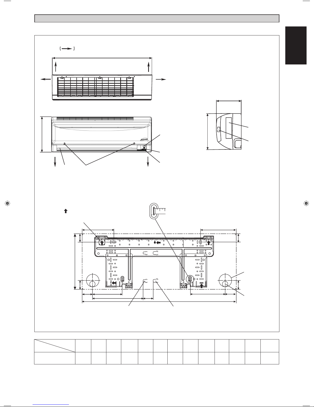
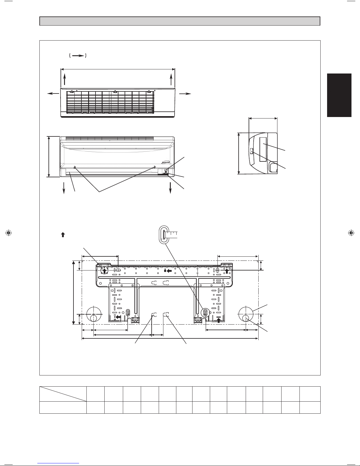
OUTLINE AND DIMENSIONS
Indoor Unit [M5WMYL Series]
THE MARK SHOWS PIPING DIRECTION
A
LEFT RIGHT
B
REAR REAR
TOP VIEW
BOTTOMBOTTOM
LOUVER FRONT GRILLE FIXED
SCREWS (INSIDE)
FRONT VIEW
SIGNAL RECEIVER
INDOOR UNIT
ON/OFF SWITCH
ROOM TEMPERATURE
THERMIRTOR (INSIDE)
B
C
SIDE VIEW
NAME PLATE
TERMINAL
BLOCK
WITH EARTH
TERMINAL
h
s
i
l
g
nE
English
Original Instruction
Model
Dimension
Use tape measure
Recommended mounting
plate retention spots
(5 spots in all)
D
F
B
G
H
J
L
Liquid pipe end Gas pipe end
M
INSTALLATION PLATE All dimensions are in mm
as shown.
Position the end
of a tape measure
at
X
A
E
F
Through the wall
hole Ø 65mm
G
K
I
Drain hose
position
A B C D E F G H I J K L M
M5WMY10/15LR
800 288 206 166 184 42 46 55 56 154 182 263 52
1-1
Page 4
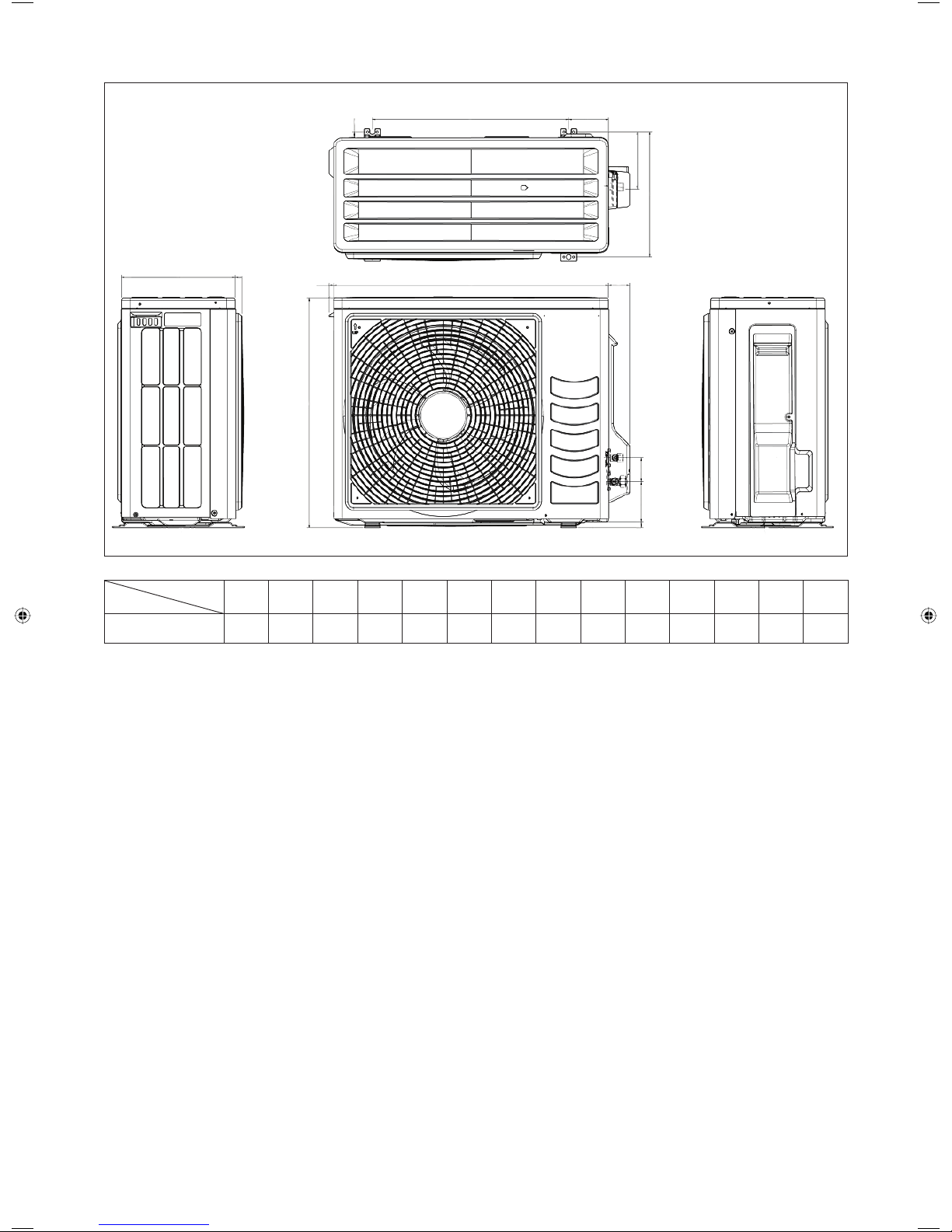
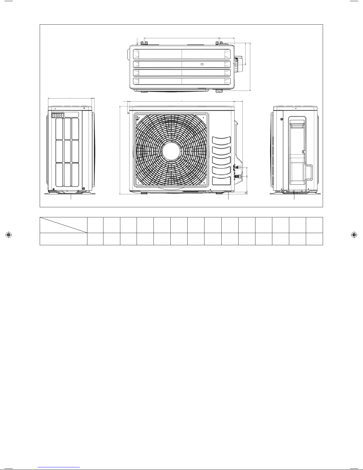
Outdoor Unit [M5LCY10/15FR]
G
E
F
D
A
BC
IH
All dimensions are in mm
N
J
LK
Dimension
Model
ABCDEFGH I JKLMN
M5LCY10/15FR 550 658 51 11 273 16 14 470 96 299 94 60 14 133
1-2
Page 5
INSTALLATION MANUAL
This manual provides the procedures of installation to ensure a safe and good standard of operation for the air
conditioner unit.
Special adjustment may be necessary to suit local requirements.
Before using your air conditioner, please read this instruction manual carefully and keep it for future reference.
This appliance is intended to be used by expert or trained users in shops, in light industry and on farms, or for
commercial use by lay persons.
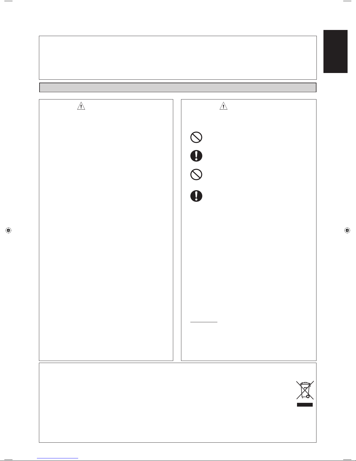
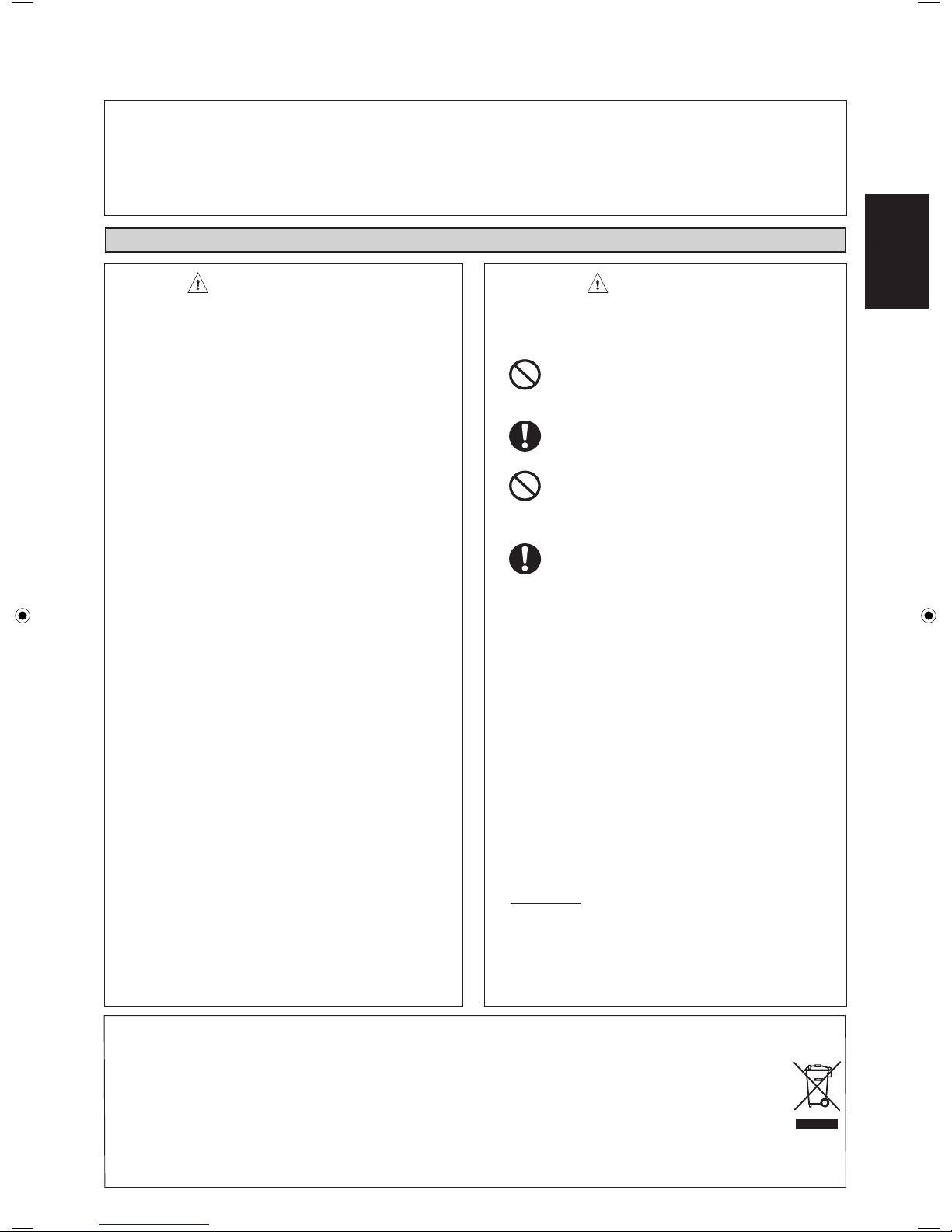
SAFETY PRECAUTIONS
WARNING
• Installation and maintenance should be performed by
qualifi ed persons who are familiar with local code and
regulation, and experienced with this type of appliance.
• All fi eld wiring must be installed in accordance with the
national wiring regulation.
• Ensure that the rated voltage of the unit corresponds to
that of the name plate before commencing wiring work
according to the wiring diagram.
• The unit must be GROUNDED to prevent possible hazard
due to insulation failure.
• All electrical wiring must not touch the refrigerant piping
or any moving parts of the fan motors.
• Confi rm that the unit has been switched OFF before
installing or servicing the unit.
• Disconnect from the main power supply before servicing
the air conditioner unit.
• DO NOT pull out the power cord when the power is ON.
This may cause serious electrical shocks which may
result in fi re hazards.
• Keep the indoor and outdoor units, power cable and
transmission wiring, at least 1m from TVs and radios, to
prevent distorted pictures and static. {Depending on the
type and source of the electrical waves, static may be
heard even when more than 1m away}.
Please take note of the following important points
when installing.
• Do not install the unit where leakage of fl ammable
gas may occur.
If gas leaks and accumulates around the unit, it
may cause fi re ignition.
• Ensure that drainage piping is connected properly.
If the drainage piping is not connected properly, it
may cause water leakage which will dampen the
furniture.
• Do not overcharge the unit.
This unit is factory pre-charged. Overcharge will
cause over-current or damage to the compressor.
• Ensure that the unit’s panel is closed after service or
installation.
Unsecured panels will cause the unit to operate
noisily.
• Sharp edges and coil surfaces are potential locations
which may cause injury hazards. Avoid from being in
contact with these places.
• Before turning off the power supply, set the remote
controller’s ON/OFF switch to the “OFF” position to
prevent the nuisance tripping of the unit. If this is not
done, the unit’s fans will start turning automatically when
power resumes, posing a hazard to service personnel or
the user.
• Do not install the units at or near doorway.
• Do not operate any heating apparatus too close to the
air conditioner unit or use in room where mineral oil, oil
vapour or oil steam exist, this may cause plastic part to
melt or deform as a result of excessive heat or chemical
reaction.
• When the unit is used in kitchen, keep fl our away from
going into suction of the unit.
• This unit is not suitable for factory used where cutting oil
mist or iron powder exist or voltage fl uctuates greatly.
• Do not install the units at area like hot spring or oil
refi nery plant where sulphide gas exists.
• Ensure the color of wires of the outdoor unit and the
terminal markings are same to the indoors respectively.
• IMPORTANT : DO NOT INSTALL OR USE THE AIR
CONDITIONER UNIT IN A LAUNDRY ROOM.
• Do not use joined and twisted wires for incoming power
supply.
• For any enquiries on spare part, please contact your
authorized dealer.
• The equipment is not intended for use in a potentially
explosive atmosphere.
CAUTION
h
s
i
l
g
nE
English
Disposal requirements
Your air conditioning product is marked with this symbol. This means that electrical and electronic products shall not
be mixed with unsorted household waste.
Do not try to dismantle the system yourself: the dismantling of the air conditioning system, treatment of the refrigerant,
of oil and of other parts must be done by a qualifi ed installer in accordance with relevant local and national legislation.
Air conditioners must be treated at a specialized treatment facility for re-use, recycling and recovery. By ensuring this
product is disposed of correctly, you will help to prevent potential negative consequences for the environment and
human health. Please contact the installer or local authority for more information.
Batteries must be removed from the remote controller and disposed of separately in accordance with relevant local
and national legislation.
NOTICE
1-3
Page 6
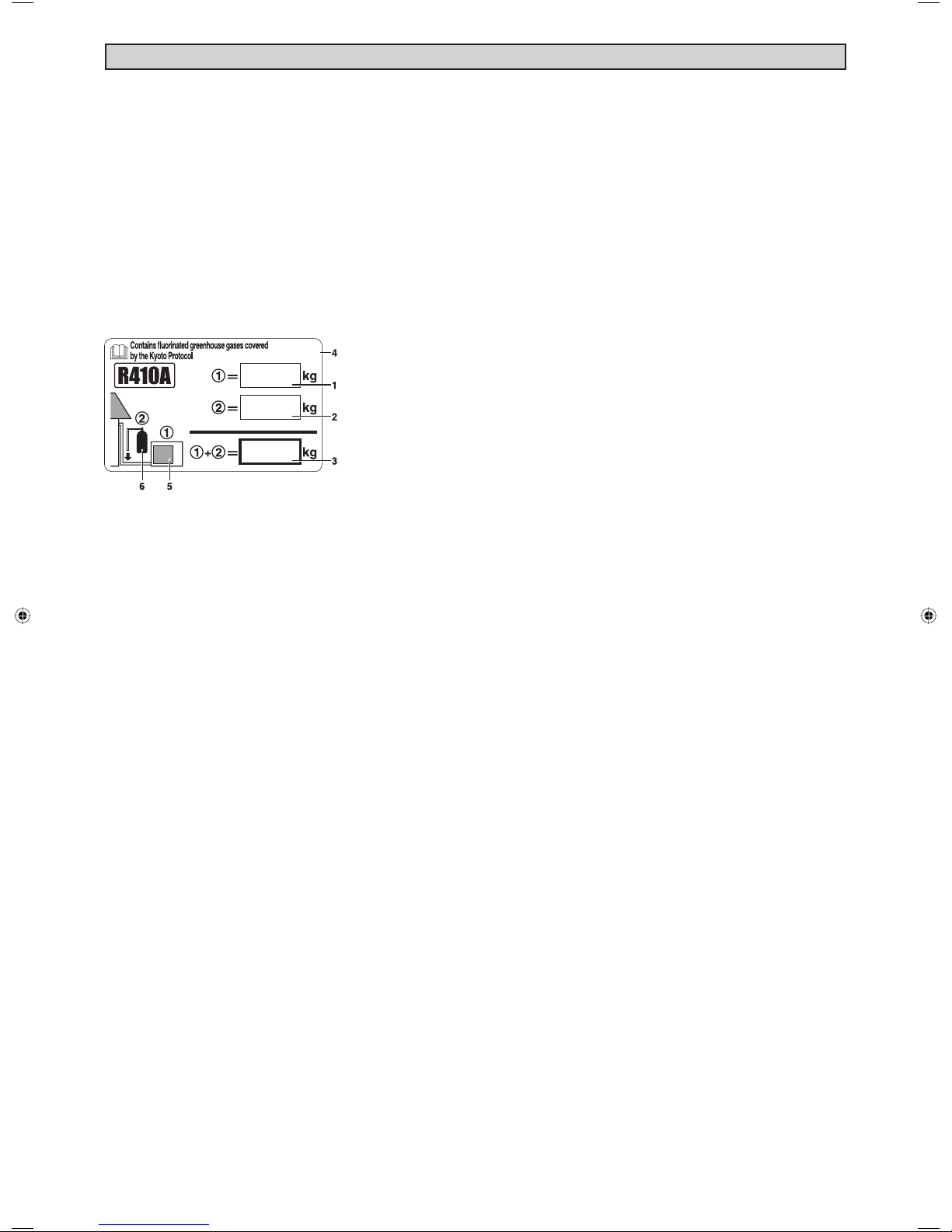
IMPORTANT
Important information regarding the refrigerant used
This product contains fl uorinated greenhouse gases covered by the Kyoto Protocol.
Do not vent gases into the atmosphere.
Refrigerant type: R410A
(1)
GWP
value: 1975
(1)
GWP = global warming potential
Please fi ll in with indelible ink,
■ A the factory refrigerant charge of the product,
■ B the additional refrigerant amount charged in the fi eld and
■ A + B the total refrigerant charge
on the refrigerant charge label supplied with the product.
The fi lled out label must be adhered in the proximity of the product charging port (e.g. onto the inside of the service
cover).
1 factory refrigerant charge of the product:
see unit name plate
(2)
2 additional refrigerant amount charged in the fi eld
3 total refrigerant charge
4 contains fl uorinated greenhouse gases covered by the Kyoto Protocol
5 outdoor unit
6 refrigerant cylinder and manifold for charging
(2)
In case of multiple indoor systems, only 1 label must be adhered*, mentioning the total factory refrigerant charge of
all indoor units connected in the refrigerant system.
Periodical inspections for refrigerant leaks may be required depending on European or local legislation. Please
contact your local dealer for more information.
* on the outdoor unit
1-4
Page 7
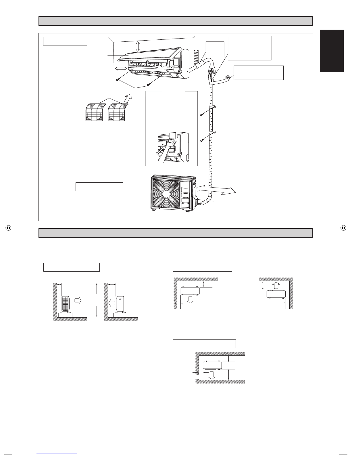
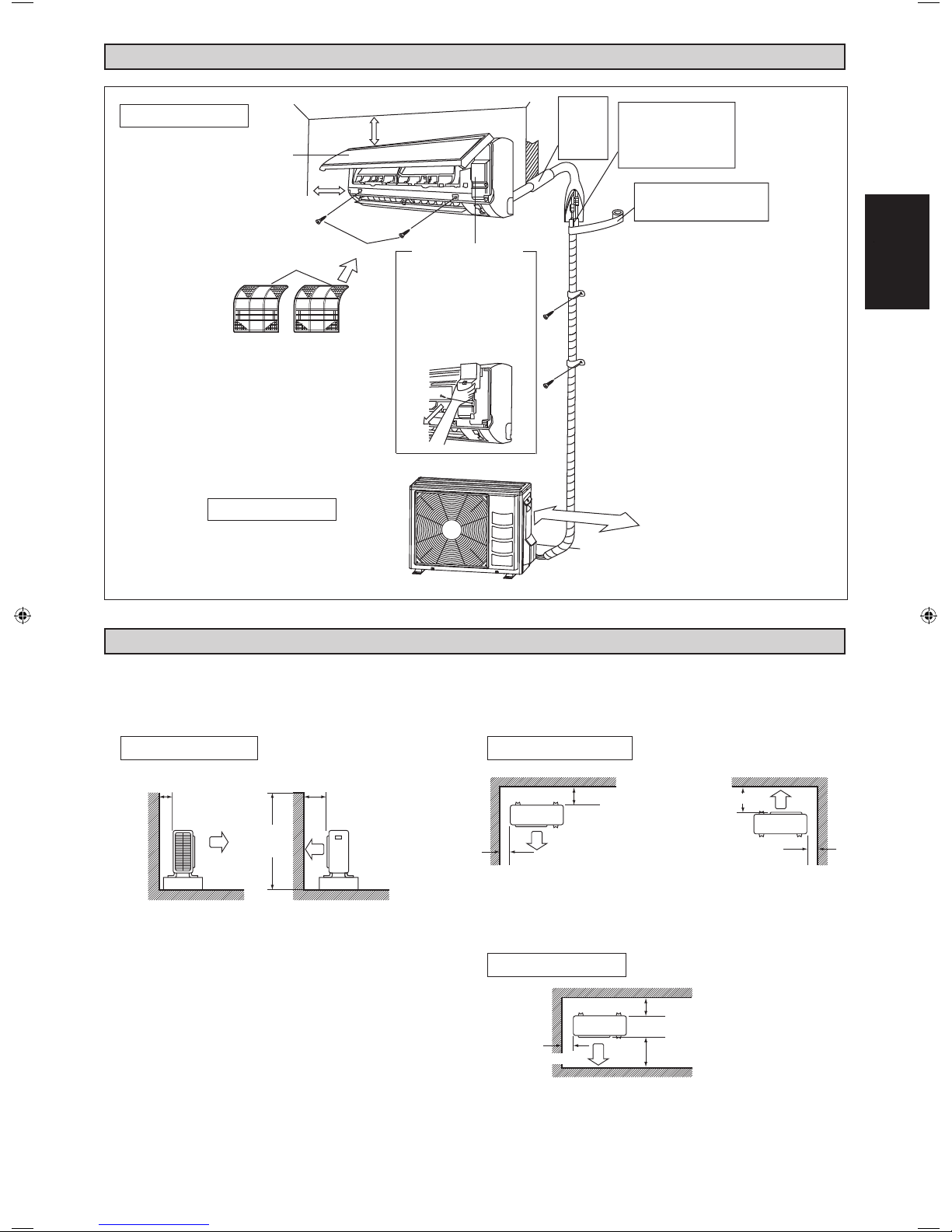
INSTALLATION DIAGRAM
Indoor Unit
Front Panel
50mm or more from walls
(on both sides)
Air fi lter
Outdoor Unit
M4 X 12L
30mm or more from ceiling
Service lid
• Opening service lid
Service lid is opening/closing
type.
• Opening method
1) Remove the service lid
screws.
2) Pull out the service lid
diagonally down in the direction
of the arrow.
3) Pull down.
Caulk pipe
hole gap
with putty.
250mm from wall
Cut thermal insulation pipe to
an appropriate length and wrap
it with tape, making sure that no
gap is left in the insulation pipe’s
cut line.
.
Wrap the insulation pipe with the
fi nishing tape from bottom to top.
h
s
i
l
g
nE
English
INSTALLATION OF THE OUTDOOR UNIT
• Where a wall or other obstacle is in the path of outdoor unit’s intake or exhaust airflow, follow the installation guidelines below.
• For any of the below installation patterns, the wall height on the exhaust side should be 1200mm or less.
Wall facing one side Walls facing two sides
More than 50 More than 100
1200
or less
Side view
More than
100
n 50ahteroM n 50ahteroM
Top view
More than 150
Walls facing three sides
More than 150
More than 50
More than 300
Top view
unit: mm
1-5
Page 8
Drain work. (Heat Pump Unit Only)
1) Use drain plug for drainage.
2) If the drain port is covered by a mounting base or fl oor surface, place
additional foot bases of at least 30mm in height under the outdoor unit’s
feet.
3) In cold areas, do not use a drain hose with the outdoor unit.
(Otherwise, drain water may freeze, impairing heating performance.)
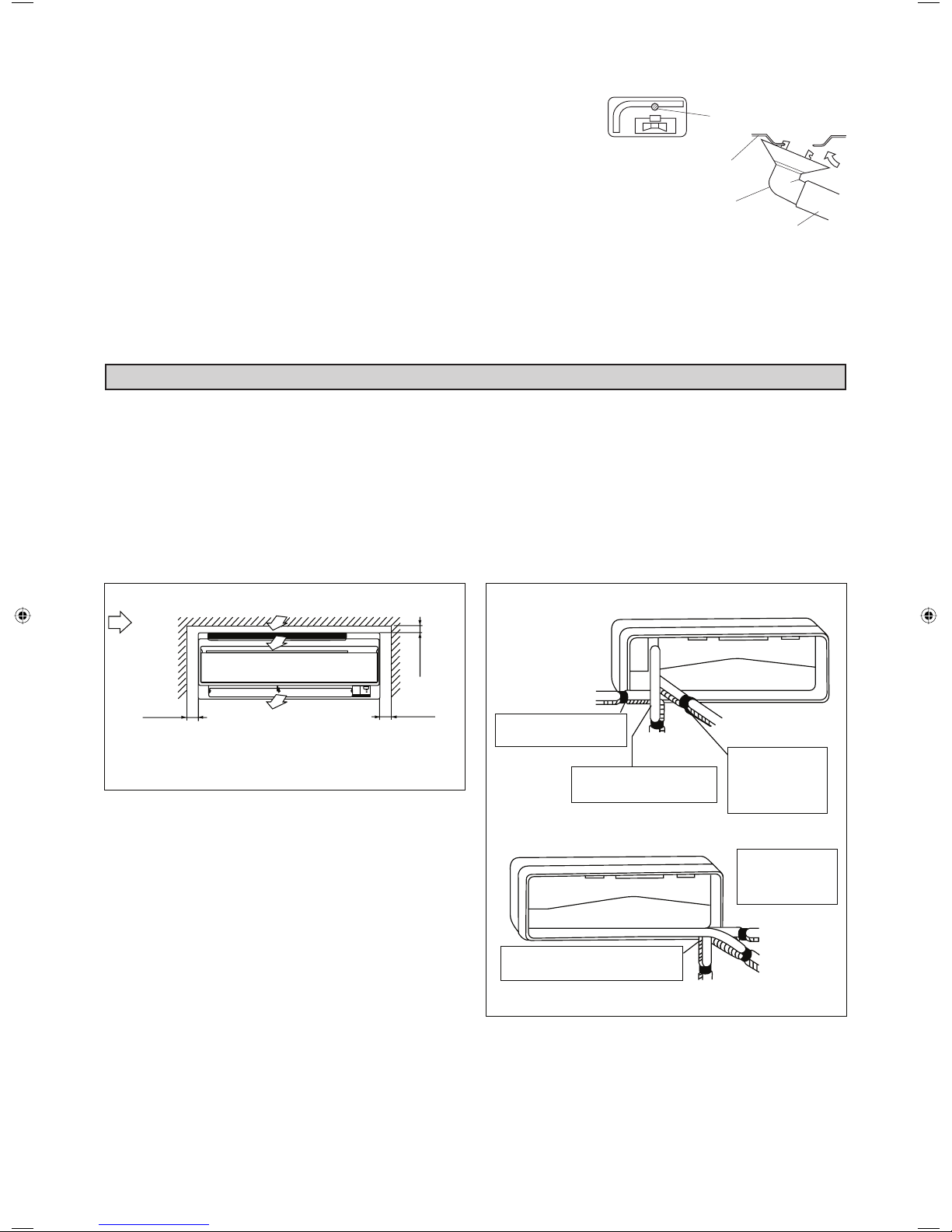
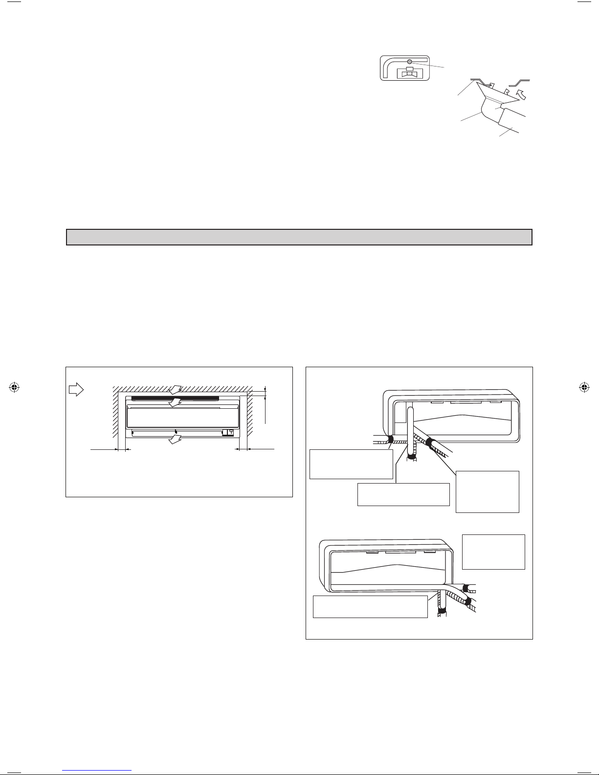
INSTALLATION OF THE INDOOR UNIT
Drain water hole
Bottom frame
Drain plug
Hose (available commercially,
inner dia. 16mm)
The indoor unit must be installed in such a way so as to
prevent short circuit of the cool discharged air with the hot
return air. Please follow the installation clearance shown
in the fi gure. Do not place the indoor unit where there
could be direct sunlight shining on it. Also, this location
must be suitable for piping and drainage, and be away
from doors or windows.
Air fl ow
(Indoor)
(Space for
performance)
min. 30
min. 50 min. 50
(Space for
maintenance)
Required space
(Space for
maintenance)
All dimensions are in mm
The refrigerant piping can be routed to the unit in a
number of ways (left or right from the back of the unit), by
using the cut-out holes on the casing of the unit.
Bend the pipes carefully to the required position in order
to align it with the holes. For the side and bottom out,
hold the bottom of the piping and then position it to the
required direction. The condensation drain hose can be
taped to the pipes.
Right-side, right-back or right-bottom piping
Right-side
piping
Remove pipe port cover
here for right-side piping
here for right-bottom piping
Right-bottom
piping
Remove pipe port cover
Right-back piping
Bind coolant pipe and
drain hose together
with insulating tape.
Left-side, left-back or left-bottom piping
Remove pipe port cover here for left-bottom
piping
1-6
Left-bottom piping
Remove pipe port cover
here for left-side piping
Left-side piping
Left-back piping
Page 9
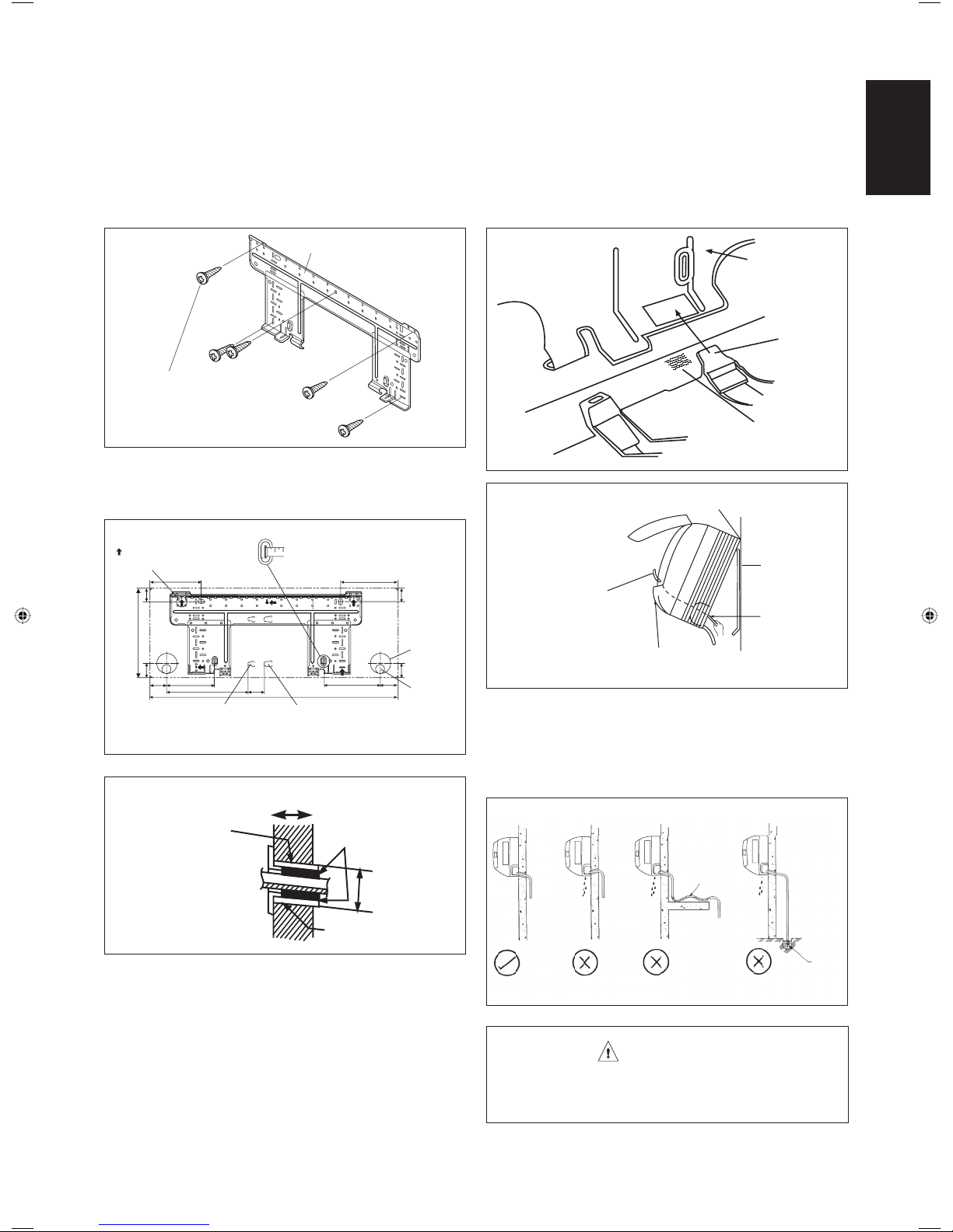
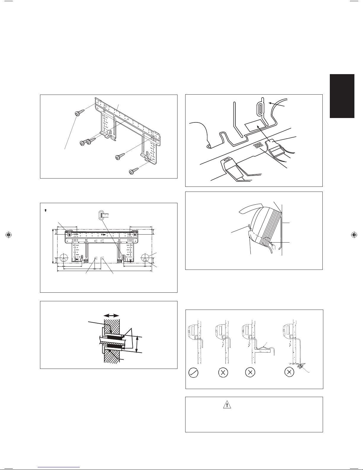
Mounting Installation Plate
Ensure that the wall is strong enough to withstand the
weight of the unit. Otherwise, it is necessary to reinforce
the wall with plates, beams or pillars.
Use the level gauge for horizontal mounting, and fi x it
with 5 suitable screws.
In case the rear piping draws out, drill a hole 65mm in
diameter with a cone drill, slightly lower on the outside
wall (see fi gure).
How To Attach The Indoor Unit
Hook the claws of the bottom frame to the mounting
plate.
How To Remove The Indoor Unit
Push up the marked area (at the lower part of the front
grille) to release the claws.
h
s
i
l
g
nE
English
Mounting plate
Mounting plate
fi xing screw
Recommended Mounting Plate Retention Spots And
Dimensions
Use tape measure as shown.
Recommended mounting plate
retention spots (5 spots in all)
166
2
.2
4
882
9
.5
4
153.8
Hole with cone drill
Wall embedded pipe
(Field supply)
263
Position the end of a tape
measure at
51.9
800
Gas pipe endLiquid pipe end
X
184
181.7
2.24
Through
the wall
hole
Ø 65mm
9.54
55.554.5
Drain
hose
position
All dimensions are in mm
OutsideInside
Caulking
Mounting plate
Clip
Front grille
When stripping the ends
of interconnecting wires in
advance, bind right ends
of wires with insulating
tape.
Bottom frame
Hand indoor unit’s hook here.
Wire guide
Mark (Rear side)
Mounting plate
Interconnecting
wires
Water Drainage Piping
The indoor drain pipe must be in a downward gradient for
smooth drainage. Avoid situations that are likely to cause
water to leak.
Water Drainage
Wall hole cover
(Field supply)
Mount The Unit Onto The Installation Plate
Hook the indoor unit onto the upper portion of the
installation plate (Engage the two hooks at the rear top
of the indoor unit with the upper edge of the installation
plate). Ensure that the hooks are properly seated on the
installation plate by moving it to the left and right.
Ø 65
Wall embedded pipe
(Field supply)
Water
Retention
Water
Leaking
Correct Wrong Wrong Wrong
Water
Leaking
Water
Leaking
CAUTION
• Do not install the unit at altitude over 2000m for both
indoor & outdoor.
1-7
End
dipped
into
water
Drain
Page 10

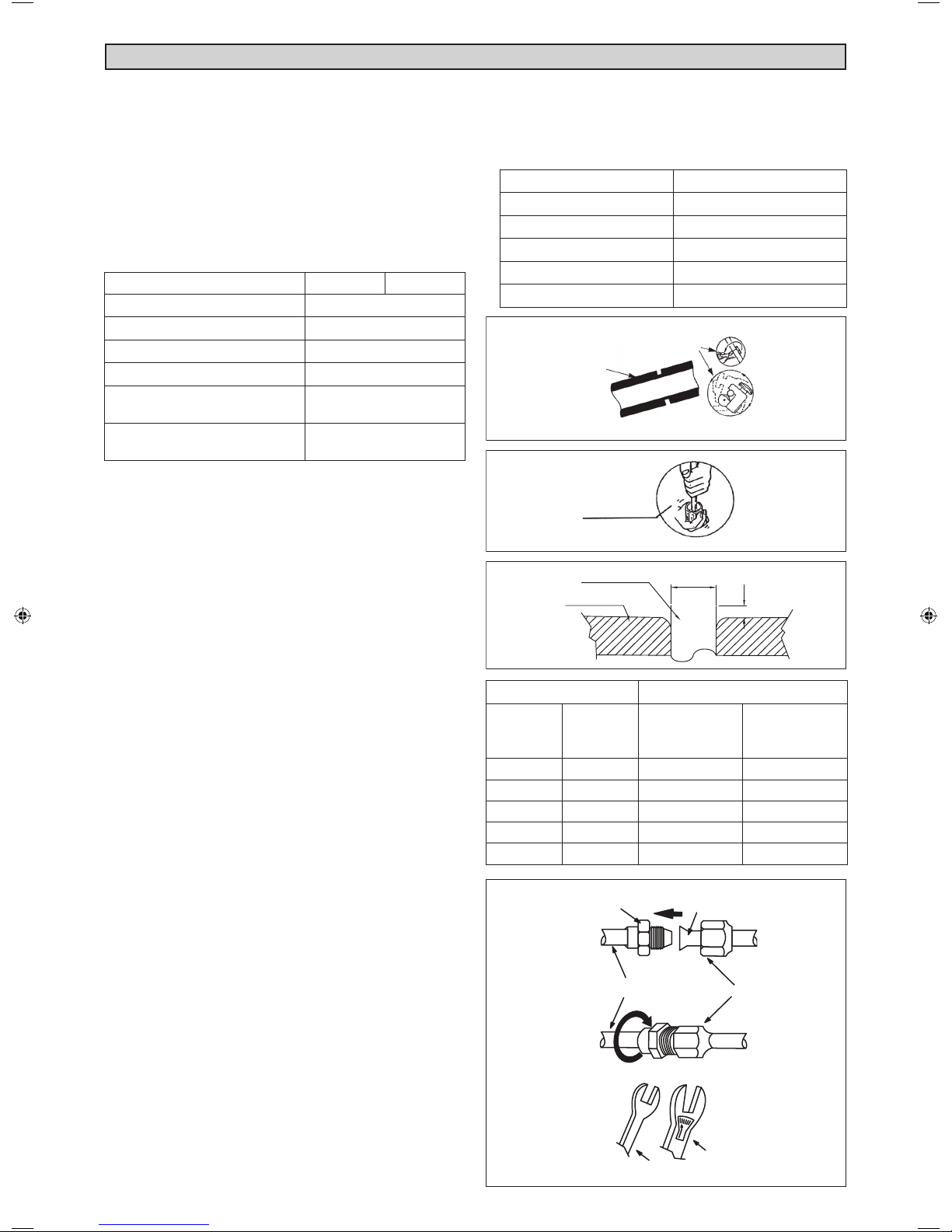
REFRIGERANT PIPING
Allowable Piping Length
If the pipe is too long, both the capacity and reliability of
the unit will drop. As the number of bends increases,
resistance to the fl ow of refrigerant system increases, thus
lowering cooling capacity. As a result, the compressor
may become defective. Always choose the shortest path
and follow the recommendations as tabulated below:
Model
Min. Allowable Length, m
Max. Allowable Length, m
Additional charge of refrigerant
Max. Allowable Elevation, m
Gas Pipe Size, mm/(in)
Liquid Pipe Size
, mm/(in)
10 15
3
15
20
10
9.52 (3/8")
6.35 (1/4")
*Be sure to add the proper amount of additional refrigerant.
Failure to do so may result in reduced performance.
Remark: The refrigerant pre-charged in the outdoor
unit is for piping length up to 7.5m.
Piping Works and Flaring technique
• Do not use contaminated or damaged copper tubing. If
any piping, evaporator or condenser had been exposed
or had been opened for 15 seconds or more, the system
must be vacuumed. Generally do not remove plastic,
rubber plugs and brass nuts from the valves, fi ttings,
tubing and coils until it is ready to connect suction or
liquid line into valves or fi ttings.
• If any brazing work is required, ensure that nitrogen
gas is passed through coil and joints while the brazing
work is being done. This will eliminate soot formation
on the inside wall of copper tubings.
• Cut the pipe stages by stages, advancing the blade of
pipe cutter slowly. Extra force and a deep cut will cause
more distortion of pipe and therefore extra burr. See
Figure A.
• Remove burrs from cut edges of the pipes with remover.
See Figure B. Hold the pipe on top position and burr
removel at lower position to prevent metal chips from
entering the pipe. This will avoid unevenness on the
fl are faces which will cause gas leak.
• Insert the fl are nuts, mounted on the connection parts
of both the indoor unit and outdoor unit, into the copper
pipes.
• The exact length of pipe protruding from the top surface
of the swaging block is determined by the fl aring tool.
See Figure C.
• Fix the pipe fi rmly on the swaging block. Match the
centers of both the swaging block and the fl aring punch,
then tighten the fl aring punch fully.
• The refrigerant pipe connection are insulated by closed
cell polyurethane.
• When tightening the fl are nut with the torque wrench,
ensure that the tightening direction follows the arrow
indicated on the wrench.
• The refrigerant pipe connection are insulated by closed
cell polyurethane.
Pipe Size, mm (in) Torque, Nm / (ft-Ib)
6.35 (1/4") 18 (13.3)
9.52 (3/8") 42 (31.0)
12.70 (1/2") 55 (40.6)
15.88 (5/8") 65 (48.0)
19.05 (3/4") 78 (57.6)
Figure A
Cutting Copper Tube
1/4t
Figure B
Remove Burr
Figure C
Copper Tube
Swaging Block
D
A
Ø Tube, D A (mm)
Inch mm Imperial
(Wing-nut Type)
Rigid
(Clutch Type)
1/4" 6.35 1.3 0.7
3/8" 9.52 1.6 1.0
1/2" 12.70 1.9 1.3
5/8" 15.88 2.2 1.7
3/4" 19.05 2.5 2.0
Figure D
Flare Joint
Indoor Piping
Flared Tube
Flare Nut
Piping Connection To The Units
• Align the center of the piping and tighten the fl are nut
suffi ciently with fi ngers. See Figure D.
• Finally, tighten the fl are nut with torque wrench until the
wrench clicks.
1-8
Spanar
Torque Wrench
Page 11
ELECTRICAL WIRING CONNECTION
IMPORTANT :* The fi gures shown in the table are for information purpose only. They should be checked and
selected to comply with the local/national codes of regulations. This is also subject to the type of
installation and conductors used.
** The appropriate voltage range should be checked with label data on the unit.
Indoor Unit
Terminal Block
1
2
SIG
N
L
Outdoor Unit
Terminal Block
1
2
SIG
Power Supply
Cable
There mustbe an all poledisconnection
in the supply mains with a contact
seperation of at least 3mm.
Model 10
Voltage range**
Power supply cable size* mm²
Number of core
Interconnection cable size* mm²
Number of core
Recommended time delay fuse A
220V - 240V / 1Ph / 50Hz+
1.5
3
1.5
4
15
* If the length of the cable is more than 2m, use cable
with bigger size.
15
1.5
3
1.5
4
15
h
s
i
l
g
nE
English
• All wires must be fi rmly connected.
• Make sure all the wire do not touch the refrigerant pipings, compressor or any moving parts.
• The connecting wire between the indoor unit and the outdoor unit must be clamped by using provided cord
anchorage.
• The power supply cord must be equivalent to H07RN-F which is the minimum requirement.
• Make sure no external pressure is applied to the terminal connectors and wires.
• Make sure all the covers are properly fi xed to avoid any gap.
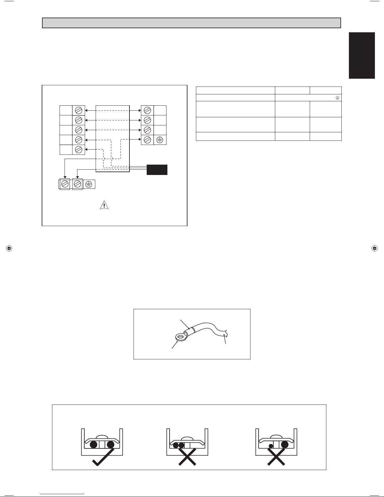
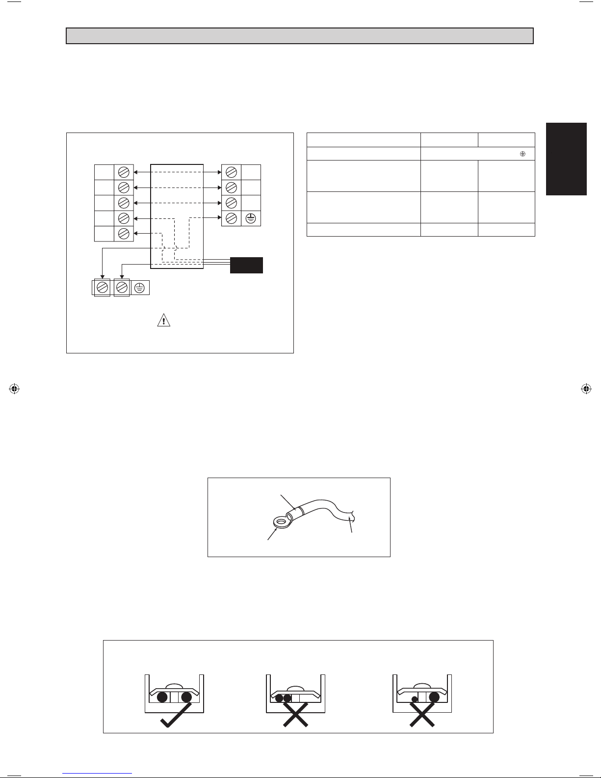
• Use round crimp-style terminal for connecting wires to the power supply terminal block. Connect the wires by
matching to the indication on terminal block. (Refer to the wiring diagram attached on the unit.)
Attach insulation sleeve
Round crimp-style terminal
Electric wire
• Used the correct screwdriver for terminal screws tightening. Unsuitable screwdrivers can damage the screw head.
• Over tightening can damage the terminal screws.
• Do not connect wire of different gauge to same terminal.
• Keep wiring in an orderly manner. Prevent the wiring from obstructing other parts and the terminal box cover.
Connect wires of the
same gauge to both side.
Do not connect wires of the
same gauge to one side.
Do not connect wires
of different gauges.
1-9
Page 12

SPECIAL PRECAUTIONS WHEN DEALING WITH R410A UNIT
R410A is a new HFC refrigerant which does not damage
the ozone layer. The working pressure of this new
refrigerant is 1.6 times higher than conventional refrigerant (R22), thus proper installation / servicing is essential.
• Never use refrigerant other than R410A in an air
conditioner which is designed to operate with R410A.
• POE or PVE oil is used as lubricant for R410A
compressor, which is different from the mineral oil used
for R22 compressor. During installation or servicing,
extra precaution must be taken not to expose the
R410A system too long to moist air. Residual POE or
PVE oil in the piping and components can absorb
moisture from the air.
• To prevent mischarging, the diameter of the service
port on the flare valve is different from that of R22.
Vacuuming is necessary to eliminate all moisture and air from the system.
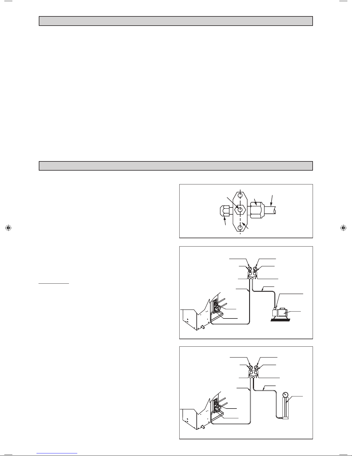
Vacuuming The Piping And The Indoor Unit
Except for the outdoor unit which is pre-charged with
refrigerant, the indoor unit and the refrigerant connection
pipes must be air-purged because the air containing
moisture that remains in the refrigerant cycle may cause
malfunction of the compressor.
• Remove the caps from the valve and the service port.
• Connect the center of the charging gauge to the
vacuum pump.
• Connect the charging gauge to the service port of the
3-way valve.
• Start the vacuum pump. Evacuate for approximately 30
minutes. The evacuation time varies with different
vacuum pump capacity. Confirm that the charging
gauge needle has moved towards -760mmHg.
Caution
• If the gauge needle does not move to -760mmHg, be
sure to check for gas leaks (using the refrigerant
detector) at flare type connection of the indoor and
outdoor unit and repair the leak before proceeding to
the next step.
• Close the valve of the changing gauge and stop the
vacuum pump.
• On the outdoor unit, open the suction valve (3 way)
and liquid valve (2 way) (in anti-clockwise direction)
with 4mm key for hexagon sacked screw.
Charge Operation
This operation must be done by using a gas cylinder and
a precise weighing machine. The additional charge is
topped-up into the outdoor unit using the suction valve via
the service port.
• Remove the service port cap.
• Connect the low pressure side of the charging gauge to
the suction service port center of the cylinder tank and
close the high pressure side of the gauge. Purge the air
from the service hose.
• Start the air conditioner unit.
• Open the gas cylinder and low pressure charging valve.
• When the required refrigerant quantity is pumped into
the unit, close the low pressure side and the gas
cylinder valve.
• Disconnect the service hose from service port. Put back
the service port cap.
• Use tools and materials exclusively for refrigerant
R410A. Tools exclusively for R410A are manifold valve,
charging hose, pressure gauge, gas leak detector, flare
tools, torque wrench, vacuum pump and refrigerant
cylinder.
• As an R410A air conditioner incurs higher pressure
than R22 units, it is essential to choose the copper
pipes correctly. Never use copper pipes thinner than
0.8mm even though they are available in the market.
• If the refrigerant gas leakage occurs during installation /
servicing, be sure to ventilate fully. If the refrigerant gas
comes into contact with fire, a poisonous gas may
occur.
• When installing or removing an air conditioner, do not
allow air or moisture to remain in the refrigerant cycle.
VACUUMING AND CHARGING
Allen key
Service Port
LOW PRESSURE GAUGE
LOW PRESSURE GAUGE
1-10
-760mmHg
HANDLE LO
CHARGE HOSE
LIQUID VALVE
GAS VALVE
(3-WAY)
-760mmHg
HANDLE LO
CHARGE HOSE
LIQUID VALVE
GAS VALVE
(3-WAY)
Flare nut
Outdoor Unit 3 ways valve
Refrigerant Piping
HIGH PRESSURE GAUGE
GAUGE MANIFOLD
HANDLE HI (ALWAYS CLOSED)
CHARGE HOSE
HIGH PRESSURE GAUGE
HANDLE HI (ALWAYS CLOSED)
VACUUM PUMP
ADAPTER FOR
COUNTER FLOW
PREVENTION
CHECK VALVE
CONFIGURATION OF AIR
PURGE BY CHARGING
GAUGE MANIFOLD
CHARGE HOSE
CHECK VALVE
CONFIGURATION OF AIR
PURGE BY CHARGING
Page 13
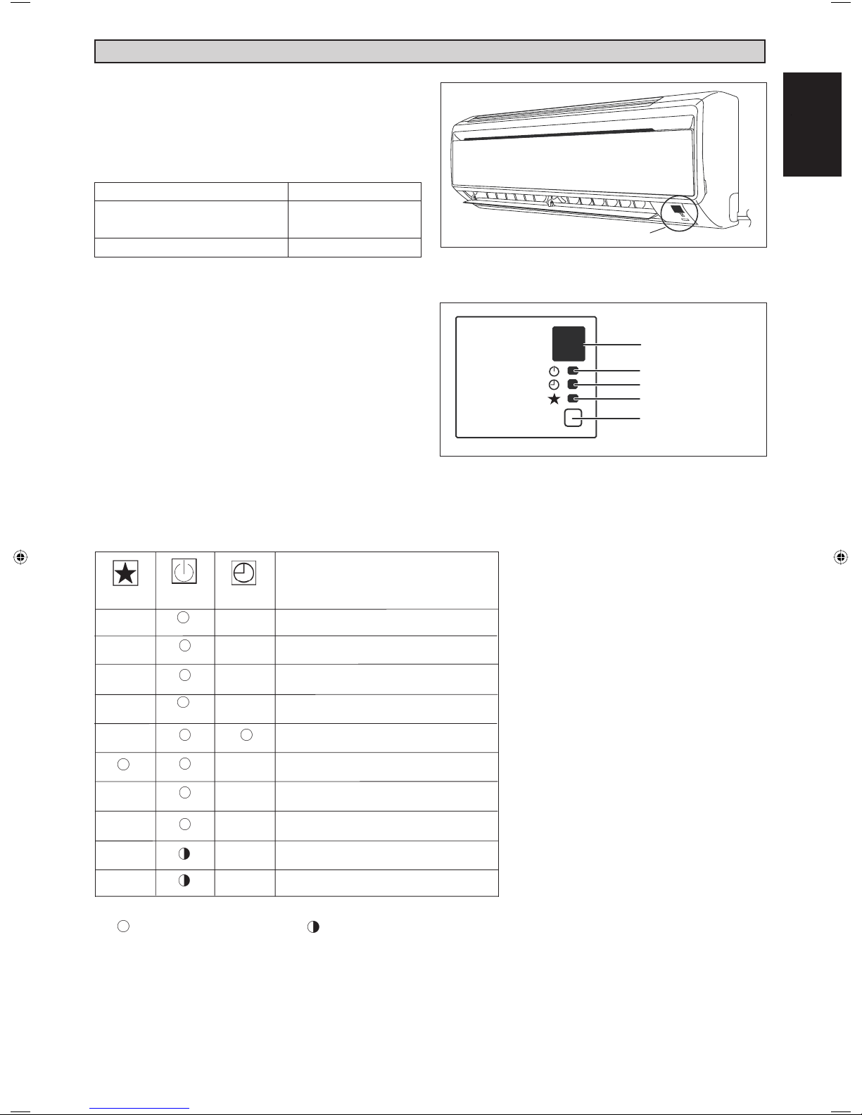
INDICATOR LIGHTS
IR Signal Receiver
When an infrared remote control operating signal has
been transmitted, the signal receiver on the indoor unit
will respond as below to confi rm acceptance of the signal
transmission.
ON to OFF
OFF to ON
Pump down / Cool force on
Others
Cooling Unit / Heat Pump Unit
1 Long Beep
2 Short Beep
1 Short Beep
The table shows the LED indicator lights for the air
conditioner unit under normal operation and fault
conditions. The LED indicator lights are located at the
side of the air conditioner unit.
The heat pump units are equipped with an “auto” mode
sensor whereby it will provide reasonable room
temperature by switching automatically to either “cool”
or “heat” mode according to the temperature set by the
user.
IR Receiver
LED Indicator Lights for Cooling Unit / Heat Pump
Unit
IR Receiver
Cool / Heat
Timer
Sleep
ON/OFF switch
h
s
i
l
g
nE
English
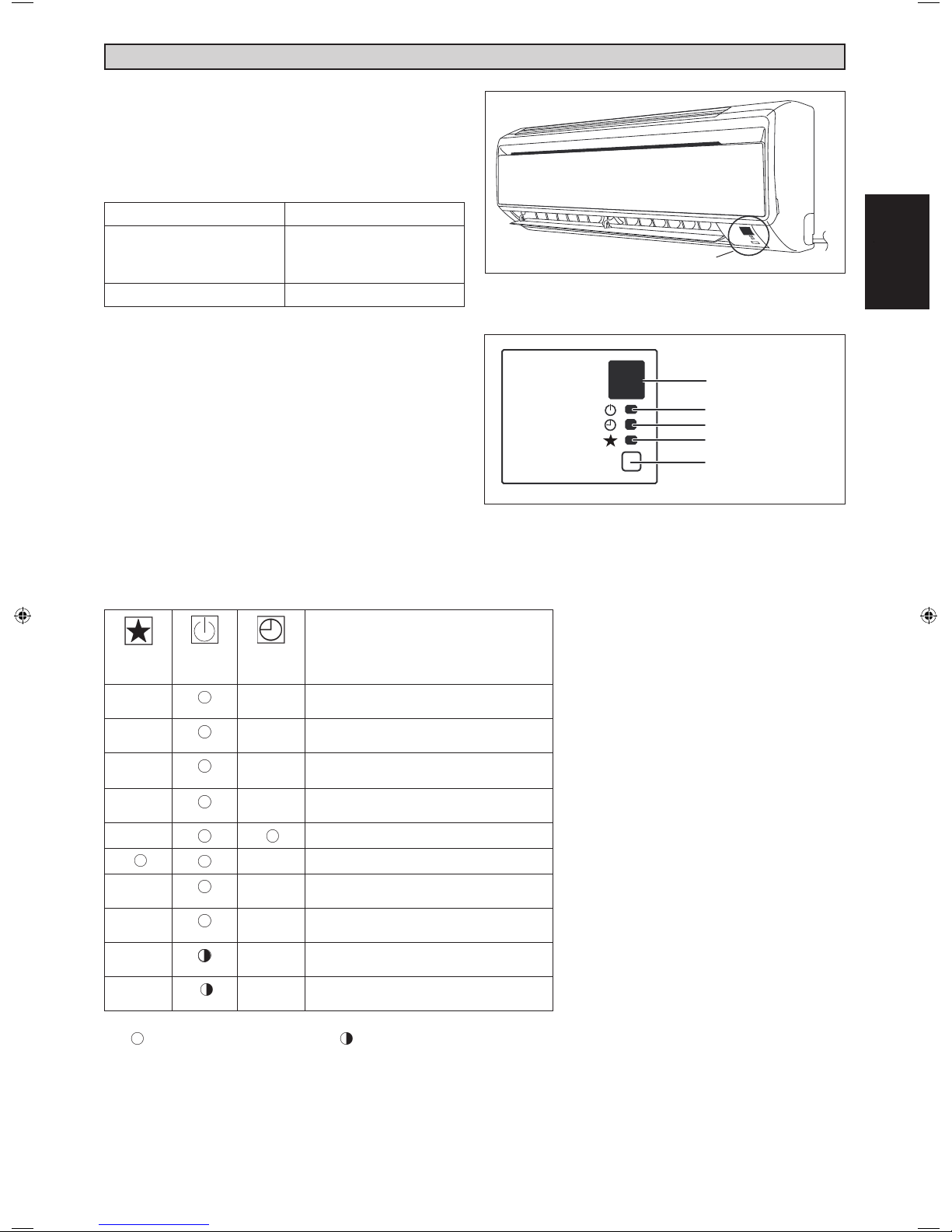
LED Indicator Lights : Normal Operation & Fault Condition For Cooling / Heat Pump Unit
COOL/HEAT
(GREEN/RED)
GREEN
RED
RED
GREEN
Operation
Cool mode
Heat mode
Auto mode in Heating operation
Auto mode in Cooling operation
Timer on
Sleep mode on
GREEN
GREEN
RED
GREEN
Fan mode on
Dry mode on
Defrost operation
Unit error
ON Blinking
1-11
Page 14
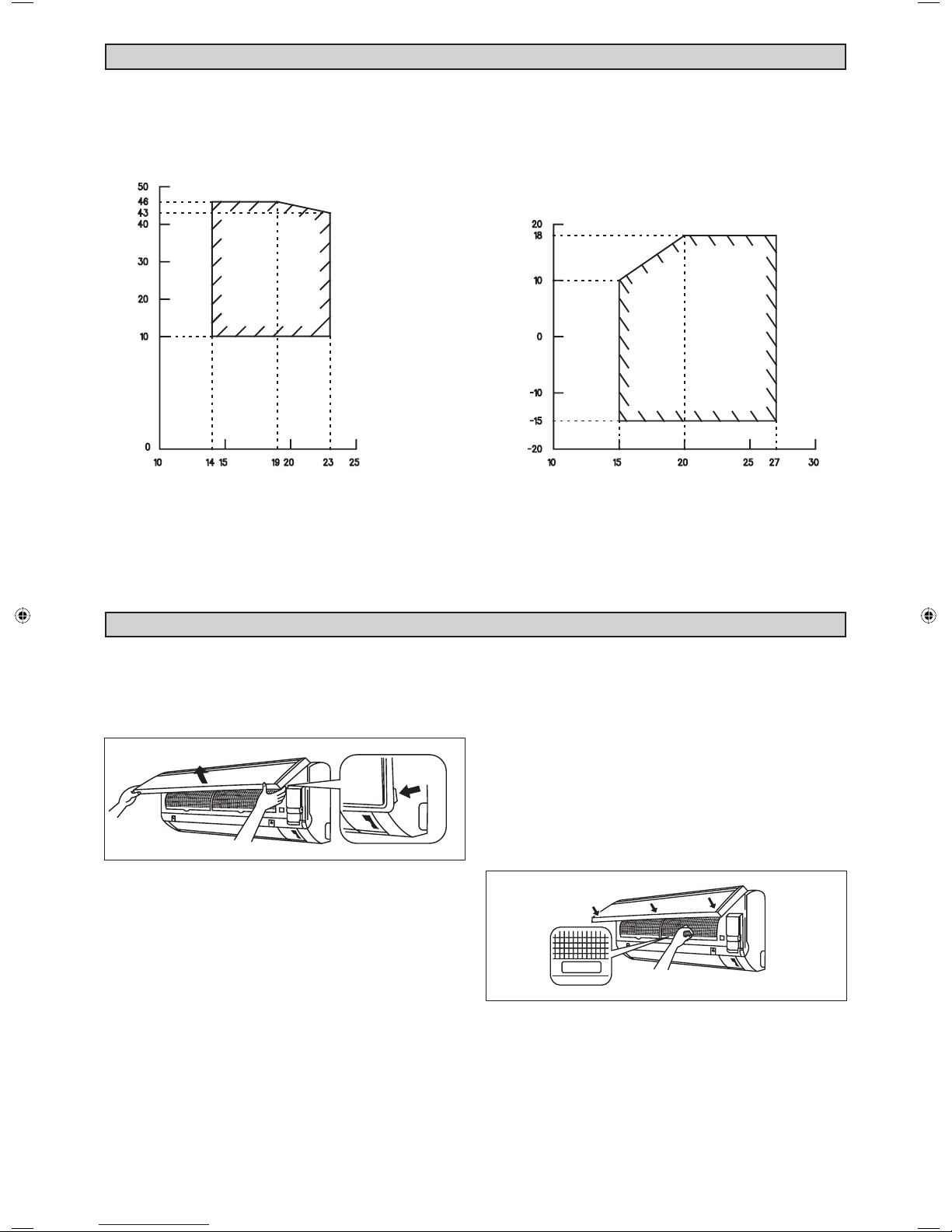
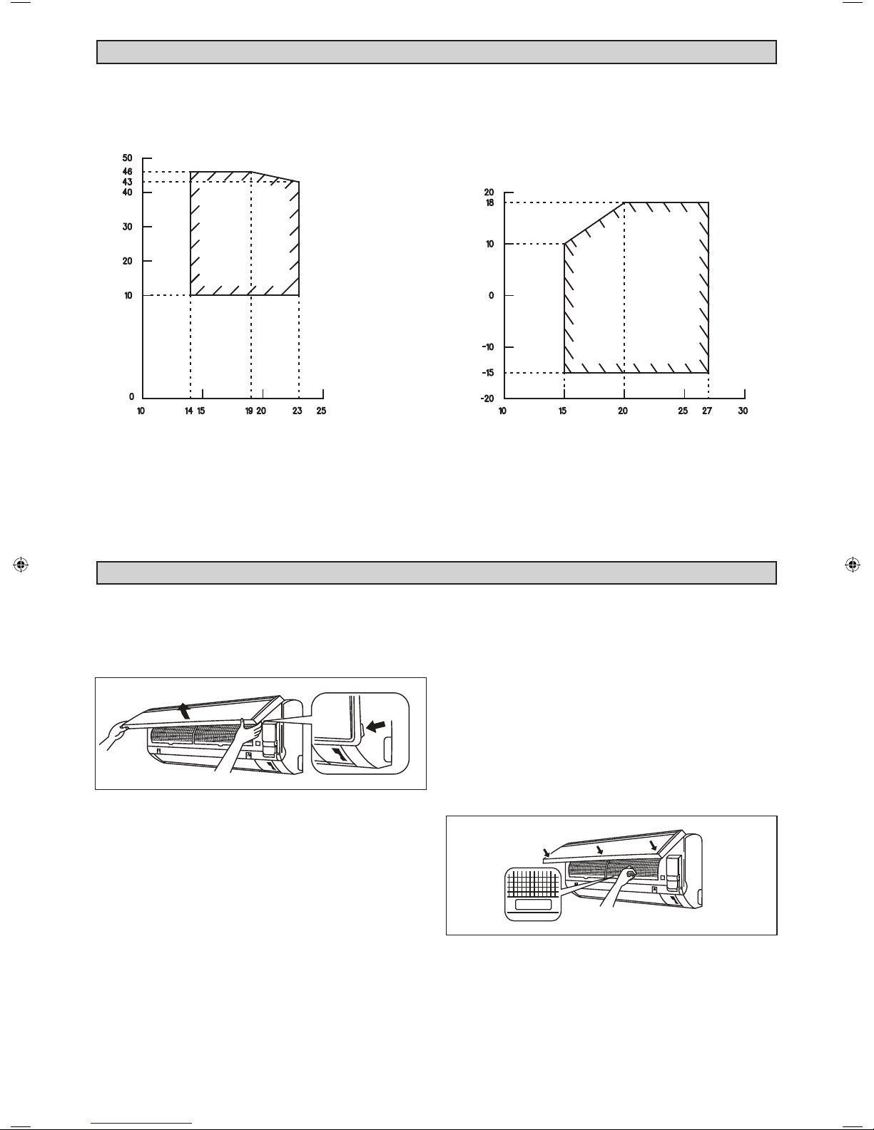
OPERATING RANGE
COOLING HEATING
OUTDOOR TEMP. (°CDB)
INDOOR TEMP. (°CWB) INDOOR TEMP. (°CDB)
AIR FILTER
1. Open the front panel.
• Hold the panel at the recesses on the main unit (2
recesses on right and left sides) and lift it until it
stops.
Process on
main unit
OUTDOOR TEMP. (°CWB)
DB: Dry bulb WB: Wet bulb
3. Clean or replace each fi lter.
• When shaking off remaining water, do not wring the
fi lter.
4. Set the air fi lter and close the front panel.
• Insert claws of the fi lters into slots of the front panel.
Close the front panel slowly and push the panel at
the 3 points. (1 on each side and 1 in the middle.)
• The air fi lter have a symmetrical form in the horizontal
direction.
2. Pull out the air fi lters.
• Push a little upwards the tab at the center of each
air fi lter, then pull it down.
FRONT
1-12
Page 15
SERVICE AND MAINTENANCE
Service Parts
Indoor air fi lter
Indoor unit
1. Remove any dust adhering to the fi lter by using a vacuum cleaner or wash in
lukewarm water (below 40°C/104°F) with a neutral cleaning detergent.
2. Rinse the fi lter well and dry before placing it back onto the unit.
3. Do not use gasoline, volatile substances or chemicals to clean the fi lter.
1. Clean any dirt or dust on the grille or panel by wiping it with a soft cloth
soaked in lukewarm water (below 40°C/104°F) and a neutral detergent
solution.
2. Do not use gasoline, volatile substances or chemicals to clean the indoor
unit.
Maintenance Procedures Period
At least once every 2
weeks.
More frequently if
necessary.
At least once every 2
weeks.
More frequently if
necessary.
CAUTION
• Avoid direct contact of any coil treatment cleaners on plastic part. This may cause plastic part to deform as a
result of chemical reaction.
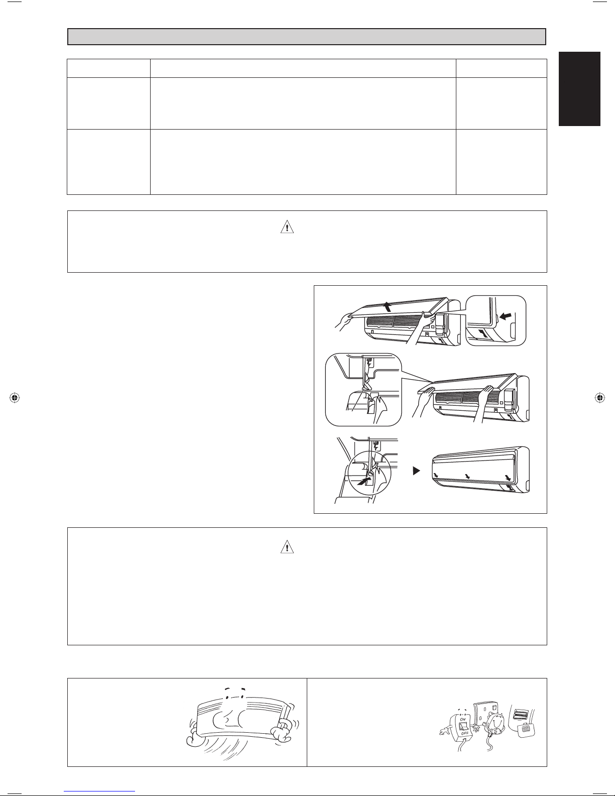
1. Open the front panel.
• Hold the panel at the recesses on the main unit (2
recesses on right and left sides) and lift it until it
stops.
2. Remove the front panel.
• While lifting the front panel further, slide it to the right
and pull it to the front side. The left rotating shaft is
detached. Slide the right rotating shaft to the left and
pull it to the front side to remove it.
3. Attach the front panel.
• Align the right and left rotating shafts of the front
panel with the grooves and push them all the way
in.
• Gently close the front panel. (Push both ends and
the center on the front panel.)
Rotating
shaft
Recess on
main unit
h
s
i
l
g
nE
English
• Do not touch the metal parts of the indoor unit. It may cause an injury.
• When removing or attaching the front panel, support the panel securely with hand to prevent it from falling.
• For cleansing, do not use hot water above 40°C, benzine, gasoline, thinner, nor other volatile oils, polishing
compound, scrubbing brushes, nor other hand stuff.
• After cleaning, make sure that the front panel is securely fi xed.
When The Unit Is Not To Be Used For An Extended Long Period Of Time
Operate the unit for 2 hours
with the following setting.
Operating mode : cool
Temperature : 30°C/86°F
CAUTION
Remove the power plug.
If you are using an independent
electric circuit for your unit, cut
off the circuit.
Remove the batteries in the
remote control.
1-13
Page 16

MEMO
1-14
Page 17
MEMO
h
s
i
l
g
nE
English
1-15
Page 18

MEMO
1-16
Page 19
Unità Interna [Serie M5WMYL]
IL SEGNO MOSTRA LA DIREZIONE DEI TUBI
A
DISEGNI E DIMENSIONI
SINISTRA DESTRA
B
BASSO
DIETRO DIETRO
VISTA DALL’ALTO
IN
FERITOIA DI
AERAZIONE
Punti di ritenzione raccomandati
per la piastra di montaggio
(5 punti in tutto)
VITI INSERITE NELLA GRIGLIA
FRONTALE (ALL’INTERNO)
VISTA FRONTALE
IN
BASSO
RICEVITORE DI
SEGNALE
UNITÀ INTERNA
INTERRUTTORE ON/OFF
TEMPERATURA
AMBIENTE TERMISTORE
(ALL’INTERNO)
Usare la misura del nastro
come posizione che indica
la fi ne del nastro a
D
hs
i
l
g
nE
Italiano
C
B
VISTA LATERALE
E
PIASTRA
MORSETTIERA
CON TERMINALE
A TERRA
Istruzioni originali
F
F
B
Foro nel muro di
Ø 65mm
G
I
Posizione del
tubo di scarico
Modello
G
Dimensioni
J
L
H
Estremità del tubo del liquido Estremità del tubo del gas
LASTRA DI INSTALLAZIONE Tutte le dimensioni sono in mm
M
A
K
ABCDEFGH I JKL M
M5WMY10/15LR 800 288 206 166 184 42 46 55 56 154 182 263 52
2-1
Page 20
Unità Esterna [Serie M5LCY10/15FR]
G
E
F
D
A
B C
IH
Tutte le dimensioni sono in mm
N
J
LK
Dimensioni
Modello
ABCDEFGH I J K LMN
M5LCY10/15FR 550 658 51 11 273 16 14 470 96 299 94 60 14 133
2-2
Page 21
MANUALE D’INSTALLAZIONE
Il presente manuale descrive come procedere all’installazione del condizionatore per assicurarne il corretto
funzionamento in condizioni di sicurezza.
Degli adattamenti possono rivelarsi necessari per rispondere a particolari esigenze locali.
Prima di utilizzare il condizionatore, leggere attentamente le presenti istruzioni. Conservarle per ogni evenienza
futura.
Questo apparecchio è destinato a essere utilizzato da personale esperto o adeguatamente formato per l’industria
leggera o in negozi o aziende agricole oppure da persone non qualifi cate per applicazioni commerciali.
NORME DI SICUREZZA
AVVERTENZA
• L’installazione e la manutenzione devono essere
eseguite da personale qualifi cato, competente in
questo genere di apparecchi e al corrente delle leggi e
regolamenti in vigore.
• Tutti gli allacciamenti elettrici devono essere eseguiti
conformemente alla regolamentazione elettrica in
vigore.
• Prima di procedere agli allacciamenti secondo lo schema
elettrico presentato più avanti, accertarsi che il voltaggio
dell’apparecchio corrisponda a quello della rete.
• Dotare il condizionatore di una presa di TERRA al fi ne
di prevenire i rischi originati da eventuali defi cienze del
sistema di isolamento.
• Evitare che i fi li elettrici tocchino le tubazioni frigorifere o
un qualsiasi organo rotante dei motori del ventilatore.
• Prima di installare il condizionatore o di procedere ad
interventi di manutenzione, accertarsi che sia spento
(OFF).
• Togliete sempre la corrente prima di effettuare la
manutenzione del condizionatore.
• NON rimuovere il cavo di alimentazione quando il
condizionatore è acceso. Questo può causare seri
shock elettrici e pericolo d’incendio.
• Mantenere l’unità interna e quella esterna, il cavo di
alimentazione e il cablaggio di trasmissione ad almeno
1m di distanza da TV e radio, per evitare immagini
distorte e scariche statiche. {A seconda del tipo e
sorgente di onde elettriche, si possono sentire scariche
statiche anche a più di 1m di distanza}.
Durante l’installazione, verifi care accuratamente
i punti seguenti.
• Non procedere all’installazione in luoghi dove possano
verifi carsi fughe di gas.
Le perdite di gas accumulatesi intorno all’unità
• Verifi care che i condotti di drenaggio siano stati
Un’installazione incorretta può causare delle perdite
• Non sovraccaricare il condizionatore.
L’apparecchio è precaricato in fabbrica. Qualsiasi
• Dopo l’installazione o gli interventi di manutenzione
Una difettosa chiusura del pannello è causa di
• Per preservarsi da eventuali ferite, evitare di toccare gli spigoli
• Prima di spegnere l’apparecchio, impostare l’interruttore
• Non installare le unità accanto o in prossimità dell’entrata.
•
• Se l’unità viene posizionata in cucina, tenere lontana la farina
• Questa unità non è adatta a stabilimenti in cui sono presenti
• Non installare le unità accanto a sorgenti termali o in raffi nerie di
• Accertarsi che i colori dei fi li dell’unità esterna corrispondano ai
• IMPORTANTE : NON INSTALLARE O UTILIZZARE IL
• Non usare fi li congiunti e intrecciati per l’alimentazione in
• Per qualsiasi richiesta di parti di ricambio, contattare un
• L’apparecchio non deve essere utilizzato in atmosfere
possono causare degli incendi.
correttamente installati.
d’acqua e danneggiare il mobilio.
sovraccarico provoca una sovracorrente e può
danneggiare il compressore.
accertarsi di rimettere a posto il pannello di chiusura.
rumori durante il funzionamento.
affi lali e la superfi cie della serpentina.
ON/OFF del telecomando sulla posizione “OFF” in modo
da evitare l’apertura nociva dell’unità. In caso contrario, le
ventole dell’unità iniziano a ruotare automaticamente quando
si riaccende l’apparecchio, causando pericoli di lesioni al
personale di servizio ed agli utenti.
Non utilizzare apparecchiature di riscaldamento nelle immediate
vicinanze del condizionatore e non utilizzare il condizionatore
in ambienti in cui sono presenti olio minerale o vapori d’olio
perché le parti in plastica potrebbero sciogliersi o deformarsi a
causa del calore eccessivo o in seguito a una reazione chimica.
dall’unità per evitare che venga aspirata dall’unità stessa.
vapori di olio da taglio o polveri di ferro o in cui la tensione di
alimentazione è soggetta a forti fl uttuazioni.
petrolio dove sono presenti gas solforosi.
contrassegni dei morsetti dell’unità interna.
CONDIZIONATORE D’ARIA IN UNA ZONA LAVANDERIA.
ingresso.
rivenditore autorizzato.
potenzialmente esplosive.
CAUTELA
hs
i
l
g
nE
Italiano
Specifi che di smaltimento
Il climatizzatore è contrassegnato con questo simbolo, ciò signifi ca che i prodotti elettrici ed elettronici non possono essere
smaltiti insieme ai rifi uti domestici non differenziati.
Non cercare di demolire il sistema da soli: la demolizione del sistema di condizionamento, nonché il recupero del refrigerante, dell’olio e di
qualsiasi altra parte devono essere eseguiti da un installatore qualifi cato in conformità alla legislazione locale e nazionale vigente in materia.
I climatizzatori devono essere trattati presso una struttura specializzata nel riutilizzo, riciclaggio e recupero dei materiali. Il corretto smaltimento
del prodotto eviterà le possibili conseguenze negative all’ambiente e alla salute dell’uomo. Per maggiori informazioni contattare l’installatore
o le autorità locali.
Le batterie devono essere tolte dal telecomando e smaltite separatamente conformemente alla legislazione locale e nazionale
vigente in materia.
AVVISO
2-3
Page 22

IMPORTANTE
Informazioni importanti sul refrigerante utilizzato
Questo prodotto contiene gas fl uorinati ad effetto serra inclusi nel protocollo di Kyoto.
Non liberare tali gas nell’atmosfera.
Tipo di refrigerante: R410A
Valore GWP
(1)
GWP = potenziale di riscaldamento globale
Compilare con inchiostro indelebile,
■ A la carica di refrigerante di fabbrica del prodotto,
■ B la quantità di refrigerante aggiuntiva nel campo e
■ A + B la carica di refrigerante totale
sull’etichetta di carica del refrigerante fornita con il prodotto.
L’etichetta compilata deve essere collocata in prossimità della porta di carica del prodotto (ad esempio, all’interno del
coperchio di ispezione).
(1)
: 1975
1 carica di refrigerante di fabbrica del prodotto:
vedi targhetta con il nome dell’unità
(2)
2 quantità di refrigerante aggiuntiva nel campo
3 carica di refrigerante totale
4 contiene gas fl uorurati ad effetto serra disciplinati dal Protocollo di Kyoto
5 unità esterna
6 cilindro del refrigerante e collettore di carica
(2)
Se sono presenti sistemi con più unità interne, applicare una sola etichetta*, indicante la carica totale di refrigerante
eseguita in fabbrica di tutte le unità interne collegate al sistema refrigerante.
È possibile che siano necessarie ispezioni periodiche per controllare eventuali perdite di refrigerante secondo le
normative locali e/o europee. Per informazioni più dettagliate, contattare il rivenditore locale.
* sull’unità esterna
2-4
Page 23
SCHEMA DI INSTALLAZIONE
Unità Interna
Pannello anteriore
50mm o più dalle pareti (su
entrambi i lati)
Filtri d’aria
Unità Esterna
M4 X 12L
30mm o più dal soffi tto
Sportellino di manutenzione
• Apertura del coperchio di servizio
Il coperchio di servizio può
essere aperto/chiuso.
• Metodo di apertura
1) Rimuovere le viti del
coperchio di servizio.
2) Estrarre il coperchio di
accesso per assistenza tecnica
spostandolo verso il basso e in
diagonale, nella direzione della
freccia.
3) Tirare verso il basso.
Stuccare
lo spazio
del foro del
tubo con
stucco da
legno.
250mm dalla parete
Tagliare il tubo di isolamento
termico a una lunghezza
appropriata e avvolgerlo con
nastro, accertandosi che non ci
siano buchi nella linea di taglio
del tubo di isolamento.
Avvolgere il tubo di isolamento da
cima a fondo con nastro di fi nitura.
hs
i
l
g
nE
Italiano
INSTALLAZIONE DELL’UNITÀ ESTERNA
• Nei casi in cui una parete o un altro ostacolo impedissero il passaggio del fl usso d’aria in ingresso o in uscita dall’unità esterna,
seguire le seguenti istruzioni di installazione.
• Per ognuno degli schemi di installazione seguenti, l’altezza massima del lato di uscita deve essere pari a 1200mm.
Parete su un lato Parete sui due lati
Più di 50 Più di 100
Più di 150
Più di 100
Massimo
1.200
Vista laterale
Più di 50
Vista dall’alto
Più di 50
Parete sui tre lati
Più di 150
Più di 50
Più di 300
Vista dall’alto
unità: mm
2-5
Page 24
Operazioni di scarico. (Solo Per Le Versioni In Pompa Di Calore)
1) Per eseguire le operazioni di scarico utilizzare l’apposito tappo.
2) Se il foro di drenaggio viene coperto da un supporto di montaggio o da
una superfi cie, aggiungere ulteriori basi con un’altezza minima di 30mm
da posizionare sotto i piedini dell’unità esterna.
3) In zone fredde non utilizzare tubo di scarico con l’unità esterna.
(Altrimenti, l’acqua di scarico potrebbe gelarsi, impedendo un buon
funzionamento del sistema di riscaldamento.)
INSTALLAZIONE DELL’UNITÀ INTERNA
L’unità interna deve essere installata in modo da evitare
la cortocircuitazione tra il fl usso d’arua fredda in uscita e
l’arua di ritorno. Assicurarsi di mantenere le distanze di
rispetto/sicurezza illustrate nella fi gura. Installare l’unità
interna in modo che non si trovi ad ess ere direttamente
esposta ai raggi del sole o in prossimità di porte e fi nestre.
Questa disposizione è la migliore anche per le tubazioni
e il sistema di drenaggio.
Le tubazioni del refrigerante possono essere collegate
in differenti modi (lato posteriore destro o sinistro)
utilizzando i fori predisposti sul rivestimento esterno.
Piegare accuratamente i tubi nel verso richiesto per
condurli al foro appropriato. Per i laterali e la parte
inferiore, prendere la base della tubazione e collocarla
nella direzione richiesta. Utilizzado del nastro adesivo,
fi ssarve quindi insieme il tubo di drenaggio.
Tubo di scarico dell’acqua
Telaietto inferiore
Tappo di scarico
Tubo (disponibile in commercio,
diam. interno 16mm)
Flusso
d’aria
(All’interno)
min. 50 min. 50
(Spazio per la
manutenzione)
Spazio necessario
Tutte le dimensioni sono in mm
(Spazio per la
manutenzione)
(Spazio per le
min. 30
Tubazione laterale-destra, posteriore-destra o
inferiore-destra
prestazioni)
Tubazione sul
lato destroy
Rimuovere il coperchio
dell’attacco del tubo in questo
punto, in caso di tubazione sul
lato destro
Rimuovere il coperchio dell’attacco
del tubo in questo punto, in caso di
tubazione sul lato destro inferiore
Tubazione sul
latodestro inferiore
Tubazione laterale-sinistra, posteriore-sinistra o
inferiore-sinistra
Rimuovere il coperchio dell’attacco del tubo
in questo punto, in caso di tubazione sul
lato sinistro inferiore
Tubazione sul lato
sinistro inferiore
Tubazione sul latodestro
posteriore
Legare insieme il tubo
di raffreddamento e
il tubo fl essibile di
scarico con nastro
isolante.
Rimuovere il coperchio
dell’attacco del tubo in
questo punto, in caso
di tubazione sul lato
sinistr
Tubazione sul lato
sinistro
Tubazione sul lato
sinistro inferiore
2-6
Page 25
Montaggio Della Staffa Di Supporto
Accertarsi della capacità di tenuta della parete. Se il muro
non è in grado di sopportare il peso dell’apparecchio,
rinforzarlo con delle piastre o dei pilastrini di sostegno.
Per il montaggio orizzontale, utilizzare il livello, Fissare
con 5 viti appropriate.
Nel caso in cui le tubazioni posteriori fuoriescano, praticare
sul muro un foro di 65mm di diametro servendosi di una
perforatrice a cono. Il foro deve presentare all’esterno una
leggera inclinatura verso il basso (veder fi gura).
Piastra di montaggio
Vite di fi ssaggio della
piastra d’installazione
Punti Di Fissaggio Della Piastra Di Montaggio E
Dimensioni Raccomandate
Come Fissare L’unità Interna
Agganciare le griffe del telaio inferiore alla piastra di
montaggio.
Come Rimuovere L’unità Interna
Spingere in alto fi no all’parea contrassegnata (nella parte
inferiore della griglia frontale) per rilasciare gli artigli.
Piastra di montaggio
Fermo
Telaietto inferiore
Griglia anteriore
Appendere qui il gancio dell’unità interna.
Segno (parte
posteriore)
hs
i
l
g
nE
Italiano
Punti di ritenzione
raccomandati per la piastra di
montaggio (5 punti in tutto)
166
2.24
882
9.54
153.8
263
Estremità del tubo del liquido Estremità del tubo del ga
Usare la misura del nastro come
posizione che indica la fi ne del
nastro a
51.9
800
181.7
184
55.554.5
2.24
Foro nel
muro di
Ø 65mm
9.54
Posizione
del tubo di
scarico
Tutte le dimensioni sono in mm
Foro Con Perforatrice A Cono
Tubo incassato nel muro
(A fornitura locale)
Coperchio per il
foro nel muro
(A fornitura locale)
EsternoInterno
Stuccatura
Ø 65
Tubo incassato nel muro
(A fornitura locale)
Montaggio Dell’unità
Agganciare l’unità alla parte superiore della staffa
(Inserire i due ganci posteriori dell’unità negli appositi
fori della staffa). Per controllare se gli agganci sono
correttamente inseriti nella piastra d’installazione,
spostare l’unità leggermente verso destra e sinistra.
Piastra di
Quando si spelano in
anticipo le estremità dei
fi li di interconnessione,
unire le estremità
destre dei fi li con nastro
isolante.
Guida per i fi li
montaggio
Fili di
interconnessione
Tubo Di Scarico Condensa
Il tubo di drenaggio interno deve essere posizionato in
leggera pendenza per garantirne un buon funzionamento.
Evitare condizioni che possono causare perdite d’acqua.
Drenaggio Dell’acqua
Ritenzione
dell’acqua
Perdite di
liquido
Corretto Errato Errato Errato
Perdite di
liquido
Perdite di
liquido
Il tubo
pesca
nell’acqua
Drenaggio
CAUTELA
• Non installare l’unità interna o esterna a
un’altitudine superiore a 2000m.
2-7
Page 26
COLLEGAMENTI FRIGORIFERI
Lunghezza Consentita Dei Condotti Del
Refrigerante
Se le tubazioni sono troppo lungfi e, la capacità e
l’affi dabilità dell’apparecchio risultano entrambe
compromesse. Maggiore è il numero dei gomiti, maggiore
è la resistenza al fl usso del sistema di raffreddamento. In
tale situazione, le capacità di raffreddamento diminuiscono
e l’attività del compressore può ridursi fi no a diventare
ineffi cace. Scegliere sempre il percorso più breve e
attenersi alle indicazioni fornite nella tabella che segue:
Modello 10 15
Minima lunghezza consentita, m
Massima lunghezza consentita, m
Carica aggiuntiva di refrigerant
Massima elevazione consentita, m
Dimensioni tubo del gas, mm/
3
15
20
10
9,52 (3/8")
(pollici)
Dimensioni tubo del liquido, mm/
6,35 (1/4")
(pollici)
* Accertarsi di aggiungere la quantità corretta di refrigerante
aggiuntivo. In caso contrario si potrebbe riscontrare una
riduzione delle prestazioni.
A
ttenzione:
Il refrigerante precaricato in fabbrica è calcolato
per una tubatura di 7,5m di lunghezza.
Tubazioni e Svasatura
• Non utilizzare condotti di rame contaminati o danneggiati.
Se una tubazione, un evaporatore o un condensatore sono
stati esposti o aperti per 15 secondi o più, mettere in vuoto
il sistema. In generale, non rimuovere le parti in plastica, i
tappi in gomma e i dadi di ottone da valvole, accessori vari,
condutture e serpentine fi no a quando non si è pronti a
collegare le tubazioni di aspirazione e del liquido a valvole
ed eventuali accessori.
• Se sono necessari degli interventi di brasatura, assicurarsi
di passare l’azoto sulla batteria e sui giunti mentre si esegue
l’intervento. Ciò eviterà la formazione di fuliggine sulla parete
interna dei tubi di rame.
agliare il tubo pezzo per pezzo, facendo avanzare
• T
lentamente la lama del tagliatubi. Una forza eccessiva o un
taglio profondo causerebbero un’ulteriore distorsione del tubo
con conseguente ulteriore bavatura. Vedere fi gura A.
•
Rimuovere le bavature dall’estremità del tubo utilizzando
l’apposito attrezzo. Vedere fi gura B. Afferrare la parte superiore
del tubo e posizionare l’attrezzo per l’eliminazione delle sbavature
in basso per evitare che le limature metalliche penetrino
all’interno del tubo. Ciò eviterà la presenza di irregolarità sui lati
svasati che potrebbe causare fuoriuscita di gas.
• Inserire sui tubi di rame i dadi svasati che si trovano sulle
bocchette di ingresso delle unità interna ed esterna.
• La lunghezza esatta del tubo che fuoriesce dalla superfi cie
superiore dello stampo di svasatura è determinata
dall’allargatubi. Vedere fi gura C.
• Fissare saldamente il tubo sullo stampo di svasatura. Far
corrispondere la parte centrale dello stampo di svasatura
con quella del punzone di svasatura e stringere quest’ultimo
completamente.
• Il collegamento delle tubazioni refrigeranti è isolato da
poliuretano a cellule chiuse.
• Mentre si stringe il dado svasato con la chiave torsiometrica,
assicurarsi che la direzione sia quella indicata dalla freccia
sulla chiave.
• Il collegamento delle tubazioni refrigeranti è isolato da
poliuretano a cellule chiuse.
Dimensioni del tubi, mm / (pollici)
ChiaveRsiometrica, Nm/(ft-lb)
6,35 (1/4") 18 (13,3)
9,52 (3/8") 42 (31,0)
12,70 (1/2") 55 (40,6)
15,88 (5/8") 65 (48,0)
19,05 (3/4") 78 (57,6)
Figura A
Taglio Del Tubo Di Rame
1/4t
Figura B
Togliere Sbavatura Dal Tubo
Figura C
Estremità Rastremata
Tubo Di Rame
D
A
Ø Tubo, D A (mm)
Pollici mm Imperiale
(Tipo Con
Galletto)
1/4"
3/8"
1/2"
5/8"
3/4"
Figura D
6,35 1,3 0,7
9,52 1,6 1,0
12,70 1,9 1,3
15,88 2,2 1,7
19,05 2,5 2,0
Giunto Svasato Tubo Svasato
Tubature Interne
Rigido
(Tipo A
Innesto)
Dadi Di Svaso
Collegamento Delle Tubazioni Alle Unità
• Allineare le tubature e stringere a mano il dado quanto basta.
Vedere la fi gura D.
• A mezzo di una chiave torsiometrica, stringere quindi il dado
fi no a che si produca lo scatto previsto.
2-8
Chiave Fissa
Chiave Torsiometrica
Page 27
COLLEGAMENTI ELETTRICI
IMPORTANTE :* I valori sopra indicati hanno solo un carattere indicativo. Devono quindi essere verifi cati e scelti
in modo da rispondere alle leggi vigenti e ai regolamenti locali. Inoltre, dipendono pure dal tipo di
impianto e dai conduttori utilizzati.
**
L’appropriato intervallo di tensione deve essere confrontato con i dati della targa dell’apparecchio.
Morsettiera Dell’Unità
Interna
1
2
SIG
N
L
Nell’impianto elettrico è necessaria
un’interruzione onnipolare
dell’alimentazione con contatti
separati da almeno 3mm.
Morsettiera Dell’Unità
Esterna
1
2
SIG
Cavo Di
Alimentazione
Voltaggi ammessi** 220V - 240V / 1Ph / 50Hz+
Dimensioni del cavo
di alimentazione* mm²
Numero di anime
Dimensioni del cavo
di interconnessione* mm²
Numero di anime
Fusibile di ritardo consigliato A 15 15
*
Se la lunghezza del cavo supera i 2m, utilizzarne uno di
1,5
1,5
3
1,5
1,5
4
maggiori dimensioni.
3
4
• Tutti i fi li devono essere collegati saldamente.
• Accertarsi che i fi li non tocchino i condotti del refrigerante, il compressore o qualsiasi organo rotante.
• I cavi di collegamento tra l’unità interna e l’unità esterna devono essere fi ssati utilizzando il dispositivo di ancoraggio
dei cavi in dotazione.
• Il cavo di alimentazione deve equivalere ad un minimo di H07RN-F.
• Accertarsi di non applicare pressioni esterne sui fi li e sui connettori dei terminali.
• Accertarsi che tutti i coperchi siano fi ssati adeguatamente per evitare la presenza di buchi.
• Utilizzare un terminale a crimpare rotondo per collegare i cavi alla morsettiera dell’impianto elettrico. Collegare i
cavi facendo corrispondere le indicazioni sulla morsettiera. (Consultare lo schema elettrico in dotazione con l’unità.)
Modello 10 15
hs
i
l
g
nE
Italiano
• Utilizzare un cacciavite adatto per serrare le viti del terminale. Cacciavite non adatti possono danneggiare la testa
delle viti.
• Serrare eccessivamente le viti del terminale può danneggiarle.
• Non collegare fi li di misuratori diversi allo stesso terminale.
• Tenere i fi li in modo ordinato. Evitare che i fi li possano bloccare altre parti o il coperchio della scatola di derivazione.
Collegare fi li dello
stesso misuratore ai
due lati.
Applicare la guaina isolante
Terminale a crimpare rotondo
Non collegare i
fi li dello stesso
misuratore da un lato.
2-9
Filo elettrico
Non collegare fi li di
misuratori diversi.
Page 28
PRECAUZIONI SPECIALI PER L’UTILIZZO DI R410A
• Usi gli attrezzi ed i materiali esclusivamente per
R410A è un nuovo refrigerante di HFC che non
danneggia lo strato di ozono. La pressione di esercizio
di questo nuovo refrigerante è 1.il refrigerante 6 volte
più superiore convenzionale (R22), così installation/
servicing adeguato è essenziale.
• Non utilizzare mai un refrigerante diverso da R410A in
un condizionatore d’aria progettato per funzionare con
R410A.
• L’olio di POE o PVE usato come lubrifi cante per il
compressore R410A è diverso dall’olio minerale
usato per il compressore R22. Durante installazione
o l’assistenza, la precauzione supplementare deve
essere presa per non esporre il sistema di R410A
troppo lungo ad aria umida. L’olio residuo di POE o
PVE nelle condutture e nei componenti può assorbire
l’umidità dell’aria.
• Impedire mischarging, il diametro dell’orifi cio di servizio
il refrigerante R410A. Gli attrezzi esclusivamente
per R410A sono valvola molteplice, tubo fl essibile
caricantesi, manometro, rivelatore della perdita
del gas, attrezzi del chiarore, chiave da coppia di
torsione, pulsometro e cilindro del refrigerante.
• Poichè un condizionatore dell’aria di R410A subisce
l’più alta pressione che le unità R22, è essenziale per
scegliere correttamente i tubi di rame. Mai diluente di
rame dei tubi dell’utente che 0,8mm anche se sono
disponibili nel mercato.
•
Se il gas del refrigerante propaga durante l’installazione/
servicing, sia sicuro arieggiare completamente. Se il gas
refrigerant entra in contatto con fuoco, un gas tossico
può accadere.
• Nell’installare o rimuovendo un condizionatore
dell’aria, non lasci che l’aria o l’umidità rimanga nel
ciclo refrigerant.
sulla valvola del chiarore è differente da quello di R22.
VUOTO E CARICA
La messa in vuoto è necessaria per eliminare tutta l’umidità e l’aria dal sistema.
Messa In Vuoto Delle Tubazioni E Dell’unità
Interna
Fatta eccezione dell’unità esterna che è precaricata, l’unità
interna e le tubature di collegamento devono essere spurgate
dell’aria. Essa contiene infatti dei residui di umidità prodotti
dal ciclo di raffreddamento che possono provocare un
malfunzionamento del compressore.
• Rimuovere i tappi della valvola e dell’attacco di servizio.
• Collegare il centro della valvola di carico alla pompa di
estrazione.
• Collegare la valvola di carico alla bocchetta di servizio della
valvola a 3 vie.
• Avviare la pompa di estrazione. Far spurgare per 30 minuti
circa. Il tempo di spurgo varia a seconda della capacità della
pompa di estrazione. Controllare che l’ago della valvola del
collettore si sia portata su -760mmHg.
Bocchetta Di Servizio
MANOMETRO DI BASSA PRESSIONE
Brugola
MANOPOLA LO
Attenzione
• Se l’ago non si sposta su -760mmHg, controllare che non
ci siano perdite di gas (utilizzando il rivelatore di fughe) in
prossimità tra unità interna ed esterna ed esterno e riparare
la perdita prima di procedere.
• Chiudere la valvola di carico e spegnere la pompa di
estrazione.
• Sull’unità esterna, aprire la valvola di aspirazione a 3 vie e
la valvola per il liquido a due vie in senso anti-orario con una
brugola di 4mm.
TUBO FLESSIBILE DI CARICO
Operazioni Di Carica
Tale operazione deve essere obbligatoriamente effettuata
utlizzando la borbala del gas ed una bilancia di precisione. Il
gas refrigerante viene introdotto nell’unità esterna tramite la
bocchetta di servizio della valvola aspirante.
• Rimuovere il tappo della bocchetta di servizio.
• Collegare il collettore a bassa pressione alla bocchetta di
aspirazione del serbatoio cilindrico e chiudere il collettore
ad alta pressione. Spurgare l’aria dal tubo fl essibile.
• Mettere in funzione il condizionatore.
• Aprire il cilindro del gas e la valvola del collettore a bassa
pressione.
• Quando la quantità richiesta di refrigerante è stata pompata
nell’impianto, chiudere la valvola del collettore a bassa
pressione e la valvola del cilindro del gas.
• Scollegare il tubo fl essibile dalla bocchetta di servizio
Rimettere il tappo della bocchetta di servizio.
MANOMETRO DI BASSA PRESSIONE
MANOPOLA LO
TUBO FLESSIBILE DI CARICO
-760mmHg
VALVOLA
PER
IL LIQUIDO
VALVOLA DEL
GAS (A 3 VIE)
-760mmHg
VALVOLA
PER
IL LIQUIDO
VALVOLA DEL
GAS (A 3 VIE)
Dadi di
Condotti Del Refrigerante
svaso
Valvola a 3 vie dell’unità esterna
MANOMETRO DI ALTA PRESSIONE
COLLETTORE CON MANOMETRO
MANOPOLA HI (SEMPRE CHIUSA)
TUBO FLESSIBILE DI CARICO
A DAT TAT O RE
POMPA DI
ESTRAZIONE
ANTI CONTROFLUSSO
VALVOLA
DI NON
RITORNO
CONFIGURAZIONE SPURGO
DELL’ARIA CON CARICA
MANOMETRO DI ALTA PRESSIONE
COLLETTORE CON MANOMETRO
MANOPOLA HI (SEMPRE CHIUSA)
TUBO FLESSIBILE DI CARICO
VALVOLA
DI NON
RITORNO
CONFIGURAZIONE SPURGO
DELL’ARIA CON CARICA
2-10
Page 29
SPIE DI CONTROLLO
Ricevitore A Infrarossi
Quando si trasmette un segnale operativo dal
telecomando ad infrarossi, il ricevitore di segnali sull’unità
interna risponderà nel modo di cui sotto per confermare
l’accettazione della trasmissione del segnale.
da ON a OFF 1 Segnale Bip Lungo
da OFF a ON
Pompa non attiva / Potenza
2 Segnale Bip Breve
Ricevitore Infrarossi
di raffreddamento attiva
Altri 1 Segnale Bip Brev
Spie Luminose “LED” Dell’unità Di Raffreddamento /
Riscaldamento
Raffreddamento / Riscaldamento
La tabella che segue indica la funzione della diverse spie
di controllo del condizionatore come pure gli interventi
da effettuare in caso di guasto. Le luci di indicatore del
LED sono situate alla metà dell’unità del condizionatore
dell’aria.
I condizionatori provvisti di pompa di calore sono dotati di
una modalità “automatica” che, alternando automaticamente
Ricevitore Infrarossi
Raffreddamento /
Riscaldamento
Timer
Sospensione
Interruttore ON/OFF
tra modalità “freddo” e “caldo”, assicura una temperatura
ambiente confortevole, in corrispondenza della temperatura
impostata dall’utente.
Spie Luminose “LED” : Funzionamento Normale Per l’unità Di raffreddamento / Riscaldamento
RAFFREDDISI/
CALORE
(VERDE/
ROSSO)
Funzionamento
hs
i
l
g
nE
Italiano
VERDE
ROSSO
ROSSO
VERDE
Raffreddamento
Riscaldamento
Riscaldamento automatic
Raffreddamento automatico
Accensione temporizzatore
Accensione modalità riposo
VERDE
VERDE
ROSSO
VERDE
Modo “Fan” inserito
Modo “Dry” inserito
Sbrinamento
Errore dell’unità
ACCESO Lampeggiante
2-11
Page 30
RANGE DI FUNZIONAMENTO
RAFFREDDAMENTO RISCALDAMENTO
TEMP. ESTERNA (°CDB)
TEMP. INTERNA (°CWB) TEMP. INTERNA (°CDB)
FILTRO DELL’ARIA
1. Aprire il pannello anteriore.
• Tenere il pannello sulle parti rientranti dell’unità
principale (2 parti rientranti sui lati destro e
sinistro) e sollevarlo fi nché si blocca.
Parte rientrante
sull’unità principale
TEMP. ESTERNA (°CWB)
DB: Bulbo secco WB: Bulbo umido
3. Pulire o sostituire ciascun fi ltro.
•
Quando si rimuove l’acqua rimanente, non strizzare
il fi ltro.
4. Collocare il fi ltro dell’aria e chiudere il pannello
anteriore.
•
Inserire i ganci dei fi ltri nelle asole del pannello
anteriore. Chiudere il pannello anteriore lentamente
e spingerlo nei 3 punti. (1 su ciascun lato e 1 al
centro.)
• Il fi ltro dell’aria ha forma simmetrica in direzione
orizzontale.
2. Estrarre i fi ltri dell’aria.
• Spingere leggermente le linguette al centro di ciascun
fi ltro dell’aria verso l’alto, quindi abbassarle.
FRONT
2-12
Page 31

PULIZIA E MANUTENZIONE
Componenti Procedure Di Manutenzione Periodo
Almeno due volte al
mese.
Più spesso se
necessario.
Almeno due volte al
mese.
Più spesso se
necessario.
Filtro dell’aria
interno
Unità interna
1. Togliere la polvere dal fi ltro usando un’aspirapolvere o lavarlo in acqua tiepida
(sotto ai 40°C/104°F) con detersivo neutro.
2. Sciacquare bene e asciugare il fi ltro prima di rimetterlo nell’unità.
3. Non usare mai benzina o prodotti chimici per pulire il fi ltro.
1. Togliere la polvere e la sporcizia dalla griglia (sotto ai 40°C/104°F) e dal
pannello, strofi nando con un panno soffi ce imbevuto di acqua tiepida e
detersivo neutro.
2. Non usare mai benzina o prodotti chimici per pulire l’unità interna.
CAUTELA
• Evitare il contatto diretto dei detergenti per il trattamento delle serpentine con le parti in plastica. In caso
contrario, le parti in plastica potrebbero deformarsi a causa di una reazione chimica.
hs
i
l
g
nE
Italiano
1. Aprire il pannello anteriore.
Tenere il pannello sulle parti rientranti dell’unità
•
principale (2 parti rientranti sui lati destro e sinistro)
Parte rientrante
sull’unità
principale
e sollevarlo fi nché si blocca.
2. Rimuovere il pannello anteriore.
• Sollevando ulteriormente il pannello anteriore,
farlo scorrere verso destra e tirarlo in avanti. L’asse
di rotazione sinistro viene staccato. Far scorrere
l’asse di rotazione destro verso sinistra e tirarlo in
avanti per rimuoverlo.
Asse di
rotazione
3. Attaccare il pannello anteriore.
• Allineare gli assi di rotazione destro e sinistro del
pannello anteriore con le scanalature e spingerli
fi no in fondo.
• Chiudere delicatamente il pannello anteriore.
(Spingere entrambe le estremità e il centro sul
pannello anteriore.)
CAUTELA
• Non toccare le parti metalliche dell’unità interna. Ciò può causare una lesione.
• Durante la rimozione o il fi ssaggio del pannello anteriore, sostenerlo saldamente con una mano per evitare
che cada.
• Per la pulizia non utilizzare acqua a temperatura superiore a 40°C, benzina, solvente, o altri olii essenziali,
composti lucidanti, bruschini o altri materiali duri.
• Dopo la pulizia, accertarsi che il pannello anteriore sia fi ssato saldamente.
Quando Non Si Prevede Di Utilizzare Il Condizionatore Per Un Lungo Periodo Di Tempo
Far funzionare il
condizionatore per 2 ore nella
modalità che segue.
Funzione : freddo
Temperatura : 30°C/86°F
Disinserire la spina.
Se per il condizionatore
si utilizza un circuito
indipendente, interrompere la
corrente di tale circuito.
Togliere le pile dal
telecomando.
2-13
Page 32

PROMEMORIA
2-14
Page 33

AUSLEGUNG UND ABMESSUNG
Innen-Gerät [M5WMYL Serien]
DAS ZEICHEN ZEIGT DIE ANSCHLUSSRICHTUNG
A
LINKS RECHTE
B
RÜCKSEITE RÜCKSEITE
ANSICHT VON OBEN
BODENBODEN
GITTER AUF DER VORDERSEITE
DES GITTERS
BEFESTIGTE
SCHRAUBEN (INNEN)
VORDERANSICHT
Empfohlene Haltepunkte der
Montageplatte (insgesamt 5
Punkte)
D
SIGNALEMPFÄNGER
GERÄT FÜR IM HAUS AN/
AUS-SCHALTER
RAUMTEMPERATUR
THERMISTOR (IM HAUS)
B
Verwenden Sie ein
Bandmaß und positionieren
Sie das Ende des
Bandmaßes wie dargestellt
an Punkt B
C
SEITENANSICHT
E
NAMENSSCHILD
ANSCHLUSSBLOCK
MIT ERDANSCHLUSS
h
s
i
l
g
nE
Deutsch
Originalanleitung
Abmessung
Modell
M5WMY10/15LR
F
B
G
J
L
H
Ende der fl üssigkeitsseitigen Rohrleitung Ende der gasseitigen Rohrleitung
M
A
MONTAGEPLATTE Alle Dimensionen sind in mm
K
F
Wandöffnung
Ø 65mm
G
I
Position des
Ablaufschlauchs
A B C D E F G H I J K L M
800 288 206 166 184 42 46 55 56 154 182 263 52
3-1
Page 34

Außen-Gerät [M5LCY10/15FR]
G
E
F
D
A
BC
IH
Alle Dimensionen sind in mm
N
J
LK
Abmessung
Modell
ABCDEFGH I JKLMN
M5LCY10/15FR 550 658 51 11 273 16 14 470 96 299 94 60 14 133
3-2
Page 35

MONTAGEANLEITUNG
Das vorliegende Handbuch enthält die Installationsanweisungen für einen sicheren und ordnungsgemäßen
Betrieb dieser Anlage.
Je nach den örtlichen Gegebenheiten können spezielle Anpassungen notwendig sein.
Vor der Inbetriebnahme des Klimagerätes dieses Handbuch bitte aufmerksam zur Kenntnis nehmen und für
künftigen Bedarf aufbewahren.
Dieses Gerät ist für die Nutzung durch Fachleute oder geschulte Nutzer in Geschäften, der Leichtindustrie und
in der Landwirtschaft oder zur kommerziellen Nutzung durch Privatleute vorgesehen.
VORSICHTMASSNAHMEN
• Die Installation und Wartung muß durch qualifi zietes
Personal erfolgen, Welches mit den örtlichen
Bestimmungen und diesem Ausrüstungstyp vertraut ist.
• Die gesamte E-Verkabelung hat in Übereinstimmung
mit den landesspezifi schen Anschlußvorschriften zu
erfolgen.
• Vor dem Kabelanschluß gemäß Schaltbild ist
sicherzustellen, daß die Betriebsspannung mit der auf
dem Datenschild des Gerätes angegebenen Spannung
bereinstimmt.
• Das Gerät ist zum Schutz gegen fehlerhafte
Isolierungen und entsprechende Risiken zu ERDEN.
• Die gesamte Verkabelung darf weder die
Kühlmittelleitung noch andere bewegliche Teile
desVentilatormotors berühren.
• Vor der Installation oder Wartung der Anlage ist
sicherzustellen, daß das Gerät ausgeschaltet ist (OFF).
• Ziehen Sie vor der Wartung der Klimaanlage den
Stecker aus der Steckdose.
• NICHT das Stromkabel herausziehen, wenn das Gerät
noch eingeschaltet ist. Ein elektrischer Schlag oder ein
Wohnungsbrand kann die Folge sein.
• Halten Sie Innen- und Außengerät mindestens 1m
entfernt von Fernsehern und Rundfunkgeräten,
um verzerrte Bilder und statische Entladungen zu
vermeiden. {abhängig von Type und Quelle der
elektrischen Wellen, können statische Entladungen
auch noch hörbar sein bei Abständen von mehr als
1m}.
ACHTUNG
VORSICHT
Vor der Installation sind folgende wichtige Punkte
zu prüfen.
• Gerät nicht installieren, falls ein Leck entzündbaren Gases
festgestellt wird.
Durch austretendes Gas in der Umgebung des Gerätes
•
Ist die Abfl ußleitung nicht richtig angeschlossen, besteht
• Gerät nicht überlasten.
Das Gerät ist werkseitig vorgefüllt. Im Falle einer
• Nach Installation oder Wartung ist sicherzustellen, daß die
Eine mangelhafte Befestigung der Abdeckung führt zu
•
•
• Das Gerät nicht an oder in der Nähe von Türen installieren.
• Keine Heizvorrichtungen zu nah bei der Klimaanlage betreiben
• Wenn sich das Gerät in der Küche befi ndet, ist zu vermeiden,
• Das Gerät eignet sich nicht für Fabriken, in
• Das Gerät nicht an Orten wie z. B. Thermalquellen oder
•
•
• Verwenden Sie zur Stromversorgung keine
• Bei Fragen zu Ersatzteilen wenden Sie sich an Ihren
• Das Gerät darf nicht in einer explosionsgefährdeten
besteht Feuergefahr.
Die Kondensat-Abfl ußleitung muß sachgemäß angeschlossen sein.
Gefahr, daß durch auslaufendes Wasser das Mobiliar
feucht wird.
Überfüllung besteht die Gefahr einer Überbelastung
oder sonstigen Beschädigung des Kompressors.
Geräteabdeckung wieder montiert ist.
Geräuschentwicklung während des Betriebs.
Scharfe Kanten und Wärmetauscherfl ächen stellen eine Gefahrenquelle
dar. Jeglicher Kontakt mit diesen Stellen ist zu vermeiden.
Vor Abschalten der Stromzufuhr muss der EIN/AUSSchalter
der Fernbedienung auf “AUS” gestellt werden, um eine
versehentliche Fehleinstellung zu vermeiden. Andernfalls schaltet
sich bei Wiederherstellung der Stromzufuhr das Kühlgebläse
automatisch wieder ein und kann somit für den Benutzer oder
Wartungspersonal ein unerwartetes Risiko darstellen.
und das Gerät nicht in einem Raum verwenden, in dem
Mineralöl, Ölnebel oder Öldämpfe vorliegen, da dies aufgrund
übermäßiger Hitze oder einer chemischen Reaktion zu einem
Schmelzen oder Verformen von Kunststoffteilen führen kann.
dass Mehl in die Ansaugleitung des Geräts gelangt.
denen Schneideölnebel, Eisenstaub oder starke
Spannungsschwankungen vorliegen.
Ölraffi nerien aufstellen, in denen Schwefelgas vorkommt.
Sorgen Sie dafür, dass die Farben der Drähte des Außengerätes
und der Anschlussmarkierungen dieselbe sind wie die
Übereinstimmende des Innengerätes.
WICHTIG : DAS KLIMAGERÄT SOLLTE NICHT IN EINEM
WÄSCHERAUM INSTALLIERT ODER BENUTZT WERDEN.
zusammengefügten und geknickte Kabel.
zugelassenen Händler.
Atmosphäre verwendet werden.
h
s
i
l
g
nE
Deutsch
Vorschriften zur Entsorgung
Ihre Klimaanlage ist mit diesem Symbol gekennzeichnet. Das bedeutet, dass elektrische und elektronische Produkte nicht mit
unsortiertem Haushaltsabfall entsorgt werden dürfen.
Versuchen Sie auf keinen Fall das System selbst zu demontieren. Die Demontage des Klimaanlagensystems sowie die Handhabung
von Kältemittel, Öl und möglichen weiteren Teilen muss von einem qualifi zierten Monteur gemäß den entsprechenden örtlichen und
staatlichen Bestimmungen vorgenommen werden.
Klimaanlagen müssen bei einer fachkundigen Einrichtung für Wiederverwendung, Recycling und Wiedergewinnung aufbereitet
werden. Indem Sie dieses Produkt korrekt entsorgen, helfen Sie potenzielle negative Folgen für die Umwelt und die Gesundheit
der Menschen zu vermeiden. Nehmen Sie bitte hinsichtlich weiterer Informationen Kontakt auf mit dem Monteur oder den örtlichen
Behörden.
Die Batterien müssen aus der Fernbedienung entfernt werden und gemäß den entsprechenden örtlichen und staatlichen
Vorschriften separat entsorgt werden.
BEMERKUNG
3-3
Page 36

WICHTIG
Wichtige Informationen hinsichtlich des verwendeten Kältemittels
Dieses Produkt enthält fl uorierte Treibhausgase, die durch das Kyoto-Protokoll abgedeckt werden.
Lassen Sie Gase nicht in die Atmosphäre ab.
Kältemitteltyp: R410A
(1)
wert: 1975
GWP
(1)
GWP = treibhauspotential
Bitte füllen Sie am Kältemittelbefülletikett,
■ A die werkseitige Kältemittelbefüllung des Produktes,
■ B die am Montageort befüllte zusätzliche Kältemittelmenge und
■ A + B die gesamte Kältemittelbefüllung
das im Lieferumfang des Gerätes enthalten ist, mit abriebfester Tinte wie folgt aus.
Das ausgefüllte Etikett muss in der Nähe der Kältemittel-Einfüllöffnung angehängt werden (z.B. auf der Innenseite
der Wartungsblende).
1 werkseitige Kältemittelbefüllung des Produktes:
siehe Typenschild der Einheit
(2)
2 zusätzliche am Montageort befüllte Kältemittelmenge
3 gesamte Kältemittelbefüllung
4 enthält vom Kyoto-Protokoll erfasste fl uorierte Treibhausgase
5 außeneinheit
6 kältemittelzylinder und Sammelleitung für die Befüllung
(2)
Bei System mit mehreren Geräten muss nur ein Etikett angehängt werden*, dass die gesamte werkseitige
Kältemittelbefüllung am Kältemittelsystem angeschlossener Gertäte angibt.
Überprüfungen in Bezug auf Kältemittellecks müssen in regelmäßigen Abständen je nach den europäischen oder
nationalen Bestimmungen durchgeführt werden. Kontaktieren Sie bitte Ihren örtlichen Händler bezüglich weiterer
Informationen.
* auf der im Freienmaßeinheit
3-4
Page 37

Innen-Gerät
Vorderseite
INSTALLATIONSDIAGRAMM
30mm oder mehr von der Decke
Das Rohrloch
mit Kitt
abdichten.
Wärmeisolierung auf eine
angemessene Länge
zuschneiden und mit Band
umwickeln.
Hierbei sicherstellen, daß am
Schnitt der Wärmeisolierung kein
Spalt verbleibt.
.
50mm oder mehr von der
Wand (auf beiden Seiten)
Luftfi lter
Außen-Gerät
M4 X 12L
Wartungsdeckel
• Öffnen des Wartungsdeckels
Der Wartungsdeckel ist vom Typ
offen/geschlossen.
• Vorgehensweise zum Öffnen
1) Entfernen Sie die Schrauben
des Wartungsdeckels.
2) Ziehen Sie den
Wartungsdeckel in Pfeilrichtung
diagonal nach unten heraus.
3) Nach unten ziehen.
250mm dalla parete
INSTALLATION DES AUSSENGERÄTES
Die Wärmeisolierung von unten nach
oben mit Verkleidungsband umwickeln.
h
s
i
l
g
nE
Deutsch
• Befolgen Sie die nachfolgend aufgeführten Installationshinweise, wenn sich eine Wand oder ein anderes Hindernis im Zu- oder
Abluftstrom des Außengeräts befi ndet.
• Bei allen unten dargestellten Installationsmustern darf die Wandhöhe auf der Abluftseite höchstens 1.200 mm betragen.
Wand an einer Seite Wand an zwei Seiten
Mehr als 50 Mehr als 100
1.200 oder
weniger
Seitenansicht
Mehr als
100
Mehr als 50 Mehr als 50
Draufsicht
Mehr als 150
Wände an drei Seiten
Mehr als 150
Mehr als 50
Mehr als 300
Draufsicht
einheit: mm
3-5
Page 38

Wasserableitung. (Nur Wärmepumpe-Maßeinheit)
1) Verwenden Sie zur Wasserableitung den Ablassstopfen.
2) Falls der Ablassanschluss durch einen Montagesockel oder die
Bodenfl äche verdeckt ist, bringen Sie Unterlegklötze mit einer minimalen
Höhe von 30 mm unter den Füßen des Außengeräts an.
3) Verwenden Sie in kalten Gebieten keinen Ablassschlauch in Verbindung
mit dem Außengerät.
(Andernfalls kann das abgelassene Wasser gefrieren, was eine
Beeinträchtigung der Heizleistung zur Folge hat.)
INSTALLATION DES INNENGERÄTES
Gehäuseunterseite
Ablassstopfen
Schlauch (handelsüblich,
Innendurchmesser 16mm)
Ablassloch
Innengeräte sind so zu installieren, daß keine
Interferenz zwischen dem Kühlluftaustritt und der
zurückgeführten Luft besteht. Bei der Installation
bitte die in der Zeichnung angegebenen Abstände
beachten. Ein Innenmontage-Gerät darf nicht unter
direkter Sonneneinstrahlung montiert werden. Die
Montageposition ist anhand der Rohrleitung und
der Drainage im gegebenen Abstand zu Türen oder
Fenstern zu gewährleisten.
Luftstrom
(Im Haus)
min. 30
min. 50 min. 50
(Platz für
Wartung)
Erforderlicher Platz
(Platz für
Wartung)
Alle Dimensionen sind in mm
(Platz für
Leistung)
Die Kühlmittel-Rohrleitung kann an die Einheit auf
verschiedene Weise angeschlossen werden (auf der
Rückseite links oder rechts der Einheit). Hierzu sind die
Aussparungen der Gërateverkleidung zu verwenden.
Die Rohre vorsichtig auf die entsprechenden
Lochpositionen biegen. Bei einem seitlichen Anschluss
bzw. bei einem Anschluss an der Unterseite das
Rohrleitungsende festhalten und in die entsprechende
Richtung positionsgerecht biegen. Der KondensatDrainageschlauch ist an die Rohrleitungen anzupassen.
Verrohrung rechtseitig, an der Rückseite rechts oder
an der Unterseite rechts
Verrohrung
rechts
Entfernen Sie die
Verrohrungsabdeckung hier für
Verrohrung an der rechten Seite
Entfernen Sie die
Verrohrungsabdeckung hier für
Verrohrung rechts unten
Verrohrung rechts
unten
Verrohrung rechts hinten
Binden Sie das
Kühlmittelrohr und den
Ablaßschlauch mit
Isolierband zusammen.
Verrohrung linkseitig, an der Rückseite links oder an
der Unterseite links
Entfernen Sie die
Verrohrungsabdeckung
hier für Verrohrung an
der linken Seite
Entfernen Sie die Verrohrungsabdeckung
hier für Verrohrung links unten
Verrohrung links
unten
3-6
Verrohrung links
Verrohrung links
hinten
Page 39

Montage der Installations-halterungsplatte
Sicherstellen, daß die Trägerwand ausreichend fest
ist, um das Gewicht aufnehmen zu können. Falls nicht,
müssen geeignete Vertärkungsplatten, Träger oder
Stützen verwendet werden.
Beim Anbringen des Geräts eine Wasserwaage
benutzen, sodann das Gerät mit 5 geeigneten
Schrauben befestigen.
Bei Rohrleitungs-herausführung auf der Rückseite: Eine
Bohrung 65mm mit einem Konusbohrer setzen. Hierbei
die Bohrung auf der wandungsaußenseite etwas tiefer
positionieren (seihe Abb).
Anbringen des Innenaggregats
Haken Sie die Klemmen des Bodenrahmens auf der
montageplatte ein.
Entfernen des Innenaggregats
Drücken Sie den markierten Bereich (am unteren Teil
des Frontgrills) nach oben, um die Klemmen zu lösen.
Befestigungsblech
Befestigungsschraube
Montageplatte
Empfohlene Montageplatte, Halterungsstellen und
Abmessungen
Empfohlene Haltepunkte der
Montageplatte
(insgesamt 5 Punkte)
166
2.24
882
9
.5
4
153.8
263
Ende der fl üssigkeitsseitigen
Rohrleitung
Bohrung Durch Konusbohrer
Wanddurchbruchrohr
(bauseits beizustellen)
Verwenden Sie ein Bandmaß
und positionieren Sie das Ende
des Bandmaßes wie dargestellt
51.9
800
an Punkt
Ende der gasseitigen
Rohrleitung
184
181.7
Alle Dimensionen sind in mm
AußenInnen
Abdichtung
2.24
Wandöffnung
Ø 65mm
9
.
54
55.554.5
Position des
Ablaufschlauchs
Befestigungsblech
Clip
Vorderes Gitter
Wenn die Enden der
Verbindungsdrähte
im voraus abisoliert
werden, so binden Sie
die Drahtenden mit
Isolierband zusammen.
Bodenrahmen
Die Inneneinheit hier einhaken.
Drahtführung
Markierung
(Rückseite)
Befestigungsblech
Verbindungsdrähte
Wasser-Entleerungsleitung
Zur problemlosen Kondensatabführung muß die
innenliegende Wasserentleerungsleitung Gefälle
aufweisen. Vermeiden Sie Umstände, die zum Austreten
von Wasser führen können.
Wasserablauf
h
s
i
l
g
nE
Deutsch
Wandblende
(bauseits
beizustellen)
Gerätemontage Auf Der Installationsplatte
Innenmontage-Gerät in den oberen Bereich der
Installationsplatte einhängen (Die beiden hinteren
oberen Laschen der Innenmontage-Einheit in die obere
Kante der Installationsplatte einhängen). Bewegen
Sie die Montageplatte leicht nach links und rechts, um
zu prüfen, ob die Haken ordnungsgemäß eingegriffen
haben.
Ø 65
Wanddurchbruchrohr
(bauseits beizustellen)
Wasserrückhaltung
WasserLeck
Korrekt Falsch Falsch Falsch
WasserLeck
WasserLeck
VORSICHT
• Das Gerät nicht in einer Höhe von mehr als 2.000m
installieren, weder in Räumen noch im Freien.
3-7
In Wasser
EintauChendes
Rohrende
Ableitung
Page 40

KÜHLMITTELLEITUNG
Zulässige Rohrlänge
Bei zu langer Rohrleitung führt dies zu mangelnder
Kapazität und Zuverlässigkeit des Gerätes. Mit
zunehmender Bögenanzahl steigt der Kältemittelstrom
im System an, führt dadurch zu einer verminderten
Kühlkapazität und verursacht u.U. eine Störung des
Kompressors. Immer den kürzesten Leitungsweg unter
Beachtung nachstehender Empfehlungen wählen:
Modell
Min. zulässige Länge, m
Maximal zulässige Länge, m
Zusätzliche Kältemittelauffüllung
Max. zulässige Höhe, m
Abmessung Gasrohr, mm/(zoll)
Abmessung Flüssigkeitsrohr, mm/(
*Achten Sie darauf, die angemessene Menge zusätzliches
Kühlmittel zuzugeben. Wenn dies nicht erfolgt, kann die
Leistung verringert sein.
Anmerkung:
Für Außenmontage-Geräte wird werkseitig
zoll
10 15
)
3
15
20
10
9,52 (3/8")
6,35 (1/4")
eine Kältemittelcharge hinsichtlich einer
Rohrleitungslänge von 7,5m vorgenommen.
Rohrverlegung und Aufweitungsverfahren
•
Keine verschmutzten oder beschädigten Kupferrohre
verwenden. Wenn Rohre, Verdampfer oder Kondensator
15 Sekunden oder länger offen lagen oder geöffnet
waren, muss das System entlüftet werden. Kunststoffund
Gummistopfen sowie Kupfermuttern sollten generell
erst dann von den Ventilen, Anschlüssen, Rohren und
Kühlschlangen entfernt werden, wenn die Ansaug- oder
Flüssigkeitsleitung für die Verbindung mit den Ventilen
oder Anschlüssen bereit ist.
•
Falls Lötarbeiten vorzunehmen sind, sicherstellen,
daß Während des Lötens Stickstoff durch die
Wärmetauscher und Kupplungen gerührt wird. So kann
verhindert werden, dass sich Ruß an der Innenwand
der Kupferrohre ablagert.
•
Das Rohr stückweise schneiden und dabei langsam die
Klinge des Rohr vorwärts führen. Eine hohe Kraftausübung
und ein tiefer Schnitt verformen das Rohr stärker, so dass
ein größerer Grat entsteht. Siehe Abbildung A.
• Die Rohrkanten mit einer Reibahle entgraten.
Siehe Abbildung B. Das Rohr oben halten und den
Entgrater darunter, damit keine Metallspäne in das
Rohr gelangen. So können Unebenheiten an den
Aufweitungsfl ächen vermieden werden, die zu einem
Austreten von Gas führen würden.
•
Die Gegenmuttern an den Verbindungsteilen des Innenund des Außengeräts in die Kupferrohre einsetzen.
• Die genaue Länge des aus der Oberfl äche des
Stauchblocks herausragenden Rohres wird mit dem
Aufweitungswerkzeug bestimmt. Siehe Abbildung C.
• Das Rohr sicher am Stauchblock fi xieren. Die
Mitte des Stauchblocks und des Aufweiters
in Übereinstimmung bringen und dann den
Aufweitungsdorn vollständig festziehen.
• Die Kältemittelrohrverbindung ist mit
geschlossenzelligem Polyurethan isoliert.
Geräte-rohranschluss
• Rohrleitung zentrieren und Gegenmutter des
aufgeweiteten Rohrstückes mit der Hand anziehen.
Siehe Abbildung
• Abschließend Gewindemutter und Moment-schlüssel
bis an die gewünschte Moment-Einraststelle anziehen.
D.
• Beim Anziehen der Gegenmutter mit dem
Schraubenschlüssel ist darauf zu achten, dass das
Anziehen in Richtung des Pfeils auf dem Schlüssel
erfolgt.
• Die Kältemittelrohrverbindung ist mit
geschlossenzelligem Polyurethan isoliert.
Rohrgröße, mm (zoll)
Anzugsmoment Nm / (ft-lb)
6,35 (1/4") 18 (13,3)
9,52 (3/8") 42 (31,0)
12,70 (1/2") 55 (40,6)
15,88 (5/8") 65 (48,0)
19,05 (3/4") 78 (57,6)
Abbildung A
Zuschneiden Des Kupferrohres
1/4t
Abbildung B
Rohrentgratung
Abbildung C
Kupferrohr
Stauchblock
D
A
Ø Rohr, D A (mm)
Zoll mm Aufgeweite
(Flügelmuttertyp)
Starr
(Kupplungstyp)
1/4" 6,35 1,3 0,7
3/8" 9,52 1,6 1,0
1/2" 12,70 1,9 1,3
5/8" 15,88 2,2 1,7
3/4" 19,05 2,5 2,0
Abbildung D
Anzugsring
Innenmontagerohr
Anzugsschlüssel
Aufgew Eitetes Rohr
Gewindeüberworf
Drehmo Mentschlüssel
3-8
Page 41

KABELANSCHLUSS
WICHTIG :* Die angegeben Werte sind lediglich Richtwerte. Sie sind zu überprüfen und ggf. Den örtlichen und/
oderlandesspezifi schen Vorschriften und Bestimmungen anzugleichen. Des weiteren sind sie abhängig
von der Installationsart und dem Adernquerschnitt.
** Der geeignete Spannungsbereich sollte den Etikettdaten auf der Einheit entnommen werden.
Innen-Gerät-
Klemmenblock
1
2
SIG
N
L
Außen-Gerät-
Klemmenblock
1
2
SIG
Anschluss-Kabel
Alle Pole der Netzversorgung müssen
mit einem Kontaktabstand von
mindestens 3 mm getrennt sein.
Modell 10
Spannungsbereich**
Zuleitungskabelquerschnitt
AdernanzahlZwischenkabelquerschnitt* mm²
Adernanzahl
Empfohlene Sicherung A
* mm²
220V - 240V / 1Ph / 50Hz+
1,5
3
1,5
4
15
* Falls diese Kabel länger als 2m ist, verwenden Sie ein
Kabel mit einem größeren Querschnitt.
15
1,5
3
1,5
4
15
• Alle Adern sind fest zu verdrahten.
• Darauf achten, dass kein Leitungsdraht die Kältemittelleitungen, den Kompressor oder bewegliche Teile berührt.
• Der Verbindungsdraht zwischen dem Innengerät und dem Außengerät muss mithilfe der mitgelieferten Halterung
befestigt werden.
• Das Anschlusskabel muss zumindest dem H07RN-F entsprechen.
• Es darf kein Druck von außen auf die Klemmenanschlüsse und Leitungsdrähte ausgeübt werden.
• Darauf achten, dass alle Abdeckungen sachgerecht befestigt sind und keine Lücken vorliegen.
• Zum Anschließen von Leitungsdrähten an den Stromversorgungsklemmenblock runde Crimp-Klemmen verwenden.
Die Leitungsdrähte in Übereinstimmung mit den Angaben am Klemmenblock verbinden. (Siehe Schaltdiagramm
am Gerät.)
h
s
i
l
g
nE
Deutsch
• Zum Anziehen der Klemmenschrauben einen geeigneten Schraubendreher verwenden. Ungeeignete
Schraubendreher können den Schraubkopf beschädigen.
• Übermäßiges Anziehen kann die Klemmenschrauben beschädigen.
• Keine Leitungsdrähte mit unterschiedlicher Drahtdicke an dieselbe Klemme anschließen.
• Die Verdrahtung ordentlich halten. Dafür sorgen, dass die Verdrahtung keine anderen Teile oder die Abdeckung des
Klemmenkastens verdeckt.
Leitungsdrähte derselben
Drahtdicke an beiden Seiten
anschließen.
Isolationshülse anbringen
Runde Crimp-Klemme
Keine Leitungsdrähte
derselben Drahtdicke an einer
Seite anschließen.
3-9
Elektrischer
Leitungsdraht
Keine Leitungsdrähte von
unterschiedlicher Drahtdicke
anschließen.
Page 42

SPEZIELLE VORKEHRUNGEN BEIM BESCHÄFTIGEN R410A MAßEINHEIT
R410A ist ein neues HFC Kühlmittel, das nicht die
Ozon-Schicht beschädigt. Der Funktion Druck dieses
neuen Kühlmittels ist 1.ist 6mal stark als herkömmliches
Kühlmittel (R22), so korrektes installation/servicing
wesentlich.
• Für eine Klimaanlage, die für den Betrieb mit R410A
ausgelegt ist, darf kein anderes Kältemittel als R410A
verwendet werden.
• Als Schmiermittel für den R410A-Kompressor wird
POE- oder PVE-Öl verwendet; es unterscheidet sich
von dem Mineralöl, das für den R22- Kompressor
verwendet wird. Während der Installation oder
der Wartung muß weitere Vorsichtsmaßnahme
genommen werden, um das R410A System
auszusetzen, das nicht feuchter Luft zu lang ist. Reste
von POE- oder PVE-Öl in den Rohren und Bauteilen
können Feuchtigkeit aus der Luft aufnehmen.
• Dem Auffl ackernventil zu dem von R22 unterschiedlich.
Um alle Feuchtigkeit und Luft aus dem System zu entfernen, muss dieses entlüftet werden.
Entlüftung von Rohren und Innengerät
Mit der Ausnahme des Außenmontage-Gerätes,
welches mit dem Kältemittel vorbefüllt ist, müssen das
Innenmontage-Gerät sowie die Kältemittel-Anschlußleitungen
entlüftet werden, da Feuchtigkeit im Kühlkreis zu einer
Funktionsstörung des Kompressors führen kann.
• Die Abdeckungen vom Ventil und dem Wartungsanschluß
abnehmen.
• Den Lademesser von der Mitte aus an die Vakuumpumpe
anschliessen.
• Den Lademesser an die Wartungsöffnung des 3-Weg-Ventils
anschliessen.
• Die Vakuumpumpe einschalten und etwa 30 Minuten laufen
lassen. Die Evakuierungszeiten sind je nach Kapazität der
Pumpe verschieden. Darauf achten, dass die Nadel des
Lademessers bei –760mmHg steht.
Achtung
•
Falls die Nadel des Lademessers nicht bei –760mmHg steht,
ist nachzuprüfen (mit dem Kältemittel-Anzeigegerät), ob an der
aus dem aufgeweiteten Rohr bestehenden Verbindung zwischen
Innen- und Außen-Gerät ein Gasleck besteht. Vor Ausführen des
nächsten Schrittes muss das Leck behoben werden.
• Das Ventil des Lademessers schliessen und und die
Vakuumpumpe abschalten.
• Am Außen-Gerät das Saugventil (3-Weg-Ventil) und
das Flüssigkeitsventil (2-Weg-Ventil) mit einem 4mmSchlüssel für 6-kantige Sackschrauben öffnen (gegen den
Uhrzeigersinn).
Kältemittel-Zusatzbefüllung
Dieser Arbeitsgang erfordert unbedingt den Einsatzeines GasFüllzylinders sowie einer Präzisionswaage. Die Zusatzbefüllung
erfolgt am Außenmontage-Gerät mithilfe des Ansaugventils
und dem Wartungsanschluß.
• Abdeckung der Wartungsöffnung entfernen.
• Die Niederdrucköffnung des Lademessers an den
Ansauganschluss des Gaszylinders anschliessen und
die Hochdrucköffnung des Lademessers schliessen. Die
verbleibende Luft aus dem Zulieferschlauch entfernen.
• Klimaanlage einschalten.
• Den Gaszylinder und das Niederdruck-Ladeventil öffnen.
• Sobald die benötigte Kältemittelmenge in das Gerät
eingepumpt ist, werden die Niederdrucköffnung des
Lademessers und der Gaszylinder geschlossen.
• Den Zulieferschlauch vom Gaszylinder entfernen und die
Zylinder-Abdeckung wieder anbringen.
• Benutzen Sie Werkzeuge und Materialien
ausschließlich für Kühlmittel R410A. Werkzeuge
ausschließlich für R410A sind vielfältiges Ventil,
aufl adenschlauch, Druckanzeiger, GasleckstellDetektor,
Auffl ackernwerkzeuge, Drehkraftschlüssel,
Vakuumpumpe und Kühlmittelzylinder.
• Da eine R410A Klimaanlage auf höheren Druck als
Maßeinheiten R22 sich nimmt, ist es wesentlich, die
kupfernen Rohre richtig zu wählen. Nie kupferner
Rohrverdünner des Benutzers als 0,8mm obwohl sie
im Markt vorhanden sind.
• Wenn das Kühlmittelgas während der Installation /
servicing ausläuft, seien Sie sicher, völlig zu lüften.
Wenn das abkühlende Gas in Kontakt mit Feuer
kommt, kann ein giftiges Gas auftreten.
• Wenn Sie eine Klimaanlage, lassen Sie Luft oder
Feuchtigkeit nicht im abkühlenden Zyklus bleiben
anbringen oder entfernen.
VAKUUM UND AUFLADEN
Sechskantsteckschlüssel
Wartungsanschluss
3-10
GewindeÜberwurf
Außen-Gerät-3-Wege-ventil
NIEDRIGDRUCKMESSER
-760mmHg
HEBEL LO
AUFFÜLLSCHLAUCH
FLÜSSIGKEITS
VENTIL
GASVENTIL
(3-WEGE)
NIEDRIGDRUCKMESSER
-760mmHg
HEBEL LO
AUFFÜLLSCHLAUCH
FLÜSSIGKEITS
VENTIL
GASVENTIL
(3-WEGE)
Kältemittel-leitung
HOCHDRUCKMESSER
MESSVERTEILER
HEBEL HI (IMMER GESCHLOSSEN)
AUFFÜLLSCHLAUCH
ENTLÜFTUNGSPUMP
ADAPTER GEGEN
RÜCKFLUSS
ABSPERRVENTIL
KONFIGURATION DER
ENTLÜFTUNG DURCH AUFFÜLLEN
HOCHDRUCKMESSER
MESSVERTEILER
HEBEL HI (IMMER GESCHLOSSEN)
AUFFÜLLSCHLAUCH
KONFIGURATION DER
ENTLÜFTUNG DURCH AUFFÜLLEN
ABSPERRVENTIL
Page 43

BETRIEBSLEUCHTANZEIGE
Infrarot-Signalempfänger
Wurde über die Fernbedienung ein Infrarot-Signal
gesendet, so antwortet der Signalempfänger des
Gerätes für im Haus wie unten angegeben und bestätigt
den Signalempfang.
AN auf AUS 1 Langer Piepston
AUS auf AN
Hinunterpumpen /
2 Kurze Piepstöne
Kühlung eingeschaltet
Sonstiges 1 Kurze Piepstöne
Infrarot-Empfanger
Leuchtdiode für Kühlbetrieb / Wärmepumpe
Kühleinheit / Wärmepumpe
Nachstehende Tabelle enhält die einzelnen LED
Funktionsanzeigen für Normalbetrieb und die
verschiedenen Störungsmeldungen.
Die LED Anzeigelampen befi nden sich an der Mitte der
Klimaanlage Maßeinheit.
Die Wärmepumpe kann auf automatischen Betrieb
(“auto”) geschaltet werden, so daß sie zwecks
Aufrechterhaltung der vom Benutzer voreingestellten
Raumtemperatur entweder auf Kühl- oder Heizbetrieb
schaltet.
Leuchtdioden : Kühlbetrieb / Wärmepumpe
KÜHLEN SIE
AB/HITZE
(GRÜN/ROT)
GRÜN
ROT
ROT
Betriebsmodus
Kühlmodus
Heiz-Modus
Automatik-Modus in Heizfunktion
Infrarot-Empfanger
Kühl / Heiß
Timer (Zeiteinstellung)
Sleep (Schlummerfunktion)
EIN-/AUS-Schalter
h
s
i
l
g
nE
Deutsch
GRÜN
GRÜN
GRÜN
ROT
GRÜN
EIN Blinkend
Automatik-Modus in Kühlfunktion
Zeitschalter an
Schlafmodul an
Ventilatormodus eingeschaltet
Trocknungsmodus eingeschaltet
Enteisung
Gerätefehler
3-11
Page 44

BETRIEBSBEREICH
KÜHLEN HEIZEN
AUSSENTEMP. (°CDB)
INNENTEMP. (°CWB) INNENTEMP. (°CDB)
1. Öffnen der Frontplatte.
• Halten Sie die Platte an den Vertiefungen des
Hauptgerätes (2 Vertiefungen auf der rechten und
linken Seite), und heben Sie sie bis zum Anschlag
an.
Aussparung
am Hauptgerät
AUSSENTEMP. (°CWB)
DB: Dry bulb (Trockenkugeltemp.) WB: Wet bulb (Feuchtkugeltemp.)
LUFTFILTER
3. Reinigen oder ersetzen Sie alle Filter.
• Beim Abschütteln des restlichen Wassers den Filter
nicht auswringen.
4. Stellen Sie den Luft- und den Biofi lter mit
bakteriostatischen, virusstatischen Funktionen
in die ursprüngliche Einstellung zurück und
schließen Sie den Deckel auf der Vorderseite.
• Setzen Sie die Klemmen der Filter in die Schlitze
der Frontplatte ein. Schließen Sie das Frontplatte
langsam und drücken Sie das Platte an den 3
Punkten. (1 auf jeder Seite und 1 in der Mitte.)
• Der Luftfi lter und der Biofi lter mit bakteriostatischen,
virusstatischen Funktionen besitzen in der
horizontalen Richtung eine symmetrische Form.
2. Ziehen Sie die Luftfi lter heraus.
• Drücken Sie den Griff in der Mitte jedes Filters nach
oben, ziehen Sie ihn dann nach unten heraus.
FRONT
3-12
Page 45

INSTANDHALTUNG & WARTUNG
Wartungsteile Wartungsverfahren Intervall
Luftfi lter
Innen-Gerät
Innen-Gerät
1. Luftfi lter mit Staubsauger absaugen oder in lauwarmem Wasser (unter
40°C/104°F) mit neutraler Seife auswaschen.
2. Sorgfältig ausspülen und vor dem Wiedereinsetzen trocknen.
3. Weder Benzin, noch Verdünner oder sonstige Chemikalien zum Reinigen
verwenden.
1. Staub oder Schmutz an Gitter und Abdeckung mit einem weichen Tuch
abwischen. Das Tuch vorher in lauwarmem Wasser (unter 40°C/104°F) mit
neutraler Seife anfeuchten.
2. Weder Benzin, noch Verdünner oder sonstige Chemikalien zum Reinigen
des Innengeräts verwenden.
Mindestens alle 2
Wochen.
Ggf. häufi ger.
Mindestens alle 2
Wochen.
Ggf. häufi ger.
VORSICHT
• Direkten Kontakt des Reinigungsmittels für die Kühlschlangenbehandlung mit Kunststoffteilen vermeiden.
Aufgrund einer chemischen Reaktion könnte es zu einer Verformung des Kunststoffteils kommen.
1. Öffnen der Frontplatte.
•
Halten Sie die Platte an den Vertiefungen des
Hauptgerätes (2 Vertiefungen auf der rechten und
linken Seite), und heben Sie sie bis zum Anschlag an.
Aussparung
am Hauptgerät
h
s
i
l
g
nE
Deutsch
2. Abnehmen der Frontplatte.
•
Während Sie die Frontplatte weiter anheben, schieben
Sie sie nach rechts, und ziehen Sie sie zur Vorderseite.
Die linke Drehachse wird gelöst. Schieben Sie die
rechte Drehachse nach links, und ziehen Sie sie zum
Abnehmen zur Vorderseite.
Drehachse
3. Anbringen der Frontplatte.
•
Richten Sie die rechte und linke Drehachse der
Frontplatte auf die Nuten aus, und drücken Sie sie
bis zum Anschlag hinein.
•
Die Frontplatte sachte schließen. (Beide Seiten und
die Mitte der Frontplatte andrücken.)
VORSICHT
• Berühren Sie nicht die Metallteile des Innengerätes. Sie können sich verletzen.
• Stützen Sie das Frontplatte beim Aus- und Einbau fest mit einer Hand, damit es nicht herunterfällt.
• Verwenden Sie zum Reinigen kein heißes Wasser mit einer Temperatur von mehr als 40°C ist, kein Waschbenzin
oder Benzin, keinen Verdünner oder andere verdunstende Öle, Poliermittel, Scheuerbürsten oder andere harte
Gegenstände.
• Vergewissern Sie sich nach dem Reinigen, dass das Frontplatte sicher befestigt wurde.
Bei Längerer Nichtbenutzung Des Klima-Gerätes
Betreiben Sie das Gerät
2 Stunden lang in folgender.
Einstellung
Betriebsmodus : k
Temperatur : 30°C/86°F
ühlen
Netzstecker ziehen.
Falls das Klimagerät an einen
eigenen Stromkreis angeschlossen
ist, diesen Stromkreis unterbrechen
(Sicherung herausdrehen oder
Sicherungsautomat abschalten).
Batterien aus der Fernbedienung
nehmen.
3-13
Page 46

MITTEILUNG
3-14
Page 47

ESQUEMA Y DIMENSIONES
Unidad Interior [Serie M5WMYL]
LA MARCA MUESTRA LA DIRECCIÓN DE LA TUBERÍA
A
IZQUIERDA
B
DEBAJO
TRASERA TRASERA
VISTA SUPERIOR
DEBAJO
REJILLA TORNILLOS FIJADOS EN LA
Puntos de retención
recomendados en la placa de
montaje (5 puntos en total)
REJILLA FRONTAL (INTERIOR)
VISTA FRONTAL
D
DERECHA
RECEPTOR DE
SEÑALES
UNIDAD INTERIOR
INTERRUPTOR DE
ENCENDIDO/APAGADO
TEMPERATURA
AMBIENTE TERMISTOR
(INTERIOR)
Utilice una cinta métrica
según se muestra. Coloque
el extremo de la cinta
métrica en B
B
VISTA LATERAL
E
C
PLACA DEL
NOMBRE
BLOQUE DE
TERMINAL CON
LA TERMINAL A
TIERRA
hs
i
l
g
nE
Español
Instrucción original
F
F
B
Orifi cio a través
de la pared de
Ø 65mm
G
I
Posición de la
manguera de
desagüe
Modelo
G
Dimensión
J
L
H
Extremo del tubo de líquido Extremo del tubo de gas
PLACA DE INSTALACIÓN Todas las dimensiones están en mm
M
A
K
ABCDEFGH I JKL M
M5WMY10/15LR 800 288 206 166 184 42 46 55 56 154 182 263 52
4-1
Page 48

Unidad Exterior [M5LCY10/15FR]
Todas las dimensiones están en mm
G
E
F
D
A
B C
IH
N
J
LK
Dimensión
Modelo
ABCDEFGHIJKLMN
M5LCY10/15FR 550 658 51 11 273 16 14 470 96 299 94 60 14 133
4-2
Page 49

MANUAL DE INSTALACION
Este manual facilita instrucciones de instalación que garantizan un seguro y buen funcionamiento de la unidad de aire
acondicionado.
Es posible que sea necesario realizar un ajuste especial para adecuarse a los requisitos locales.
Por favor, antes de usar su equipo de aire acondicionado, lea cuidadosamente este manual de instrucciones, y consérvelo
para futuras consultas.
Este aparato está diseñado para usuarios expertos o con formación comercial adecuada, en la pequeña industria y en
instalaciones, o para uso comercial por usuarios con experiencia.
PRECAUCIONES DE SEGURIDAD
• La instalación y el mantenimiento deben ser realizador
por personas califi cadas que estén familiarizadas
con el código y los reglamentos locales y que tengan
experiencia en este tipo de equipo.
• Todo el cableado de campo debe instalarse de acuerdo
al reglamento de cableado nacional.
• Antes de comenzar la instalación eléctrica de acuerdo
con el diagrama de cableado, asegúrese de que el
voltaje nominal de la unidad se corresponde con el de
la place de identifi cación.
• La unidad debe estar PUESTA A TIERRA para evitar
posibles peligros debidos a fallas del aislamiento.
• Ningún cable eléctrico debe tocar el conducto de
refrigeración ni ninguna parte móvil de los motores de
ventilación.
• Antes de iniciar la instalación o reparación de la unidad,
asegúrese de que ha sido apagara (OFF).
• Desconéctela de la fuente de energía principal antes
de una revisión de la unidad de acondicionador de aire.
• NO tire del cable de energía cuando esté en
funcionamiento. Esto puede causar serias descargas
eléctricas que pueden resultar en riesgo de incendio.
• Mantenga las unidades interiores y exteriores, el
cable de corriente y el cableado de transmisión, como
mínimo a 1 metro de las TVs y radios, para evitar
imágenes distorsionadas y estáticas. {Según el tipo y
fuente de las ondas eléctricas, puede que oiga ruidos
incluso a más de 1 metro}.
ADVERTENCIA
CUIDADO
Asegúrese de seguir durante la instalación los
siguientes puntos importantes.
• No instalar la unidad ahí donde pueda haber fuga de gas
infl amable.
Si el gas se escapa y se acumula alrededor de la unidad,
podría iniciarse un incendio.
• Asegúrese de que la tubería de desagüe está conectada
correctamente.
Si la tubería de desagüe no está conectada correctamenta
se puede producir una fuga de agua que mojaría los
muebles.
• No sobrecargar la unidad.
Esta unidad está pre-cargada en fábrica. Su sobrecarga
ocasionará sobre-corrinte o rotura del compresor.
• Asegúrese de que el panel de la unidad vuelve a cubrirla,
bien colocado, después de la instalación o de cualquier
reparación.
Un panel mal sujetado hará que la unidad haga ruido al
funcionar.
• Los Bordes afi lados y la superfi cie del serpentín pueden
producir lesiones. Evite tocarlos.
• Antes de desenchufar la fuente de energía, coloque el
interruptor de control remoto ON/OFF en posición “OFF” para
impedir la molesta activación de la unidad. Si no es así, los
ventiladores de la unidad empezarán a girar automáticamente
cuando se restablezca la corriente, signifi cando un peligro
para el personal técnico o para el usuario.
• No instale las unidades en entradas o cerca de entradas.
• No utilice ningún aparato que desprenda calor demasiado
cerca de la unidad de aire acondicionado ni utilice el aparato
en estancias con aceite mineral, vapor de aceite o efl uvios
de aceite, ya que podría hacer que la parte de plástico del
aparato se derrita o se deforme como resultado de calor
excesivo o por reacciones químicas.
• Si utiliza la unidad en una cocina, mantenga la harina alejada
de la unidad para que nunca pueda succionarla por accidente.
• Esta unidad no está diseñada para su uso en fábricas en
las que se corte niebla de aceite, hierro en polvo o estén
sometidas a considerables fl uctuaciones de tensión.
• No instale las unidades en zonas como centros de aguas
termales o refi nerías de aceite, ya que hay presencia de gases
de sulfuros.
• Asegúrese de que el color de los cables de la unidad exterior
y de las marcas de la terminal son iguales a los de la unidad
interior respectivamente.
• IMPORTANTE : NO INSTALE O UTILICE LA UNIDAD DE AIRE
ACONDICIONADO EN UNA HABITACIÓN DE LAVANDERÍA.
• No utilice cables con líos o junturas para la alimentación
entrante.
• Para cualquier consulta sobre piezas de repuesto, póngase en
contacto con su distribuidor autorizado.
• El equipo no está diseñado para su uso en entornos con
peligro de explosión.
hs
i
l
g
nE
Español
Requisitos para la eliminación
Su acondicionador de aire está marcado con este símbolo. Esto signifi ca que los productos eléctricos y electrónicos no deben
mezclarse con el resto de residuos domésticos no clasifi cados.
No intente desmontar el sistema usted mismo: El desmantelamiento del acondicionador de aire, así como el tratamiento del
refrigerante, aceite y otros componentes, debe ser efectuado por un instalador competente de acuerdo con las normas locales
y nacionales aplicables.
Los acondicionadores de aire deben ser tratados en instalaciones especializadas para su reutilización, reciclaje y recuperación.
Al asegurarse de desechar este producto de la forma correcta, está contribuyendo a evitar posibles consecuencias negativas
para el entorno y para la salud de las personas. Contacte, por favor, con el instalador o con las autoridades locales para obtener
más información.
Las pilas del control remoto deben extraerse y eliminarse por separado y de acuerdo con la normativa local y nacional aplicable.
AVISO
4-3
Page 50

IMPORTANTE
Información importante en relación al refrigerante utilizado
Este producto contiene los gases invernaderos fl uorados regulados por el Protocolo de Kioto.
No vierta gases a la atmósfera.
Tipo de refrigerante: R410A
(1)
Valor GWP
(1)
GWP = global warming potential (potencial de calentamiento global)
: 1975
Rellene con tinta indeleble,
■ A la carga de refrigerante de fábrica del producto,
■ B la cantidad adicional de refrigerante cargado en campo y
■ A + B la carga total de refrigerante
en la etiqueta de carga de refrigerante suministrada con el producto.
La etiqueta rellenada debe pegarse cerca de la conexión de carga del producto (p.ej. al dorso de la tapa de
servicio).
1 carga de refrigerante de fábrica del producto:
véase placa de especifi caciones técnicas de la unidad
(2)
2 cantidad adicional de refrigerante cargado en campo
3 carga total de refrigerante
4 contiene gases fl uorados de efecto invernadoro regulados por el
Protocolo de Kioto
5 unidad exterior
6 kcilindro del refrigerante y dosifi cador de carga
(2)
En el caso de sistemas de multiples unidades interiores, sólo debe pegarse 1 etiqueta*, en la cual debe fi gurar la
carga total de refrigerante de fábrica de todas las unidades de interior conectadas en el sistema refrigerante.
Puede ser necesario realizar inspecciones periódicas para localizar fugas de refrigerante, dependiendo de la
legislación europea o local vigente. Contacte, por favor, con su distribuidor local para obtener más información.
* en la unidad exterior
4-4
Page 51

DIAGRAMMA DE LA INSTALACIÓN
Unidad Interior
Panel frontal
50mm o más desde las
paredes (en ambos lados)
Filtros de aire
Unidad Exterior
M4 X 12L
30mm o más desde el techo
Tapa de servicio
• Abrir la tapa de servicio
La tapa de servicio es de tipo
apertura/cierre.
• Método de apertura
1) Retire los tor nillos de la tapa
de servicio.
2) Extraiga la tapa de servicio
tirando de ella hacia abajo en
diagonal, en el sentido de la
fl echa.
3) Tire hacia abajo.
Calafatee el
huelgo del
orifi cio del
tubo con
masilla.
250mm desde el muro
Corte el tubo termoaislante a
un largo apropiado y enrollarlo
con la cinta, cuidando de que no
quede ningún huelgo en la línea
de corte del tubo aislante.
Enrollar el tubo aislante con cinta de
acabado desde abajo hacia arriba.
hs
i
l
g
nE
Español
INSTALACIÓN DE LA UNIDAD EXTERIOR
• Si hay una pared o cualquier otro obstáculo que pueda bloquear la toma de entrada o el fl ujo de ventilación de la unidad, siga
las instrucciones de instalación que se especifi can a continuación.
• Para todos los modelos de instalación que se muestran a continuación, la altura de la pared en el lado de la ventilación debe
ser 1.200mm o menos.
Pared a un lado
Pared a ambos lados
Más de 50 Más de 100
Más de 150
Más de 100
1.200
o menos
Más de 50 Más de 50
Vista lateral
Vista superior
Pared a los tres lados
Más de 150
Más de 50
Más de 300
Vista superior
unidad: mm
4-5
Page 52

Drenaje. (Unidad De La Pompa De Calor Solamente)
1) Utilice una toma de drenaje para drenar la unidad.
2) Si el puerto de drenaje está tapado con una base de montaje o una
superfi cie, coloque soportes de suelo adicionales de al menos 30mm
de altura debajo de las patas de la unidad exterior.
3) En zonas frías, no utilice mangueras de drenaje en unidades exteriores.
(Si lo hace, el agua de drenaje podría congelarse y provocar fallos de
funcionamiento.)
INSTALACIÓN DE LA UNIDAD INTERIOR
Orifi cio de drenaje de agua
Bastidor inferior
Toma de drenaje
Manguera (de venta en tiendas;
diám. interior: 16mm)
La unidad de interior debe estar instalada de modo
que el aire de descarga frío no entre en contacto con
el aire de retorno caliente. Por favor, siga el espacio
proporcionado para la instalación tal y como se indica
en el gráfi co. No colocar la unidad de interior donde
le caiga la luz del sol directamente. El emplazamiento
debe ser adecuado para las tuberías y la evacuación y
debe estar lejos de la puerta o ventana.
Circulación
del aire
(Interior)
uso)
min. 30
(Espacio para
min. 50 min. 50
(Espacio para
mantenimiento)
Espacio necesario
Todas las dimensiones están en mm
(Espacio para
mantenimiento)
La tubería de refrigerante se puede dirigir hasta la
unidad de varias maneras (izquierda o derecha detrás
de la unidad), usando los agujeros recortados en la
caja de la unidad. Doblar cuidadosamente las tuberías
hasta la posición requerida para alinearlas con el
agujero. Para las salidas lateral e inferior, sujete la
base de la manguera y oriéntela correctamente. La
manguera de desagüe de condensación debe ser fi jada
con cinta a las tuberías.
Tubo lateral derecho, posterior derecho e inferior
derecho
Tubería
derecha
Saque de aquí la tapa del
orifi cio del tubo para la tubería
derecha
Saque de aquí la tapa del orifi cio
del tubo para la tubería derecha
Tubería inferior
derecha
inferior
Tubería posterior derecha
Ate conjuntamente el
tubo de refrigerante y
la manguera de drenaje
con cinta aislante.
Tubo lateral izquierdo, posterior izquierdo e inferior
izquierdo
Saque de aquí la tapa
del orifi cio del tubo para
la tubería izquierda
Saque de aquí la tapa del orifi cio del tubo
para la tubería inferior izquierda
4-6
Tubería inferior izquierda
Tubería izquierda
Tubería posterior
izquierda
Page 53

Montaje De La Placa De Instalación
Verifi car que la pared es lo sufi cientemente sólida como
para soportar el peso de la unidad. Si no es así, se debe
reforzar la pared con placas, vigas o pilares.
Usar la línea de plomada para el montaje horizontal y
fi jar con 5 tornillos adecuados.
En caso de retracción de la tubería trasera, perforar un
agujero de 65mm de diámetro con una broca cónica,
ligeramente más bajo en la pared externa (véase la
fi gura).
Cómo Colocar La Unidad Interior
Enganche las abrazaderas del cuadro inferior en la placa
de instalación.
Cómo Retirar La Unidad Interior
Empuje la zona marcada (en la parte inferior de la rejilla
frontal) para soltar los ganchos.
Placa de montaje
Tornillo de fi jación de la
placa de montaje
Medidas Y Espacios De Retención De Placa De
Montaje Recomendados
Puntos de retención
recomendados en la placa de
montaje (5 puntos en total)
166
2.24
882
9.54
153.8
263
Extremo del tubo de líquido
Todas las dimensiones están en mm
Agujero con broca de cono
Tubo empotrado en la
pared (Obtención local)
Revestimiento de
muros (Obtención
local)
Utilice una cinta métrica según
se muestra. Coloque el extremo
de la cinta métrica en B
51.9
800
Extremo del tubo de gas
ExteriorInterior
Calafatee
184
55.554.5
181.7
Tubo empotrado en la
pared (Obtención local)
Ø 65
Posición de la
manguera de
desagüe
2.24
Orifi cio a
través de la
pared de
Ø 65mm
9.54
Montar La Unidad En La Placa De Instalación
Enganchar la unidad de interior en la porción superior
de la placa de instalación (Enganchar los 2 ganchos
de la parte trasera superior en el borde superior de la
placa de instalación). Para asegurar que los ganchos
se encuentren adecuamente instalados en la bandeja
de instalación, intente moverlos ligeramente hacia la
izquierda o la derecha.
Placa de montaje
Gancho
Rejilla delantera
Cuelgue aquí el gancho de la unidad interior.
Si pela de antemano los
extremos de los cables
de interconexión, ate los
extremos de los cables
con cinta aislante.
Tapa inferior
Guía del cable
Marca
(lado posterior)
Placa de montaje
Cables de
interconexión
Tubería De Desagüe De Agua
La tubería de desagüe de interior debe tener una
pendiente descendente para lograr un vaciado uniforme.
Evite situaciones que puedan causar escapes de agua.
Desagüe Del Agua
Retención
del agua
Fuga de
agua
Correcto Incorrecto Incorrecto Incorrecto
Fuga de
agua
Fuga de
agua
Extremo
sumejido in
agua
Agujero
CUIDADO
• No instale la unidad a una altitud superior a
2.000m (tanto unidades interiores como exteriores).
hs
i
l
g
nE
Español
4-7
Page 54

TUBERÍA DE REFRIGERANTE
Longitud De Tubería Admisible
Si la tubería es demasiado larga, tanto la capacidad
como la fi abilidad de la unidad disminuirán. A medida
que aumenta el número de curvas, aumenta la
resistenci al fl ujo de refrigerante, reduciéndose por
lo tanto la capacidad de enfriamiento, lo cual puede
resultar en un compresor defectuoso. Siempre escoger
el camino más corto posible y seguir la recomendación
tal como se indica en la siguiente tabla:
Modelo 10 15
Largo mín. admisible, m
Largo máx. admisible, m
Carga adicional de refrigerante
Elevación máx. admisible, m
Tamaño del tubo de gas, mm/(pulg)
Tamaño del tubo de líquido, mm/(pulg)
*Asegúrese de añadir la cantidad apropiada de refrigerante
adicional. De lo contrario, podría disminuir el rendimiento.
3
15
20
10
9,52 (3/8")
6,35 (1/4")
Observación: El refrigerante precargado en la unidad
de exterior está previsto para una
longitud de tubería de 7,5m.
Disposición de tuberías y técnica de
abocinado
• No utilice tuberías de cobre contaminadas o dañadas. Si
alguna tubería, evaporador o condensador se ha expuesto
a agentes externos o ha permanecido abierto durante
15 segundos o más, el sistema debe ser aspirado. Se
recomienda no quitar el plástico, los tapones de goma y
las tuercas de bronce de las válvulas, conectores, tuberías
y bobinas hasta que esté listo para conectar la línea de
succión o de líquido a las válvulas y conectores.
• Si fuese necesario efectuar alguna soldadura, asegúrese
de hacer circular el gas nitrógeno por el serpentín y las
juntas durante la realización de la soldadura. Con ello
evitará la formación de hollín en la pared interna de las
tuberías de cobre.
• Corte las tuberías paso a paso, avanzando la hoja del
cortatuberías despacio. Si aplica demasiada fuerza, el corte
será más profundo, la tubería se deformará más y tendrá
más rebaba. Consulte la Figura A.
• Retire las rebabas de los bordes cortados de las tuberías
con un extractor. Consulte la Figura B. Ponga la tubería
por encima de la rebaba para evitar que puedan entrar
virutas de metal en la tubería. De esta forma evitará las
irregularidades que podrían provocar fugas de gas.
• Inserte las tuercas abocinadas (montadas en las piezas de
conexión tanto de unidades interiores como exteriores) en
las tuberías de cobre.
• La longitud exacta de la tubería que sobresale desde
la superfi cie superior del bloque de estampar viene
determinada por la herramienta de abocinado. Consulte la
Figura C.
• Fije la tubería con fuerza al bloque de estampar. Haga
coincidir los centros del bloque de estampar y perforador de
abocinado; después, fi je completamente el perforador de
abocinado.
• La conexión de las tuberías de refrigerante está aislada con
cerrado de células de poliuretano.
• Cuando vaya a apretar la tuerca abocinada con la llave,
asegúrese de que la dirección de apriete es la de la
fl echa indicada en la llave.
• La conexión de las tuberías de refrigerante está aislada
con cerrado de células de poliuretano.
Tamañano de la Tubería,
Par, Nm / (ft-lb)
mm (pulg)
6,35 (1/4") 18 (13,3)
9,52 (3/8") 42 (31,0)
12,70 (1/2") 55 (40,6)
15,88 (5/8") 65 (48,0)
19,05 (3/4") 78 (57,6)
Figura A
Corte Del Tubo De Cobre
1/4t
Figura B
Retirar Las Rebabas
Figura C
Bloque De Estampar
Tubo De Cobre
D
A
Ø Tubo, D A (mm)
Pulgada mm Imperial
(Tuerca
Mariposa)
1/4"
3/8"
1/2"
5/8"
3/4"
Figura D
6,35 1,3 0,7
9,52 1,6 1,0
12,70 1,9 1,3
15,88 2,2 1,7
19,05 2,5 2,0
Junta Abocinada
Tubería De Interior
Tuerca Abocinada
Rigido
(Tuerca De
Embrague)
Tuerca Abocinada
Conexión De Las Tuberías A Las Unidades
• Alinee el centro de la tubería y apriete sufi cientemente la
tuerca abocinada con los dedos. Consulte la Figura D.
• Finalmente, apriete la tuerca abocinada con la llave
dinamométrica hasta que la llave haga “clic”.
4-8
Llave De Tuercas
Llave Dinamométrica
Page 55

CONEXIÓN DEL CABLEADO ELÉCTRICO
IMPORTANTE : * Los valores mostrados arriba se dan a título informativo únicamente. Estos deben ser
verifi cados y seleccionados a fi n de que cumplan con los códi gos y reglamentos locales y/o
nacionales. También están sujetos al tipo de instalación y al tamaño de los conductores.
** L’appropriato intervallo di tensione deve essere confrontato con i dati della targa dell’apparecchio.
Regleta De Terminales
Unidad De Interior
1
2
SIG
N
L
Regleta De Terminales
Unidad De Exterior
1
2
SIG
El Cable Del Enchufe
Margen de la tensión** 220V - 240V / 1Ph / 50Hz+
Tamaño del cable de
alimentación* mm²
Número de núcleo
Tamaño del cable de
interconexion* mm²
Número de núcleo
Fusible recomendado A 15 15
1,5
1,5
3
4
1,5
3
1,5
4
* Si el cable tiene más de 2m de longitud, utilice un cable
de mayor tamaño.
Modelo 10 15
Debe haber una desconexión total de
todos los polos de la fuente principal de
alimentación con una separación de contacto
de 3mm como mínimo.
• Todos los alambres deben estar conectados fi rmemente.
• Asegúrese de que ninguna parte del cableado esté en contacto con las tuberías de refrigerante, el compresor y
otras piezas móviles.
• El cable de conexión entre la unidad interior y la unidad exterior debe fi jarse con el fi jacables suministrado.
• El cable del enchufe para el toma corriente debe de ser equivalente H07RN-F, tomando este como un minimo
requerimiento.
• Compruebe que no se aplica ninguna presión externa a los conectores de terminales y cables.
• Asegúrese de que todas las cubiertas están bien colocadas sin dejar huecos.
• Utilice un terminal de tipo redondeado para conectar cables al bloque del terminal de la fuente de alimentación.
Conecte los cables según las indicaciones del bloque del terminal. (Consulte el diagrama del cableado en la misma
unidad.)
hs
i
l
g
nE
Español
• Utilice el destornillador adecuado para apretar los tornillos del terminal. Si utiliza un destornillador inadecuado
podría viciar la cabeza del tornillo.
• Si aprieta demasiado los tornillos podría romper los tornillos del terminal.
• No conecte cables de distinto calibre en el mismo terminal.
• Mantenga el cableado lo más ordenado posible. Evite que el cableado obstruya otras partes de la cubierta de la
caja del terminal.
Conecte cables del
mismo calibre a
ambos lados.
Coloque el manguito aislante
Terminal de tipo redondeado
No conecte cables
del mismo calibre
a un lado.
4-9
Cable eléctrico
No conecte
cables de
distinto calibre.
Page 56

PRECAUCIONES ESPECIALES AL OCUPARSE DE LA UNIDAD DE R410A
R410A es un refrigerante nuevo de HFC que no daña
la capa de ozono. La presión de funcionamiento de
este refrigerante nuevo es 1.el refrigerante 6 veces
más arriba que convencional (R22), así installation /
servicing apropiado es esencial.
• No utilice nunca ningún otro refrigerante que no sea
R410A en un aparato de aire acondicionado diseñado
para que utilice R410A.
• El aceite POE o PVE se utiliza como lubricante
para el compresor R410A, que es distinto del aceite
mineral utilizado para el compresor R22. Durante
la instalación o el mantenimiento, la precaución
adicional se debe tomar para no exponer el sistema
de R410A demasiado largo al aire húmedo. El aceite
POE o PVE residual en las tuberías y componentes
puede absorber la humedad del aire.
• Evitar mischarging, el diámetro del puerto del servicio
en la válvula de la llamarada es diferente de el de R22.
• Utilice las herramientas y los materiales
exclusivamente para el refrigerante R410A. Las
herramientas para R410A son exclusivamente válvula
mul’tiple, manguera de carga, galga de presión,
detector del escape del gas, herramientas de la
llamarada, llave de esfuerzo de torsión, bomba de
vacío y cilindro del refrigerante.
• Pues un acondicionador de aire de R410A incurre
en una presión más alta que las unidades R22, es
esencial elegir las pipas de cobre correctamente.
Nunca deluente de cobre de las pipas del usuario que
0,8mm aunque están disponibles en el mercado.
• Si el gas del refrigerante se escapó durante la instalación
/ servicing, sea seguro ventilar completamente. Si el
gas refrigerante viene en contacto con el fuego, un gas
venenoso puede ocurrir.
• Al instalar o quitando un acondicionador de aire, no
permita que el aire o la humedad permanezca en el
ciclo refrigerante.
LIMPIEZA DE LA TUBERÍA DE REFRIGERANTE
Es necesario aspirar la unidad para eliminar toda la humedad y el aire del sistema.
Aspirar las tuberías y la unidad interior
Salvo la unidad de exterior que esta precargada con refrigerante
R22, se debe limpiar con chorro de aire la unidad de interior y
las tuberías de conexión de refrigerante puesto que el aire que
contiene humedad que queda en el ciclo del refrigerante puede
causar un funcionamiento defectuoso del compresor.
• Retirar las tapas de la válvula y del agujero de servicio.
•
Conecte el centro del calibrador de carga a la bomba de vacío.
• Conecte el calibrador de carga al orifi cio de servicio de la
válvula de 3 vías.
•
Arranque la bomba de vacío. Evacue aproximadamente
durante 30 minutos. El tiempo de evacuación varía según la
capacidad de la bomba de vacío. Asegúrese de que la aguja
del calibrador de carga se ha movido hacia -760mmHg.
Llave allen
Agujero de servicio
INDICADOR DE PRESIÓN BAJA
Precaución
• Si la aguja del calibrador no se mueve a -760mmHg,
compruebe las fugas de gas (utilizando detector de
refrigerante) en la conexión de tipo abocinada de la unidad
interior y exterior y repare la fuga antes de seguicon el
siguiente paso.
•
Cierre la válvula del calibrador de cambio y pare la bomba de vacío.
•
En la unidad exterior, abra la válvula de succión (3 vías) y la
válvula líquida (2 vías) (en la dirección contraria a las agujas
del reloj) con una llave de 4mm para tornillos hexagonales.
Operación De Carga
Esta operación se debe realizar usando un cilindro de gas y
una máquina de pesaje obligatoriamente. La carga adicional
se introduce en la unidad de exterior por la válvula de
aspiración a través del agujero de servicio.
• Retirar el tapón del agujero de servicio.
• Conectar el lado de presión baja del calibrador de carga
al centro del agujero de servicio de succión del depósito
del cilindro y cierre el lado de alta presión del calibrador.
Purgue el aire de la manguera de servicio.
• Poner en marcha la unidad de aire acondicionado.
•
Abrir la válvula del cilindro de gas y la de cierre de baja presión.
• Cuando se haya bombeado la unidad con la cantidad de
refrigerante requerida, cerrar la válvula de baja presión y
del cilindro de gas.
• Desconectar la manguera de servicio del agujero de
servicio. Volver a colocar la tapa del agujero de servicio.
INDICADOR DE PRESIÓN BAJA
-760mmHg
MANIV. BAJ
MANG. CARGA
VÁLV. LÍQ.
VÁLV. GAS
(3 VÍAS)
-760mmHg
MANIV. BAJ
MANG. CARGA
VÁLV. LÍQ.
VÁLV. GAS
(3 VÍAS)
Tuerca
abocinada
Válvula de 3 vías de la
unidad de exterior
Tubería de
refrigerante
INDICADOR DE PRESIÓN ALTA
MEDIDOR MÚLTIPLE
MANIV. ALT (SIEMPRE
CERRADA)
MANG. CARGA
CONFIGURACIÓN PURGA
DE AIRE CON CARGA
INDICADOR DE PRESIÓN ALTA
MEDIDOR MÚLTIPLE
MANIV. ALT (SIEMPRE
CERRADA)
MANG. CARGA
CONFIGURACIÓN PURGA
DE AIRE CON CARGA
ADAPT. BOMBA
DE VACÍO PARA
PREV. FLUJO
CONTRARIO
VÁLV. COMPR.
VÁLV. COMPR.
4-10
Page 57

LUZ INDICADORA
Receptor De Señal IR (infrarroja)
Cuando se transmite una señal de uso a través del
control remoto por infrarrojos, el receptor de señales
de la unidad interior responderá como abajo para
confi rmar la aceptación de la transmisión de la señal.
ACTIVADO o DESACTIVADO 1 Pitido Largo
DESACTIVADO o ACTIVADO
Vaciado por bombeo / Fuerza
2 Pitido Corto
de refrigeración activada
Otros 1 Pitido Corto
Unidad De Enfriamiento / Unidad De Calentamiento
La tabla que se muestra a continuación contiene las
luces indicadoras LED para el funcionamiento normal y
la condición de falla de la unidad de aire acondicionado.
Las luces de indicador del LED están situadas en el
centro de la unidad del acondicionador de aire.
Las unidad de calentamiento cuenta con un modo
“auto”, mediante el cual la unidad podrá proporcionar
temperatura de habitación moderada, simplemente
con encender automáticamente en posición “cool”
(frío) o “heat” (calor), de acuerdo a la temperatura
seleccionada por el usuario.
Receptor Infrarrojo
Luces Indicadoras LED De funcionamiento Para La
Unidad De Enfriamiento / Unidad De Calentamiento
Receptor Infrarrojo
Refrigeración /
Calefacción
Temporizador
Dormi
r
Interruptor ON/OFF
hs
i
l
g
nE
Español
Luces Indicadoras LED : Operación normal de refrigeración / Unidad De Calentamiento
REFRESQÚESE
/CALOR
(VERDE/ROJO)
VERDE
ROJO
ROJO
VERDE
Operación
Modo de enfriamiento
Modo de calentamiento
Modo automático en funcionamiento como calentador
Modo automático en funcionamiento como enfriador
Programador de tiempo prendido on
El modo programador para dormir prendido on
VERDE
VERDE
ROJO
VERDE
Modo ventilador on
Modo deshumidifi cador on
Operación de descongelación
Error de la unidad
ON (ENCENDIDO) Parpadeante
4-11
Page 58

OPERACIÓN DE LA UNIDAD DE AIRE ACONDICIONADO
REFRIGERACIÓN CALEFACCIÓN
TEMP. EXTERIOR (°CDB)
TEMP. INTERIOR (°CWB) TEMP. INTERIOR (°CDB)
FILTRO DE AIRE
1. Abra el panel frontal.
• Sostenga el panel en los recesos de la unidad
principal (2 recesos a los lados derecho e
izquierdo) y levántelo hasta que se detenga.
Receso en la
unidad principal
TEMP. EXTERIOR (°CWB)
DB: Bombilla seca WB: Bombilla húmeda
3. Limpie o cambie los fi ltros.
• Al sacudir el agua restante, no exprima el fi ltro.
4. Confi gure el fi ltro de aire y el fi ltro Bio con
funciones bacterioestáticas y viruestáticas como
estaban y cierre el panel frontal.
• Inserte los ganchos de los fi ltros en las ranuras del
panel frontal. Cierre lentamente el panel frontal y
presiónelo por los 3 puntos (uno en cada extremo y
otro en el centro.)
• El fi ltro de aire y el fi ltro Bio con funciones
bacterioestáticas y viruestáticas tienen forma
simétrica en dirección horizontal.
2. Extraiga los fi ltros de aire.
• Empuje un poco hacia arriba la pestaña del centro
de cada fi ltro de aire, luego hacia abajo.
FRONT
4-12
Page 59

REPARACIONES Y MANTENIMIENTO
Componentes Procedimientos Para Su Maintenimento Precuencia
Al menos una vez
cada dos semanas.
Con mayor frecuencia
si es necesario.
Al menos una vez
cada dos semanas.
Con mayor frecuencia
si es necesario.
Filtro de aire
(unidad de
interior)
Unidad de
interior
1. Elimine el polvo adherido al fi ltro mediante una aspiradora o lavándolo en
agua templada (a menos de 40°C/104°F) con un jabón neutro.
2. Enjuague y seque bien el fi ltro antes de volverlo a colocar en la unidad.
3. No use gasolina, sustancias volátiles ni productos químicos para limpiar el
fi ltro.
1. Limpie cualquier suciedad o polvo de la rejilla o el panel con un trapo
suave empapado de agua tibia (a menos de 40°C/104°F) con una solución
detergente neutra.
2. No use gasolina, sustancias volátiles ni productos químicos para limpiar la
unidad de interior.
CUIDADO
• Evite el contacto directo con cualquier limpiador con tratamiento de bobinas o pieza de plástico. Esto podría
hacer que la pieza de plástico se deforme como resultado de reacciones químicas.
1. Abra el panel frontal.
• Sostenga el panel en los recesos de la unidad
principal (2 recesos a los lados derecho e
Receso en la
unidad principal
izquierdo) y levántelo hasta que se detenga.
2. Remueva el panel frontal.
• Mientras levanta el panel frontal más, deslícelo a
la derecha y tírelo al lado frontal. Se desprende el
eje de rotación izquierdo. Deslice el eje de rotación
derecho a la izquierda y tírelo al lado frontal para
removerlo.
Eje de
rotación
3. Instale el panel frontal.
• Alinee los ejes de rotación derecho e izquierdo
del panel frontal con las ranuras y empújelos
completamente hacia adentro.
• Cierre gentílmente el panel frontal. (Pulse ambos
extremos y el centro del panel frontal.)
CUIDADO
• No toque las partes de metal de la unidad interior. Podría causarle lesiones.
• Cuando extraiga o coloque el panel frontal, sujételo fi rmemente con la mano para evitar que se caiga.
• Para la limpieza, no utilice agua caliente con temperatura superior a los 40°C, bencina, nafta, diluyente u otros
aceites volátiles, compuesto para pulir, cepillos, ni material duro.
• Después limpiarlo, asegúrese de que el panel frontal esté bien fi jado.
hs
i
l
g
nE
Español
Cuando No Se Va A Usar La Unidad Por Un Tiempo Prolongado
Opera la unidad durante
2 horas con el siguiente
programa.
Modo de
funcionamiento : frio
Temperatura : 30°C/86°F
Retirar al clavija de
alimentación.
Si se usa un circuito eléctrico
independiente para su unidad,
cortar el circuito.
Retirar las baterías del control
remoto.
4-13
Page 60

EL MEMORÁNDUM
4-14
Page 61

CONTOUR ET DIMENSIONS
Unité Intérieure [Série M5WMYL]
LA MARQUE ( ) INDIQUE LA DIRECTION DES TUYAUX
A
GAUCHE DROITE
B
BAS
ARRIÈRE ARRIÈRE
VUE DE DESSUS
BAS
VOLET
VIS FIXES DE LA GRILLE AVANT
(INTÉRIEUR)
VISTA FRONTAL
Points de fixation de la plaque
de montage recommandés
(5 points en tout)
D
RÉCEPTEUR DE
SIGNAL
UNITÉ INTÉRIEURE
INTERRUPTEUR DE
MARCHE/ARRÊT
THERMISTOR DE
TEMPÉRATURE DE LA
PIÈCE (INTÉRIEUR)
Utilisez un mètre à ruban
comme indiqué, placez
l’extrémité du mètre à
ruban sur B
B
VUE LATÉRALE
E
C
RÉPARTITEUR AVEC
BORNE DE MISE À LA
TERRE
PLAQUE
D’IDENTIFICATION
hs
i
l
g
nE
Français
Modèle
Dimension
F
B
G
J
L
H
Extrémité du tuyau de liquide Extrémité du tuyau de gaz
PLAQUE D’INSTALLATION Toutes les dimensions sont données en mm
M
A
K
ABCDEFGH I JKL M
F
Orifi cio a través
de la pared de
Ø 65mm
G
I
Posición de la
manguera de
desagüe
M5WMY10/15LR 800 288 206 166 184 42 46 55 56 154 182 263 52
Instructions d’origine
5-1
Page 62

Unité Extérieure [M5LCY10/15FR]
Toutes les dimensions sont données en mm
G
IH
N
J
E
Dimension
Modèle
F
D
A
B C
LK
ABCDEFGH I JKLMN
M5LCY10/15FR 550 658 51 11 273 16 14 470 96 299 94 60 14 133
5-2
Page 63

MANUEL D’INSTALLATION
Ce manuel fournit les procédures d’installation pour assurer le bon fonctionnement et la sécurité de cet appareil.
Des ajustements peuvent être nécéssaires pour suivre les réglementations locales.
Avant d’installer et de faire fonctionner le climatiseur, lisez attentivement ce manuel et conservez le.
Seules des personnes expérimentées ou formées travaillant dans des commerces, des industries de transformation et des
exploitations agricoles, ou des personnes novices dans des environnements commerciaux peuvent utiliser cet appareil.
PRÉCAUTIONS DE SÉCURITÉ
ATTENTION
• L’installation et la maintenance doivent être exécutées
par une personne qualifi ée qui est familiarisée avec les
lois et réglementations en vigueur, et aussi expérimentée
dans ce type d’équipements.
• Tous les câblages doivent répondre aux réglementations
électriques nationales.
•
Avant de commencer le raccordement suivant le schéma
électrique, s’assurer que la tension nominale de l’appareil
corresponde bien à celle indiquée sur la plaque signalétique.
• L’ unité doit être raccordée à la TERRE pour prévenir
tous les risques possibles dûes à un défaut d’isolation.
•
Les fi ls électriques ne doivent en aucun cas être en contact
avec les tuyaux de réfrigérant ou les parties mobiles des
moteurs du ventilateur.
• Avant l’installation ou l’entretien du climatiseur,
s’assurer que l’appareil est éteint (OFF).
• Débrancher l’appareil du circuit d’alimentation secteur
avant de procéder à l’entretien du climatiseur.
• NE PAS retirer le câble d’alimentation électrique de la
prise quand l’appareil est sous branché. Il peut en résulter
des décharges électriques importantes susceptibles de
provoquer un incendie.
• Les unités intérieures et extérieures, le cordon
d’alimentation et le câblage de transmission doivent
rester à une distance d’au moins 1m des téléviseurs
et des radios, ce afi n d’éviter les images déformées et
les parasites. {En fonction du type et de la source des
ondes électriques, des parasites peuvent être entendus
même avec une distance supérieure à 1m}.
AVERTISSEMENT
Vérifi er les points suivants au cours de l’installation.
• Ne pas installer l’appareil où il peut se produire des fuites de gaz
infl ammable.
• S’assurer que le tuyau d’évacuation du condensat est correctement
Si le tuyau d’évacuation n’est pas correctement branché, les
• Ne pas surcharger l’unité (en fl uide frigorigène).
• S’assurer que le panneau supérieur de l’appareil est remis en
•
• Avant de couper l’alimentation électrique, veiller à ce que
•
•
• Lorsque vous utilisez cet appareil dans une cuisine, tenez à l’écart la
• Cet appareil n’a pas été conçu pour une utilisation dans des usines
• N’installez pas les unités dans des sources thermales ou des raffi neries
• S’assurer que la couleur des câbles de l’unité extérieure et les
• IMPORTANT : NE PAS INSTALLER OU UTILISER LE CLIMATISEUR
• N’utilisez pas de câbles joints et torsadés pour l’alimentation électrique
• Pour toute question concernant les pièces de rechange, contactez
• Cet équipement ne doit pas être utilisé dans une atmosphère
En cas de fuite et accumulation de gaz autour de
l’appareil, il y a risque d’incendie.
branché.
éventuelles fuites d’eau risquent de mouiller le mobilier.
Cet appareil est préchargé en usine. Une charge trop
importante risque de provoquer une surcharge électrique
ou d’endommager le compresseur.
place après l’installation ou l’entretien.
Avec un panneau mal fi xé l’appareil va fonctionner
bruyamment.
Les bords coupants et les surfaces du refroidisseur tuulaire
présentent un risque de blessure. Mieux vaut éviter le contact
avec ces endroits.
l’interrupteur ON/OFF de la télécommande soit en position “OFF”
afi n d’éviter une mise en marche intempestive de l’appareil. Si
l’interrupteur de la télécommande n’est pas en position “OFF”,
les ventilateurs de l’appareil se mettront en marche dès que
l’alimentation électrique est rétablie. Il peut en résulter un danger
pour le personnel d’entretien ou l’utilisateur.
N’installez pas les unités au-dessus ou à proximité de portes d’entrée.
N’utilisez pas d’appareils de chauffage trop près du climatiseur
ou dans des endroits contenant de l’huile minérale, des vapeurs
d’hydrocarbures ou de la vapeur d’huile, car les pièces en plastique
risquent de fondre ou de se déformer sous l’effet de la chaleur ou
suite à une réaction chimique.
farine de la conduite d’aspiration.
dégageant de la vapeur d’huile ou de la poudre de fer, ou présentant
de fortes fl uctuations de tension.
qui dégagent du sulfure d’hydrogène gazeux.
marquages de bornes sont identiques à ceux de l’unité intérieure.
DANS UNE BUANDERIE.
entrante.
votre revendeur agréé.
potentiellement explosive.
hs
i
l
g
nE
Français
Instructions d’élimination
Cet appareil de conditionnement d’air porte le symbole ci-joint. Ce symbole signifi e que les appareils électriques et
électroniques doivent être éliminés séparément des ordures ménagères non triées.
N’essayez pas de démonter vous-même l’appareil : le démontage de l’appareil de conditionnement d’air ainsi que
le traitement du réfrigérant, de l’huile et d’autres composants doivent être effectués par un installateur qualifi é, en
accord avec les réglementations locales et nationales en vigueur.
Les appareils de conditionnement d’air doivent être traités dans des installations spécialisées de dépannage, réutilisation
ou recyclage. En vous assurant que cet appareil est éliminé correctement, vous contribuez à éviter les conséquences
potentiellement néfastes sur l’environnement et la santé. Veuillez contacter votre installateur ou les autorités locales
pour plus d’information.
Les piles de la télécommande doivent être enlevées et éliminées séparément, conformément aux réglementations
locales et nationales en vigueur.
AVIS
5-3
Page 64

IMPORTANT
Information importante relative au réfrigérant utilisé
Ce produit contient des gaz fl uorés à effet de serre encadrés par le protocole de Kyoto.
Ne pas laisser les gaz s’échapper dans l’atmosphère.
Type de réfrigérant: R410A
Valeur GWP
(1)
GWP = potentiel de réchauffement global
Prière de compléter à l’encre indélébile,
■ A la charge de réfrigerant d’usine du produit,
■ B la quantité de réfrigérant supplémentaire chargée sur place et
■ A + B la charge de réfrigérant totale
sur l’étiquette de charge de réfrigérant fournie avec le produit.
L’étiquette complétée doit être apposée à proximité de l’orifi ce de recharge du produit (par ex. à l’intérieur du couvercle
d’entretien).
(1)
: 1975
1 charge de réfrigérant d’usine du produit:
voir plaquette signalétique de l’unité
(2)
2 quantité de réfrigérant supplémentaire chargée sur place
3 charge de réfrigérant totale
4 Contient des gaz à effet de serre fl uorés relevant du Protocole de Kyoto
5 unité extérieure
6 cylindre de réfrigérant et collecteur de recharge
(2)
Dans le cas de multiples systèmes intérieurs, seule 1 étiquette doit être apposée*, mentionnant la charge de
réfrigérant d’usine totale de toutes les unités intérieures raccordées au système de réfrigérant.
Des inspections périodiques de fuites de réfrigérant peuvent être exigées en fonction de la législation européenne
ou locale. Veuillez contacter votre distributeur local pour plus d’informations.
* sur l’unité extérieure
5-4
Page 65

Unité Intérieure
Panneau avant
50mm ou plus des murs
(des deux côtés)
DIAGRAMME D’INSTALLATION
30mm ou plus du plafond
Trou pour la
tuyauterie
calfaté avec
du mastic.
Coupez le tuyau d’isolation
thermique sur une longueur
appropriée et enroulez-la de
ruban en vous assurant qu’aucun
espace n’est laissé à l’endroit
de la coupe du tuyau d’isolation
thermique.
Enroulez le tuyau d’isolation avec la
bande de fi nition du bas jusqu’en haut.
Filtres à air
M4 X 12L
Unité Extérieure
INSTALLATION DE L’UNITÉ EXTÉRIEURE
• Si un mur ou un autre obstacle obstrue l’entrée ou la circulation de l’air de l’unité extérieure, suivez les instructions d’installation
Couvercle de service
• Ouverture du couvercle de
service
Le couvercle de service est de
type à ouverture/fermeture.
• Méthode d’ouver ture
1) Enlevez les vis du couvercle
de service.
2) Abaissez le couvercle de
service en diagonale dans le
sens de la fl èche.
3) Tirez vers le bas.
250mm des murs
ci-dessous.
• Pour tous les modèles d’installation ci-dessous, la hauteur du mur côté évacuation doit être inférieure ou égale à 1200mm.
hs
i
l
g
nE
Français
Mur face à l’un des côtés Murs face à deux côtés
Plus de 50
Plus de 100
1200 ou
moins
Vue latérale
Plus de 100
Plus de 50
Vue supérieure
Murs face à trois côtés
Plus de 50
Vue supérieure
Plus de 150
Plus de 50
Plus de 150
Plus de 300
unité: mm
5-5
Page 66

Vidange. (Unité De Pompe À Chaleur Seulement)
1) Utilisez un bouchon de vidange pour la vidange.
2) Si l’orifi ce de vidange est obstrué par un support de montage ou un
plancher, placez des pieds d’au moins 30mm de haut sous l’unité
extérieure.
3) Dans les endroits froids, n’utilisez pas de tuyau de vidange avec l’unité
extérieure.
(Dans le cas contraire, l’eau de vidange risque de geler et d’entraver la
fonction de chauffage.)
INSTALLATION DE L’UNITÉ INTÉRIEURE
L’unité intérieure doit être installée de façon à éviter tout
court-circuit provoqué entre le refoulement de l’air froid
et l’appel d’air chaud. Suivez le schéma d’installation
ci-dessous. N’installez pas l’unité intérieure dans un
endroit exposé aux rayons directs du soleil. Veillez en
outre à ce que l’emplacement d’installation soit adapté
à la tuyauterie et à la vidange, et à l’écart des portes et
des fenêtres.
Vous pouvez placer la tuyauterie de fl uide frigorigène
de plusieurs façons (à gauche ou à droite de l’arrière
de l’unité). Utilisez pour cela les orifi ces situés sur le
boîtier de l’unité. Pliez les tuyaux avec précaution afi n
de les placer dans les orifi ces. Pour les sorties latérale
et inférieure, tenez la partie inférieure de la tuyauterie
et placez cette dernière dans le sens requis. Le fl exible
d’évacuation de la condensation peut être relié aux
tuyaux.
Orifi ce de vidange d’eau
Structure inférieure
Bouchon de vidange
Tuyau (disponible dans le commerce,
diamètre intérieur de 16mm)
Flux d’air
(Intérieur)
mini 50 mini 50
(Espace pour
entretien)
Espace nécessaire
Toutes les dimensions sont données en mm
(Espace pour
entretien)
(Espace pour
mini 30
performance)
Tuyauterie du côté droit, du côté arrière droit et du côté
inférieur droit
Tuyautage du
côté droit
Tuyautage du côté arrière
Retirez le couvercle du port du
tube ici pour le tuyautage du
côté droit
Retirez le couvercle du port du
tube ici pour le tuyautage du côté
Tuyautage du côté
inférieur droit
inférieur droit
droit
Attachez ensemble le
tube de réfrigérant avec
le tuyau de vidange
avec du ruban isolant.
Tuyauterie du côté gauche, du côté arrière gauche et
du côté inférieur gauche
Retirez le couvercle du
port du tube ici pour
le tuyautage du côté
gauche
Tuyautage du côté
gauche
Retirez le couvercle du port du tube ici pour
le tuyautage du côté arrière gauche
Tuyautage du côté inférieur gauche
Tuyautage du côté
arrière gauche
5-6
Page 67

Montage De La Platine Support
S’assurrer que le mur de support soit suffi samment
résistant, pour supporter le poids de l’unité et éviter
toutes vibrations. Selon la composition du mur, utiliser
des vis chevilles appropriées pour la fi xation de la
platine support.
Utiliser la jauge à niveau pour le montage horizontal, puis
la fi xer avec 5 vis appropriées.
Dans le cas de sortie arrière des tuyauteries, percer le trou
Ø 65mm pour les canalisations à l’aide d’une scie cloche.
Le trou aura une légère pente vers l’unité extérieure (voir
fi gure).
Comment Fixer L’unité Interne
Accrochez les griffes de la structure inférieure à la plaque
de montage.
Comment Démonter L’unité Interne
Soulevez la zone marquée d’un repère (au bas de la
grille avant) pour libérer les griffes.
Plaque de montage
Vis de fi xation de la
plaque de montage
Point De Retenue Et Dimensions Recommandés
Pour La Platine De Montage
Points de fi xation de la plaque de
montage recommandés (5 points
en tout)
166
2.24
882
9.54
153.8
263
Extrémité du tuyau de liquide
Toutes les dimensions sont données en mm
Trou Avec Perceuse En Cône
Tube noyé dans le mur
(À se procurer sur place)
Utilisez un mètre à ruban comme
indiqué, placez l’extrémité du
mètre à ruban sur B
51.9
800
Extrémité du tuyau de gaz
ExtérieurIntérieur
Calfatage
181.7
184
55.554.5
2.24
Trou percé
dans le mur
à Ø 65mm
9.54
Position
du tuyau
d’évacuation
Plaque de montage
Attache
Structure
Grille frontale
Quand vous dénudez
en avance les fi ls
d’interconnexion,
recouvrez les extrémités
des fi ls avec du ruban
isolant.
inférieure
Accrochez les crochets de l’appareil intérieur ici.
Guide de fi l
Repère
(à l’arrière)
Plaque de montage
Fils d’interconnexion
Évacuation Des Condensats
Le tube d’évacuation des condensats de l’unité devra être,
dans la mesure du possible, dirigé vers la sortie arriere des
tuyauteries a travers le mur de support. Evitez les situations
susceptibles de causer une fuite d’eau.
Drainage De L’eau
hs
i
l
g
nE
Français
Couvercle de trou de mur
(À se procurer sur place)
Mise En Place De L’unite De La Platine Support
Positionner dans un premier temps l’unité intérieure sur la
languette d’accrochage supérieure de support. Pour vous
assurer que les crochets sont correctement installés sur
la plaque d’installation, essayez de les faire légèrement
bouger de gauche à droite.
Ø 65
Tube noyé dans le mur
(À se procurer sur place)
Rétention de l’eau
Fuite
d’eau
Correct Mal Mal Mal
Fuite
d’eau
Fuite
d’eau
AVERTISSEMENT
• N’installez pas les unités intérieure et extérieure à
une altitude supérieure à 2000m.
5-7
Evacuation
d’eau de
condensation
plongé dans
l’eau
Drainage
Page 68

RACCORDEMENT DES TUYAUTERIES
Longueur max. admissible des tuyauteries
Pour un bon fonctionnement des unités, il est impératif
de respecter la longueur maximum des tuyauteries
indiquée dans le tableau ci-dessours, de respecter le
nombre de coudes maximum autorisé, et de ne pas
dépasser la différence de niveau entre l’unite intérieure
et l’unite extérieure. Tableau des caracteristiques
valables pour les unites froid seul et reversibles:
Modèle 10 15
Longueur minimum admissible, m
Longueur maximale autorisée, m
Ajout de réfrigérant
Élévation max. admissible, m
Taille du tuyau de gaz, mm/(po)
Taille du tuyau de liquide, mm/(po)
*Assurez-vous d’ajouter la quantité correcte de réfrigérant
additionnel. Sinon, cela pourrait conduire à une réduction des
performances.
Remarque: La charge complète de gaz se trouve dans
l’unité extérieure jusqe’à une longueur nominale
de 7,5 mètres aucun complément en réfrigérant
n’est nécéssaire.
3
15
20
10
9,52 (3/8")
6,35 (1/4")
Travaux de canalisation et technique
d’évasement
• N’utilisez pas de tuyauteries en cuivre contaminées
ou endommagées. Si une tuyauterie, un évaporateur
ou un condenseur a été exposé ou ouvert pendant
15 secondes ou plus, le système doit être vidé. En
règle générale, n’ôtez pas les joints en caoutchouc
ou en plastique ni les écrous en laiton des clapets,
raccords, tuyauteries et serpentins tant que les tuyaux
d’aspiration ou de liquide ne sont pas raccordés aux
clapets et aux raccords.
• S’il est nécessaire de braser, s’assurer que de l’azote
passe dans les serpentins et raccords pendant le
brasage. Cela empêchera la formation de suie sur la
paroi intérieure des tubes en cuivre.
• Coupez les tuyaux au fur et à mesure, en déplaçant la
lame du cutter lentement. Une force excessive ou une
incision trop profonde risque de déformer le tuyau et
de générer des bavures. Voir la Figure A.
•
Ébarber les bords coupés des tuyaux à l’aide d’un
alésoir. Voir la Figure B. Tenez le tuyau par le haut et
l’outil d’ébavurage par le bas pour éviter que les éclats
de métal ne pénètrent dans le tuyau. Vous éviterez
ainsi les irrégularités sur les faces d’évasement,
susceptibles de provoquer des fuites de gaz.
• Insérez les écrous évasés, installés sur les pièces
de raccordement de l’unité intérieure et de l’unité
extérieure, dans les tuyaux en cuivre.
• La longueur exacte du tuyau qui sort de la surface
supérieure de la dudgeonnière est déterminée par
l’outil d’évasement. Voir la Figure C.
• Fixez solidement le tuyau sur la dudgeonnière. Faites
correspondre le centre de la dudgeonnière avec celui
du poinçon d’évasement, puis serrez à fond le poinçon.
• Les raccords du serpentin de réfrigération sont isolés
avec des joints de polyuréthane.
Raccordement De La Tuyauterie Aux Unités
• Aligner les tubes et serrer l’écrou à la main d’abord.
Voir Figure D.
•
Enfi n, serrer l’écrou à l’aide d’une clef dynamométrique
jusqu’au clic.
• Lorsque vous serrez l’écrou évasé avec la clé
dynamométrique, vérifi ez que le sens de serrage
correspond au sens de la fl èche indiqué sur la clé.
• Les raccords du serpentin de réfrigération sont isolés
avec des joints de polyuréthane.
Tuyau, mm (pouce) Couple, Nm / (ft-lb)
6,35 (1/4") 18 (13,3)
9,52 (3/8") 42 (31,0)
12,70 (1/2") 55 (40,6)
15,88 (5/8") 65 (48,0)
19,05 (3/4") 78 (57,6)
Figure A
Figure B
Figure C
Coupe des tubes cuivre
1/4t
Ebavurage
Tube cuivre
Dudgeonniere
D
A
Ø Tube, D A (mm)
Pouce
1/4”
3/8”
1/2”
5/8”
3/4”
Figure D
mm Impérial
(De type à oreilles)
6,35 1,3 0,7
9,52 1,6 1,0
12,70 1,9 1,3
15,88 2,2 1,7
19,05 2,5 2,0
Raccord à visser
Tube de l’unité intérieure
Clef d’immobilisation
Tube mandriné
Clef dynamométrique
Rigid
(De type à clabot)
Écrou
5-8
Page 69

RACCORDEMENT ÉLECTRIQUE
IMPORTANT :*
Ces valeurs sont données à titre indicatif seulement; elles doivent être vérifi ées et ajustées
en fonction des normes et de la réglementations en vigueur. Elles dépendent aussi du type
d’installation et du choix des conducteurs utilisés.
** Le voltage adéquat doit être vérifi é avec les données de l’étiquette sur l’appareil.
Modèle 10 15
Bornier De
L’unité Intérieure
1
2
SIG
N
L
Le câblage d’alimentation principale doit
disposer d’une déconnexion omnipolaire
avec une séparation de contact d’au moins
3mm.
Bornier De
L’unité Extérieure
1
2
SIG
Cordon Electrique
Tension d’alimentation** 220V - 240V / 1Ph / 50Hz+
Section du câble d’alim* mm²
Nombre de noyaux
Section du câble de liaison* mm²
Nombre de noyaux
Fusible recommandé A 15 15
1,5
3
1,5
4
* Si la longueur du câble est supérieure à 2m, utilisez un
câble plus long.
1,5
3
1,5
4
• Tous les fi ls doivent être fermement connectés.
• Vérifi ez que tous les câbles n’entrent pas en contact avec les serpentins de réfrigération, le compresseur ou toute
autre pièce mobile.
• Le fi l de connexion qui relie l’unité intérieure et l’unité extérieure doit être fi xé à l’aide de la fi xation fournie.
• Les câbles de connexion entre l’unité intérieure et l’unité extérieure doivent être serrés dans les colliers.
• Le cordon électrique doit être êquivalent à H05RN-F au minimum.
• Vérifi ez qu’aucune pression externe n’est appliquée aux connecteurs et aux fi ls.
• Vérifi ez que tous les capots sont correctement fermés pour éviter les interstices.
• Utilisez un raccord à sertir arrondi pour connecter les fi ls au bloc de jonction de l’alimentation principale. Connectez
les fi ls en suivant les indications du bloc de jonction. (Reportez-vous au diagramme de connexion de l’unité.)
Fixer la douille d’étanchéité
Raccord à sertir arrondi
Fil électrique
• Utilisez un tournevis adapté pour serrer les vis. Un tournevis non adapté risque d’endommager la tête de vis.
• Un serrage trop prononcé peut endommager les vis de serrage.
• Ne connectez pas les fi ls de différentes jauges à la même borne.
• Disposez et organisez correctement les câbles. Disposez-les de façon à ne pas obstruer d’autres pièces ou le
cache-bornes.
hs
i
l
g
nE
Français
Raccordez les fi ls de la même
jauge des deux côtés.
Ne raccordez les fi ls de la
même jauge à un côté.
5-9
Ne raccordez pas les fi ls de
différentes jauges.
Page 70

PRÉCAUTIONS SPÉCIALES EN TRAITANT L’UNITÉ DE R410A
R410A est un nouveau réfrigérant de HFC qui
n’endommage pas la couche d’ozone. La pression
d’utilisation de ce nouveau réfrigérant est 1.le
réfrigérant 6 fois plus haut que conventionnel (R22),
ainsi installation/servicing approprié est essentiel.
N’utilisez jamais un autre fl uide frigorigène que le R410A
•
dans un climatiseur conçu pour recevoir du R410A.
• L’huile POE ou PVE utilisée comme lubrifi ant
pour le compresseur R410A est différente de
l’huile minérale utilisée pour le compresseur R22.
Pendant l’installation ou l’entretien, la précaution
supplémentaire doit être prise pour ne pas exposer le
système de R410A trop long à l’air moite. Les huiles
POE ou PVE résiduelles dans la tuyauterie et les
composants peuvent absorber l’humidité de l’air.
•
Pour empêcher mischarging, le diamètre du port de
service sur la valve de fusée est différent de celui de R22.
•
Employez les outils et les matériaux exclusivement
pour le réfrigérant R410A. Les outils exclusivement
pour R410A sont valve diverse, tuyau de remplissage,
indicateur de pression, détecteur de fuite de gaz,
outils de fusée, clé dynamométrique, pompe de vide et
cylindre de réfrigérant.
•
Car un climatiseur de R410A encourt une pression
plus élevée que les unités R22, il est essentiel de
choisir les pipes de cuivre correctement. Jamais diluant
de cuivre de pipes d’utilisateur que 0,8mm quoiqu’ils
soient disponibles sur le marché.
• Si le gaz de réfrigérant fuit pendant l’installation /
servicing, soyez sûr d’aérer entièrement. Si le gaz
réfrigérant entre en contact avec le feu, un gaz
toxique peut se produire.
• En installant ou en enlevant un climatiseur, ne laissez
pas l’air ou l’humidité rester dans le cycle réfrigérant.
ASPIRATION ET CHARGEMENT
Une vidange est donc nécessaire pour éliminer l’humidité et l’air du système.
Vidange de la tuyauterie et de l’unité intérieure
Excepté l’unité extérieure (groupe de condensation) qui contient
la charge complète de réfrigérant, l’unité intérieure et les tubes
des liaisons frigorifi ques doivent être purgés de l’air contenu
dans le circuit.
• Enlever le bouchon central, ainsi que le bouchon de la prise
de pression sur chaque vanne.
• Raccorder le centre de la jauge de chargement à la pompe
Prise de pression
à vide.
• Raccorder la jauge de chargement à l’orifi ce de service de
la valve à trois voies.
• Démarrer la pompe à vide. Évacuer pendant environ 30
minutes. La période d’évacuation varie selon la capacité
MANOMÈTRE À BASSE PRESSION
de la pompe à vide. S’assurer que l’aiguille de la jauge de
chargement se soit déplacée vers –760mmHg.
Avertissement
• Si l’aiguille de la jauge ne se déplace pas vers –760mmHg,
vérifi er qu’il n’y ait pas de fuite de gaz (à l’aide d’un
détecteur de gaz) au niveau des raccordements évasés des
unités intérieures et extérieures, puis réparer la fuite avant
de passer à l’étape suivante.
• Fermer la valve de la jauge de chargement et éteindre la
pompe à vide.
•
Sur l’unité extérieure, ouvrir la valve de succion (3 voies) et la
valve de liquide (2 voies) (dans le sens inverse des aiguilles
d’une montre) à l’aide d’une clé pour vis hexagonales de 4mm.
Opération de chargement
Cette opération nécessite impérativement l’utilisation
d’un cylindre de charge ou une balance de précision. Le
complement de charge se fait sur l’unité extérieure par la vanne
d’aspiration via la prise de pression de la vanne de service.
• Enlever le bouchon de la vanne de service.
• Raccorder le côté de basse pression de la jauge de
chargement à l’orifi ce de succion du réservoir cylindrique et
fermer le côté de haute pression de la jauge. Éliminer l’air
du tuyau de service.
• Mettre le climatisateur en marche.
• Ouvrir le cylindre de gaz et la valve de chargement de basse
pression.
• Lorsqu’une quantité suffi sante de réfrigérant est injectée
dans l’unité, fermer le côté basse pression et la valve du
cylindre de gaz.
• Débrancher le tuyau de service de l’orifi ce de service.
Remettre le bouchon de l’orifi ce de service.
MANOMÈTRE À BASSE PRESSION
Cléf allen
-760mmHg
LEVIER LO
TUYAU DE REMPLISSAGE
VALVE DE
LIQUIDE
VALVE DE
GAZ (3-VOIES)
-760mmHg
LEVIER LO
TUYAU DE REMPLISSAGE
VALVE DE
LIQUIDE
VALVE DE
GAZ (3-VOIES)
Tuyauteries frigorifi ques
Écrou
Unité extérieure vannne 3 voies
MANOMÈTRE À
HAUTE PRESSION
COLLECTEUR MANOMÉTRIQUE
LEVIER HI
TUYAU DE REMPLISSAGE
CONFIGURATION DE LA PURGE
D’AIR PAR REMPLISSAGE
MANOMÈTRE À
HAUTE PRESSION
COLLECTEUR MANOMÉTRIQUE
LEVIER HI (TOUJOURS FERMÉ)
TUYAU DE REMPLISSAGE
CONFIGURATION DE LA PURGE
D’AIR PAR REMPLISSAGE
(TOUJOURS FERMÉ)
ADAPTATEUR DE
LA POMPE À VIDE
POUR LA
PRÉVENTION
DU REFOULEMENT
CLAPET
DE NONRETOUR
CLAPET
DE NONRETOUR
5-10
Page 71

L’INDICATEUR S’ALLUME
IR Récepteur De Signal
Lorsqu’un signal de fonctionnement est transmis par
une télécommande à infrarouges, le récepteur de signal
de l’unité intérieure répond comme ci-dessous pour
confi rmer l’acceptation de la transmission du signal.
MARCHE vers ARRÊT 1 Bip Long
ARRÊT vers MARCHE
Pompe bas / Force de
2 Bips Courts
refroidissement activée
Autres 1 Bips Courts
Module Refroidisseur / Module Pompe À Chaleur
Le tableau ci-dessous reprend en détail la visualisation
par LED, des conditions normales de fonctionnement,
et conditions de défaut du climatiseur. Les voyants de
signalisation de LED sont situés au milieu de l’unité de
climatiseur.
L’unité de pompe de chaleur est équipée d’un mode
“auto”; l’unité fournira une température ambiante
raisonnable en faisant passer l’unité automatiquement
au mode “refroidissement” ou au mode “chaleur”, selon
la température réglée par l’utilisateur.
IR Récepteur De Signal
L’indicateur LED S’allume Pour L’Unité De
Refroidissement / Module Pompe À Chaleur
IR Récepteur De Signal
Refroidissement /
Chauffage
Minuterie
Mise en sommeil
Interrupteur de
MARCHE/ARRÊT
L’indicateur LED S’allume : Fonction normal pour le refroidissement / Module Pompe À Chaleur
REFROIDISSEZ
/CHALEUR
(VERT/ROUGE)
VERT
ROUGE
ROUGE
VERT
Mode de fonctionnement
Mode refroidissement
Mode chauffage
Mode Chauffage automatique
Mode Refroidissement automatique
Minuterie en marche
Mode de sommeil
VERT
VERT
ROUGE
Mode ventilateur activé
Mode sec activé
Dégivrage
hs
i
l
g
nE
Français
VERT
MARCHE Led clignotante
Erreur de l’unité
5-11
Page 72

PLAGE D’EXPLOITATION
REFROIDISSEMENT CHAUFFAGE
TEMP. EXTÉRIEURE (°CDB)
TEMP. INTÉRIEURE (°CWB) TEMP. INTÉRIEURE (°CDB)
FILTRE À AIR
1. Ouvrez le panneau avant.
• Tenez le panneau par les parties en retrait de l’unité
principale (2 parties en retrait à droite et à gauche)
et soulevezle jusqu’à ce qu’il s’arrête.
Partie en retrait de
l’unité principale
TEMP. EXTÉRIEURE (°CWB)
DB: Thermomètre sec WB: Thermomètre humide
3. Nettoyez ou remplacez chaque fi ltre.
•
Lorsque vous égouttez l’eau restante, ne tordez pas
le fi ltre pour l’essorer.
4. Réinstallez le fi ltre à air et le fi ltre Bio avec
fonctions bactériostatiques et virostatiques et
refermez le panneau avant.
• Insérez les griffes des fi ltres dans les logements
du panneau avant. Fermez doucement le panneau
avant et poussez le panneau sur les 3 points (1 de
chaque côté et 1 au milieu).
• Le fi ltre à air et le fi ltre Bio avec fonctions
bactériostatiques et virostatiques ont une forme
symétrique dans la direction horizontale.
2. Retirez les fi ltres à air.
• Soulevez un peu la languette située au centre de
chaque fi ltre à air, puis abaissez-la.
FRONT
5-12
Page 73

ENTRETIEN ET MAINTENANCE
Pieces A
Entretenir
Filtre à air
intérieur
Unité intérieure
1. Enlever la poussière du fi ltre à l’aide d’un aspirateur ou en lavant le fi ltre à
l’eau tiède (moins de 40°C/104°F) avec un détergent neutre.
2. Bien rincer et sécher le fi ltre avant de le remettre en place.
3. Ne pas utiliser de gasoil, de substances volatiles ou autres produits chimiques
pour nettoyer le fi ltre.
1. Nettoyer la grille et le panneau en les essuyant avec un chiffon doux mouillé à
l’eau tiède (moins de 40°C/104°F) et un détergent neutre.
2. Ne pas utiliser de gasoil, de substances volatiles ou autres produits chimiques
pour nettoyer l’unité intérieure.
Procédure D’Entretien Périodicité
Au moins une
fois toutes les 2
semaines.
Plus souvent si
nécessaire.
Au moins une
fois toutes les 2
semaines.
Plus souvent si
nécessaire.
AVERTISSEMENT
• Évitez le contact direct des produits de nettoyage pour climatisation avec les pièces en plastique. Ces pièces
risquent en effet de se déformer suite à une réaction chimique.
1. Ouvrez le panneau avant.
• Tenez le panneau par les parties en retrait de l’unité
principale (2 parties en retrait à droite et à gauche)
et soulevez-le jusqu’à ce qu’il s’arrête.
2. Retirez le panneau avant.
• Tout en soulevant plus le panneau avant, faites-le
glisser vers la droite et tirez-le vers l’avant pour
détacher l’axe de rotation à gauche. Faites glisser
l’axe de rotation à droite vers la gauche et tirez-le
vers l’avant pour le retirer.
3. Fixez le panneau avant.
• Alignez les axes de rotation à droite et à gauche du
panneau avant avec les rainures et repoussez-les à
fond à l’intérieur.
• Refermez doucement le panneau avant. (Faites
pression au deux extrémités et au centre du
panneau avant.)
Axe de
rotation
Partie en
retrait de l’unité
principale
hs
i
l
g
nE
Français
• Ne touchez pas les parties métalliques de l’unité intérieure. Vous pourriez vous blesser.
• Lorsque vous démontez ou montez le panneau avant, empoignez-le fermement pour éviter qu’il ne tombe.
• Pour le nettoyage, n’utilisez pas d’eau chaude de plus de 40°C, ni benzine, ni essence, ni diluant, ni huiles
voltatiles, ni cirages, ni brosses à récurer, ni objets durs.
• Après le nettoyage, assurez-vous que le panneau avant est bien fi xé.
Faites fonctionner l’unité
pendant 2 heures sur les
réglages suivants.
Mode de fonctionnement :
froid
Température : 30°C/86°F
AVERTISSEMENT
Mise A L’Arrêt Prolongue Du Climatiseur
Retirer la prise du secteur.
Si vous utilisez un circuit
électrique unique pour le
climatiseur, coupez le circuit.
Enlever les piles de la
télécommande.
5-13
Page 74

LE MÉMO
5-14
Page 75

İç Mekan Ünitesi [M5WMYL Serisi]
( ) İŞARETİ BORU TESİSATININ YÖNÜNÜ GÖSTERİR
A
DIŞ HATLAR VE EBATLAR
SOL SAĞ
B
ARKA ARKA
ÜSTTEN GÖRÜNÜM
ALTALT
HAVALANDIRMA
ÖN IZGARA SABİT
VİDALAR (İÇERDE)
ÖNDEN GÖRÜNÜM
Tavsiye edilen montaj
plakası alı koyma noktaları
(tümünde 5 nokta)
D
F
B
SİNYAL ALICI
İÇ ÜNİTE
AÇMA/KAPAMA ANAHTARI
ODA SICAKLIĞI
TERMİSTÖRÜ (İÇERDE)
Şerit metreyi gösterildiği gibi
kullanın. Şerit metrenin sonunu B
‘da konumlandırın
C
B
YANDAN GÖRÜNÜM
E
BEYAN ETİKETİ
TOPRAK UÇLU
BAĞLANTI
KUTUSU
F
hs
i
l
g
nE
Türkçe
G
H
Boyutlar
Modeller
M5WMY10/15LR
ABCDEFGH I JKL M
800
288 206 166 184 42 46 55 56 154 182
J
L
Sıvı borusu sonu Gaz borusu sonu
M
A
KURULUM LEVHASI Tüm boyutlar mm olarak verilmiştir
6-1
Duvardaki delik
çapı Ø 65mm
G
K
I
Tahliye hortumu
konumu
263
Orijinal Yönergeler
52
Page 76

Dış Mekan Ünitesi [M5LCY10/15FR]
Tüm boyutlar mm olarak verilmiştir
G
IH
N
J
E
Boyutlar
Modeller
M5LCY10/15FR
F
D
A
B C
LK
ABCDEFGH I JKLMN
550
658 51 11 273 16 14 470 96 299 94
60
14 133
6-2
Page 77

KURULUM KILAVUZU
Bu kılavuz, klima ünitesinin güvenli ve işletim standartlarına uygun bir şekilde çalışması için gerekli kurulum
prosedürlerini tarif eder.
Yerel gereklilikler doğrultusunda özel ayarlamalara ihtiyaç doğabilir.
Klimanızı kullanmadan önce lütfen bu kurulum kılavuzunu dikkatlice okuyunuz ve ileride gerektiğinde bakmak
üzere uygun bir yere koyunuz.
Bu cihaz, mağazalar, hafif endüstri ve çiftliklerdeki uzmanlar veya eğitimli kullanıcılar tarafından veya
meslekten olmayan kişilerce ticari amaçla kullanılmak üzere tasarlanmıştır.
GÜVENLİK ÖNLEMLERİ
• Kurulum ve bakım işlemleri, yerel kuralları ve
yönetmelikleri bilen, bu tür cihazlar konusunda
tecrübesi olan kalifiye kişiler tarafından yapılmalıdır.
• Sahadaki tüm elektrik tesisatı, ulusal kablolama
yönetmeliklerine uygun bir şekilde yapılmalıdır.
• Elektrik tesisat şemasına göre kabloları çekmeye
başlamadan önce ünitenin voltaj değerinin, işletim
değerleri plakasındaki değerle aynı olduğuna emin
olunuz.
• Yalıtım yetersizliğinin neden olabileceği olası tehlikeleri
önlemek için ünite TOPRAKLANMALIDIR.
• Hiçbir elektrik kablosu, soğutucu borularına veya fan
motorlarının hareketli kısımlarına temas etmemelidir.
• Üniteyi kurmadan veya üniteye bakım yapmadan önce
ünitenin KAPALI duruma getirildiğinden emin olunuz.
• Klimaya bakım yapmadan önce ünitenin kablosunu ana
elektrik şebekesinden çıkarınız.
• Güç anahtarı AÇIK konumdayken elektrik kablosunu
çıkarmayınız. Böyle yaparak, ciddi elektrik şoklarına
neden olabilirsiniz, bu da yangın tehlikesi yaratabilir.
• Parazitli resimleri ve paraziti önlemek için, iç ve dış
ünitleri, güç kablosu ve nakil tertibatını TV’lerden
ve radyolardan en az 1m uzakta tutun. {Elektrik
dalgalarının türüne ve kaynağına bağlı olarak, parazit 1
m’den daha fazla uzaklıktan bile duyulabilir}.
UYARI
Cihazın kurulumu sırasında lütfen aşağıda belirtilen önemli
DİKKAT
noktaları dikkate alınız.
• Yanıcı gaz sızıntısı olabilecek bir yerde bu üniteyi kurmayınız.
• Drenaj borusunun gerekti
• Üniteyi aşırı doldurmayınız.
• Servisten veya kurulumdan sonra ünitenin panellerinin kapatıldığından
• Sivri uçlar ve spiral yüzeyleri, yaralanma tehlikesi yaratabilecek
• Güç kayna
• Üniteleri kapı aralıklarına veya bunların yakınına monte etmeyin.
• Herhangi bir ısıtma cihazını klima ünitesinin çok yakınında
• Ünite mutfakta kullanıldığında, ünitenin emişinden içeri girmemesi
• Bu ünite, kesme yağı sisinin veya demir tozunun bulunduğu veya
• Üniteleri sıcak su kaynakları veya petrol rafineleri gibi sülfit gazının
• D
• ÖNEMLİ : KLİMA ÜNİTESİNİ ÇAMAŞIR YIKANAN BİR ODAYA KURMAYIN.
• Gelen güç kaynağı için birleşik ya da bükülü kablo kullanmayın.
• Yedek parça talepleriniz için lütfen yetkili satıcınıza danışın.
• Bu cihaz patlama potansiyelinin bulunduğu ortamlarda kullanım için
Eğer gaz sızıntısı gerçekleşir ve ünitenin etrafında gaz
toplanırsa, yangın çıkabilir.
ğ
Eğer drenaj borusu gerektiği şekilde bağlanmazsa,
ortamın ıslanmasına neden olacak su sızıntıları
meydana gelebilir.
Dış unite, fabrikada önceden doldurulmuştur. Ünitenin
aşırı doldurulması, kompresöre aşırı akım gitmesine
veya zarar gelmesine neden olacaktır.
emin olunuz.
Panellerin sağlam bir şekilde kapatılmaması, ünitenin
çalışırken gürültü çıkarmasına neden olacaktır.
yerlerdir. Bu tür yerlere temas etmekten kaç
anahtar
önleyiniz
kurulduğunda ünitenin fanları otomatik olarak çalışmaya
başlayacaktır, bu da servis personeli veya kullanıcı için
tehlike oluşturacaktır.
çalıştırmayın veya bu cihazları mineral yağ, yağ buharı veya sıcak yağ
buharının bulunduğu odalarda kullanmayın; aksi taktirde aşırı sıcaklık
veya kimyasal tepkime sebebiyle plastik kısım eriyebilir veya deforme
olabilir.
için unu uzakta tutun.
gerilimin yüksek miktarda dalgalandığı fabrikalarda kullanım için
uygun değildir.
bulunduğu bir yere monte etmeyin.
terminal renklerinin ayn
amaçlanmamıştır.
ğını
kapatmadan önce uzaktan kumandanın AÇIK/KAPALI
ını
KAPALI konuma getirerek, ünitenin istenmeden açılmasını
. Eğer bu yapılmazsa, elektrik bağlantısı tekrar
ı
ş mekan ünitesinin kablolarının renkleri ile iç mekan ünitesinin
i şekilde bağland
ı
olduğundan emin olunuz.
ığı
na emin olunuz.
ınını
z.
hs
i
l
g
nE
Türkçe
UYARI
Elden çıkarma ve imha gereklilikleri
Klima cihazınızın üzerinde bu simge yer almaktadır. Bu, elektrikli ve elektronik ürünlerin, ayrıştırılmamış ev atıkları
ile karıştırılmayacağını ifade etmektedir.
Sistemi kendi başınıza sökmeye kalkışmayınız: Klimanın sökülmesi ile soğutucu, yağ ve diğer parçalarla
ilgili işlemler; yerel ve ulusal düzeyde ilgili yasalara uygun bir şekilde, kalifiye bir montaj elemanı tarafından
gerçekleştirilmelidir.
Klimaların yeniden kullanılması, geri dönüfltürülmesi ve geri kazanım ifllemleri, bu konuda uzmanlığa sahip özel
bir tesiste yapılmalıdır. Bu ürünün gerektiği gibi elden çıkarılmasını sağlayarak, çevre ve insan sağlığı açısından
olası olumsuz sonuçları önlemeye yardımcı olacaksınız. Bu konuda daha fazla bilgi edinmek için lütfen kurulum
yetkilisine veya yerel yetkilililere danıflın.
Bataryalar, uzaktan kumandadan çıkarıldıktan sonra, yerel ve ulusal düzeyde ilgili yasalara uygun olarak, ayrı bir
flekilde elden çıkarılmalıdır.
6-3
Page 78

ÖNEMLİ
Kullanılan soğutucuyla ilgili önemli bilgi
Bu ürün Kyoto Protokolünde geçen fluorürlü sera gazları içermektedir.
Gazları atmosfere karıştırmayın.
Soğutucu tipi: R410A
(1)
değeri: 1975
GWP
(1)
GWP = küresel ısınma potansiyeli
Lütfen silinmez mürekkeple doldurun,
■ A ürünün fabrika soğutucu şarjı,
■ B bölgede ek olarak şarj edilen soğutucu miktarı ve
■ A + B toplam soğutucu şarjı
ürünle birlikte gelen soğutucu şarj etiketi.
Doldurulan etiketler ürün şarj yuvasının yakınlarına yapıştırılmalıdır (ör. servis kapağının içine doğru).
1 ürünün fabrika soğutucu şarjı:
bkz. ünite adı plakası
(2)
2 bölgeden şarj edilen ilave soğutucu miktarı
3 toplam soğutucu şarjı
4 Kyoto Protokolu tarafından kapsanan florlu sera gazları içerir
5 dış ünite
6 soğutucu silindiri ve şarj için manifold
(2)
birden fazla iç sistem olması durumunda, yalnızca 1 etiket yapıştırılmalıdır*, soğutucu sisteme bağlı olan tüm iç
ünitelerin toplam fabrika soğutucu şarjını belirtmelidir.
Avrupa’daki veya yerel düzenlemelere göre soğutucu sızıntılarının düzenli olarak teftiş edilmesi gerekebilir. Daha
fazla bilgi için lütfen yerel bayiinizle temasa geçin.
* dış ünitede
6-4
Page 79

KURULUM ŞEMASI
İç Ünite
Ön panel
Duvarlardan 50mm veya
daha fazla (her iki tarafta)
Hava filtresi
Dış Ünite
Tavandan 30mm veya daha fazla
M4 X 12L
Servis kapağı
• Servis Kapağını Açma
Servis kapağı açılır / kapanır tip.
• Açma yöntemi
1) Servis kapağı vidalarını çıkar.
2) Servis kapağını okun
doğrultusunda çaprazlama şekilde
aşağı çekin.
3) Aşağı çekin.
Duvardan 250mm
Boru deliği
genişliğini
macunla
kaplayın.
Termal yalıtım borusunu uygun
bir uzunluğa kadar kesin ve
bantla sarın, yalıtım borusunun
kesim hattında hiçbir boşluk
kalmadığından emin olun.
Yalıtım borusunu bitirme bandıyla
aşağıdan yukarı sarın.
DIŞ ÜNİTENİN KURULUMU
• Dış ünitenin yolu üzerinde bir duvar veya başka bir engelin bulunması durumunda, aşağıdaki montaj talimatlarına uyun.
• Aşağıdaki kurulum şekillerinden herhangi biri için, egzoz tarafındaki duvar yüksekliği 1.200mm veya daha az olmalıdır.
Bir tarafa bakan duvar
İki tarafa bakan duvarlar
50’den fazla 100’den fazla
150’den fazla
100’den fazla
1.200 veya
daha az
50’den fazla
Yandan görünüm
50’den fazla
Üstten görünüm
Üç tarafa bakan duvarlar
150’den fazla
50’den fazla
300’den fazla
Üstten görünüm
hs
i
l
g
nE
Türkçe
ünite: mm
6-5
Page 80

Drenaj tesisatı. (Yalnızca Isı Pompası Ünitesiyle)
1) Drenaj için drenaj tapası kullanın.
2) Drenaj çıkışı montaj tabanı veya zemin yüzeyi tarafından örtülmüşse,
dış ünitenin ayağının en az 30mm üzerine ek ayak tabanları
yerleştirin.
3) Soğuk bölgelerde, dış üniteyle bir drenaj hortumu kullanmayın.
(Aksi taktirde, drenaj suyu donarak ısıtma performansını olumsuz
yönde etkileyebilir.)
İÇ ÜNTENİN KURULUMU
İç ünite öyle kurulmalıdır ki, üniteden çıkan soğuk
hava ile dönen sıcak hava iç içe geçmemelidir. Lütfen
kurulum sırasında şekilde gösterilen mesafeleri
muhafaza ediniz. İç ünite, doğrudan güneş ışığına
maruz kalacağı bir noktaya yerleştirilmemelidir. Ayrıca
ünitenin yeri, borular ve drenaj için uygun olmalı,
kapılardan ve pencerelerden uzakta olmalıdır.
Soğutucu borularının üniteye döşenmesi birkaç
değişik şekilde olabilir (ünitenin arkasından, soldan
veya sağdan). Bunun için ünitenin gövdesinde açılmış
delikler kullanılabilir. Boruların deliklerle hizalanması
için boruları dikkatlice bükünüz. Yandan ve alttan çıkış
için, hortum tesisatının altını tutun ve ardından istenen
yönde konumlandırın. Yoğunlaşma drenaj hortumu
borulara bantlanabilir.
Drenaj suyu deliği
Alt çerçeve
Drenaj tapası
Hortum (piyasada bulunan tipte, iç
çapı 16mm)
Hava akışı
(İç)
min. 50 min. 50
(Bakım için
alan)
Gereken alan
(Bakım için
alan)
Tüm boyutlar mm olarak verilmiştir
(Performans
min. 30
için alan)
Sağ taraf, sağ arka veya sağ alt hortum tesisatı
Sağ taraf
boru hattı
Sağ taraf boru hattı için boru
yuvası kapağını buradan
kaldırın
Sağ alt boru hattı için boru yuvası
kapağını buradan kaldırın
Sağ alt boru hattı
Sağ arka boru hattı
Soğutma suyu
borusunu ve tahliye
hortumunu yalıtım
bantıyla beraber
bağlayın.
Sol taraf, sol arka veya sol alt hortum tesisatı
Sol taraf boru hattı için
boru yuvası kapağını
buradan kaldırın
Sol taraf boru hattı
Sol arka boru hattı için boru yuvası kapağını
buradan kaldırın
Sol alt boru hattı
Sol arka boru hattı
6-6
Page 81

Montaj Levhasının Monte Edilmesi
Duvarın, ünitenin ağırlığını kaldıracak kadar kuvvetli
olduğuna emin olunuz. Aksi halde duvarın; levhalarla,
kirişlerle veya sütunlarla desteklenmesi gerekir.
Yatay montaj için seviye göstergesini kullanın ve üniteyi
5 uygun vidayla sabitleyiniz.
Ünitenin arkasından boru çıkacaksa, dış duvarda biraz
daha aşağı bir noktada (şekle bakınız), konik matkap
ucuyla 65mm çapında bir delik deliniz.
İç Ünite Nasıl Takılır
Alt çerçevenin tırnaklarını montaj plakasına takın.
Tırnakları kancalaması zorsa, ön ızgarayı çıkarın.
İç Ünite Nasıl Çıkarılır
Tırnakları serbest bırakmak için işaretli alanı yukarı ittirin
(ön ızgaranın alt kısmında).
Montaj plakası
Montaj plakası
sabitleme vidası
Tavsiye Edilen Montaj Plakası Alı koyma noktaları
ve Boyutlar
Tavsiye edilen montaj plakası
alı koyma noktaları (tümünde
5 nokta)
166
2.24
882
9.54
153.8
263
Sıvı borusu sonu Gaz borusu sonu
Tüm boyutlar mm olarak verilmiştir
Konik Matkap Ucuyla Açılmış Delik
Duvara gizlenmiş boru
(bölge tedariği)
Şerit metreyi gösterildiği gibi
kullanın. Şerit metrenin sonunu
B ‘da konumlandırı
51.9
800
Dışİç
Macunlama
181.7
184
55.554.5
2.24
Duvardaki
delik çapı
Ø 65mm
9.
54
Tahliye
hortumu
konumu
Montaj plakası
Kelepçe
Ön ızgara
Birbirine bağlı
kabloların uçlarını
önceden soyarken,
kabloların sağ
uçlarını yalıtım
bandıyla bağlayın.
Alt çerçeve
İç ünitenin kancasını buraya asın.
Kablo rehberi
İşaret (arka taraf)
Montaj plakası
Birbirine bağlı
kablolar
Su Drenaj Borusu
İç mekan drenaj borusu, suyun düzgün bir flekilde
tahliye edilmesi için, düz bir şekilde aşağı ya inmelidir.
Suyun sızmasına neden olabilecek durumlardan
kaçınınız.
Su Drenajı
hs
i
l
g
nE
Türkçe
Duvar delik kapağı
(bölge tedariği)
İç Ünitenin Montaj Plakasına Monte Edilmesi
İç ünitenin, montaj levhasının üst kısmına oturtunuz
(İç ünitenin arkasında, üst tarafta yer alan iki kancayı,
montaj levhasının üst ucuna takın). Üniteyi sola ve
sağa oynatarak, kancaların kurulum levhasına gerektiği
gibi oturduğuna emin olunuz.
Ø 65
Duvara gizlenmiş boru
(bölge tedariği)
Su
Toplanması
Su
Sızıntısı
Doğru Yanlış Yanlış Yanlış
Su
Sızıntısı
Su
Sızıntısı
DİKKAT
• Hem iç hem de dı mekan için üniteyi 2.000 metreden
yüksek yerlere kurmayın.
6-7
Borunun
Ucu Suyun
İçinde
Boşalt
Page 82

SOĞUTKAN BORU HATTI
İzin Verilen Boru Tesisatı Uzunluğu
Eğer boru gereğinden fazla uzun olursa, ünitenin hem
kapasitesi hem de güvenilirliği azalacaktır. Borudaki
büküm sayısı arttıkça, soğutucu gazın karşılafltığı
direnç artacaktır, böylece soğutma kapasitesi
düşecektir. Neticede kompresör arızalanabilir. Her
zaman en kısa rotayı seçiniz ve aşağıdaki tabloda yer
alan önerilere dikkate alınız:
Modeller 10 15
Min. izin verilen uzunluk, m
Maks. izin verilen uzunluk, m
İlave soğutucu şarjı
İzin Verilen Azami Rakım, m
Gaz Borusu Boyutu, mm/(inç)
Sıvı Borusu Boyutu, mm/(inç)
* Uygun miktarda ilave soğutucu eklemeyi unutmayın.
Bunu yapmamak daha az bir performansa neden olabilir.
Not:
7,5m uzunluğuna kadar olan boru için dış ünitede
3
15
20
10
9,52 (3/8")
6,35 (1/4")
önceden doldurulmuş soğutucu mevcuttur.
Boru İşleri ve Konikleme tekniği
• Kirli veya hasarlı bakır borular kullanmayın. Herhangi
bir boru tesisatı, evaporatör veya kondansör 15
saniye veya daha uzun bir süre açıldığında sistem
vakumla temizlenmelidir. Genel olarak, emiş veya sıvı
hattı valflere veya bağlantı parçalarına bağlamaya
hazır olmadan, lastik tapaları ve pirinç somunları
valflerden, bağlantı parçalarından, borulardan veya
bobinlerden ayırmayın.
• Eğer kaynak yapmanız gerekecekse, kaynak
sırasında spirallerden ve bağlantılardan azot gazı
geçmesini sağlayınız. Bu sayede bakır boruların
içinde is oluşumu engellenir.
•
Boru kesicisinin bıçağını yavaşça ilerleterek boru
aşamalarını aşama aşama kesin. Aşırı kuvvet ve derin
kesim boru üzerinde daha fazla bozulmaya ve bu yüzden
daha fazla çapak oluşumuna yol açar. Bkz. Şekil A.
• Temizleme aparatı ile boruların kesilmiş uçlarındaki
çapakları temizleyiniz. Bkz. Şekil B. Boruyu en üst
konumda tutun ve metal parçacıkların borunun içine
girmesini önlemek üzere alt konumdaki çapakları
temizleyin. Bu, gaz kaçaklarına yol açacak konik
yüzey düzgünsüzlüğünü önler.
• Hem iç hem de dış ünitenin bağlantı parçalarına
monte edilmiş olan konik somunları bakır boruların
içine yerleştirin.
• Dövme bloğunun üst yüzeyinden taşan borunun tam
ekstra uzunluğu konikleme aleti tarafından belirlenir.
Bkz. Şekil C.
•
Boruyu dövme bloğunu üzerine sıkıca sabitleyin.
Dövme bloğunun ve konikleme pançının merkezlerini
hizalayın, ardından konikleme pançını tamamen sıkın.
• Soğutma maddesi boru bağlantısı, kapalı hücre
poliüretan ile yalıtılmıştır.
Ünitelere Boru Bağlantıları
• Borunun ortasını hizalayın ve konik cıvatayı
parmaklarınızla mümkün olduğunca sıkıştırınız.
Bkz. Şekil D.
• Son olarak, anahtardan çıt sesi gelinceye kadar
havşalı somunu bir tork anahtarıyla sıkın.
• Konik somunu tork anahtarıyla sıkarken, sıkma
yönünün anahtar üzerindeki ok ile aynı olduğundan
emin olun.
• Soğutma maddesi boru bağlantısı, kapalı hücre
poliüretan ile yalıtılmıştır.
Boru Büyüklüğü, mm (inç)
6,35 (1/4
") 18 (13,3)
Tork, Nm / (ft-lb)
9,52 (3/8") 42 (31,0)
12,70 (1/2")
15,88 (5/8")
19,05 (3/4")
Şekil A
Şekil B
Şekil C
Bakır Borunun Kesilmesi
1/4t
Çapakların Temizlenmesi
Bakır Boru
Baskı Bloğu
55 (40,6)
65 (48,0)
78 (57,6)
D
A
Ø Boru, Çap A (mm)
İnç mm Esnek
(Kelebek Somun Tipi)
1/4"
3/8"
1/2"
5/8"
3/4"
6,35 1,3 0,7
9,52 1,6 1,0
12,70 1,9 1,3
15,88 2,2 1,7
19,05 2,5 2,0
Konik Bağlantı Koniklenmiş Boru
İç Mekan Boruları
Somun Anahtarı
Tork Anahtarı
Sert
(Kavrama Tipi)
Konik Cıvata
6-8
Page 83

ELEKTRİK TESİSAT BAĞLANTILARI
ÖNEMLİ : * Tabloda gösterilen sayılar sadece bilgilendirme amacını taşımaktadır. Bunların yerel ve ulusal
düzeyde ilgili yasalara uygunluğu kontrol edilmeli ve buna göre seçim yapılmalıdır. Bu aynı
zamanda, kurulum türü ile kullanılan iletkenler için de geçerlidir.
** Uygun voltaj aralığı ünitedeki etiket verisinden kontrol edilmelidir.
İç Ünite Terminal
Bloğu
1
2
SIG
N
L
Şebeke elektriğinde en az 3mm
kontak ayırmalı bir kutup ayırma
tertibatı olmalıdır.
Dış Ünite
Terminal Bloğu
1
2
SIG
Elektrik Kablosu
Voltaj aralığı
Elektrik kablosu büyüklüğü* mm²
Çekirdek sayısı
Ba¤lant› kablosu büyüklüğü
Çekirdek sayısı
Önerilen Sigorta A 15 15
**
*
220V - 240V / 1Ph / 50Hz+
1,5
3
mm²
1,5
4
1,5
3
1,5
4
* Kablonun uzunluğu 2 metreden fazlaysa, daha büyük
boyutlu kablo kullanın.
• Tüm kablolar sıkıca bağlanmalıdır.
• Kabloların hiçbirinin soğutma maddesi boruları, kompresör veya herhangi bir hareketli parçaya değmediğinden
emin olun.
• İç ve dış ünite arasındaki bağlantı kablosu, birlikte verilen kablo bağıyla kelepçelenmelidir.
• Güç kaynağı kablosu minimum gereksinim olan H07RN-F değerinde olmalıdır.
• Terminal konektörleri ve kabloların üzerine herhangi bir dış kuvvet uygulanmadığından emin olun.
• Herhangi bir boşluğu önlemek için, tüm kapakların düzgün bir şekilde sabitlendiğinden emin olun.
• Kabloları güç beslemesi terminal bloğuna bağlamak için yuvarlak dalgalı tipte terminal kullanın. Kabloları,
terminal bloğundaki işareti hizalayarak bağlayın. (Üniteye takılmış olan kablo tesisatı şemasına başvurun.)
Yalıtım gömleğini takma
Modeller 10 15
hs
i
l
g
nE
Türkçe
• Terminal vidalarını sıkmak için doğru tornavida kullanın. Uygun olmayan tornavidalar vida başlarına zarar verebilir.
• Aşırı sıkmak terminal vidalarına zarar verebilir.
• Aynı terminale farklı ölçüde kablolar bağlamayın.
• Kablo tesisatını düzgün tutun. Kablo tesisatının diğer parçaları ve terminal kutusunun kapağını
engellemediğinden emin olun.
Aynı ölçüdeki kabloları
her iki tarafa bağlayın.
Yuvarlak dalgalı tipte terminal
Aynı ölçüdeki kabloları
bir tarafa bağlamayın.
6-9
Elektrik kablosu
Farklı ölçüdeki
kabloları bağlamayın.
Page 84

R410A ÜNİTESİYLE UĞRAŞIRKEN ÖZEL ÖNLEMLER
R410A ozon tabakasına zarar vermeyen yeni bir HFC
soğutucudur. Bu yeni soğutucunun çalışma basıncı
geleneksel soğutucudan (R22) 1,6 kat daha yüksektir,
bundan dolayı düzgün kurulum / servis gereklidir.
• R410A ile çalışmak üzere tasarlanmış bir klima cihazında
R410A haricindeki bir soğutma maddesi kullanmayın.
• R410A kompresöründe yağlama maddesi olarak POE
veya PVE yağı kullanılır ve bu, R22 kompresöründe
kullanılan mineral yağdan farklıdır. Kurulum veya servis
esnasında, R410A sistemini nemli havaya çok uzun süre
maruz bırakmamak için ekstra önlem alınmalıdır. Boru
tesisatında veya bileşenlerde kalan POE veya PVE yağı
havadaki nemi emebilir.
• Yanlış şarjı engellemek için, havflalı valfındaki servis
yuvasının çapı R22’den farklıdır.
VAKUMLAMA VE DOLDURMA
Sistemdeki tüm nemi ve havayı önlemek için vakumlamak gereklidir.
Boru Tesisatını ve Dış Üniteyi Vakumlama
Önceden soğutucu ile doldurulmuş olan dış mekan ünitesi
dışında, iç mekan ünitesi ve soğutucu bağlantı borularındaki
hava boşaltılmalıdır. Çünkü içerisinde nem bulunan hava
soğutucu döngüsünde kalırsa, kompresör arıza yapabilir.
• Valfın ve servis portunun kapağını çıkartınız.
• Göstergeli doldurma hortumunun merkezini vakum pompasına
takınız.
• Göstergeli doldurma hortumunu, 3 yönlü valfın servis portuna
takınız.
• Vakum pompasını çalıştırmaya başlayınız. Yaklaşık 30
dakika süreyle havayı boşaltınız. Hava tahliye süresi, vakum
pompasının kapasitesine göre değişecektir. Doldurma
göstergesi ibresinin -760mmHg değerine doğru hareket
ettiğini doğrulayınız.
Dikkat
• Eğer gösterge ibresi -760mmHg değerine gelmezse, iç ve dış
üniteleri biribirine bağlayan konik bağlantılarda gaz sızıntıları
olup olmadığına bakınız (soğutucu detektörü ile) ve bir sonraki
adıma geçmeden önce sızıntıyı gideriniz.
• Göstergeli doldurma hortumunun valfını kapatın ve vakum
pompasını durdurunuz.
• Dış ünitedeki üç yönlü çıkış vaşını ve 2 yönlü sıvı vaşını açın
(saatin tersi yönde) – vaşları açarken, altıgen vidalar için
4mm’lik anahtar kullanınız.
Gaz Şarjı İşlemi
Bu işlem, bir gaz silindiri ve hassas bir ağırlık ölçme makinesi ile
yapılmalıdır. İlave soğutucu, giriş vaflını kullanılarak, servis portu
üzerinden dış mekan ünitesine aktarılır.
• Servis portu kapağını çıkarın.
• Göstergeli doldurma hortumunun düşük basınçlı tarafını,
silindir tankının giriş servis portunun merkezine takın ve
doldurma hortumunun yüksek basınçlı tarafını kapatınız.
Servis hortumundaki havayı tahliye ediniz.
• Klimayı çalıştırınız.
• Gaz silindirini ve düşük basınçlı doldurma vaşını açınız.
• Gerekli miktarda soğutucu üniteye pompalandığında, düşük
basınçlı tarafı ve gaz silindir valfını kapatın.
• Servis hortumunu servis portundan çıkarınız. Servis portunun
kapağını geri takınız.
•
Yalnızca R410A soğutucuya özel olan alet ve materyalleri
için kullanın. R410A’ya özel olan aletler manifold valfı,
şarj hortumu, basınç göstergesi, gaz sızıntı alarmı, havşa
aletleri, tork anahtarı, vakum pompası ve soğutucu
silindirdir.
• R410A kliması R22 ünitelerden daha yüksek basınç
aldığı için, bakır boruları doğru olarak seçmek önemlidir.
Pazarda bulunmalarına rağmen, 0,8mm ‘den daha ince
olan bakır boruları asla kullanmayın.
• Kurulum / servis sırasında soğutucu gaz sızıntıs› meydana
gelirse, tamamen havalandırmayı unutmayın. Soğutucu
gaz ateşle temas ederse, zehirli gazlar meydana gelebilir.
• Bir klima takarken veya kaldırırken, soğutucu dönüşümde
hava veya nem kalmasına izin vermeyin.
Allen Anahtarı
Servis Portu
DÜŞÜK BASINÇ GÖSTERGESİ
-760mmHg
LO
KOLU
DOLDURMA HORTUMU
SIVI VALFİ
GAZ VALFİ
(3 YOLLU)
DÜŞÜK BASINÇ GÖSTERGESİ
-760mmHg
LO
KOLU
DOLDURMA HORTUMU
SIVI VALFİ
GAZ VALFİ
(3 YOLLU)
Konik
Cıvata
3 Yönlü Valf
Soğutucu Borusu
YÜKSEK BASINÇ GÖSTERGESİ
GÖSTERGE MANİFOLDU
HI
KOLU (HER ZAMAN KAPALI)
DOLDURMA HORTUMU
DOLDURMA İLE HAVA
TEMİZLEME YAPILANDIRMASI
YÜKSEK BASINÇ GÖSTERGESİ
GÖSTERGE MANİFOLDU
HI
KOLU (HER ZAMAN KAPALI)
DOLDURMA İLE HAVA
TEMİZLEME YAPILANDIRMASI
KARŞI AKIŞI
ÖNLEMEK İÇİN
VAKUM
POMPASI
ADAPTÖRÜ
ÇEKVALF
DOLDURMA HORTUMU
ÇEKVALF
6-10
Page 85

GÖSTERGE IŞIKLARI
IR Sinyal Alıcısı
Kızıl ötesi uzaktan kumandayla çalışan sinyal
verildiğinde, iç ünitedeki sinyal alıcı siyan gönderiminin
kabulünü doğrulamak için aflağıdaki gibi tepki verecektir.
AÇIKTAN KAPALIYA 1 uzun bip
KAPALIDAN AÇIĞA
Aşağı pompala / Soğutucu güç açık
2 kısa bip
Diğerleri 1 kısa bip
Sadece Soğutma / Isı Pompalı Tipler
Aşağıdaki tabloda, klima ünitesinin normal işletim
ile arıza durumlarındaki LED gösterge ışıkları yer
almaktadır. LED gösterge ışıkları, klima ünitesinin
ortasında bulunur.
Isı pompası ünitelerinde bulunan bir “otomatik” mod
algılayıcısı, kullanıcı tarafından ayarlanan sıcaklığa
göre ya “soğutma” ya da “ısıtma” moduna geçerek,
arzulanan oda sıcaklığını sağlayacaktır.
IR Alıcısı
Sadece Soğutma / Isı Pompalı Tipler için LED Gösterge
Işıkları
IR Alıcısı
Soğuk / Sıcak
Zamanlayıcı
Uyku
AÇ/KAPA anahtarı
LED Gösterge Işıkları: Soğutma / Isı Pompası İçin Normal Çalışma
SOĞUTMA/ISITMA
(YEŞİL/KIRMIZI)
YEŞIL
KIRMIZI
KIRMIZI
YEŞIL
Çalışma
Soğutma modu
Isıtma modu
Isıtma işleminde Otomatik mod
Soğutma işleminde Otomatik mod
Zamanlayıcı açık
Uyku modu açık
YEŞIL
YEŞIL
KIRMIZI
YEŞIL
Fan modu açık
Nem alma modu açık
Buz çözme
Ünite hatası
AÇIK Yanıp sönen
hs
i
l
g
nE
Türkçe
6-11
Page 86

ÇALIŞMA ARALIĞI
SOĞUTMA ISITMA
DIŞ MEKAN SIC. (°CDB)
İÇ MEKAN SIC. (°CWB) İÇ MEKAN SIC. (°CDB)
HAVA FİLTRESİ
1. Ön paneli açın.
•Paneli ana ünitedeki boşluklardan tutun (sağ ve sol
taraflarda iki aralık) ve durana kadar yukarı kaldırın.
Ana ünitedeki
boşluk
2. Hava filtrelerini dışarı çekin.
•Her hava filtresinin ortasındaki sekmeyi hafifçe
yukarı ittirin, sonra aflağı geri çekin.
DIŞ MEKAN SIC. (°CWB)
KT: Kuru termometre IT: Islak termometre
3. Her filtreyi temizleyin veya değiştirin.
•Kalan suyu çalkalarken, filtreyi bükmeyin.
4. Hava filtresini ve bio filtreyi eskisi gibi yerlerinie yerleştirin
ve ön paneli kapatın.
•Filtrelerin tırnaklarını ön panelin yuvalarına
yerleştirin. Ön paneli yavaşça kapayın ve paneli 3
noktadan ittirin (her iki tarafta 1’er tane ve ortada 1
tane.)
•Bakteriyostatik, virüstatik işlevli hava filtresi ve bio
filtre taya konumda bir simetrik şekle sahiptir.
FRONT
6-12
Page 87

SERVİS VE BAKIM
Servis Parçaları Bakım Prosedürleri Süre
En az her iki haftada
bir.
Eğer gerekiyorsa
daha sık.
En az her iki haftada
bir.
Eğer gerekiyorsa
daha sık.
İç ünite hava
filtresi
İç Ünite
1. Filtreye yapışmış olan tozları bir elektrikli süpürge yardımıyla veya ılık suda
(40°C/104°F sıcaklığın altında), nötr bir temizlik deterjanı ile yıkayarak
temizleyiniz.
2. Filtreyi üniteye geri yerleştirmeden önce iyice durulayınız ve kurulayınız.
3. Filtreyi temizlemek için benzin, uçucu maddeler veya kimyasallar
kullanmayınız.
1. Izgara veya panel üzerindeki kirleri veya tozu, ılık su (40°C/104°F sıcaklığın
altında) ve nötr bir temizlik deterjanına batırılmış yumuşak bir bez ile silerek
temizleyiniz.
2. İç üniteyi temizlemek için benzin, uçucu maddeler veya kimyasallar
kullanmayınız.
DİKKAT
• Plastik kısma herhangi bir bobin işleme temizleyicisinin temas etmesini önleyin. Aksi taktirde kimyasal
tepkime sonucunda plastik kısım deforme olabilir.
1. Ön paneli açın.
• Paneli ana ünitedeki boşluklardan tutun (sağ ve
sol taraflarda iki aralık) ve durana kadar yukarı
kaldırın.
Ana ünitedeki
boşluk
2. Ön paneli çıkarın.
• Ön paneli daha ileri kaldırırken, sağa doğru
kaydırın ve ön tarafa doğru çekin. Dönen sol
şaft çıkar. Dönen şaftı sola doğru döndürün ve
çıkarmak için ön tarafa çekin.
Dönen şaft
3. Ön paneli takın.
• Ön panelin sağ ve sol dönen şaftlarını dişlilerle
eşleştirin ve sonuna kadar içeri ittirin.
• Ön paneli nazikçe kapatın. (Her iki ucu ve orta
kısmı ön panele ittirin.)
DİKKAT
• İç ünitenin metal parçalarına dokunmayın. Yaralanmaya sebep olabilir.
• Ön paneli takarken veya çıkarırken, düşmesini engellemek için paneli elle sıkıca destekleyin.
• Temizlik için, 40°C üstündeki sıcak suları, benzin, gazolin, tiner, veya diğer uçucu yağları, parlatıcı bileşimleri,
ovalama fırçalarını ve diğer el malzemelerini kullanmayın.
• Temizlikten sonra, ön panelin tamamen sabit olduğundan emin olun.
hs
i
l
g
nE
Türkçe
Üniteyi aşağıdaki ayarda 2
saat boyunca çalıştırınız.
İşletim modu: soğutma
Sıcaklık: 30°C/86°F
Ünite Uzun bir Süre Kullanılmayacağı Zaman
Elektrik kablosunu
çıkarınız.
Eğer üniten bağımsız
bir elektrik devresinden
besleniyorsa, üniteyi
devreden çıkarınız.
Uzaktan kumandanın
pillerini çıkarınız.
6-13
Page 88

NOT
6-14
Page 89

СХЕМА И РAЗМЕРЫ
Kомнатного блок [Серия M5WMYL]
ЗНАК ПОКАЗЫВАЕТ НАПРАВЛЕНИЕ ТРУБОПРОВОДА
A
ЛЕВЫЙ ПРАВЫЙ
B
НИЖНИЙ
ЗАДНИЙ ЗАДНИЙ
ВИД СВЕРХУ
НИЖНИЙ
ЖАЛЮЗИ
Рекомендуемые позиции
закрепления установочной
платы (всего 5 позиций)
ЗАФИКСИРОВАННЫЕ ВИНТЫ
ПЕРЕДНЕЙ РЕШЕТКИ (ВНУТРИ)
ВИД СПЕРЕДИ
Испольэуйте мерную
ленту, как покаюазано, и
расположите конец мерной
ленты в точке B
D
ПРИЕМНИК
СИГНАЛОВ
КОМНАТНЫЙ БЛОК
ПЕРЕКЛЮЧАТЕЛЬ ВКЛ./
ВЫКЛ.
ТЕРМОРЕЗИСТОР
КОМНАТНОЙ
ТЕМПЕРАТУРЫ (ВНУТРИ)
B
ВИД СБОКУ
E
C
ЗАВОДСКАЯ
БИРКА
ТЕРМИНАЛ
С КЛЕММОЙ
ЗАЗЕМЛЕНИЯ
F
F
B
Сквозное
отверстие в
стене Ø 65mm
G
J
L
H
конец жидкостной трубы конец газовой трубы
МОНТАЖНАЯ ПЛИТА Все размеры указаны в мм
M
A
K
G
I
Позиция
дренажного
шланга
Размер
ABCDEFGH I JKL M
Модель
M5WMY10/15LR 800 288 206 166 184 42 46 55 56 154 182 263 52
hs
i
l
g
nE
Русский
Инструкции производителя
7-1
Page 90

Hаружного блок [M5LCY10/15FR]
Все размеры указаны в мм
G
IH
N
J
E
F
D
A
B C
LK
Размер
ABCDEFGH I JKLMN
Модель
M5LCY10/15FR 550 658 51 11 273 16 14 470 96 299 94 60 14 133
7-2
Page 91

РУКОВОДСТВО ПО УСТАНОВКЕ
Это руководство рассматривает процедуру установки с целью обеспечения безопасности и соответствующих стандартов для
функционирования блока кондиционера.
Специальная регулировка по месту установки может быть необходима.
Перед использованием Вашего кондиционера, прочитайте, пожалуйста, внимательно данное руководство по эксплуатации и
сохраните его для обращения за справками в будущем.
К эксплуатации данного прибора в торговых точках, на предприятиях легкой промышленности и сельского хозяйства допускаются
только специалисты или обученные пользователи; необученные пользователи допускаются к эксплуатации в коммерческих целях.
МЕРЫ ПРЕДОСТОРОЖНОСТИ
ВHИMAHИE
• Установка и техническое обслуживание должны
проводиться квалифицированным персоналом, знающим
местный код и положения и имеющим опыт работы с
данным видом устройств.
•
Весь монтаж проводов должен проводиться в соответствии
с национальными правилами электромонтажа.
• Перед началом электромонтажа удостоверьтесь,
что напряжение блока соответствует указанному на
табличке, согласно электрической схеме.
• Блок должен быть ЗАЗЕМЛЕН для предотвращения
возможной опасности в результате неправильной
установки.
• Электропроводка не должна соприкасаться с
трубопроводом хладагента или движущимися частями
двигателей вентилятора
•
Удостоверьтесь, что блок ВЫКЛЮЧЕН перед установкой
или обслуживанием
.
.
• Прежде чем производить сервисные работы,
кондиционер следует отключить от электросети.
• НЕ выдергивайте шнур при включенном питании.
При этом можно получить серьезные удары током и
вызвать угрозу пожара.
•
Держите комнатный и наружный блоки, силовой
кабель и проводку передачи как минимум за 1 м
от телевизоров и радио для предотвращения
искаженного изображения и помех. {В зависимости
от типа и источника электрических волн, помехи
могут быть услышаны даже при установке более чем
на 1 м}.
Пожалуйста, обратите внимание на нижеследующие
ОCTOPOЖHO
важные моменты при установке.
• Не устанавливайте блок в месте, где может произойти утечка
взрывоопасного газа.
Если имеется утечка газа и его сбор рядом с блоком, то
• Удостоверьтесь, что сливные трубы соединены
Если сливные трубы не соединены надлежащим образом,
• Не подвергайте перегрузке блок.
Данный блок установлен на определенную нагрузку на
•
Неплотно закрепленные панели вызовут шум при работе
•
• Перед тем, как включать питание, переведите выключатель
• Не устанавливайте блоки около дверных проемов.
•
• Если блок установлен на кухне, то не допускайте попадания муки
• Данный блок не предназначен для эксплуатации в заводских
•
• Убедитесь, что цвет проводов наружного блока и маркировка
•
•
• По вопросам приобретения запасных частей обращайтесь к
•
он может стать причиной возгорания.
надлежащим образом.
это может стать причиной течи, которая намочит мебель.
заводе-изготовителе. Перегрузка вызовет перегрузку
тока или повредит компрессор.
Удостоверьтесь, что панель блока закрыта после
технического обслуживания или установки.
блока.
Острые края и поверхности змеевиков являются
потенциальными местами нанесения травм. Остерегайтесь
контакта с этими местами.
удаленного контроллера в положение “OFF”(ВЫКЛ.)
во
избежание случайного срабатывания устройства. Если этого
не сделать, при включении питания вентиляторы автоматически
начнут вращаться и обслуживающий персонал или
пользователь
Не используйте рядом с кондиционером нагревательные
приборы и не используйте кондиционер в помещениях, где
содержатся минеральное масло, масляные испарения или
пары, поскольку от избытка тепла или в результате химической
реакции пластиковые части могут расплавиться или
деформироваться.
в воздухозаборник блока.
помещениях, где образуется туман смазочно-охлаждающей
жидкости или железный порошок либо возможны значительные
колебания напряжения.
Не устанавливайте блоки в местах, где образуются
сернистые газы, например вблизи горячих источников или на
нефтеперерабатывающих заводах.
терминалов совпадает с соответствующими элементами
комнатного блока.
ВАЖНО : НЕ УСТАНАВЛИВАЙТЕ ИЛИ НЕ ИСПОЛЬЗУЙТЕ
КОНДИЦИОНЕР В МОЕЧНОЙ.
Для входящего электропитания не следует использовать
соединенные и скрученные многожильные провода.
уполномоченному дилеру.
Оборудование не предназначено для эксплуатации в
потенциально взрывоопасных средах.
подвергнется опасности.
hs
i
l
g
nE
Русский
Требования по утилизации
Ваше изделие для кондиционирования воздуха отмечено этим символом. Это означает, что электрические и электронные
изделия не должны быть смешаны с несортированными бытовым отходами.
Не пытайтесь самостоятельно демонтировать систему: демонтаж системы кондиционирования воздуха, обработка
хладагента, масла и других деталей должна быть произведена квалифицированным специалистом по установке согласно
соответствующему местному и национальному законодательству.
Кондиционеры воздуха должны быть обработаны на специализированном перерабатывающем оборудовании для
повторной утилизации, повторного использования отходов и восстановления. Убедившись в том, что данное изделие
правильно утилизировано, вы поможете предотвратить потенциальные негативные последствия для окружающей среды
и здоровья людей. Для получения подробной информации обратитесь, пожалуйста, к вашему специалисту по установке
или местным властям.
Батареи должны быть удалены из пульта дистанционного управления и утилизированы отдельно согласно
соответствующему местному и национальному законодательству.
ПPEДУПPEЖДEHИE
7-3
Page 92

ВАЖНО
Важная информация об используемом хладагенте
Данное изделие содержит фторированные парниковые газы, на которые распространяется действие
Киотского Протокола.
Не выпускайте газы в атмосферу.
Марка хладагента: R410A
Величина ПГП
(1)
ПГП = потенциал глобального потепления
Впишите несмываемыми чернилами,
■ A количество хладагента, заправленного в изделие на заводе,
■ B количество хладагента, заправленного дополнительно на месте; и
■ A + B общее количество заправленного хладагента
в этикетку информации о заправленном хладагенте, при- лагаемую к изделию.
Заполненную этикетку необходимо прикрепить рядом с заправочным портом изделия (например, на
внутреннюю поверхность сервисной крышки).
(1)
: 1975
1 количество хладагента, заправленного в изделие на заводе:
см. паспортную табличку блока
(2)
2 количество хладагента, заправленного допол- нительно на месте
3 общее количество заправленного хладагента
4 Содержит имеющие парниковый эффект фторированные газы, на
которые распространяется действие Киотского протокола
5 наружный блок
6 баллон с хладагентом и коллектор для заправки
(2)
В случае системы с несколькими комнатными блоками необходимо прикрепить только одну этикетку, в
которой должно быть указано общее количество хладагента*, заправленного на заводе во все комнатные
блоки, подсоединенные к системе циркуляции хладагента.
В соответствии с общеевропейским или местным законо- дательством может быть необходима периодическая
проверка на наличие утечек хладагента. За более подробной информа- цией обращайтесь к своему местному
дилеру.
* к наружного блок
7-4
Page 93

РИСУНОК УСТАНОВКИ
Комнатный блок
Лицeвая панель
не менее 50мм от стен
(с обеих сторон)
Hapyжный Блок
Воздушный Фильтр
не менее 30мм от потолка
M4 X 12L
Сервисная крышка
• Открытие сервисной крышки
Сервисная крышка является
крышкой типа открытия/
закрытия.
• Метод открытия
1) Открутите винты сервисной
крышки.
2) Вытяните сервисную
крышку вниз по диагонали в
направлении стрелки.
3) Потяните вниз.
заделайте
зазор в
месте
отверстия
для трубы
шпатлевкой
250мм от стены
Обрежьте трубу тепловой
изоляции до требуемой длины
и обмотйте ее лентой, тледя
за отсутствием зазоров по
линии обреза трубы. обмотайте
изоляционную трубу лентой
наружного покрытия снизу
доверху.
Обмотайте изоляционную трубу
лентой наружного покрытия снизу
доверху.
УСТАНОВКА НАРУЖНОГО БЛОКА
• Когда на пути впускного или выпускного потока воздуха наружного блока находится стена или другое препятствие,
выполните следующие инструкции по установке.
• Для любой из схем установки высота стены на стороне выпуска воздуха не должна превышать 1200мм.
Одна сторона обращена к стене
Более 50
Вид сбоку
Не более
1200
Более 100
Две стороны обращены к стенам
Более 100
Более 100
Вид сверху
Более 150
Более 50
Три стороны обращены к стенам
Более 150
Более 50
Более 300
Вид сверху
блок: мм
hs
i
l
g
nE
Русский
7-5
Page 94

Операция слива. (Tолько Модель Tипа “Tепловой Hасос”)
1) Для слива используйте пробку сливного отверстия.
2) Если монтажная плита или поверхность пола перекрывают
сливное отверстие, поместите дополнительные подкладки не
менее 30мм высотой под ножки наружного блока.
3) В холодных регионах не используйте сливной шланг для
наружного блока.
(В противном случае сливаемая вода может замерзнуть, что
снизит эффективность нагрева.)
УСТАНОВКА КОМНАТНОГО БЛОКА
Сливное отверстие для воды
Нижняя рама
Пробка сливного отверстия
Шланг (имеет в продаже,
внутренний диаметр 16 мм)
Внутренний модуль должен быть установлен
так, чтобы предотвратить столкновение выпуска
холодного
воздуха с возвращающимся потоком
горячего воздуха. Пожалуйста, оставьте пространство
для установки, как показано на рисунке. Не
устанавливайте внутренний модуль там, где модуль
подвергается воздействию прямых солнечных лучей.
Также расположение должно быть удобным для
прокладки трубопроводов и дренажа и удалено от
дверей и окон.
Поток
воздуха
(Комнатный
блок)
(Пространство
для работы)
мин. 30
мин. 50
(Пространство
для технического
обслуживания)
Требуемое
пространство
Все размеры указаны в мм
мин. 50
(Пространство
для технического
обслуживания)
Прокладка трубопровода хладагента может быть
осуществлена несколькими способами (слева или
справа модуля), через выламывающиеся отверстия
на корпусе модуля. Осторожно согните трубы в
необходимое положение для провода через отверстия.
Для бокового и нижнего выхода удерживайте нижнюю
часть трубы, а затем расположите ее в требуемом
направлении. Дренажный шланг конденсации может
быть зафиксирован к трубам.
Трубопроводы справа сбоку, справа сзади и справа
внизу
Подвод труб с
правой стороны
Для подвода труб с правой
стороны снпмите концевую
крышку трубы на данной позиции
Для подвода труб справа снизу
снпмите концевую крышку трубы
на данной позиции
Подвод труб
справа снизу
Подвод труб справа
сзади
Свяжите трубy
oxлаждения и
дренажный шланг
между собой
иэоляционной лентой.
Трубопроводы слева сбоку, слева сзади и слева
внизу
Для подвода с левой
стороны снимите
концевую крышку трубы
на данной поэиции
Для подвода труб слева сниэу снимите
концевую крышку трубы на данной поэиции
Подвод труб слева сниэу
7-6
Подвод труб c
левой стороны
Подвод труб
слева сэади
Page 95

Установка Панели Крепления
Удостоверьтесь, что стена достаточно крепкая и
может выдержать вес модуля. В противном случае,
усильте стену панелями, балками или стойками.
С помощью уровня добейтесь горизонтальное
положение, и закрепите панель при помощи
5 крепежными шурупами.
В случае, если задние трубопроводы выступают,
просверлите диаметром 65мм коническим сверлом
отверстие, расположенное более низко на наружной
стене (смотрите рисунок).
Правила Установки Комнатного Блока
Прицепите кулачковые захваты нижней рамы к
установочной плате.
Правила Снятия Комнатного Блока
Надавите на отмеченную область (в нижней части
передней решетки) для расцепления кулачков.
Установочная плата
Kрепежный винт
установочной платы
Передняя решетка
Рекомендуемая Разметка Крепления Установочной
Пластины И Размеры
Рекомендуемые позиции
закрепления установочной
платы (всего 5 позиций)
166
2.24
882
9.54
153.8
263
Kонец жидкостной трубы
Пpocвepлитe коничecким cвepлoм
Встраиваемая в
стену труба
(Местная поставка)
Kрышка дла
отверстия в стене
(Местная поставка)
Установите Модуль На Панель Крепления
Навесьте модуль на верхнюю часть панели
(Подвесьте двумя крючками задней верхней части
внутреннего модуля на верхний край панели крепления).
Удостоверьтесь, что крючки на панели крепления
установлены должным образом посредством
раскачивания
их влево и вправо.
Испольэуйте мерную ленту,
как показано, и расположите
конец мерной ленты в точке B
51.9
800
Kонец газовой трубы
184
181.7
Все размеры указаны в мм
СнаружиИэнутри
Уплотнение
Ø 65
Встраиваемая
в стену труба
(Местная поставка)
2.24
Сквозное
отверстие в
стене
Ø 65мм
9.54
55.554.5
Позиция
дренажного
шланга
крепления
При предварительном
снятии изоляции
с проводов
межсоединений
обматывайте оголенные
концы проводов
изоляционной лентой.
Трубопровод Дренажа Воды
Внутренняя дренажная труба должна быть установлена
с уклоном вниз для дренажа. Избегайте ситуаций,
которые могут привести к течи воды.
Дренаж Воды
Правильно Неправильно Неправильно Неправильно
• Не устанавливайте блок на высоте более
Нижняя рама
Здесь подвешивайте комиатный блок на крюки.
Направляющая
дпя проводов
Влагозадержание
Течь
Воды
Течь
Воды
ОCTOPOЖHO
2000 м в помещении или снаружи.
Установочная плата
Ограничитель
Mетка
(задняясторона)
Установочная
плата
Провода
межсоединений
Погруженный
Конец в
Течь
Воды
Воду
Слив
hs
i
l
g
nE
Русский
7-7
Page 96

ПРОВЕДЕНИЕ ТРУБОПРОВОДОВ ХЛАДАГЕНТА
Допустимая Длина Tрубопроводов
Если трубопровод слишком длин, то мощность и
надежность функционирования модуля упадет. С
числом сгибов, сопротивление потока хладагента
увеличивается, понижая степень охлаждения. Это в
результате может привести к поломке компрессора.
Всегда пытайтесь делать трубопровод как можно
короче и следуйте рекомендациям в таблице внизу:
Модель 10 15
Mин. Допустимая Длина, (м)
Maкс. Допустимая Длина, (м)
Загрузка дополнительного
хладагента
Макс. допустимая высота, м
Размеры трубопровода для
газа, мм/(дюймы)
Размеры трубопровода для
жидкости, мм/(дюймы)
*
Проконтролируйте добавление требуемого количества допо
лнительного хладагента. Невыполнение данного требования
чревато ухудшением качества функционирования.
Замечание: Хладагент на внешнем модуле заправлен
на заводе-изготовителе из расчета
длины трубопровода до 7,5м.
Прокладка трубопроводов и техника
развальцовки
• Не используйте грязные или поврежденные медные трубы.
Если трубопровод, испаритель или конденсатор подверглись
воздействию воздуха или были открыты не менее
15 секунд, то систему необходимо вакуумировать. Не снимайте
пластиковое покрытие, резиновые пробки и латунные гайки с
клапанов, штуцеров, труб и змеевиков до тех пор, пока все
не подготовлено для соединения трубы воздухозаборника или
подачи жидкости с клапанами или штуцерами.
• Если требуется пайка, то удостоверьтесь, что газ азот
проходит через змеевик и соединения, где проводится пайка.
Это позволит избежать формирования копоти на внутренней
стороне медных труб.
• Выполняйте разрезание трубы постепенно, продвигая
лезвие трубореза медленно. Применение чрезмерной силы и
излишняя глубина разреза приведут к большей деформации
трубы и образованию дополнительных заусенцев. См. рис. A.
• Уберите заусенцы с краев среза трубы съемником. См. рис. B.
Держите трубу за верхний конец, а съемник у нижнего конца,
чтобы предотвратить попадание металлических обрезков в
трубу. Это позволит избежать неровности развальцованных
поверхностей, что в противном случае может привести к
утечке газа.
• Вставьте в медные трубы штуцерные гайки, установленные на
соединяющие концы как комнатного, так и наружного блока.
• Точная длина трубы от верхней поверхности инструмента для
обжима труб зависит от длины инструмента для развальцовки.
См. рис. C.
• Плотно закрепите трубу в инструменте для обжима труб.
Совместите центры инструмента для обжима труб и
инструмента для развальцовки, затем затяните инструмент
для развальцовки до упора.
• Соединение трубопровода хладагента изолируют с помощью
полиуретанового герметика.
Соединение Трубопроводов К блокам
• Отцентрируйте положение трубы и до конца затяните
штуцер усилием пальцев. См. рис. D.
• Затем, затяните штуцер динамометрическим гаечным
ключом до щелчка ключа.
3
15
20
10
9,52 (3/8")
6,35 (1/4")
•
При затягивании штуцерной гайки с помощью
динамометрического гаечного ключа направление
затягивания должно совпадать со стрелкой на ключе.
• Соединение трубопровода хладагента изолируют с
помощью полиуретанового герметика.
Размер Трубы, мм (дгойм) Крутящий Момент, Hm / (ft-lb)
6,35 (1/4")
9,52 (3/8")
12,70 (1/2")
15,88 (5/8")
19,05 (3/4")
Рис. A
Рис. B
Рис. C
Резка Медных Труб
1/4t
Уберите Заусенцы
Медная Труба
Обжимка
18 (13,3)
42 (31,0)
55 (40,6)
65 (48,0)
78 (57,6)
D
A
Ø Трубы, D A (мм)
Дюйм мм
Империал
(крыльчатая
Риджид
(с захватом)
гайка)
1/4"
3/8"
1/2"
5/8"
3/4"
Рис. D
7-8
6,35 1,3 0,7
9,52 1,6 1,0
12,70 1,9 1,3
15,88 2,2 1,7
19,05 2,5 2,0
Cоединения
Муфтой
Трубопровод Комнатного
Блока
Ключ
Развальцованная труба
Штуцерная Гайка
Динамометрический
Гаечный Ключ
Page 97

ЭЛЕКТРИЧЕСКАЯ СХЕМА СОЕДИНЕНИЙ
ВАЖНО :
Терминал
Комнатного Блока
SIG
* Показатели, представленные в таблице, только для принятия во внимание. Они должны быть
сравнены и выбраны для того, чтобы они отвечали местным положениям/государственным
стандартам. Они также зависят от типа установки и сечения используемых проводников.
** Соответствующий диапазон напряжений следует сверять с данными, указанными на табличке,
прикрепленной к корпусу аппарата.
Терминал
Наружного Блока
1
2
N
L
Сеть питания должна быть
защищена многополярным
выключателем с зазором
контакта не менее 3 мм.
1
2
SIG
Шнур Сети
Диапазон напряжения**
Сечение шнура сети* мм2
Число жил
Сечение проводов
межсоединения
Число жил
Рекомендуемый A
предохранитель
* Если длина кабеля более 2 м, используйте кабель
Модель 10 15
220B - 240B / 1Ф / 50Гц+
1,5
3
2
* мм
1,5
4
15 15
большего размера.
1,5
3
1,5
4
• Все провода должны быть хорошо соединены.
• Электропроводка не должна соприкасаться с трубопроводом хладагента, компрессором или подвижными
частями.
• Соединительные провода между комнатным и наружным блоками должны быть закреплены в зажимах
для проводов.
• Шнур сети питания должен отвечать параметрам шнура H07RN-F, который представляет собой
минимальные предъявляемые требования.
• Убедитесь, что на клеммы и провода не оказывается давления.
• Убедитесь в надлежащей беззазорной установке всех крышек.
• Для подсоединения проводов к клеммной колодке необходимо использовать круглые обжимные клеммы.
Подсоединение проводов выполняют в соответствии с маркировкой на клеммной колодке. (Обратитесь к
монтажной схеме на блоке.)
Комплектная изоляционная муфта
Электрический
Круглая обжимная клемм
а
провод
• Необходимо использовать соответствующую отвертку для затяжки присоединительных винтов. При
использовании неподходящей отвертки можно повредить головку винта.
• Чрезмерная затяжка может повредить присоединительные винты.
• Не подсоединяйте провода разного сечения к одной клемме.
• Проводка должна быть расположена аккуратно. Проводка не должна мешать установке других частей и
крышки клеммной коробки.
hs
i
l
g
nE
Русский
Подсоединяйте провода
одинакового сечения с
обеих сторон.
Не подсоединяйте провода
одинакового сечения с
одной стороны.
7-9
Не подсоединяйте провода
разных сечений.
Page 98

СПЕЦИАЛЬНЫЕ МЕРЫ ПРЕДОСТОРОЖНОСТИ ПРИ ЭКСПЛУАТАЦИИ КОНДИЦИОНЕРА С ХЛАДАГЕНТОМ R410A
R410A - это новый гидрофторуглеродный хладагент,
не повреждающий озоновый слой. Рабочее давление
этого нового хладагента в 1,6 раз больше, чем рабочее
давление обычного хладагента (R22), поэтому очень
важно соблюдать правильный порядок установки и
обслуживания кондиционера.
• Не используйте для кондиционера, работающего с
хладагентом R410A, другой хладагент.
• Масла на основе POE (polyolester — полиолестер) или PVE
(polyvinyl ether — поливиниловый эфир), используемые
в компрессорах R410A в качестве смазки, отличаются
от минерального масла, применяемого в компрессорах
R22. Во время установки или обслуживания необходимо
принимать дополнительные меры предосторожности,
чтобы не подвергать систему R410A слишком длительному
воздействию влажного воздуха. Остатки масел на основе
POE или PVE в трубопроводах и компонентах могут
абсорбировать влагу из воздуха.
• Во избежание неправильной заправки диаметр сервисного
патрубка на раструбном вентиле отличается от диаметра
соответствующего патрубка для R22.
Вакуумирование необходимо для удаления из системы влаги и воздуха.
Вакуумирование трубопроводов и комнатного
блока
За исключением внешнего модуля, который заправлен
хладагентом R22 на заводе-изготовителе, внутренний
модуль и трубопроводы хладагента должны быть
продуты, поскольку воздух, содержащий влагу в системе
охлаждения, может вызвать сбои в работе компрессора.
•
Снимите колпачки с клапана и входа технического
обслуживания.
Соедините центр нагнетательной коробки к вакуумному насосу.
•
• Cоедините нагнетательную коробку к 3-ходовому клапану
входа технического обслуживания.
• Включите вакуумный насос. Проводите откачку в течение
примерно 30 минут. Время откачки зависит от мощности
вакуумного насоса. Удостоверьтесь, что стрелка манометра
нагнетательной коробки установилась на –760мм ртутного
столба.
Осторожно
•
Если стрелка манометра коробки не достигает –760мм
ртутного столба, то проверьте отсутствие утечки газа
(используя течеискатель хладагента) на щтуцерном
соединении внутреннем и внешнего модулей и ликвидируйте
утечку, прежде чем приступать к следующей операции.
•
Закройте клапан нагнетательной коробки и выключите
вакуумный насос
.
• На внешнем модуле, откройте клапан впуска (3-ходовой) и клапан
жидкости (2-ходовой) (против часовой стрелки) при помощи ключа
размером 4 мм для шестигранного винта.
Операция заправки
Операция должна проводиться при помощи газового
цилиндра и обязательно точным дозатором. Дозаправка
во внешний модуль проводится с помощью клапана впуска
через вход технического обслуживания.
• Снимите колпачок входа технического обслуживания.
Соедините сторону низкого давления нагнетательной
•
коробки к входу технического обслуживания,
отцентрируйте для подсоединения к резервуару цилиндра
и закройте сторону высокого давления нагнетательной
коробки. Прочистите от воздуха вспомогательный шланг.
• Включите модуль кондиционера.
•
Откройте газовый цилиндр и заправочный клапан низкого
давления.
• Когда требуемое количество хладагента заправлено в
модуль, то закройте сторону низкого давления и клапан
газового цилиндра.
•
Отсоедините вспомогательный шланг от входа технического
обслуживания. Установите колпачок входа технического
обслуживания обратно на его место.
• Используйте исключительно инструменты и материалы,
предназначенные для хладагента R410A. Инструменты
специально для R410A: распределительная гребенка,
заправочный шланг, манометр, детектор утечки газа,
развальцовочные инструменты, ключ с регулируемым
крутящим моментом, вакуумный насос и баллон для
хладагента.
• Так как в кондиционере на R410A используется более
высокое давление, чем в установках на R22, важно
правильно выбрать медные трубы. Запрещается
использовать медные трубы толщиной менее 0,8 мм, даже
если они есть в продаже.
• В случае утечки газообразного хладагента во время
выполнения работ по установке или обслуживанию
необходимо хорошо проветрить помещение. При
соприкосновении газообразного хладагента с огнем
возможно образование ядовитого газа.
• При установке или демонтаже кондиционера следите за
тем, чтобы в контуре хладагента не осталось воздуха или
влаги.
ОТКАЧКА ВОЗДУХА И ЗАПРА
Шестигранный
Гаечный Ключ
Входтехнического
Обслуживания
МАНОМЕТР НИЗКОГО ДАВЛЕНИЯ
МАНОМЕТР НИЗКОГО ДАВЛЕНИЯ
7-10
–760ммH
РУЧКА LO
ЗАПРАВОЧНЫЙ ШЛАНГ
КЛАПАН
ЖИДКОСТИ
ГАЗОВЫЙ КЛАПАН
(3-ХОДОВОЙ)
–760ммH
РУЧКА LO
ЗАПРАВОЧНЫЙ ШЛАНГ
КЛАПАН
ЖИДКОСТИ
ГАЗОВЫЙ КЛАПАН
(3-ХОДОВОЙ)
Штуцерная
Гайка
Трубопровод хладагента
3 ходовои клапан
внешнего модуля
МАНОМЕТР ВЫСОКОГО ДАВЛЕНИЯ
ЗАМЕРНЫЙ ПАТРУБОК
РУЧКА HI (ВСЕГДА ЗАКРЫТА)
ЗАПРАВОЧНЫЙ ШЛАНГ
АДАПТЕР ВАКУУМНОГО
НАСОСА ДЛЯ
ПРЕДОТВРАЩЕНИЯ
ПРОТИВОТОКА
НАСТРОЙКА ПРОДУВКИ
СЖАТЫМ ВОЗДУХОМ
МАНОМЕТР ВЫСОКОГО ДАВЛЕНИЯ
ЗАМЕРНЫЙ ПАТРУБОК
РУЧКА HI (ВСЕГДА ЗАКРЫТА)
ЗАПРАВОЧНЫЙ ШЛАНГ
НАСТРОЙКА ПРОДУВКИ
СЖАТЫМ ВОЗДУХОМ
ОБРАТНЫЙ
КЛАПАН
ОБРАТНЫЙ
КЛАПАН
Page 99

ПОКАЗАНИЯ ИНДИКАТОРОВ
Датчик ИК Cигналов
После передачи инфракрасного сигнала дистанционного
управления произойдет срабатывание приемника
сигналов на комнатном блоке, как показано ниже, для
подтверждения получения передачи сигнала.
ВКЛ. на ВЫКЛ. 1 долгий звуковой
сигнал
ВЫКЛ. на ВКЛ.
Откачка / Воздействие
oхлаждением
2 коротких звуковых
сигнала
Другие 1 коротких
звуковых сигнала
ИК Датчик
Показания Индикаторов СИД Модуля Охлаждения /
Обогревательный Насос
Модуль Oхлаждения / Обогревательный Насос
В таблице представлены показания индикаторов
СИД для модуля кондиционера при нормальных
условиях функционирования и при сбое.
Индикаторные лампочки СИД расположены на
середине блока кондиционера.
ИК Датчик
Охлаждение /
Обогрев
Таймер
Сон
Переключатель
ВКЛ./ВЫКЛ.
Модуль обогревательного насоса оборудован датчиком
режима “авто” для обеспечения оптимальной
температуры в комнате автоматическим переключением
либо в режим “холодно”, либо в “обогрев”, исходя из
установленной температуры пользователем.
Показания Индикаторов СИД : Обычная Oперация По Oхлаждению / Обогревательный Насос
ОХЛАДЬТЕ /
ЖАРА
(ЗЕЛЕНЫЙ/
КРАСНЫЙ)
ЗЕЛЕНЫЙ
KРАСНЫЙ
KРАСНЫЙ
Операция
Режим охлаждения
Режим обогрев
Авто режим в операции обогрева
hs
i
l
g
nE
Русский
ЗЕЛЕНЫЙ
ЗЕЛЕНЫЙ
ЗЕЛЕНЫЙ
KРАСНЫЙ
ЗЕЛЕНЫЙ
ВКЛ Мигание
Авто режим в операции охлаждения
Таймер включен
Режим сна включен
Вкл. режим вентиляции
Вкл. режим осушения
Операция оттаивания
Ошибка блока
7-11
Page 100

РАБОЧИЙ ДИАПАЗОН
ОХЛАЖДЕНИЕ НАГРЕВ
ТЕМПЕРАТУРА НАРУЖНОГО ВОЗДУХА (°CDB)
ТЕМПЕРАТУРА ВНУТРИ ПОМЕЩЕНИЯ (°CWB) ТЕМПЕРАТУРА ВНУТРИ ПОМЕЩЕНИЯ (°CDB)
ТЕМПЕРАТУРА НАРУЖНОГО ВОЗДУХА (°CWB)
ШСТ: Шарик сухого термометра ШСТ: Шарик смоченного термометра
ВОЗДУШНЫЙ ФИЛЬТР
1. Откройте лицевую панель.
• Возьмитесь за панель в местах углублений на
основном блоке (2 углубления с правой и левой
3. Очистите или замените каждый из фильтров.
• При удалении оставшейся воды, не скручивайте
фильтр.
стороны) и поднимите ее до упора.
Установите воздушный фильтр и Биологический
4.
фильтр с бактериостатической и вирустатической
Углубление на
основном блоке
функцией и закройте переднюю панель.
• Зацепите захватные кулачки фильтров за пазы
лицевой панели. Медленно закройте лицевую
панель и толчком зафиксируйте ее в трех
точках. (по одной с каждой боковой стороны и
посередине.)
• Воздушный фильтр и Биологический фильтр
бактериостатической и вирустатической функцией
2. Вытяните наружу воздушные фильтры.
• Переместите немного вверх петлю в центре
имеют симметричную форму в горизонтальном
направлении.
каждого воздушного фильтра и затем потяните
его вниз.
с
7-12
 Loading...