

Page 1
Installation and Maintenance
MicroTech II™
Chiller Unit Controller
LonWorks® Communication Module
Chiller Functional Profile
•
Centrifugal Chillers
•
Screw Chillers
IM 735-0
: Controls
Group
: October 2004
Date
Supersedes:
January 2003
•
Global Chillers
NOTICE
Use this manual to physically install the communications module into the unit and connect the
unit to your network. You also need the appropriate McQuay Engineering Data Sheet known
as the Protocol Data Packet to integrate the unit into your network. The Protocol Data Packet
contains addressing details, BACnet® and LonWorks® protocol information, and a list of the
data points available to the network. See the Reference Documents section of this document
for part numbers of Protocol Data Packets. These documents are available from your local
McQuay International representative and for downloading at the McQuay International web
site: www.mcquay.com.
© 2004 McQuay International
Page 2

Contents
Figures...................................................................................................................................................2
Revision History....................................................................................................................................3
Reference Documents............................................................................................................................3
General Information ..............................................................................................................4
Description............................................................................................................................................4
Application............................................................................................................................................5
Component Data....................................................................................................................................5
Service Pin.........................................................................................................................................6
Light Emitting Diodes (LEDs)...........................................................................................................6
LonWorks Network Connector..........................................................................................................6
8-Pin Header......................................................................................................................................6
LonMark Profile Software.................................................................................................................7
Neuron...............................................................................................................................................7
Transceiver........................................................................................................................................7
Specifications ........................................................................................................................................7
Installation..............................................................................................................................8
Mounting....................................................................................................................... ........................ 8
Mounting a MicroTech II LonWorks Communications Module.......................................................8
Replacing an Existing MicroTech II LonWorks Communications Module.....................................11
Unit Setup for Network Control ......................................................................................................11
Integration............................................................................................................................12
Connecting to the Network..................................................................................................................12
Network Topology...........................................................................................................................12
Physical Network.............................................................................................................................14
Addressing and Establishing Communications....................................................................................15
LonWorks Network Addressing......................................................................................................15
Commissioning the Network ...........................................................................................................15
External I
Configuring the Unit Controller ..........................................................................................................15
Service Information.............................................................................................................16
Test Procedures...................................................................................................................................16
Replaceable Parts List.........................................................................................................................16
Network Connection Plug................................................................................................................16
Replacement Kit..............................................................................................................................16
nterface File (XIF)...........................................................................................................15
Figures
Figure 1. MicroTech II LonWorks Communications Module (Component Side).................................4
Figure 2. Building Automation System.................................................................................................5
Figure 3. MicroTech II LonWorks Communications Module Major Components ...............................6
Figure 4. Serial Card Slot Location on Unit Controller.........................................................................9
Figure 5. Serial Card Slot Detail. .......................................................................................................... 9
Figure 6. Network Cable Routing and Connections............................................................................10
Figure 7. Network Connection Detail..................................................................................................10
Figure 8. Singly Terminated Free Topology Networks .......................................................................12
Figure 9. Combining Network Segments With a Repeater..................................................................13
Figure 10. Doubly Terminated Network Topology.............................................................................13
2 IM 735-0
Page 3

Revision History
IM 735-0 January 30, 2003 Initial release
IM 735-0 October 2004 Corrections to Figures 6 and 7
Reference Documents
Number Company Title
078-0014-01E LonMark®
078-0120-01E LonMark
078-0156-01G Echelon® Corporation LonWorks FTT-10A Free Topology Transceiver Users Guide
8040_10 LonMark
ED15062 McQuay International MicroTech II Protocol Information Data for McQuay International Chiller
IMM AGS-1 McQuay International MicroTech II Air-Cooled Screw Chiller Installation and Maintenance
IOMM ACZ/AGZ-3 McQuay International MicroTech II Air-Cooled Condensing Unit Installation, Operation, and
IOMM ACZ1 McQuay International MicroTech II Air-Cooled Condensing Unit Installation, Operation, and
IOMM AGZ-4 McQuay International MicroTech II Air-Cooled Scroll Chiller Installation, Operation, and
IOMM WGZ-1 McQuay International MicroTech II Water-Cooled Scroll Chiller Installation Manual
IOMM WPV McQuay International MicroTech II Centrifugal Chiller Installation, Operation, and Maintenance
IOMM WSCWDC-2 McQuay International MicroTech II Chiller Unit Controller Installation, Operation, and
OM AGS-1 McQuay International MicroTech II Controller for AGS Chillers Operating Manual
OM CentrifMicro II McQuay International MicroTech II Unit Controller for Centrifugal Chillers and Templifiers
Interoperability
LonMark Layers 1-6 Interoperability Guidelines, Version 3.0
Association
LonMark Application Layer Interoperability Guidelines, Version 3.2
Interoperability
Association
LonMark Functional Profile: Chiller, Version 1.0
Interoperability
Association
Unit Controllers
Manual
Maintenance Manual
Maintenance Manual
Maintenance Manual
Manual
Maintenance Manual
Operating Manual
Notice
Copyright © 2003 McQuay International, Minneapolis MN. All rights reserved throughout the world.
McQuay International reserves the right to change any information contained herein without prior
notice. The user is responsible for determining whether this product is appropriate for his or her
application.
BACnet is a registered trademark of the American Society of Heating, Refrigerating and Air-Conditioning Engineers, Inc. Echelon, LONW
, LonTalk, and Neuron are registered trademarks of Echelon Corporation. Windows is a registered trademark of Microsoft Corporation.
L
ONMARK
McQuay registered is a trademark and MicroTech II is a trademark of McQuay International.
IM 735-0 3
ORKS
,
Page 4
General Information
This manual contains the information you need to install the MicroTech II LonWorks®
Communication Modules and integrate them into the network.
WARNING
!
Electric shock hazard. Can cause personal injury or equipment damage.
This equipment must be properly grounded. Connections and service to the MicroTech II control
panel must be performed only by personnel knowledgeable in the operation of the equipment being
controlled.
CAUTION
!
Static sensitive components. Can cause equipment damage.
Discharge any static electrical charge by touching the bare metal inside the control panel before
performing any service work. Never unplug cables, circuit board terminal blocks, or power plugs
while power is applied to the panel.
NOTICE
This equipment generates, uses and can radiate radio frequency energy and, if not installed and
used in accordance with this instruction manual, may cause interference to radio communications.
It has been tested and found to comply with the limits for a Class A digital device, pursuant to part
15 of the FCC rules. These limits are designed to provide reasonable protection against harmful
interference when the equipment is operated in a commercial environment. Operation of this
equipment in a residential area is likely to cause harmful interference in which case the user will be
required to correct the interference at his or her own expense.
any liability resulting from any interference or for the correction thereof.
McQuay International disclaims
Description
A MicroTech II LonWorks Communications Module provides the interface between a MicroTech II
unit controller and a LonWorks Local Operating Network (LON). It translates the LonTalk variables
used on the network to the variables used in the unit controller and vice versa. It translates in
accordance with the LonMark® Chiller Functional Profile. Profiles are interpreted in loaded
programs (firmware).
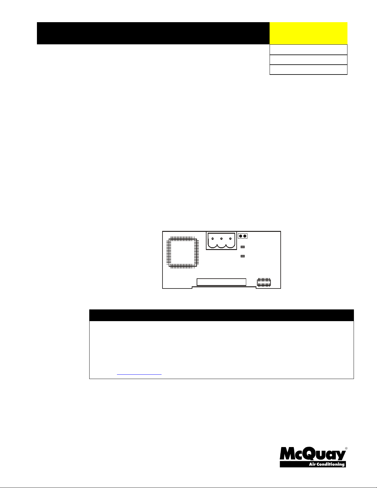
The MicroTech II LonWorks Communications Module is a printed circuit board that plugs into the
MicroTech II Chiller Unit Controller. Figure 1 is an outline drawing of the printed circuit board.
Figure 1. MicroTech II LonWorks Communications Module (Component Side)
4 IM 735-0
Page 5
Application
A MicroTech II LonWorks Communications Module connects the MicroTech II Unit Controller to
the Building Automation System (BAS) on a LonWorks network. It is the interface adapter for the
exchange of LonTalk variables between the network and the unit controller. The MicroTech II
LonWorks Communications Module translates the LonWorks variables of the profile into the native
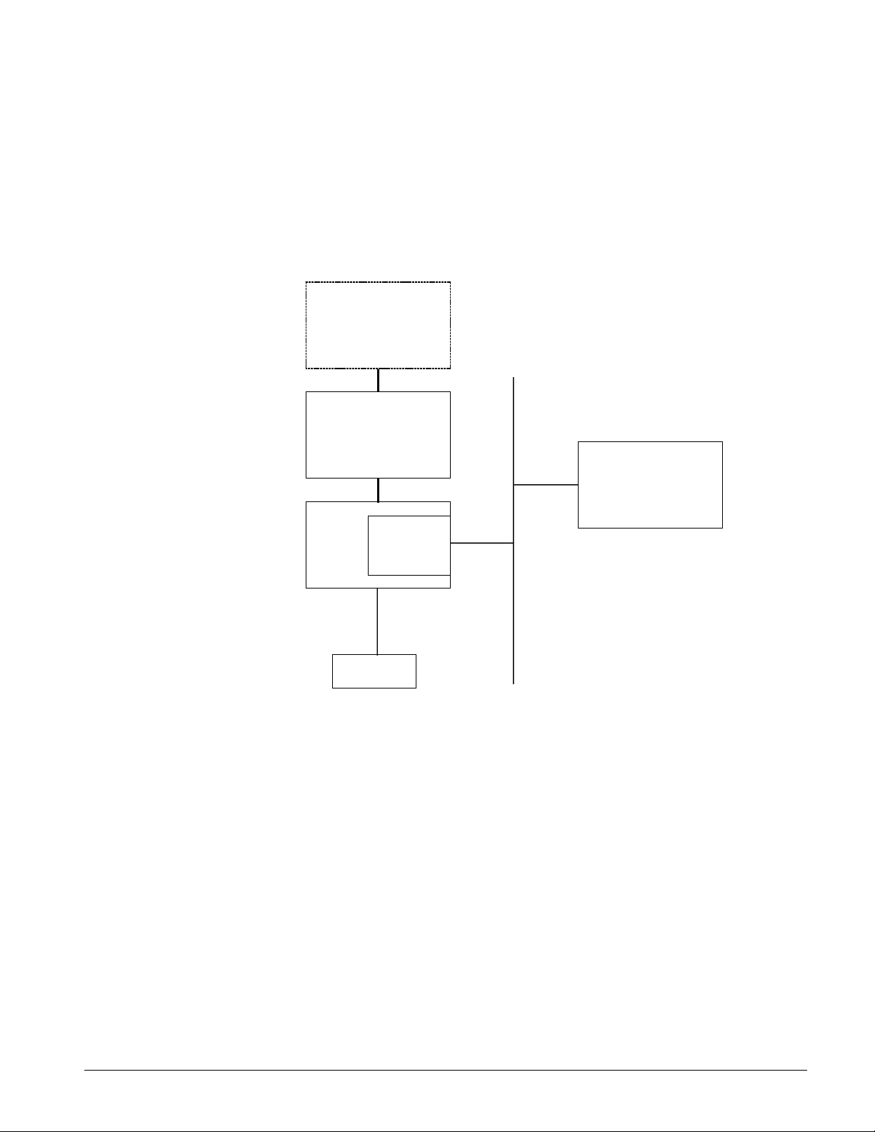
information of the unit controller. Figure 2 shows the MicroTech II LonWorks Communications
Module and Unit Controller integrated into a BAS. Refer to the appropriate Unit Operation manual
for keypad details. See Reference Documents for part numbers.
Figure 2. Building Automation System
Compressor Controller
Optional
LonWorks
FTT-10A
Network
Compressor Controller
System Integration Node
Component Data
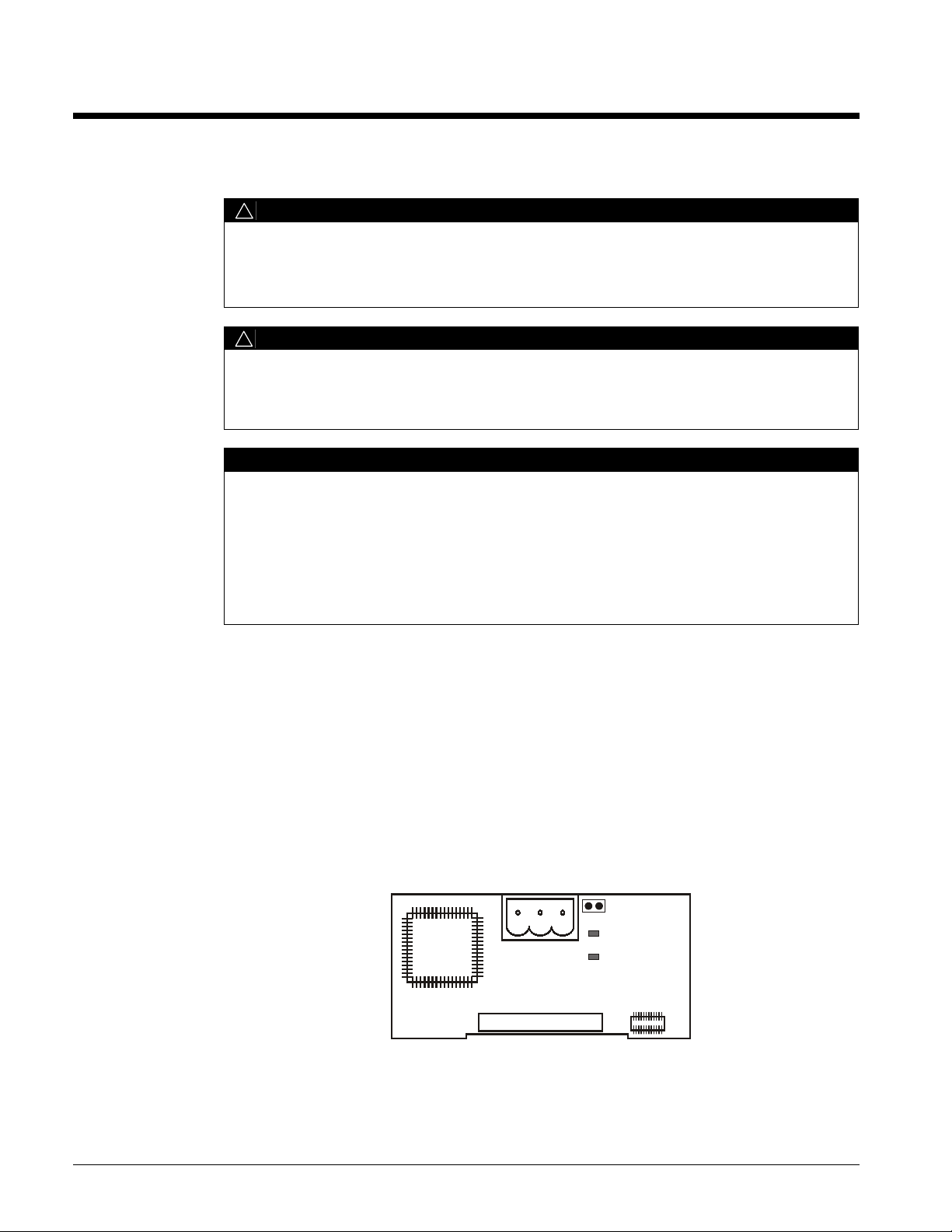
Figure 3 shows the location of the major components of the MicroTech II LonWorks
Communications Module.
MicroTech II
Centrifugal
Chiller Unit
Controller
MicroTech II
MicroTech II
LonWorks
Communications
Module
Keypad
IM 735-0 5
Page 6

Figure 3. MicroTech II LonWorks Communications Module Major Components
r
Service Pin
The service pin generates a service-pin message, which contains the Neuron® ID and the program
code identification of the node. A service-pin message is a network message that is generated by a
node and broadcast on the network. It can be used to commission the LonWorks network.
The service pin consists of two terminals next to the network connector that protrude below the cover
on the serial card port of the unit controller. To activate the service pin, short the two pins together
for an instant with the tip of a screwdriver or similar tool.
Network Connector
Se rvice Pin
Se rvice L ED
Anom aly LED
8-Pin C onnecto
1.14 in
2.36 in
Light Emitting Diodes (LEDs)
The communications module has two LEDs to indicate communication activity and status of the
communication module. These indicators cannot be seen when the module is installed in the
controller.
LED Function
Service
(Green)
Anomaly
(Red)
• Lights when the service-pin is shorted
• Flashes (1 second) during a Wink co mmand
• Flashes (1/2 second) during commissioning
• Blinking when the node is not commissioned
• Flashes (1 second) when the node has no
application program
• Lights when there is a problem with the module
LonWorks Network Connector
The P8 connector connects the MicroTech II LonWorks Communications Module to the LonWorks
FTT-10A bus.
Pin Function
GND No Connection
A FTT-10A
B FTT-10B
8-Pin Header
The 8-pin header connects the unit controller to the communications module.
6 IM 735-0
Page 7

LonMark Profile Software
The MicroTech II LonWorks Communications Module software translates the Standard Network
Variable Types (SNVTs) and Standard Network Configuration Parameter Types (SCPTs) in
accordance with the LonMark profiles used on the LonWorks network into the variables and
parameters used in the MicroTech II Chiller Unit Controller and conversely.
Neuron
The basis of the communications module is an Echelon® Neuron® integrated circuit. Each Neuron
chip contains a globally (i.e., worldwide) unique, 48-bit serial-number called the Neuron ID. The
Neuron ID can be used to address the device on the LonWorks network.
Transceiver
The Echelon Corporation Free Topology Transceiver (FTT-10A) is used to communicate on the
LonWorks network. The network topology may consist of a: star, daisy-chain, or other topology. Data
transmission rate on the network is 78 kbps (baud).
Specifications
Characteristic Description
Network Topology Flexible Free Topology
Neuron Chip Processor 3150
Free Topology Transceiver (FTT-10A) 50051
Cable Types TIA Category 5 (recommended)
Maximum Bus Length 1476 ft (450) meters per segment
Maximum Node Separation 820 ft (250 meters)
Data Transmission Two-wire, half duplex
Data Transmission Rate 78 kbps (baud)
IM 735-0 7
Page 8

Installation
Mounting
Mounting a MicroTech II LonWorks Communications Module
The MicroTech II LonWorks Communications Module can be installed in the field or it can be
installed in the factory. The module mounts on connector pins in the unit controller.
The MicroTech II LonWorks Communications Module is included in a kit (Part number 350147401)
and this manual.
!
CAUTION
Electrostatic discharge hazard.
Can cause equipment damage.
This equipment contains sensitive electronic components that may be damaged by
electrostatic discharge from your hands. Before you handle a communications module, touch
a grounded object, such as the metal enclosure, in order to discharge the electrostatic
potential in your body.
To mount a MicroTech II LonWorks Communications Module
1. Remove power from the unit controller.
2. Locate the Serial Card slot on the unit controller. See Figure 4.
3. Remove the cover from the Serial Card slot if it hasn’t already been removed. Use a small
screwdriver to pry the cover off from one end.
4. Remove the plastic knock-out in the cover.
5. Figure 5 shows a detail of the Serial Card slot showing the 8-pin plug that mates to the receptacle
on the communications module.
6. Grasp the communications module, with the network connector on the underside. The 8-pin
receptacle on the card must mate to the 8-pin plug in the unit controller. The plug has a guide on
each end to direct the card into the mating guide on the receptacle.
Note:
7. Insert the card, pointing up, into the slot, rolling the card into a level position as you move it into
8. Keeping the card level, move the card in the slot until you feel the connectors line up. The correct
9. When you feel the connectors align, press the communications module into the connector. Ensure
10. Replace the cover on the Serial Card slot. Slip the cover over the network connector plug.
11. Route the network cable through the third knockout from the l eft and over to t he communications
12. Connect the MicroTech II LonWorks Communications Module to the network. See Figure 6.
8 IM 735-0
This operation relies more on feeling the card into the connector than seeing the connectors
mate.
the slot.
position seems to be level, toward the left side of the slot, and down slightly from the top.
that the card is firmly seated in the connector.
module.
Figure 7 shows a detail of the network connector plug.
a. Connect one wire of the network cable to Pin A of the connector plug. See Figure 7.
b. Connect the other wire to Pin B of the connector plug. See Figure 7.
c. No wire is connected to the remaining pin.
Page 9

Figure 4. Serial Card Slot Location on Unit Controller
®
Air Conditioning
Figure 5. Serial Card Slot Detail.
J4
VG
VG0Y1Y2Y3Y4
J5
ID1
8-Pin Connector
for LonWorks
Communications
Module
ID2
ID3
ID4
J19
ID15H
ID15
IDC15
ID5
ID6
ID7
IM 735-0 9
Page 10

Figure 6. Network Cable Routing and Connections
Figure 7. Network Connection Detail
Pin A
Pin B
Network Cable
10 IM 735-0
Page 11

Replacing an Existing MicroTech II LonWorks Communications Module
To replace a MicroTech II LonWorks Communications Module
1. Remove power from the Main Control Board.
2. Locate the Serial Card slot on the unit controller. See Figure 4.
3. Pull the network cable connector from the communications module.
4. Remove the cover from the Serial Card slot. Use a small screwdriver to pry it off from one end.
5. Grasp the communications module and carefully pull it from the controller.
6. Install the new communications module:
7. Figure 5 shows a detail of the Serial Card slot showing the 8-pin plug that mates to the receptacle
on the communications module.
8. Grasp the communications module, with the network connector on the underside. The 8-pin
receptacle on the card must mate to the 8-pin plug in the unit controller. The plug has a guide on
each end to direct the card into the mating guide on the receptacle.
Note:
9. Insert the card, pointing up, into the slot, rolling the card into a level position as you move it into
10. Keeping the card level, move the card in the slot until you feel the connectors line up. The correct
11. When you feel the connectors align, press the communications module into the connector. Ensure
12. Replace the cover on the Serial Card slot. Slip the cover over the network connector plug.
13. Insert the network cable connector into the communications module.
This operation relies more on feeling the card into the connector than seeing the connectors
mate.
the slot.
position seems to be level, toward the left side of the slot, and down slightly from the top.
that the card is firmly seated in the connector.
Unit Setup for Network Control
To setup the MicroTech II Unit Controller for network control
1. Disable the chiller. The chiller should not be operating while performing this setup.
2. At the unit controller keypad,
a. In the SET UNIT SPs (1) screen, set the setpoint “Source” equal to “Local.” Use the
Operator Password of “100.”
b. In the SET UNIT SPs (1) screen, set the “Enable” setting equal to “Off.”
c. In the SET UNIT SPs (13 or 14) screen, set the protocol parameter equal to “LonWorks”.
Use the Manager Password of “2001.”
3. Verify with the chiller technician that the chiller is operational.
4. At the unit controller keypad,
a. In the SET UNIT SPs (1) screen, set the setpoint “Source” equal to “BAS”. Use the
Operator Password of “100.”
IM 735-0 11
Page 12

Integration
Ri
Integrating the MicroTech II LonWorks Communications Module into a BAS involves three steps:
!
Connecting the unit (node) to the network,
!
Addressing and establishing communications with the unit, and
!
Configuring the unit to the building.
Connecting to the Network
After you have installed the MicroTech II LonWorks Communications Module in the unit, you must
connect it into the LonWorks network.
Network Topology
Each MicroTech II LonWorks Communications Module is equipped with an FTT-10A transceiver for
network communications. This transceiver allows for (1) free topology network wiring schemes using
twisted pair (unshielded) cable and (2) polarity insensitive connections at each node. These features
greatly simplify installation and reduce network commissioning problems. Additional nodes may be
added with little regard to existing cable routing.
Free Topology Networks
A LonWorks “free topology network” means that devices (nodes) can be connected to the network in
a variety of geometric configurations. For example, devices can be daisy-chained from one device to
the next, connected with stub cables branching off from a main cable, connected using a tree or star
topology, or any of these configurations can be mixed on the same network.
Free topology segments require termination for proper transmission performance. Only one
termination is required. It may be placed anywhere along the segment
FTT-10A Transceiver User’s Guide for details.
Free topology networks may take on the following topologies:
• Bus
• Ring
• Star
• Mixed - Any combination of Bus, Ring, and Star
As shown in Figure 8.
. Refer to Echelon LonWorks
See Reference Documents for part number.
Note:
Limitations to wire lengths apply and must be observed.
Figure 8. Singly Terminated Free Topology Networks
ng Topology
Singly Terminated Bus Topology
Termination
Termination
12 IM 735-0
Termination
Mixed Topology
Stub
}
Star Topology
Termination
Page 13

A network segment is any part of the free topology network in which each conductor is electrically
continuous. Each of the four diagrams is an illustration of a network segment. Some applications may
require two or more segments; see “Free Topology Restrictions.”. If necessary, segments can be
joined with FTT-10A-to-FTT-10A physical layer repeaters. See Figure 9.
LonWorks FTT-10A Transceiver User’s Guide for details.
See Reference Documents for part
Refer to Echelon
number.
Figure 9. Combining Network Segments With a Repeater
Termination Termi natio n
FTT-10A
FTT-10A
Free Topology Restrictions
Although free topology wiring is very flexible, there are restrictions. A summary follows, refer to the
Echelon FTT-10A User’ s Guide for details
1. The maximum number of nodes per segment is 64.
2. The maximum total bus length depends on the wire size (see “Qualified Cables” for details):
Wire Size Maximum Node-to-Node Length Maximum Cable Length
24 AWG 820 ft (250 m) 1476 ft (450 m)
22 AWG 1312 ft (400 m) 1640 ft (500 m)
16 AWG 1640 ft (500 m) 1640 ft (500 m)
The longest cable path between any possible pair of nodes on a segment must not exceed the
maximum node-to-node distance. If two or more paths exist between a pair of nodes (e.g., a loop
topology), the longest path should be considered. Note that in a bus topology, the longest nodeto-node distance is equal to the total cable length.
Note:
The total length of all cable in a segment must not exceed the maximum total cable length.
3. One termination is required in each segment. It may be located anywhere along the segment.
. See Reference Documents for part number.
Doubly Terminated Networks
You can extend the maximum total cable length without using a repeater by using doubly-terminated
network topology. See Figure 10. The trade-offs are (1) this network topology must be rigorously
followed during the installation and subsequent retrofits and (2) two terminations must be installed at
the ends of the bus for proper transmission performance.
Transceiver User’s Guide for details.
Note:
Limitations to wire lengths apply and must be observed.
See Reference Documents for part number.
Refer to Echelon LonWo r ks FTT-10A
Figure 10. Doubly Terminated Network Topology
Termination Termination
Doubly Terminated Topology Restrictions
The restrictions on doubly-terminated bus topology are as follows:
IM 735-0 13
Page 14

1. The maximum number of nodes per segment is 64.
2. The maximum total bus length depends on the wire size (see “Qualified Cables” for details):
Wire Size Maximum Cable Length
24 AWG 2952 ft (900 m)
22 AWG 4590 ft (1400 m)
16 AWG 8855 ft (2700 m)
3. The maximum stub length is 9. 8 ft (3 m).
A stub is a piece of cable that is wired between the node and the bus. Note that if the bus is wired
directly to the node, there is no stub, and thus the stub length is zero. If you are wiring to a field
terminal strip on a unit, be sure to account for any factory wiring between the terminal strip and
the controller. This wiring is considered part of the stub.
4. Two terminations are required in each segment. One must be located at each end of the bus.
Physical Network
Qualified Cables
Echelon has qualified three twisted-pair network communications cables that are available from a
large number of different sources.
Transceiver Users Guide for details.
or applications may require the use of plenum-rated cable. The following cables meet this
specification.
1. TIA568A Category 5 cable (24AWG/0.51mm)
2. NEMA Level IV cable (22AWG/0.65mm)
3. Generic 16AWG (1.3mm) (similar to Belden 85102)
Do not install the cable in the same conduit with power wiring. The temperature of the cable must not
exceed 131°F (55°C).
Refer to Echelon LonWorks FTT-10A Free Topology
See Reference Documents for part number. Some local codes
Note:
Ideally, you should connect two controllers with one continuous piece of cable in order
to reduce the risk of communications errors. If you must splice the cable, use crimp-type
butt connectors (good) or solder (best). Do not use wire nuts.
Network Cable Termination
LonWorks network segments require termination for proper data transmission performance. The type
and number of terminations depend on network topology.
Transceiver User’s Guide for details
. See Reference Documents for part number.
Refer to Echelon LonWo r ks FTT-10A
14 IM 735-0
Page 15

Addressing and Establishing Communications
LonWorks Network Addressing
Every Neuron Chip has a unique 48-bit Neuron ID or physical address. This address is generally used
only at initial installation or for diagnostic purposes. For normal network operation, a device address
is used.
Device addresses are defined at the time of network configuration. All device addresses have three
parts. The first part is the Domain ID, designating the domain. Devices must be in the same domain in
order to communicate with each other. The second part is the Subnet ID that specifies a collection of
up to 127 devices that are on a single channel or a set of channels connected by repeaters. There may
be up to 255 subnets in a domain. The third part is the Node ID that identifies an individual device
within the subnet.
A group is a logical collection of devices within a domain. Groups are assembled with regard for their
physical location in the domain. There may be up to 256 groups in a domain. A group address is the
address that identifies all devices of the group. There may be any number of devices in a group when
unacknowledged messaging is used. Groups are limited to 64 de vices if acknowledged messaging is
used.
A broadcast address identifies all devices within a subnet or domain.
Commissioning the Network
Pressing the service pin generates a service-pin message, which contains the Neuron ID and the
program code identification of the node. A service-pin message is a network message that is
generated by a node and broadcast on the network. It can be used to commission the LonWorks
network.
A network configuration tool maps device Neuron IDs to the domain/subnet/node logical addressing
scheme when it creates the network image, the logical network addresses and connection information
for all devices (nodes) on the network.
External Interface File (XIF)
LonMark guidelines specify exact documentation rules so that proprietary configuration tools are not
required to commission and configure LonWorks devices. The MicroTech II LonWorks Chiller
Communications Module is self-documenting so that any network management tool can ob t ain all the
information needed over the network to connect it into the system and to configure and manage it. An
external interface file (a specially formatted PC text file with the extension .XIF) is also available so
that any network tool can design and configure it prior to installation. For a copy of the XIF file,
contact your local McQuay International representative.
Configuring the Unit Controller
The MicroTech II Chiller Controller LonWorks Communications Module is configured at the factory
as a chiller unit controller in accordance with the LonMark Chiller functional profile. The unit is
ready to operate with the default values of the various parameters set at the factory. Default values
may be changed via the network. See the appropriate operation manual for default values and keypad
operation and see the MicroTech II Chiller Protocol Information for descriptions of the network
variables. See Reference Documents for part numbers.
IM 735-0 15
Page 16

Service Information
Test Procedures
If you can control the unit from its keypad, but you are unable to communicate with it via the
network:
• Check the network wiring
• Check that the Control Source setpoint is set to Local. See Unit Setup for Network Control on
page 11.
• Check that the Protocol setpoint is set to LonWorks. See Unit Setup for Network Control on page
11.
• Check addressing
!
Activate the Service Pin on the communications module to send the service message to the
network.
!
The service-pin message contains the Neuron ID and the program code identification of the
node.
If the MicroTech II Chiller LonWorks Communications Module still does not respond, replace the
communications module.
Replaceable Parts List
Network Connection Plug
Generic Replacement Parts
If you lose this terminal block you can replace it with a standard block from a manufacturer. The list
below contains manufact urers part numbers for equivalent parts.
Manufacturer Telephone Order Number
Phoenix Contact (800) 888-7388 17 57 02 2
Altech Corp (908) 806-9400 37.003
Replacement Kit
Component Description Part No.
Kit, Chiller Installation Kit for LonMark Communications Module 350147401
13600 Industrial Park Boulevard, Minneapol i s, MN 55441 USA (800) 432-1342, www.mcquay.com
 Loading...