

Page 1

Installation & Maintenance Data IM 439-15
Large Vertical Water Source Heat Pumps
6 thru 25 Tons
Models LDD, LDE, LDL, LDS, LME, LMH, LML, LMS
Group: WSHP
Part Number: 106581103
Date: June 2006
©2006 McQuay International
®
Page 2

Contents
Model Nomenclature .................................................... 2
Transportation and Storage ......................................... 2
Installation.................................................................. 3-6
Piping ............................................................................ 7
Cleaning and Flushing System ..................................... 8
Start-up ...................................................................... 8-9
Operating Limits ........................................................... 9
Electrical Data ............................................................... 9
Typical Wiring Diagrams ........................................ 10-13
Model Nomenclature
W LDD 1 070 D Z
Product Category
W = WSHP
Product Identifier
See box below
Typical Mark IV/AC units ................................. 10-11
Typical MicroTech units .................................. 12-13
Unit Operation ............................................................ 14
Mark IV Sequence of Operation ................................. 15
Thermostat Connections............................................ 16
Miscellaneous Options on Mark IV Units .............. 17-20
Field Installed Options on MicroTech Units ................ 21
Troubleshooting WSHP .............................................. 22
Maintenance ............................................................... 23
Design Series
1 = A Design
2 = B Deisgn
3 = C Design
4 = D Design
5 = E Design
Nominal Capacity
070 = 70,000
108 = 108,000
121 = 121,000
Coil Options
(None)
Voltage
D= 208-60-3
H= 230-60-3
K= 460-60-3
L= 575-60-3
N= 380-50-3
180 = 180,000
215 = 215,000
290 = 290,000
etc. . .
McQuay Product Identifiers
LDD = Std. Large Vertical/DDC Controls/Std. Range/Less Board LME = Std. Large Verical/Mark IV/Ext. Range
LDE = Std. Large Vertical/DDC Controls/Ext. Range LMH = High Static Large Vertical/Mark IV/Std. Range
LDL = Std. Large Vertical/DDC Controls/Ext. Range/Less Board LML = High Static Large Vertical/Mark IV/Ext. Range
LDS = Std. Large Vertical/DDC Controls/Std. Range LMS = Std. Large Vertical/Mark IV/Std. Range
Page 2 of 24 / IM 439
Page 3

Note: Installation and maintenance are to be performed only
by qualified personnel who are familiar with local
codes and regulations, and are experienced with this
type of equipment.
CAUTION
!
Sharp edges are a potential injury hazard. Avoid contact with
them.
Transportation and Storage
Upon receipt of the equipment, check unit for visible damage. Make a notation on the shipper’s delivery ticket before
signing. If there is any evidence of rough handling, the
cartons should be opened at once to check for concealed
damage. If any damage is found, notify the carrier within 48
hours to establish your claim and request their inspection
and a report. The Warranty Claims Department should then
be contacted.
Do not stand or transport the machines on end. For storing,
each unit must be in the “up” position.
In the event that elevator transfer makes upended positioning unavoidable, absolutely ensure that the machine is in the
normal upright position for at least 24 hours before operating.
Temporary storage at the jobsite must be indoors, completely sheltered from rain, snow, etc. High or low temperatures naturally associated with weather patterns will not
harm the conditioners. Excessively high temperatures 140°F
(60°C) may deteriorate certain plastic materials and cause
permanent damage. In addition, the solid-state circuit boards
may experience operational problems.
Installation
General
1. To prevent damage, this equipment should not be oper-
ated for supplementary heating and cooling during the
construction period.
2. Inspect the shipping label for any specific tagging numbers
indicated per request from the installing contractor. At this
time the voltage, phase and capacity should be checked
against the plans.
3. Check the unit size against the plans to be sure that the unit
will be installed in the correct location.
4. After removing the packaging material, remove unit from
the skid.
5. Before installation, check the available dimensions versus
the dimensions of the unit.
6. Pay attention to the location and routing of water piping,
condensate drain piping, and electrical wiring. The loca-
tions of these items are clearly marked on submittal
drawings.
7. The installing contractor will find it beneficial to confer with
piping, sheetmetal, ceiling and electrical foremen together
before installing any conditioners.
Note: Check the unit name plate for correct voltage with the
plans before installing the equipment. Also, make sure
all electrical ground connections are made in accordance with local code.
8. We recommend that the contractor cover the conditioners
with plastic film to protect the machines during finishing of
the building. This is important if spraying fireproofing
material on bar joists, sandblasting, spray painting and
plastering operations have not been completed.
Unit Location
1. Locate the unit in an area that allows for easy removal of
the filter and access panels, and has enough space for
service personnel to perform maintenance or repair. Provide sufficient room to make water, electrical and duct connections
(see Figure 1 for service clearance details)
.
2. The contractor should make sure that access has been
provided including clearance for 2" (51 mm) thick filter brackets, duct collars and fittings at water and electrical connections.
3. Allow adequate room around the unit for a condensate trap.
4. The unit can be installed “free standing” in an equipment
room. Generally, the unit is located in a separate room with
the non-ducted return air facing the return air intake. Alternatively, the unit can have a ducted return air.
5. It is recommended that the unit be located on vibration isolators to reduce any vibration
(see Figure 3)
.
6. If optional field installed controls are required (Boilerless
System), space must be provided for the enclosure to mount
on the side of the unit.
Figure 1. Service clearance
Side B
Fan Motor
Side A
24" (610 mm)
Control Box
Location
24"
(610 mm)
Piping
Location
IMPORTANT
1. A 24" (610 mm) minimum clearance is required on the
return air, control box and piping sides. However, a 36"
(914 mm) clearance allows for easier serviceability.
2. A 12" (305 mm) minimum clearance is required on Side
A to gain access to panel to remove locking collar for shaft
removal.
3. A 6" (152 mm) clearance is required on Side B to remove
screws holding top panel.
4. Top clearance is required for fan shaft removal.
5. Some codes dictate a 60" (1524 mm) clearance above
the control box which could be violated with a ducted
return. Check your codes.
IM 439 / Page 3 of 24
Page 4

Unit Arrangement
Two fan discharges and piping arrangements are available.
With the return air side defined as the “front” of the unit, the
water piping and electrical power connections may be righthand (side) or left-hand. The main control panel is located in
the center of the unit, lower section under the return air filter.
Unit sides opposite the control panel and opposite the piping
side may be up against walls and still allow for service and
maintenance through the remaining access panels.
Filter Access
Each unit is shipped with a filter bracket for side filter
removal.
Figure 2. Side view from piping end
M
M
Piping
Control Box Location
Piping
Fan Motor
Vibration Isolation
For minimum sound and vibration transmission, it is recommended that the unit be mounted on vibration isolators.
Holes are provided in the bottom panel to facilitate con-
nection of isolators
(see Figure 3 for hole locations)
Isolators supplied by the manufacturer are the type shown
in Figures 4 and 5. Four white isolators are used for single
compressor units and six green isolators are used for dual
compressor units. The holes in the bottom of the unit allow for
3
⁄8" (10 mm) bolt to be secured to the isolator.
a
Figure 4. Single compressor unit — vibration isolators
3" (76 mm)
7
(4)
5
/32"
28
(715 mm)
3" (76 mm)
3" (76 mm)
23
54
/32"
(1390 mm)
.
/16" (11 mm) holes
Figure 3. Isolator
25/8" (61 mm)
7
/16" (11 mm) dia.
AA
3" (76 mm)
1
/
4
2"
(51 mm)
Section A-A
3
" (114 mm)
2
1
" (140 mm)
2
/
5
7
/16" (11 mm)
/8" (10 mm) TAP
21/2" (64 mm)
1
/4" (6 mm)
Figure 5. Dual compressor unit — vibration isolators
2" (51 mm)
1
/8"
30
(765 mm)
2" (51 mm)
1
3
/4" (83 mm)
Page 4 of 24 / IM 439
3
80
/8"
(2042 mm)
(6) 3/8" (10 mm) holes
3
/16"
40
(1021 mm)
1
/4" (83 mm)
3
Page 5
Air Balancing
All units are supplied with a variable pitch motor sheave to aid
in airflow adjustment. They are typically set at the low end of
the rpm range for field adjustment to the required airflow.
When the final adjustments are complete, the current
draw of the motors should be checked and compared to the
full load current rating of the motors. The amperage must not
exceed the service factor stamped on the motor nameplate.
Upon completion of the air balance, it is a common
industry recommendation that the variable pitched motor
sheave be replaced with a properly sized fixed sheave. A
matching fixed sheave will provide longer belt and bearing
life and vibration free operation. Initially, it is best to have a
variable pitched motor sheave for the purpose of air balancing,
but once the balance has been achieved, fixed sheaves
maintain balancing and alignment more effectively.
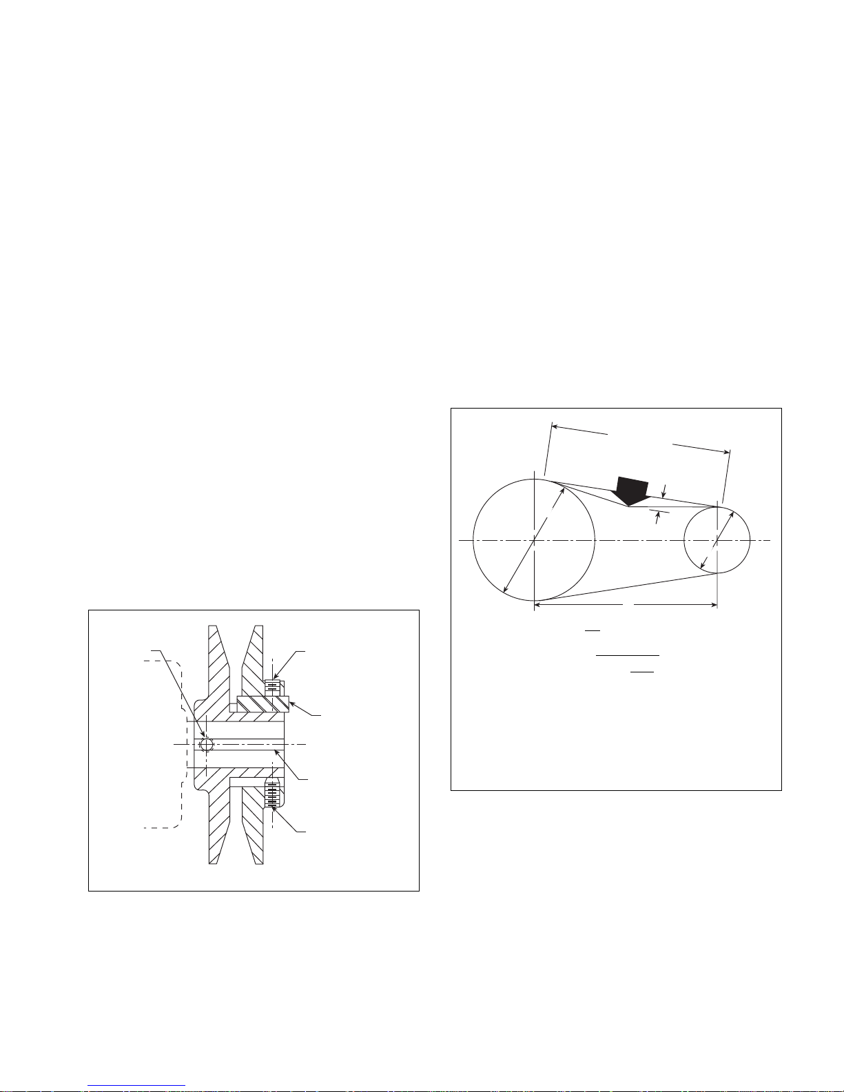
Adjustment (See Figure 6)
1. All sheaves should be mounted on the motor or driving
shaft with the setscrew “A” toward the motor.
2. Be sure both driving and driven sheaves are in alignment
and that shafts are parallel.
3. Fit internal key “D” between sheave and shaft, and lock
setscrew “A” securely in place.
4. Put on belts and adjust belt tension to 4 lbs. ± 0.7 lbs.
(18 ± 3N) for a
1
⁄2" to 3⁄4" (13 mm to 19 mm) belt deflection
height.
5. To determine the deflection distance from normal position,
use a straightedge or stretch a cord from sheave to sheave
to use as a reference line. On multiple-belt drives an adjacent
undeflected belt can be used as a reference.
6. Future adjustments should be made by loosening the belt
tension and increasing or decreasing the pitch diameter
of the sheave by half or full turns as required. Readjust belt
tension before starting drive.
7. Be sure that all keys are in place and that all setscrews are
tight before starting drive. Check setscrews and belt tensio n
after 24 hours service.
8. When new V-belts are installed on a drive, the initial
tension will drop rapidly during the first few hours. Check
tension frequently during the first 24 hours of operation.
Subsequent retensioning should fall between the minimum and maximum force.
Figure 7. Drive belt adjustment
Adjusting:
1. Loosen setscrews “B” and “C” in moving parts of sheave
and pull out external key “E”. (This key projects a small
amount to provide a grip for removing.)
2. Adjust sheave pitch diameter for desired speed by opening moving parts by half or full turns from closed position.
Do not open more than five full turns.
3. Replace external key “E” and securely tighten setscrews
“B” over key and setscrews “C” into keyway in fixed half of
the sheave.
Figure 6.
“A”
“B”
“E”
“D”
Span Length (t)
Deflection
Force
D
h
d
C
t
h=
64
t= C2 –
√
Where:
t= Span length, inches (mm)
C= Center distance, inches (mm)
D= Larger sheave diameter, inches (mm)
d= Smaller sheave diameter, inches (mm)
h= Deflection height, inches (mm)
Note: The ratio of deflection to belt span is 1:64.
D-d
()
2
Single Groove
“C”
Key “E” projects to
provide a grip for
removing.
IM 439 / Page 5 of 24
Page 6

Ductwork and Attenuation
Discharge ductwork is normally used with these conditioners.
Return air ductwork may also be required but will require field
installation of a return air duct collar.
All ductwork should conform to industry standards of good
practice as described in ASHRAE Systems Guide.
The discharge duct system will normally consist of a flexible connector at the unit, a transition piece to the final duct
size, a short run of duct, an elbow without vanes and a trunk
duct tee’d into branch ducts with discharge diffusers as shown
in Figure 10. Transition piece must not have angles totalling
more than 30 degrees or severe loss of air performance can
result.
All units have multiple fan outlets. A single duct can enclose all the openings as shown in Figure 10; however, the
preferred method for minimum static pressure loss would be
individual ducts at each outlet connected to a larger duct downstream.
For minimum noise transmission, the metal duct material
should be internally lined with acoustic fibrous insulation.
The ductwork should be laid out so that there is no line of
sight between the conditioner discharge and the distribution
diffusers.
Return air ducts can be brought in adjacent to the return
air of the conditioner. T ypically, the equipment room becomes
the common return air plenum.
Do not insert sheetmetal screws directly into the unit cabinet for connection of supply or return air ductwork, especially
return air ductwork which can hit the drain pan or the air coil.
Ventilation Air
Outside air may be required for ventilation. The temperature
of the ventilation air must be controlled so that mixture of outside air and return air entering the conditioner does not exceed conditioner application limits. It is also general practice
to close off the ventilation air system during unoccupied periods (night setback).
The ventilation air system is generally a separate building subsystem with distribution ductwork. Simple introduction
of the outside air into each return air plenum chamber reasonably close to the conditioner air inlet is not only adequate,
but recommended. Do not duct outside air directly to the conditioner inlet. Provide sufficient distance for thorough mixing
of outside and return air
(see Operating Limits on page 9).
Optional Duct Collar and 2" (51 mm)
Filter Rack
The optional duct collar kit is used to facilitate connection of
return air duct to the unit. The duct collar kit can be used in
conjunction with the standard 1" (25 mm) thick filter rack or
the optional 2" (51 mm) filter rack.
The 2" (51 mm) filter rack facilitates the installation of 2"
(51 mm) thick filters for side removal. The 2" (51 mm) filter
rack replaces the existing 1" (25 mm) filter rack and does not
require the use of the optional return air duct collar.
The kits are installed as follows:
1. Remove all filters, filter racks and brackets. Save all
screws. Discard bracket end.
2. Attach top duct collar in conjunction with top filter rack
with truss head screws.
3. Attach bottom duct collar and filter rack.
4. On single compressor units, attach two flanges using four
(4) #8 truss head screws provided.
5. Attach center support in original location.
6. Locate and attach center filter racks using screws pro-
vided.
7. Attach duct collar sides using eight (8) #10 sheetmetal
8. No point in the drain system may be above the drain
connection of any unit.
9. Automatic flow controlled devices must not be installed
prior to system cleaning and flushing.
10. A high point of the piping system must be vented.
11. Check local code for the need of dielectric fittings.
Figure 8. Assembly detail
Filter
Rack
Duct
Collar
Duct Collar Side
Figure 9.
Center Support
Chassis
Page 6 of 24 / IM 439
Side Flanges
Door End
Top Duct Collar
Duct Collar Side
Top Filter Rack
Center Filter Racks
Filters
Page 7
Piping
CAUTION
!
Do not overtorque fittings. The maximum torque without
damage to fittings is 30 foot pounds. If a torque wrench is not
available, use as a rule of thumb, finger-tight plus one
quarter turn. Use two wrenches to tighten the union, one to
hold the line and one for simultaneous tightening of the nut.
1. All units are recommended to be connected to supply and
return piping in a two-pipe reverse return configuration. A
reverse return system is inherently self-balancing and requires only trim balancing where multiple quantities of units
with different flow and pressure drop characteristics are
connected to the same loop. A simple way to check for
proper water balance is to take a differential temperature
reading across the water connections. To insure proper
water flow, the dif ferential should be 10°F to 14°F (5°C to
8°C) in the cooling mode of operation.
A direct return system may also be made to work acceptably , but proper water flow balancing is more difficult
to achieve and maintain, and may require flow control
devices.
2. The piping can be steel, copper or PVC.
3. Supply and return runouts are usually connected to the
unit by short lengths of high pressure flexible hose which
are sound attenuators for both unit operating noise and
hydraulic pumping noise. One end of the hose should have
a swivel fitting to facilitate removal for service. Hard piping can also be brought directly to the unit although it is
not recommended since no vibration or noise attenuation
can be accomplished. The hard piping must have unions
to facilitate unit removal
setup)
.
(see Figure 10 for typical piping
Figure 10.
Branch
Duct
Trunk Duct
4. Supply and return shutoff valves are required at each conditioner. The return valve is used for balancing and should
have a “memory stop” so that it can always be closed off
but can only be reopened to the proper position for the flow
required.
5. No unit should be connected to the supply and return piping until the water system has been cleaned and flushed
completely. After the cleaning and flushing has taken place,
the initial connection should have all valves wide open in
preparation for water system balancing.
6. Condensate piping can be steel, copper or PVC. Each
unit is supplied with a FPT threaded fitting.
7. The condensate disposal piping must have a trap and the
piping must be pitched away from the unit not less than
1
⁄4" per foot (21 mm per meter). Generally , the condensate
trap is made of copper. A complete copper or PVC condensate system can also be used. Union fittings in the copper
lines should be applied to facilitate removal.
8. No point in the drain system may be above the drain connection of any unit.
9. Automatic flow controlled devices must not be installed
prior to system cleaning and flushing.
10. A high point of the piping system must be vented.
11. Check local code for the need of dielectric fittings.
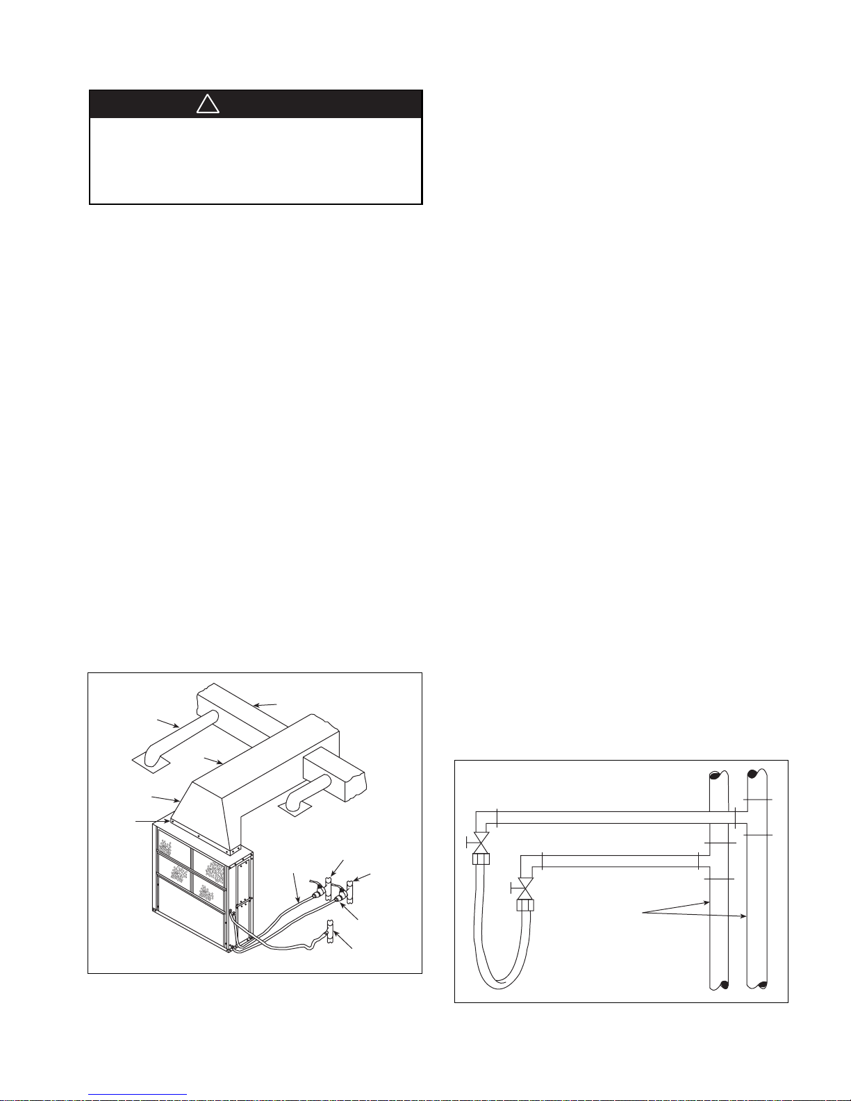
Cleaning and Flushing
System
1. Prior to first operation of any conditioner, the water cir-
culating system must be cleaned and flushed of all construction dirt and debris.
If the conditioners are equipped with water shutoff
valves, either electric or pressure operated, the supply and
return runouts must be connected together at each conditioner location. This will prevent the introduction of dirt
into the unit. Additionally, pressure operated valves only
open when the compressor is operating
(see Figure 1 1)
.
Main
Duct
Transition
Duct
Flexible
Connector
Flexible Hose
with Brass
Pipe Fittings
Supply
Return
Balancing
Valve with
Close-off
Condensate
Figure 11.
Return Runout
Supply Runout
Rubber Hose
Runouts Initially
Connected Together
Mains
IM 439 / Page 7 of 24
Page 8

Cleaning and Flushing System (Continued)
2. The system should be filled at the city water makeup
connection with all air vents open. After filling, vents should
be closed.
The contractor should start main circulator with pressure reducing valve makeup open. Vents should be
checked in sequence to bleed off any trapped air to assure circulation through all components of the system.
Power to the heat rejector unit should be off, and the
supplementary heat control set at 80°F (27°C).
While circulating water, the contractor should check
and repair any leaks in the piping. Drain at the lowest
point(s) in the system should be opened for initial flush
and blowdown, making sure city water fill valves are set
to make up water at the same rate. Check the pressure
gauge at pump suction and manually adjust the makeup
to hold the same positive steady pressure both before
and after opening the drain valves. Flush should continue for at least two hours, or longer if required, to see
clear, clean drain water.
3. Supplemental heater and circulator pump should be shut
off. All drains and vents should be opened to completely
drain down the system. Short circuited supply and return runouts should now be connected to the conditioner
supply and return connections. Teflon tape is recommended over pipe dope for pipe thread connections. Use
no sealers at the swivel flare connections of hoses.
4. Trisodium phosphate was formerly recommended as a
cleaning agent during flushing. However, many states
and localities ban the introduction of phosphates into their
sewage systems. The current recommendation is to simply flush longer with warm 80°F (27°C) water.
5. Refill the system with clean water. Test the litmus paper
for acidity, and treat as required to leave the water slightly
alkaline (pH 7.5 to 8.5). The specified percentage of antifreeze may also be added at this time. Use commercial
grade anti-freeze designed for HVAC systems only. Do
not use automotive grade anti-freeze.
6. Set the system control and alarm panel heat add setpoint
to 70°F (21°C) and the heat rejection setpoint to 85°F
(29°C). Supply power to all motors and start the circulating pumps. After full flow has been established through
all components including the heat rejector (regardless of
season) and air vented and loop temperatures stabilized,
each of the conditioners will be ready for check, test and
start-up and for air and water balancing.
Start-up
1. Open all valves to full open position and turn on power to
the conditioner.
2. Set thermostat for Fan Only operation by selecting Off at
the system and On at the fan switch. If Auto fan operation
were selected, the fan would cycle with the compressor.
Check for proper air delivery.
3. All units have variable pitch motor sheaves. Reset for
correct airflow.
4. Set thermostat to Cool. If the thermostat is an automatic
changeover type, simply set the cooling temperature to
the coolest position. On manual changeover types additionally select Cool at the system switch.
Again, many conditioners have time delays which
protect the compressor against short cycling. After a few
minutes of operation, check the discharge grilles for cool
air delivery. Measure the temperature difference between
entering and leaving water. It should be approximately
1
1
⁄2 times greater than the heating mode temperature
difference. For example, if the cooling temperature difference is 15°F (8°C), the heating temperature difference
should have been 10°F (5°C).
Without automatic flow control valves, a cooling temperature difference of 10°F to 14°F (5°C to 8°C) is about
right. Adjust the combination shutoff/balancing valve in
the return line to a water flow rate which will result in the
10°F to 14°F (5°C to 8°C) degree difference in cooling.
5. Set thermostat to Heat. If thermostat is the automatic
changeover type, set system switch to the Auto position
and depress the heat setting to the warmest selection.
Some conditioners have built-in time delays which prevent the compressor from immediately starting. With
most control schemes, the fan will start immediately.
After a few minutes of compressor operation, check for
warm air delivery at discharge grille. If this is a “cold
building” start-up, leave unit running until return air to the
unit is at least 65°F (18°C).
Measure the temperature difference between entering and leaving air and entering and leaving water. With
entering water of 60°F to 80°F (16°C to 27°C), leaving
water should be 6°F to 12°F (3.3°C to 6.6°C) cooler, and
the air temperature rise through the machine should not
exceed 35°F (19°C). If the air temperature exceeds 35°F
(19°C), the airflow rate is probably inadequate.
If the water temperature difference is less than 6°F
(3.3°C) degrees, the water flow rate is excessive. If the
water temperature difference exceeds 12°F (6.6°C), then
the water flow rate is inadequate.
6. Check the elevation and cleanliness of the condensate
line. If the air is too dry for sufficient dehumidification,
slowly pour enough water into the condensate pan to
ensure proper drainage.
7. If the conditioner does not operate, the following points
should be checked:
a. Is proper voltage being supplied to the machine?
b. Is the proper type of thermostat being used?
c. Is the wiring to the thermostat correct?
8. If the conditioner operates but stops after a brief period,
check for:
a. Is there proper airflow? Check for dirty filter, incorrect
fan rotation (3-phase fan motors only), or incorrect
ductwork.
b. Is there proper water flow rate within temperature limits?
Check water balancing; backflush unit if dirt-clogged.
9. Check the unit for vibrating refrigerant piping, fan wheels,
etc.
10. Do not lubricate the fan motor during the first year of
operation as it is prelubricated at the factory.
Page 8 of 24 / IM 439
Page 9

Operating Limits
CAUTION
!
Electrical Data
Environment
This equipment is designed for indoor installation only. Sheltered locations such as attics, garages, etc., generally will
not provide sufficient protection against extremes in temperature and/or humidity, and equipment performance, reliability, and service life may be adversely affected.
Table 1. Air and water limits
All UNITS
Cooling Heating
Min. Ambient Air 40°F/5°C40°F/5°C
Normal Ambient Air 80°F/27°C70°F/21°C
Max. Ambient Air 100°F/38°C85°F/29°C
Min. Ent. Air
Normal Ent. Air, 80/67°F70°F
Max. Ent. Air, 100/83°F80°F
➀➁
db/wb 27/19°C21°C
➀➁
db/wb
50°F/10°C40°F/5°C
38/28°C27°C
Table 2. Water enthalpy
Min. Ent. Air
Normal Ent. Air 85°F/29°C70°F/21°C85°F/29°C70°F/21°C
Max. Ent. Air
➀ At ARI flow rate.
➁ Maximum and minimum values may not be combined. If one value is at
maximum or minimum, the other two conditions may not exceed the normal
condition for standard units. Extended range units may combine any two
maximum or minimum conditions, but not more than two, with all other
conditions being normal conditions.
➀➁
➀➁
Cooling Heating Cooling Heating
55°F/13°C55°F/13°C40°F/5°C40°F/5°C
110°F/43°C90°F/32°C 110°F/43°C90°F/32°C
Additional Information
1. All units
Unit will start up in an ambient of 40°F (5°C), with entering
air at 40°F (5°C), with entering water at 40°F (5°C), with
both air and water at flow rates used in the ARI Standard
320-86 rating test, for initial start-up in winter.
General
1. Be sure the available power is the same voltage and phase
as that shown on the unit serial plate. Line and low voltage
wiring must be done in accordance with local codes or the
National Electrical Code, whichever is applicable.
2. Apply correct line voltage to the unit. Each unit is supplied
with a 3-lug terminal block in the main control for threephase main power. Multiple knockouts on the sides of the
unit facilitate conduit connections on the unit for line and
low voltage. A disconnect switch near the unit is required
by code. Power to the unit must be sized correctly and be
fused with Class RK5 dual element fuses.
Minimum and Maximum Voltage
Nameplate 208/60/3: Min. 187 volts, Max. 229 volts
Nameplate 230/60/3: Min. 207 volts, Max. 253 volts
Nameplate 460/60/3: Min. 414 volts, Max. 506 volts
Nameplate 575/60/3: Min. 515 volts, Max. 632 volts
Nameplate 380/50/3: Min. 360 volts, Max. 418 volts
Three-phase system unbalance should not exceed 2%.
Voltages listed are to show voltage range. However, units
operating with overvoltage and undervoltage for extended
periods of time will experience premature component failure.
Note: This is not a normal or continuous operating
condition. It is assumed that such a start-up is for the
purpose of bringing the building space up to
occupancy temperature.
IM 439 / Page 9 of 24
Page 10

L3 L2
32
36
34
35
1
L1
Junction
Box
Term
Board
Comp
19
3
BK
YE
YE
RD
RD
BK
BK
L1
L2
L3
GND
RD
YE
2
18
Crankcase
Heater
30
24
23
22
17
YE
BK
16
YE
BK
21
15
Fan
Motor
GN
GND
YE
RD
BK
Common
Comp
Fan
Mark IV/AC
Board
Compressor
Contactor
36
35
21
L1
37
37
Breaker
(Optional)
OR 230V
RD 208V
BK/RD 460V
BK
BK
YE
GND
Xformer
REV Valve Solenoid
COF
LT
LT
HP
HP
14
46
43
42
BR
BR
BL
High
Press
Switch
Low
Press
Switch
Low
Temp
Switch
Ring
Terminal
(Condensate
Overflow)
Thermistor
V
RV
RV
44
29
BL
C
R
W
2
W
1
Y
1
GOFELUAPVRC
28
26
27
WH
WH
Electric
Expansion
Valve
BK
BK
061093503 Rev. A
Ty pical Wiring Diagrams
Figure 12. Typical Mark IV/AC unit — single compressor
Page 10 of 24 / IM 439
Page 11

L1
L2
L3
COMMON
COMP
FAN
O
W
G
WY
FELUAPVRC
211
COMMON
COMP
FAN
O
W
G
WY
FELUAPVRC
211
Fan
Motor
Electric
Expan Valve
Optional
Crankcase
Heater
Compr. 2 Compr. 1
Chassis Control
RD7
BK12
RD6
BK92
BK93
Compr.
Cont. 1
Compr. Cont. 2
BK82
BK83
}
YE14
Optional
Positive
Staging
Relay
GR/YE
YE13YE13
BK11
BK
RD
YE
WH
WH56
WH
WH57
WH55
Circuit 2
Thermistor
Thermistor
Electric
Expan Valve
WH
WH46
WH
WH47
WH45
Low T emp
Circuit 1
2
1
2
1
Circuit
1
Circuit
2
High Press
Switch
Low Press
Switch
Reversing Valve
Solenoid
(not required on cooling only)
<<
<<
<<
<<
<<
<<
<<
<<
High Press
Switch
Low Press
Switch
BK
WH
BK
WH
BR
BR
BL
BL
BR53
Low T emp
BR
BR
BL
BL
RD54
BR52
BK51
BL50
BL40
BK41
BR43
RD44
BR42
BK51
BL50
BL40
BK41
YE
<<
<<
Condensate
Overflow
Sensor
BK30
BK49
RD48
BK
BK
BK59
RD58
BK
BK
1
2
5
3
4
BR87
RD88
PK89
WH85
WH86
BK83
BL18
YE13
BK11
BK82
BK31
YE8
BK4
BK
WH
RD
OR
YE14
BK12
BK92
BK32
YE9
BK5
WH
RD
OR
BK93
BL17
BK
BK
RD
YE
BK10
RD208
OR240
RD208
OR240
BL
YE
BK
BL
YE
BK
WH16
YE28
YE23
WH16
BK34
BL19
Control 1
BR42
BR43
BK41
BK40
BK30
BK29
WH66
BL50
BK51
COF
LT
LT
HP
HP
BK24
BK25
RV
RV
V
R
C
Red
3
1
2
4
Red
Red
Red
3
1
2
4
Control 2
BR52
BR53
COF
LT
LT
BK20
RV
RV
V
R
C
HP
HP
BK19
WH56
PK21
YE23
WH64
RD22
WH55
BK59
RD59
BR53
BK51
BL50
BK29
PK89
BR87
RD88
WH46
PK26
YE28
WH65
RD27
WH45
BK49
RD48
WH15
BL17
BK33
GND
Breaker 3A (optional)
Field
Line
Voltage
WH15
YE3
BK10
RD2
BK1
BK34
BK33
YE3
YE8
YE9
RD7
RD2
RD6
BK4
BK1
BK5
BK
YE
RD
BL
BL
RD27
RD22
Figure 13. Typical Mark IV/AC unit — dual compressor
IM 439 / Page 11 of 24
Page 12

Figure 14. Typical MicroTech unit — single compressor
GR/Y
E
LEGEND
Component
Wire Connector
Heater Crankcase Heater
R1 & R2 Relay
T1 & T2 Transformer
Thermistor
Optional Wiring
LP1 Low pressure Switch
HP1 High Pressure Switch
LT1 Low Temperature Switch
RV Reversing Valve Solenoid
M2 Compressor Contactor
M1 Fan Starter
V1 Expansion Valve
TB Terminal Block Connection
Fan
Mtr.
22
23
24
T1
Compr.
T2
Mtr.
T3
1
Heater
( Ext. Rng. Only)
Circuit
Breaker
T1
T2
T3
16
17
18
(optional)
Gnd.
Lug
PB
1
T1
L2L1 L3
T2 T3
123
M
1
L1
L2
L3
T1
T2
T3
BL
9190
1
2
3
L1
L2
7
7
8
12
9
13
BK
BK/RD 460V
OR 230V
RD 208V
BK 575V
VT 400V
24V
>>
WH
92
BK
T1 (50VA)
YE
V1
93
M
2
L3
12
13
>>
WH
Page 12 of 24 / IM 439
Condensate
Overflow
32
76
3
LT1
2
> >
> >
32
30
31
J4
Condensate
Lo Temp. SRC
MicroTech
Controller
34
LP1
34
33
Lo Press SIG
Lo Press SRC
Low Temp. SIG
RV
35
37
36
RV Com
Hi Press SRC
M2
59
BR
BR
38
39
RV Out
Comp Com
C
C
C1
M1
> >
C2
41
HP1
42
> >
43
40
234567891011121314 6
1
J5
24VAC
Fan Out
24V Gnd
Fan Com
Comp Out
Spare Relay NO
Spare Relay Com
Spare Relay NC
Remote D1 SRC
Remote D1 SIG
1
Tenant Override
RM Sensor LED
64
63
62
1234567
Terminal Board #1
Air
Water
Disch.
53
55
54
56
Water Out Com
Discharge Air In
Discharge Air Com
Lon Talk
Lon Talk
RM Sensor Com
RM Sensor In
111098765432
65
66
67
68
52
44
45
46
Out
Water Out In
Aux Module DC +
Aux Module DC Com
24VAC Com
12
J2J1
47
Aux Module SEL 1
Aux Module SEL 2
69
70
71
72
73
48
49
50
23457891011
1
J6
Aux Module CLK
Aux Module RCV
Aux Module XMT
51
J2
1
2
1
2
3
4
5
(Optional)
6
Auxiliary Module
7
J1
E
L
U
P
C
Terminal Board #2
Page 13

Figure 15. Typical MicroTech unit — dual compressor
GR/Y
E
LEGEND
Component
Wire Connector
Heater Crankcase Heater
V1 & V2 Expansion Valve
R1, R2 & R3 Relay
M2 & M3 Compressor Contactor
T1 & T2 Transformer
RV1 & RV2 Reversing Valve Solenoid
LP1 & LP2 Low pressure Switch
HP1 & HP2 High Pressure Switch
LT1 & LT2 Low Temperature Switch
M1 Fan Starter
TB Terminal Block Connection
Thermistor
Optional Wiring
Condensate
Overflow
32
76
LT1
>>
>>
30
31
J4
34
LP1
35
32
34
33
BK
Fan
Mtr.
Compr.
Compr.
M2
59
RV1
BR
HP1
BR
37
36
38
39
78910 561
T1
RD
T2
YE
T3
T1
T2
Mtr.
T3
1
Heater
(Ext. Rng. Only)
T1
T2
Mtr.
T3
2
Heater
(Ext. Rng. Only)
Circuit
(optional)
Breaker
90
44
C
C
C2
M1
>>
4
41
42
>>
43
40
234
L2 L3
L1
PB1
M1
L1
L2
L3
M2
16
17
18
19
20
21
77
L1
T1
L2
T2
L3
T3
12
13
M3
T1
L1
T2
L2
T3
L3
14
15
BL
CKT1
>>
91
CKT 2
94
3
LT2
2
78
81
1234 1234
T1 T2 T3
123
1
2
3
7
8
12
9
13
4
4
5
14
6
15
BK
BK/RD 460V
OR 230V
RD 208V
BK 575V
VT 400V
>>
WH
WH
WH
>>>>
81
LP2
RV2
79
82
80
83
4321 4321
V2
J8
Auxiliary
Module
234 567
21
1
J2 J1
44
56
J5 J6
45
Air
Disch
55
46
47
48
Out
Water
53
54
49
50
51
BK
T1 (50VA)
YE
93
V1
9695
45
60
BR
C
M3
C
HP2
BR
84
85
J10J11J4
52
123456789101111121314
Gnd Lug
>>>>
Condensate
Lo Temp SIG
Lo Press SIG
Lo Temp SRC
Lo Press SRC
MicroTech
Controller
RV Out
RV Com
Hi Press SIG
24VAC
Fan Out
24V Gnd
Fan Com
Comp Out
Comp Com
Spare Relay NO
Remote D1 SIG
Remote D1 SRC
12345 6789101112
J1 J2
RM Sensor LED
Spare Relay NC
Spare Relay Com
63
62
12345678
Terminal Board #1
Discharge Air Com
Discharge Air Water
Tenant Override
Lon Talk
RM Sensor In
RM Sensor Com
65
66
64
67
Water Out In
Water Out Com
Aux Module DC Com
24VAC Com
Lon Talk
68
9
Aux Module CLK
Aux Module RCV
Aux Module DC +
Aux Module SEL 2
Aux Module SEL 1
69
70
71
72
73
Aux Module XMT
E
L
U
P
C
Terminal Board #2
IM 439 / Page 13 of 24
Page 14

Unit Operation
General
Each unit has a printed circuit board control system. The low
voltage output from the low voltage terminal strip on the control
board is always 24 volts DC (direct current). Terminals C and
R on the low voltage terminal strip supply 24 volts AC power.
The unit has been designed for operation with a 24 volt
mercury bulb type wall thermostat or a microelectronic wall
thermostat selected by the manufacturer. Do not operate the
unit with any other type of wall thermostat.
Mark IV/AC Control Units
Single compressor units have a single Mark IV/AC circuit
board and dual compressor units have two Mark IV/AC circuit
boards. The refrigerant circuits on dual compressor units
operate totally independent from each other and allow for
total independent operation of each circuit.
The Mark IV/AC circuit board has built-in features such as
random start, compressor time delay, night setback, load
shed, shutdown, condensate overflow protection, defrost
cycle, brownout, and LED/fault outputs.
The 24 volt low voltage terminal strip on each board is set
up so R-G energizes the fan, R-Y1 energizes the compressor
for cooling operation, R-W1 energizes the compressor and
reversing valve for heating operation. The reversing valve is
set up to be energized in the heating mode. The circuit board
has a fan interlock circuit to energize the fan whenever the
compressor is on if the thermostat logic fails to do so.
The Mark IV/AC control board has a lockout circuit to stop
compressor operation if any one of its safety switches opens
(high pressure switch and low pressure switch). If the low
temperature switch opens, the unit will go into the cooling
mode for 60 seconds to defrost any slush in the water-torefrigerant heat exchanger. After 60 seconds the compressor
is locked out. If the condensate sensor detects a filled drain
pan, the compressor operation will be suspended only in the
cooling mode. The unit is reset by opening and closing the
disconnect switch on the main power supply to the unit in the
event the unit compressor operation has been suspended
due to low temperature (freezestat) switch, high pressure
switch or low pressure switch. The unit does not have to be
reset on a condensate overflow detection.
The Mark IV/AC control board has a fault output signal to
an LED on a wall thermostat. Table 3 shows for which functions
the fault output is “on” (sending a signal to the LED).
units; day heating and cooling operation is locked out. R-W2
energizes the compressor and reversing valve for heating
operation. Night setback operation can be overridden for two
hours by toggling the fan switch (intermittently closing the R
to O terminals) on the Deluxe Auto Changeover thermostat.
Day thermostat setpoints then control the heating and cooling operation. The Mark IV/AC control system is also set up
for load shed and shutdown operation on receipt of a
“grounded” signal to the “L” and “E” terminals, respectively,
on the low voltage terminal strip (see Figure 16).
Figure 16.
Unit
1
To activate the unoccupied mode for units on the same clock schedule,
a single wire can be “daisy chained” between units and simply grounded
through the timeclock contacts. The same system can also be done to
activate the load shed and emergency shutdown modes by running
additional wires between units to ground.
Unit
2
Time
Clock
Unit
3
Ground
To
Additional
Units
The P and C terminals of the Mark IV/AC board are used
for pump restart. These terminals pass a voltage signal
whenever the unit’s compressor is turned on. This signal is
detected by a Pump Restar t Relay board (P/N 898-613703X01)
providing a N.O. or N.C. set of contacts for heat pump loop
circulation pump control. When used with the Loop Water
Controller, the relay operation accommodates turning off
circulation pumps during unoccupied periods with a safety
override dependent on, at minimum, one WSHPs need. The
P and C terminals may be “daisy chained” between 200 units
(see page 18).
Table 3.
INDICATION
Normal Mode Off On Off Off
High Pressure Fault Off Off Flash On
Low Temperature Fault* Flash Off Off On
Condensate Overflow On Dim Off On
Brown-out Off Flash Off On
Load Shed Off Off On Off
Unoccupied Mode On On Off Off
Unit Shutdown Off Flash Off On
*In heating mode only.
Yellow Green Red
LEDs
The Mark IV/AC control board has built-in night setback
operation. A “grounded” signal to the “U” terminal on the low
voltage terminal strip puts the unit into the unoccupied mode
for night setback operation. The fan shuts off and the unit is put
under control from the night setback terminal on the thermostat, W2 on single compressor and W3 on dual compressor
Page 14 of 24 / IM 439
FAULT
OUTPUT
Mark IV/AC Sequence of
Operation
14-Position Terminal Strip
Pin Designation Description
1CTransformer ground (Ovac)
2RTransformer supply (24vac)
3V-DC power connection
4PPump request output
5A Alarm fault output
6UUnoccupied input
7LLoad shed input
8ERemote shutdown input
9F+DC power connection
10 Y1 Occupied cooling mode input
11 W1 Occupied heating mode input
12 G Fan only input
13 W2 Unoccupied heating mode input
14 O Tenant override input
Page 15

LED Status and Fault Output Status
Board Status LED’s Fault Output
Mode Yellow Green Red Terminal A
Occupied Off On Off Energized
Unoccupied On On Off Energized
Load Shed Off Off On Energized
Condensate Overflow On Dim Off De-Energized
High/Low Pressure Fault Off Off Flash De-Energized
Low T emperature Fault* Flash Off Off De-Energized
Brownout Off Flash Off De-Energized
Emergency Shutdown Off Flash Off De-Energized
*in heating mode only
Note: The fault output is energized when no faults exist. The fault output is
de-energized during faults and when unit power is off.
Remote Reset of Manual Lockouts – The Remote Reset feature
provides the means to remotely reset automatic lockouts generated
by high-pressure and/or low-temperature (in heating) faults. When
the Mark IV board is in automatic lockout due to one of these faults,
and the cause of the fault condition has been alleviated, energizing
the O-terminal for 10 seconds or more will force the Mark IV board to
clear the lockout. A unit power cycle can also be used to clear an
automatic lockout if the conditions causing the fault have been alleviated.
Fault Retry To Minimize Nuisance Trips – The Fault Retry feature
helps to minimize nuisance trips of automatic lockouts caused by
high-pressure and/or low-temperature (in heating) faults. This feature
clears faults the first two times they occur within a 24-hour period and
triggers an automatic lockout on the 3rd fault. The retry count is reset
to zero every 24 hours.
General Use and Information
The Mark IV/AC control board is provided with three drive terminals,
R(24vac), F(24vdc), and C(Ovac) that can be used by the end user to
drive the thermostat inputs (G, Y1, W1, and W2) and control inputs
(U, L, E, and O). Any combination of a single board drive terminal (R,
F, or C) may be used to operate the Mark IV/AC boards control or
thermostat inputs. However, only one drive terminal (R, F, or C) can
be connected to any individual input terminal or damage will occur.
Some of the control inputs are used within the Water Source Heat
Pump and not accessible to the end user. For example, HP, LT, and
COF are not available for use by the end user.
Yes
Yes
Yes
Yes
Yes
Yes
Yes
Yes
Flash Yellow L ED
Turn On Red LED
Read Outputs
Check Timers
Hi
Pres. Sw ?
No
Brown Out ?
No
Low Temp Sw ?
No
Lo Shed ?
No
N S B ?
Cond. Overflow?
No
R - W 1 ?
No
R -Y 1 ?
No
Stop Comp.
Flash Red LED
Stop Comp.
Stop Fan
Flash Green LED
Stop Comp.
Htg Mode?
Yes
Stop Comp.
No
No
Typically the Mark IV/AC board’s R(24vac) terminal is used to drive
the board’s thermostat inputs and control inputs by connecting it to
the R terminal of an industry standard thermostat. The control outputs of the standard thermostat are then connected to the Mark IV/
AC board thermostat inputs and control inputs as needed. Any remaining board input(s) may be operated by additional thermostat outputs or remote relays (dry contacts only).
All Mark IV/AC board inputs must be operated by dry contacts powered by the control board’s power terminals. No solid state devices
(Triacs) may be used to operate Mark IV/AC board inputs. No outside
power sources may be used to operate Mark IV/AC board inputs.
Using Drive Using Drive Using Drive
Terminal R (24vac) Terminal F (vd c) Terminal C (ground)
De-energized Energized De-energized Energized De-energized Energized
Place the Meters
Red (+) Lead on
Input to be
checked
U, L, E, Y1, W1,
G, W2, O 14vac 26vac
Place the Meters Place the Meters Place the Meters
on Black (-) Lead Black (-) Lead Black (-) Lead
on C on V on R
10 to 22 to
0vdc
30 to 10 to 22 to
33vdc
14vac 26vac
R - W 2 ?
Start Comp.
Cooling Mode
Turn On Yellow LED
Stop Comp.
Reversing Valve On
Time Delay
Start Comp.
Start Comp.
No
Yes
No
IM 439 / Page 15 of 24
Page 16

Thermostat Connection Diagrams
Mark IV/AC Units – Unit Sizes 070 to 121
7-Day Programmable Electronic Thermostat (P/N 107095901)
WSHP Mark IV/AC Board Low Voltage Terminal Strip (Circuit1)
OW2GW1Y1 F E L U A P V R C
Thermostat Terminals
RCW1Y1 W2 Y2 G
Non-Programmable Electronic Thermostat (P/N 668054201)
WSHP Mark IV/AC Board Low Voltage Terminal Strip (Circuit1)
OW2GW1Y1 F E L U A P V R C
Includes Thermostat and Wall Plate.
Refer to the installation, operation &
application guide (LIA217) for thermostat
107095901 installation details
Thermostat Terminals
RCW1Y1 W2 Y2 G
Includes Thermostat and Wall Plate.
Refer to the installation, operation &
application guide (LIA204-4) for thermostat
668054201 installation details
Page 16 of 24 / IM 439
Page 17

Mark IV/AC Units – Unit Sizes 180 to 290
7-Day Programmable Electronic Thermostat – 2 Circuits (P/N 107095901)
WSHP Mark IV/AC Board Low Voltage Terminal Strip (Circuit 1)
OW2GW1Y1 F E L U A P V R C
Thermostat Terminals
RCW1Y1 W2 Y2 G
WSHP Mark IV/AC Board Low Voltage Terminal Strip (Circuit 2)
OW2GW1Y1 F E L U A P V R C
Includes Thermostat and Wall Plate.
Refer to the installation, operation &
application guide (LIA217) for thermostat
107095901 installation details
Non-Programmable Electronic Thermostat – 2 Circuits (P/N 107095901)
WSHP Mark IV/AC Board Low Voltage Terminal Strip (Circuit 1)
OW2GW1Y1 F E L U A P V R C
WSHP Mark IV/AC Board Low Voltage Terminal Strip (Circuit 2)
OW2GW1Y1 F E L U A P V R C
Thermostat Terminals
RCW1Y1 W2 Y2 G
Optional Remote Sensor (P/N 667720401)
1. Remove cover from remote sensor housing.
2. Select an appropriate location for mounting the remote
sensor.
3. Mount remote sensor unit using hardware provided.
4. Install two strand shielded wire between remote sensor
and thermostat. Shielded wire must be used.
Do not run remote sensor wire in conduit with other wires.
•Wire 1 should run between the S1 terminal on the
thermostat and the S1 terminal on the remote sensor
•Wire 2 should run between the S2 terminal on the
thermostat and the S2 terminal on the remote sensor
• Connect the shielding of the wire to the S2 terminal on
the thermostat
5. Disable the main sensor (R12) on the thermostat by
cutting it from the circuit board.
Cut R12 from
circuit board
Includes Thermostat and Wall Plate.
Refer to the installation, operation &
application guide (LIA204-4) for thermostat
668054201 installation details
Thermostat
S1
S2
Wire 2
Wire 1
Remote Sensor
S2
S1
IM 439 / Page 17 of 24
Page 18

Miscellaneous Options on Mark IV Units
Pump Restart Relay Kit P/N 061419001
Used as an option with the Mark IV/AC board, the pump
restart relay kit provides a means to alert the loop water
controller that water flow is required by a WSHP so that the
system pump can be started. This option is typically used in
installations where the pump may be shut off when there is
no need for water flow (i.e. temperature OK, etc.). Typically
only one pump restart relay kit is required per installation as
up to 200 Mark IV/AC boards can be “daisy-chained” together.
The Mark IV/AC “P” terminal is used to determine WSHP
compressor operation. Wired as shown below, when compressor operation is required, the Mark IV/AC “P” terminal
will change state causing a contact closure between terminal
58 and 64 signaling the loop water control (LWC) panel to
restart the loop pump if Off.
The pump restart relay kit is typically mounted within one
WSHP or within the LWC panel, whichever is more convenient, diagrams are provided below for each location. To
install the relay, remove the cover on the double-faced tape
provided on the relay and attach the relay either to the inside
of the LWC panel (adjacent to circuit breaker CB1 and
terminal block TB3) or in the WSHP control box (in a convenient location), then wire as shown below.
Wiring Pump Restart Relay when Installed within the LWC Panel
WSHP Mark IV/AC Board Low Voltage Terminal Strip (Circuit 1)
Wiring Pump Restart Relay when Installed within a WSHP Control Box
WSHP Mark IV/AC Board Low Voltage Terminal Strip (Circuit 1)
OW2GW1Y1F E LUAPVRC
Daisy chain to other Mark
IV/AC board “P” and “C”
terminals
Power by
others
Pump
Restart
Relay
Note: Make all wiring connections to circuit one (1) board when adding this option to a dual circuit machine.
Page 18 of 24 / IM 439
7
6
5
4
3
2
1
Page 19

Motorized Valve & Relay for Large Vertical Units
Wired as shown below the motorized valve will open on a
call for compressor operation. These 1are power-open power-close. Valve and auxiliary relay are
purchased separately.
1
⁄4˝ and 1-1⁄2˝ valves
Note: The wiring shown below can only be used when the “P”
terminal is not being used as a pump restart signal to other equipment.
If the “P” terminal must be used as a pump restart signal to other
equipment, then wire the auxiliary relay’s yellow wire to “Y1”, white
wire to “W1”, and orange wire to “C”, then the valve will open on a call
for occupied heating or cooling from the thermostat.
11/4" or 11/2"
Valve
66" (1676 mm)
Lead Length
Conduit
Anti-Short
Bushing
P/N 061201002 - 1-1/4" Valve Kit (070-120)
P/N 061201102 - 1-1/2" Valve Kit (180-290)
P/N 061201202 - Valve Relay
WSHP Mark IV/AC Board Low Voltage Terminal Strip (Circuit1)
OW2GW1Y1 F E L U A P V R C
Orange
Yellow
White
BL
BK
1
2
3
Auxiliary Relay
GN
Pin, Male
Plug
1
2
3
4
5
Black to 1
Red to 2
White to 3
Yellow to 4
Orange to 5
Time Clock
(by others)
Daisy-chain to
additional Mark IV/AC
board “U” terminals
45231
Valve
RD
OR
COMP Spade
Terminal (On
Circuit 1 Mark
IV/AC Board)
COMMON
Spade Terminal
(On Circuit 1
Mark IV/AC)
OR
Compressor
Contactor
(Circuit 1)
RD
Typical Motorized Valve Installation
Return Water Connection
Flexible Hose
Motorized Valve
Assembly
Conduit Assembly
To Main System
Shutoff Valve
To Low Voltage
Hole on Unit
Note: Wire motorized valve relay to Circuit one (1) on all dual circuit machines, sizes 180, 215 and 290, as illustrated above.
IM 439 / Page 19 of 24
Page 20

Boilerless System Kit (BSK)
P/N 062522204 for sizes 070 - 108 and 121 & P/N 0061251501 for sizes 180, 215 and 290
Wire Ends to be Field
Connected to the
Mark IV/AC Board
WSHP Mark IV/AC Board Low Voltage Terminal Strip
OR
GR GR
Orange
Yellow
White
4-pin
Plug
OR
RD
WH
BK
Boilerless
System
Board
Normal
OR
WH
Control Box
Boilerless System Kit
RD
43 Ohm
BR
WH
RD
1
2
3
Auxiliary Relay
WH
YE
Pot 1
Override
12345
Water
Temperature
Sensor
Signal to remote
duct heater
control circuit
The BSK field installed kits include the sheet metal enclosure
with cover, wire harness, boilerless system board, auxiliary
relay, and water temperature sensor. When used, one BSK is
required for each unit. To use the BSK kit you attach the sheet
metal enclosure to the unit as shown, route the 4-wire
harness through knockouts and connect to the Mark IV/AC
board, mount and connect and insulate the water temperature sensor on the water supply line, and then connect the
duct heater control contacts to the duct heater control
circuit.
If night setback (U-terminal) is used, the duct heater will
respond to the occupied W1 thermostat signal. The load
shed input (L-terminal) cannot be used for other control
functions when being used with the BSK.
The BSK is a DC voltage device, when the BSK is used the
thermostat must be wired for VDC operation, one example is
provided below. This example is for a 2-circuit WSHP, R1 is
a field supplied 24vdc relay. R1 is not required on 1-circuit
units.
Wire ends
from
Boilerless
System Kit
WSHP Mark IV/AC Board Low
Voltage Terminal Strip
OR
BR
RD
43 Ohm
WH
+
R1
Strip
OW2GW1Y1 F E L U A P V R C
The BSK option for use with the Mark IV/AC control board
provides the capability to control a remote duct heater. The
duct heater must be provided with a low voltage control
circuit that only requires a set of dry contacts for operation.
The contacts shown on the Boilerless System board (terminals 1, 2, and 3) are used to control the remote duct heater,
the N.O. contacts will close on a call for duct heater heat.
POT1 provides a means to manually adjust the water temperature setpoint (adjustment range is 43
O
F to 60OF). The
Normal/Override switch provides a means to manually force
electric heat to always be used in place of heat pump heat
when in the override position (default position is normal - heat
pump heat).
When the water temperature drops below the value of POT1,
then the duct heater will be used instead of heat pump heat
on a call for heat from the low voltage thermostat (not
included).
R1
WSHP Mark IV/AC Board Low
Voltage Terminal Strip
OW2GW1Y1 F E L U A P V R C
Strip
Thermostat Terminals
RCW1Y1 W2 Y2 G
Page 20 / IM 439
Page 21

Auxilliary Relay (P/N 03005073)
The auxiliary relay is designed to interface external equipment with the Mark IV/AC board. The auxiliary relay has been
provided with the components necessary to protect from
electrical damage that may occur to the Mark IV/AC board
when using standard off-the-self relays. The auxiliary relay
WSHP Mark IV/AC Board Low Voltage Terminal Strip
OW2GW1Y1 F E LUAPVRC
1
Operation: In this example the auxiliary relay contacts can be used
to indicate a fault condition. With the auxiliary relay connected as
shown, the normally open contacts will close during a fault condition.
WSHP Mark IV/AC Board Low Voltage Terminal Strip
can be used to provide fault signals, unit operation signals,
or to provide a means for remote equipment to control the
Mark IV/AC board. The orange, yellow, and white connections are short flying leads pre-attached to the board. The
diagrams shown are some connection examples.
2
3
Auxiliary Relay
Orange
Yellow
White
OW2GW1Y1 F E L U A P V R C
Operation: In this example the auxiliary relay contacts can be used
to signal WSHP fan operation to another device. In this example when
the thermostat energizes the “G” terminal the auxiliary relay normally
open contacts will close.
WSHP Mark IV/AC Board Low Voltage Terminal Strip
OW2GW1Y1 F E L U A P V R C
1
2
3
1
2
3
Orange
Yellow
White
Orange
Yellow
White
Auxiliary Relay
Operation: In this example the auxiliary relay is used to interface other
control devices to the Mark IV/AC board. Using the Orange (-) and
White (+) wires, and 24vac or 24vdc, another device could be used to
start and stop the WSHP heating sequence.
Auxiliary Relay
IM 439 / Page 21
Page 22

Field Installed Options of MicroTech 2000 Units
MicroTech 2000 units can provide up to 4-outputs, that can
be configured for any of the following output control signals:
1) Scheduled Output
When using a Network Master Panel (NMP) these outputs
can be assigned to one of 32 available schedules. The
output will energize when the assigned schedule is occupied and de-energize when in unoccupied. These outputs
could be used to control lights, etc.
2) Auxiliary Heat (Skin Heat)
When using a Loop Water Controller (LWC) the MicroTech
2000 receives loop water temperature information from
the LWC and will use the Auxiliary Heat output for heating
when loop water temperature is inappropriate for heat
pump heating. These outputs provide a signal that can be
used to control a remote electric heater. The output will
energize on a call for electric heat and de-energize when
not required.
3) Fresh Air Damper
These outputs provide a signal that can be used to control
a remote fresh air damper. The output will energize when
the unit fan is energized and de-energize when the unit
fan is de-energized.
4) Motorized Water Valve
These outputs provide control for a motorized water valve
that can be used to stop or divert flow away from the
WSHP when compressor operation is not needed. The
output will be energized when compressor operation is
required.
If more than one of the above control signals is required on
a single WSHP, the MicroTech 2000 Auxiliary Module Kit
(107239001) must be used and these additional output
control signals will be connected to the Auxiliary board. The
Auxiliary board is provided in all 2-circuit units. 1-circuit units
can provide up to 4-outputs while 2-circuit units only have 3outputs available. The 4
th
control signal output shown in the
diagrams below is not available on 2-circuit units.
If the Auxiliary board is added in the field to provide additional
outputs it will need to be mounted within the WSHP control
box so that J1 on the Auxiliary board can be connected to J6
on the MicroTech 2000 board without exceeding a maximum
wire length of 10".
Also, each output is by default configured to “none” and
must be field set to one of the four signal types listed above
using the Monitor software, cable, and a PC communicating
to the unit through an MCG panel.
3rd Control Signal Output
Terminals Located on
MicroTech 2000 Auxiliary Board
2nd Control Signal Output
MicroTech 2000 Auxiliary Board
4th Control Signal Output
MicroTech 2000 Auxiliary Board
J7
Use contacts as needed for option
Terminals Located on
J6
Pilot Duty Relay
Use contacts as needed for option
Terminals Located on
J10
Pilot Duty Relay
24VAC
Pilot Duty Relay
(by others)
24VAC
(by others)
24VAC
(by others)
1st Control Signal Output
(Located externally on the WSHP chassis)
IMPORTANT:
To use onboard 24VAC, change
the jumper PF1 on the
MicroTech 2000 controller from
factory default pins 1 and 2 to
pins 2 and 3.
Terminal Boards
24VAC
Pilot Duty Relay
(by others)
Page 22 of 24 / IM 439
Use contacts as needed for option
Page 23

Troubleshooting Water Source Heat Pump
WARNING
!
To avoid electrical shock, personal injury or death, be sure that field wiring complies with local and national fire, safety, and electrical
codes, and voltage to the system is within the limits shown in the job-specific drawings and unit electrical data plate(s).
Power supply to unit must be disconnected when making field connections. To avoid electrical shock, personal injury or death, be sure
to rigorously adhere to field wiring procedures regarding proper lockout and tagout of components.
Low Voltage, check power
supply voltage
Check wiring - loose or broken
and check for bad
connection
Check relays and contacts,
also capacitor and wiring
Check high pressure switch
and low temperature switch to
see if unit is cycling on the safety
Check to see if the reversing
valve is not hung up and is
operating correctly
Check condensate overflow
switch in cool mode of operation
Fuse may be blown, circuit
breaker is open
Compressor runs
in short cycle
Compressor attempts to start
but does not
Wires may be loose or broken.
Replace or retighten wires
Neither Fan, nor
Compressor Runs
Unit
Insufficient cooling or heating
Fan operates,
Compressor does not
Unit Control, check thermostat
for correct wiring or bad thermostat
Check capacitor
Check wiring - loose or broken
and check for bad
connection
Hi pressure lockout A. Cool mode, check water flow
B. Heating mode, check air flow
C. Check reversing valve for
proper valve position
Check compressor overload
make sure it is closed
Check compressor to ground,
or for internal short to ground.
Compressor winding may be
open. Check continuity with
ohm meter
Check compressor wiring for
defective wiring or loose
connection
Check for defective compressor
internal windings with ohm meter
Check for bad compressor
capacitor
Check for lock rotor amp draw
Check thermostat for improper
location
Check for proper air flow. Filter
could be dirty
Check blower assembly for
dirt or bad fan motor capacity
Check for low refrigerant charge
Check amp draw on blower
assembly
IM 439 / Page 23 of 24
Page 24

Maintenance
1. Normal maintenance on all conditioners is generally limited to filter changes and fan motor lubrication. Lubrication of the fan motor should be performed in accordance
with the instruction label on the conditioner. Be sure to
use non-detergent electric motor oil.
2. Filter changes are required at regular intervals. The time
period between changes will depend upon the project
requirements. Some applications such as motels produce
a lot of lint from carpeting and linen changes, and will
require more frequent filter changes. It is suggested that
the filter be checked at 60-day intervals for the first year
until experience is acquired. If light cannot be seen through
the filter when held up to sunlight or a bright light, it should
be changed. A more critical standard may be desirable.
3. The condensate drain pan should be checked annually
and cleaned and flushed as required.
4. Recording of performance measurements of volts, amps,
and water temperature differences (both heating and
cooling) is recommended. A comparison of logged data
with start-up and other annual data is useful as an indicator of general equipment condition.
5. Periodic lockouts almost always are caused by air or
water problems. The lockout (shutdown) of the conditioner
is a normal protective result. Check for dirt in the water
system, water flow rates, water temperatures. If the lockout
occurs in the morning following a return from night setback, entering air below machine limits may be the cause.
Warranty
All McQuay equipment is sold pursuant to its standard terms and conditions of sale, including Limited Product
Warranty. Consult your local McQuay Representative for warranty details. Refer to Form
933-43285Y. To find your local McQuay Representative, go to www.mcquay.com.
This document contains the most current product information as of this printing. For the most up-to-date
product information, please go to www.mcquay.com.
Products Manufactured in an ISO Certified Facility.
®
©2006 McQuay International • www.mcquay.com • 800-432-1342 IM 439-15 (6-06)
 Loading...