

Page 1

Installation, Operation & Application Guide
LIA303
Group: WSHP
Supercedes: N/A
Date: 03-23-09
Programmable Electronic Thermostat
1 Heat/1 Cool, Auto Changeover, Fan Speed Control, Hardwire
Part No. 668811301
For replacement parts call 1-800-377-2787
©2008 McQuay International • www.mcquay.com • 800-432-1342
• 7-Day, 5-2-Day or 5-1-1-Day Programmable
• Congurable
• Single-Stage Heat/Cool Systems
• Single-Stage Heat Pump Systems
• Two-Speed Fan Speed Selection
• Large Display With Backlight
• Selectable Fahrenheit or Celsius
• Compatible with Gas, Oil, or Electric
• SimpleSet™ Field Programming
• Status Indicator Light
• Relay Outputs (minimum voltage drop in thermostat)
• Remote Sensor Compatible
• Ideally Suited for:
– Residential (New Construction/Replacement)
– Light Commercial
Page 2

Table of Contents
Parts Diagram . . . . . . . . . . . . . . . . . . . . . . . . . . . . . . . . . . . . . . . . . . . . . . . . . . . . . . . . . . . . . . . . . . . 1
Icon Descriptions . . . . . . . . . . . . . . . . . . . . . . . . . . . . . . . . . . . . . . . . . . . . . . . . . . . . . . . . . . . . . . . . . 2
Specications . . . . . . . . . . . . . . . . . . . . . . . . . . . . . . . . . . . . . . . . . . . . . . . . . . . . . . . . . . . . . . . . . . . 2
Important Safety Information . . . . . . . . . . . . . . . . . . . . . . . . . . . . . . . . . . . . . . . . . . . . . . . . . . . . . . . . 3
Package Contents/Tools Required . . . . . . . . . . . . . . . . . . . . . . . . . . . . . . . . . . . . . . . . . . . . . . . . . . . 3
To Remove Existing Thermostat . . . . . . . . . . . . . . . . . . . . . . . . . . . . . . . . . . . . . . . . . . . . . . . . . . . . . 3
To Install Thermostat . . . . . . . . . . . . . . . . . . . . . . . . . . . . . . . . . . . . . . . . . . . . . . . . . . . . . . . . . . . . . . 4
Wiring Diagrams . . . . . . . . . . . . . . . . . . . . . . . . . . . . . . . . . . . . . . . . . . . . . . . . . . . . . . . . . . . . . . . . . 5
Remote or Outdoor Sensor Installation (Optional) . . . . . . . . . . . . . . . . . . . . . . . . . . . . . . . . . . . . . . . 9
Conguration Mode . . . . . . . . . . . . . . . . . . . . . . . . . . . . . . . . . . . . . . . . . . . . . . . . . . . . . . . . . . . . . . 10
Conguration Mode Settings . . . . . . . . . . . . . . . . . . . . . . . . . . . . . . . . . . . . . . . . . . . . . . . . . . . . . . . 11
Mode of Operation . . . . . . . . . . . . . . . . . . . . . . . . . . . . . . . . . . . . . . . . . . . . . . . . . . . . . . . . . . . . . . . 16
Operating Modes . . . . . . . . . . . . . . . . . . . . . . . . . . . . . . . . . . . . . . . . . . . . . . . . . . . . . . . . . . . . . . . . 17
Testing the Thermostat . . . . . . . . . . . . . . . . . . . . . . . . . . . . . . . . . . . . . . . . . . . . . . . . . . . . . . . . . . . 19
Setting the Time and Day of the Week . . . . . . . . . . . . . . . . . . . . . . . . . . . . . . . . . . . . . . . . . . . . . . . 20
Programming . . . . . . . . . . . . . . . . . . . . . . . . . . . . . . . . . . . . . . . . . . . . . . . . . . . . . . . . . . . . . . . . . . . 21
Lockout Feature . . . . . . . . . . . . . . . . . . . . . . . . . . . . . . . . . . . . . . . . . . . . . . . . . . . . . . . . . . . . . . . . . 23
Factory Preprogramming . . . . . . . . . . . . . . . . . . . . . . . . . . . . . . . . . . . . . . . . . . . . . . . . . . . . . . . . . . 24
Personal Program Schedule . . . . . . . . . . . . . . . . . . . . . . . . . . . . . . . . . . . . . . . . . . . . . . . . . . . . . . . 24
SimpleSetTM Field Programming . . . . . . . . . . . . . . . . . . . . . . . . . . . . . . . . . . . . . . . . . . . . . . . . . . . . 26
Troubleshooting . . . . . . . . . . . . . . . . . . . . . . . . . . . . . . . . . . . . . . . . . . . . . . . . . . . . . . . . . . . . . . . . . 27
Page 3
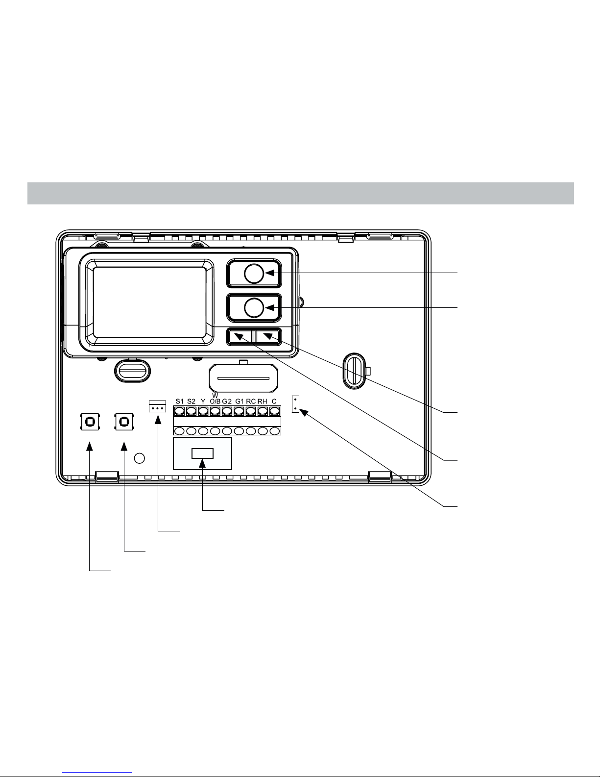
1
RESET CONFIG
RC
RH
Parts Diagram
Conguration switch
Reset switch
Left (system)
button
Right (fan)
button
Down button
Up button
Field programming pins
RC/RH jumper
FP
Fan Speed Switch
Page 4
2
Specifications
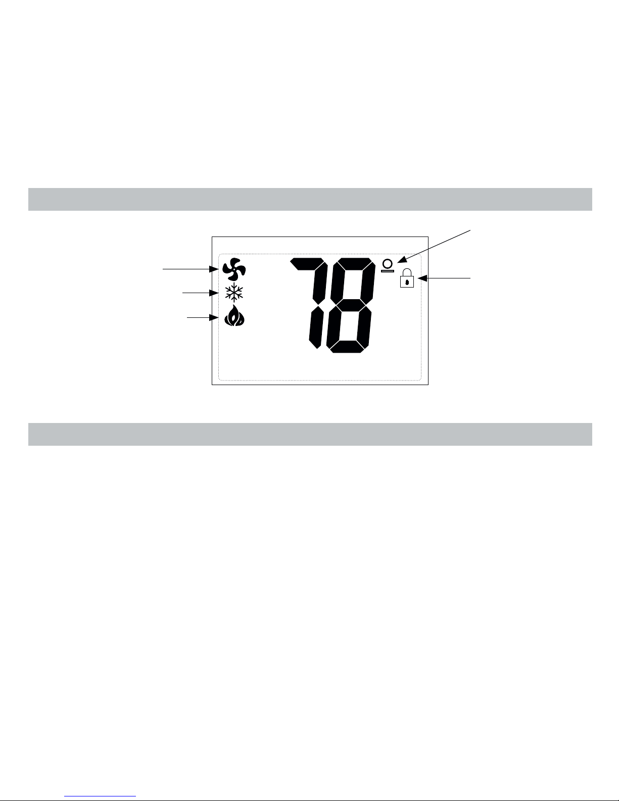
Icon Descriptions
Fan operation icon
Cooling operation icon
Heating operation icon
Lock mode
activated
Room
temperature offset
activated
Electrical rating: • 24 VAC (18-30 VAC)
• 1 amp maximum per terminal
• 3 amp maximum total load
Temperature control range: 45°F to 90°F (7°C to 32°C) Accuracy: ± 1°F (± 0.5°C)
System configurations: 1-stage heat, 1-stage cool, heat pump, gas, oil, electric
Timing:
Anti-short Cycle:
4 minutes
Backlight Operation
Terminations: S1, S2, Y, W/O/B, G2, G1, RC, RH, C
Page 5

3
Package Contents/Tools Required
Package includes: McQuay thermostat on base, thermostat cover, wiring labels, screws and wall anchors,
Installation, Operation and Application Guide
Tools required for installation: Drill with 3/16” bit, hammer, screwdriver
Important Safety Information
1. Turn off power to the heating and cooling system by removing the fuse or switching the appropriate circuit
breaker off.
2. Remove cover of old thermostat. This should expose the wires.
3. Label the existing wires with the enclosed wire labels before removing wires.
4. After labeling wires, remove wires from wire terminals.
5. Remove existing thermostat base from wall.
6. Refer to the following section for instructions on how to install this thermostat.
To Remove Existing Thermostat
WARNING
ELECTRICAL SHOCK HAZARD – Turn off power at the main service panel by removing the fuse or
switching the appropriate circuit breaker to the OFF position before removing the existing thermostat.
• This thermostat is for 24 VAC applications only; do not use on voltages over 30 VAC
• Do not short across terminals of gas valve or system control to test operation; this will damage your thermostat
and void your warranty
• All wiring must conform to local and national electrical and building codes
• Use this thermostat only as described in this manual
WARNING
Always turn off power at the main power supply before installing, cleaning, or removing thermostat.
Page 6

4
To Install Thermostat
IMPORTANT: Thermostat installation must conform to local and national building and electrical codes and
ordinances.
Note: Mount the thermostat about ve feet above the oor. Do not mount the thermostat on an outside wall, in
direct sunlight, behind a door, or in an area affected by a vent or duct.
1. Turn off power to the heating and cooling system by removing the fuse or switching the appropriate circuit
breaker off.
2. To remove cover, pull gently at the seam at the top.
3. Put thermostat base against the wall where you plan to mount it (Be sure wires will feed through the wire
opening in the base of the thermostat).
4. Mark the placement of the mounting holes.
5. Set thermostat base and cover away from working area.
6. Using a 3/16” drill bit, drill holes in the places you have marked for mounting.
7. Use a hammer to tap supplied anchors in mounting holes.
8. Align thermostat base with mounting holes and feed the control wires through slit in thermal intrusion barrier and
into wire opening.
9. Use supplied screws to mount thermostat base to wall.
10. Insert stripped, labeled wires in matching wire terminals.
WARNING
Be sure exposed portion of wires does not touch other wires.
WARNING
ELECTRICAL SHOCK HAZARD – Turn off power at the main service panel by removing the fuse or
switching the appropriate circuit breaker to the OFF position before removing the existing thermostat.
11. Gently tug wire to be sure of proper connection. Double check that each wire is connected to the proper
terminal.
12. Turn on power to the system at the main service panel.
Page 7
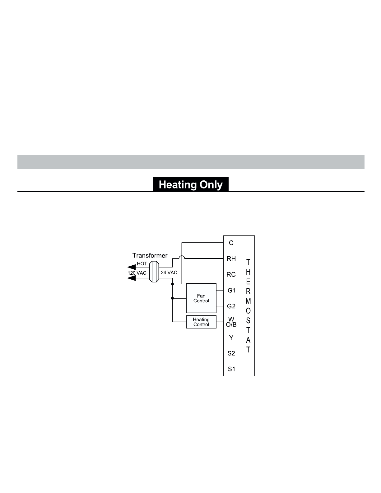
5
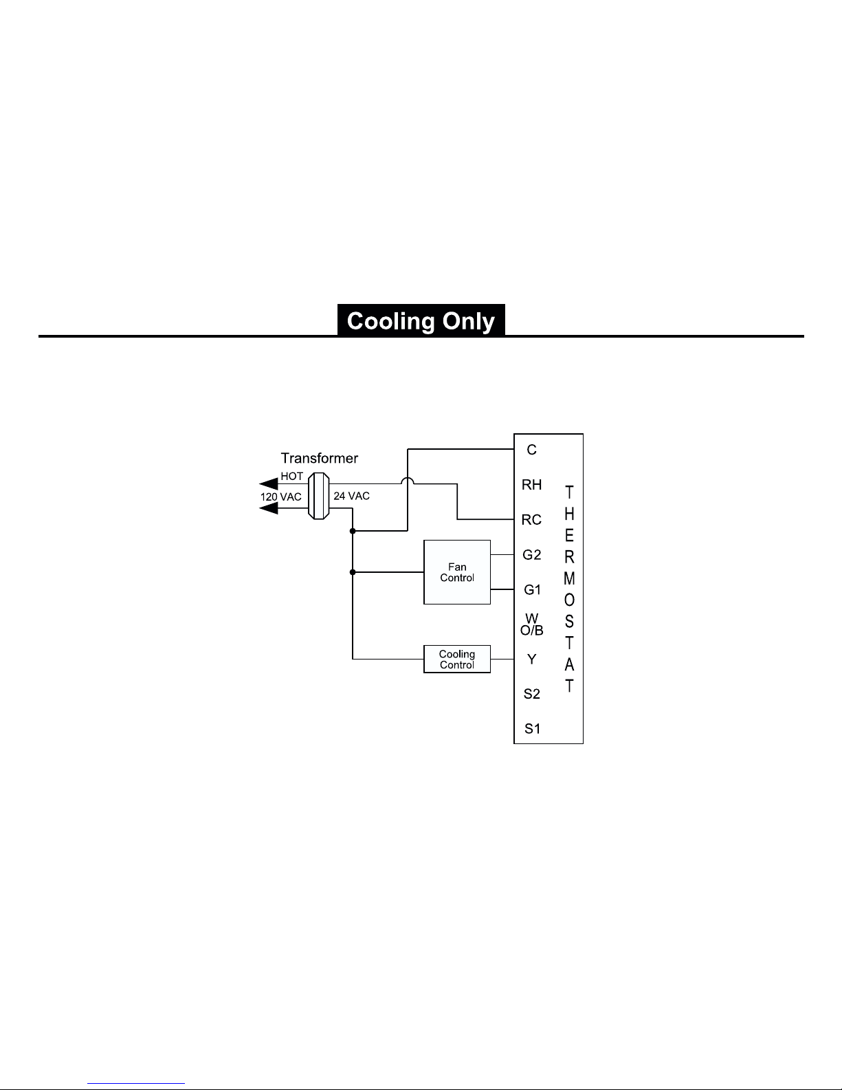
Hardwired
5-Wire, Single Transformer
Wiring Diagrams
13. Congure thermostat (see Page 12) to match the type of system you have.
14. Replace cover on thermostat by snapping it in place.
15. Test thermostat operation as described in “Testing the Thermostat” (Page 19).
Page 8

6
Hardwired
6-Wire, Two Transformer
(Both transformers must be in phase)
Hardwired
5 or 6-Wire, Single Transformer
IMPORTANT: Before wiring, remove pre-installed
RC/RH jumper.
Page 9
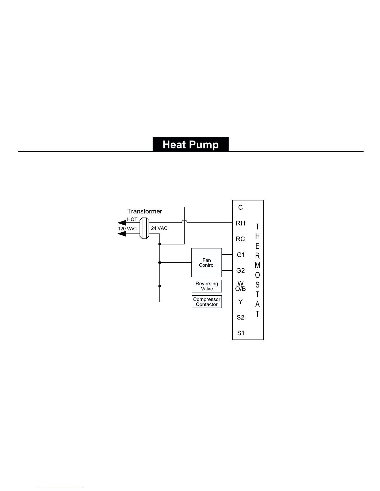
7
Hardwired
Cool or Heat Active Reversing Valve
Page 10
8
Hardwired
5-Wire, Single Transformer
Page 11

9
Remote or Outdoor Sensor Installation (Optional)
1. Remove cover from remote sensor housing.
2. Select an appropriate location for mounting the remote sensor.
3. Mount remote sensor unit using hardware provided.
4. Install two strand shielded wire between remote sensor and thermostat. Shielded wire must be used. Do not run remote
sensor wire in conduit with other wires.
• Wire 1 should run between the S1 terminal on the thermostat and the S1 terminal on the remote sensor
• Wire 2 should run between the S2 terminal on the thermostat and the S2 terminal on the remote sensor
• Connect the shielding of the wire to the S2 terminal on the thermostat
5. Congure the thermostat to operate with the remote sensor (see Conguration Mode setting 10, Page 14).
Note: Remote or outdoor sensor reading can be displayed by simultaneously pressing the Down and SYS
buttons.
Remote Sensor
(Optional)
Page 12

10
Configuration Mode
OFF
PM
1. Verify the McQuay thermostat is in the OFF mode.
Press the SYS (left) button until off mode displays.
2. Remove the cover of the thermostat by gently pulling near one of the corners at
the top of the thermostat.
3. Press the CONFIG button for 1 second while the McQuay thermostat is in OFF
mode.
To exit conguration mode, press the CONFIG switch for 1 second.
Press the up or down button to change settings within each screen.
Down
button
Up
button
Press the right button to advance to the next screen.
Note: Pressing the
left
button will return you to the previous screen.
Left
button
Right
button
The conguration mode is used to set the McQuay thermostat to match your heating/cooling system. The McQuay
thermostat functions with heat pump, air conditioning, gas, oil or electric heat systems.
To congure the McQuay thermostat, perform the following steps:
S1 S2 Y W
O/B
G RC RH C
RESET CONFIG
RC
RH
FP
CONFIG
Page 13

11
Configuration Mode Settings
The setup screens for Conguration Mode are as follows:
3. Deadband (1°F - 9°F) (1°C - 5°C)
Set the minimum number of degrees between your heat setpoint and your cool setpoint
in Autochangeover mode.
Press the up or down button to set deadband value.
Press the right button to advance to the next screen.
2. Temperature Differential (1°F to 5°F) (0.5°C to 2.5°C)
Set the number of degrees between your “setpoint” temperature and your “turn on”
temperature.
Press the up or down button to set differential value.
Press the right button to advance to the next screen.
1. Temperature Scale (F or C)
Choose Fahrenheit or Celsius.
Press the up or down button to select.
Press the
right
button to advance to the next screen.
Page 14

12
Press the up or down button to select.
Press the right button to advance to the next screen.
4. System – Set for heat pump, non-heat pump, reversing valve operation and number of compressors in your
system. Choose between two heat pump settings or gas/oil or electric.
Choose System
Reversing
Valve Active
Number of Compressors
or Compressor Stages
Type of
Heat
Heat Pump
HP O – Cool Active 1
HP b – Heat Active 1
Non-Heat
Pump
Heat Gas/Oil
Heat Electric
Page 15

13
5. Lockout (0-8°, NITE, COOL-HEAT)
Select the number of degrees set temperature can be changed during keypad lockout
or select to lockout during NITE period only. COOL-HEAT lockout allows adjustment
of the set temperatures to the maximum heat set temperature selected in Step 6 and
minimum cool set temperature selected in Step 7.
Note: The mode cannot be changed when the thermostat is locked.
Press the up or down button to select.
Press the right button to advance to the next screen.
6. Maximum Heat Setpoint (45°F to 90°F) (7°C to 32°C)
Adjust to control the maximum heat set temperature allowed.
Press the up or down button to select.
Press the right button to advance to the next screen.
7. Minimum Cool Setpoint (45°F to 90°F) (7°C to 32°C)
Adjust to control the minimum cool set temperature allowed.
Press the up or down button to select.
Press the right button to advance to the next screen.
Page 16

14
10. Temperature Sensor (1-4)
1. Only on-board sensor determines room temperature.
2. Only remote sensor determines room temperature.
3. Average temperature of on-board and remote sensor.
4. Only on-board sensor will be used until NITE period, and then only remote sensor
is used.
Press the up or down button to select.
Press the right button to advance to the next screen.
9. Maximum Cycles Allowed Per Hour (- -, 2-6)
- - = as many as needed, 2-6 = maximum cycles/hour
Press the up or down button to select.
Press the right button to advance to the next screen.
8. Room Temperature Offset (+9°F to -9°F) (+5°C to -5°C)
Adjust to calibrate displayed room temperature to match actual room temperature.
Note: When not set to 0, will display
Press the up or down button to select.
Press the right button to advance to the next screen.
Page 17

15
12. Status Indicator Light (Led 0 or 1)
0 = Status indicator never on
1 = Status indicator on with rst stage
Press the up or down button to select.
Press the CONFIG button for 2 seconds to exit conguration.
OFF
11. Cooling Fan Delay Off Time (0, 30, 60, 90 seconds)
Select the fan purge time for cooling.
Press the up or down button to select.
Press the right button to advance to the next screen.
Note: The McQuay control board provides a minimum Fan Off delay of 30
seconds, even if the thermostat is set for a 0 second delay.
Page 18

16
Mode of Operation
The McQuay thermostat is a programmable, manual or auto changeover, single-stage heat, single-stage cool
thermostat. It functions with air conditioning, heat pumps, gas, oil or electric heat systems.
The thermostat activates the heating appliance when the room temperature is below the set heat temperature
(by the differential temperature) and the red indicator light (congurable) on the thermostat will light. The McQuay
thermostat will stop outputting and the red light will turn off when the call for heat has been satised. With heat
pumps, the thermostat will not let the compressor come on for 4 minutes after it turns off. This protects your
compressor.
When the room temperature is greater than the set cool temperature (by the differential temperature), the cooling
device is activated and the green indicator light (congurable) on the thermostat will turn on. The McQuay thermostat
will stop outputting and the green light will turn off when the call for cooling is satised. The thermostat will not let the
compressor come on for 4 minutes after it turns off. This protects your compressor.
The McQuay thermostat has ve possible operating modes: OFF, Heat, Cool, Heat & Cool, and Program mode. In
off mode, the thermostat will not turn on heating or cooling devices. The manual fan can be turned on in all operating
modes using the fan button, and the fan speed can be set in all operating modes using the fan speed switch. In heat
mode, the thermostat controls the heating system. In the cool mode, the thermostat controls the cooling system. In
heat & cool mode, the thermostat controls both the heating and cooling systems. In program mode, the thermostat
will automatically be controlled by the set program. Program mode can function with heat mode, cool mode, or heat
& cool mode. The clock display alternates with the set temperature display for heat & cool mode.
The program schedule can be overridden by changing the set temperature (up or down button). This puts the
McQuay thermostat thermostat into a 2-hour temporary hold. After 2 hours, it will automatically return to the program
schedule.
The programmable fan feature can be used to recirculate air while in Program mode. It is activated during the
program schedule set up.
The McQuay thermostat also has a button lockout feature. This enables the thermostat to be set to the proper mode
and temperature and locked so it cannot be tampered with.
Page 19

17
Operating Modes
There are ve possible operating modes for the McQuay thermostat. Off, Cool, Heat, and Cool & Heat modes are
accessed by pressing the SYS (left) button. Program mode is accessed by pressing the SYS (left) and FAN (right)
buttons simultaneously.
OFF Mode
• In this mode, the thermostat will not turn on the heating or cooling devices
Note: The fan speed can be set in all operating modes using the fan speed
switch.
OFF
Heat Mode
• In this mode, the thermostat controls the heating system. When the heat outputs,
the ame icon
apprears on the display.
Note: For heat pumps, there is a four minute delay for your compressor to
restart after it has turned off.
Cool Mode
• In this mode, the thermostat controls the cooling system. When the cooling
outputs, the snowake icon
apprears on the display.
Note: There is a four minute delay for your compressor to restart after it has
turned off.
Page 20

18
PROG
PROG
PROG
Cool and Heat Mode (Auto Changeover)
• In this mode, the thermostat controls the cooling and heating systems, automatically
changing over from one to the other as needed.
• The timing display alternates with the set temperature every 10 seconds in the cool
and heat mode.
Program Mode
• In this mode, the program function is on (PROG displays), and the thermostat
will automatically be controlled by the set program schedule. Program mode can
function with heat mode, cool mode, or heat & cool mode. The program schedule
can be overridden by changing the set temperature (up or down button). After 2
hours, the program schedule will automatically be resumed. To manually return to
the program schedule, press the PROG button twice.
Page 21

19
Testing the Thermostat
Once the thermostat is congured, it should be thoroughly tested.
Heat Test
1. Press SYS (left) button until heat mode is displayed.
2. Adjust the set temperature so it is 5 degrees above the room temperature.
3. Heat should come on within a few seconds. Red LED may turn on.
4. Adjust the set temperature 2 degrees below the room temperature and the heat should turn off.
There may be a fan delay on your system.
Note:
For heat pumps, there is a four-minute delay to protect your compressor after it turns
off. To bypass the compressor time delay, go to OFF mode for 5 seconds.
PM
Cool Test
1. Press SYS (left) button until cool mode is displayed.
2. Adjust set temperature so it is 5 degrees below room temperature.
3. A/C should come on within a few seconds. Green LED may turn ON.
4. Adjust the set temperature 2 degrees above the room temperature and the A/C should turn off.
There may be a fan delay on your system.
Note:
There is a four-minute time delay to protect the compressor after it turns off.
To bypass the compressor time delay, go to OFF mode for 5 seconds.
PM
Fan Test
1. Press FAN (right) button. Fan displays. Indoor fan turns ON.
2. Press FAN (right) button. Indoor fan turns OFF.
PM
OFF
CAUTION
Do not energize the air conditioning system when the outdoor temperature is below 50 degrees.
It can result in equipment damage or personal injury.
Page 22

20
Setting the Time and Day of the Week
TODAY MON
5. Press the FAN (right) button once to select day of the week (TODAY ashing).
Press the up or down button to select current day of the week.
Note: At any time, press the SYS (left) button to return to the previous screen or
press the FAN (right) button to advance to the next screen.
Press the PROG button in for 2 seconds to lock values into memory and return to the
OFF mode or press the FAN (right) button once to enter programming.
4. Press the FAN (right) button once to select minutes (minutes ashing).
Press the up or down button to adjust the minutes.
3. Time displays (hour ashing).
Press the up or down button to adjust the hour.
2. Press and hold the PROG button (SYS (left) and FAN (right) buttons pressed
simultaneously) in for 6 seconds.
1. Press the SYS (left) button until you are in the OFF mode.
The time and day of the week must be set for your program schedule to operate correctly.
Page 23

21
Programming
Setting the program schedule:
1. Press the SYS (left) button until you are in OFF mode.
2. Press and hold the PROG button (SYS and FAN buttons pressed simultaneously) for 6 seconds.
3. Press the FAN (right) button 3 times.
4. SUN thru SAT are blinking.
SUN MON TUE WED THU FRI SAT
PROG
From this screen you have 2 options:
1. Press the FAN (right) button to begin programming all 7 days at one time, or
2. Press the
up
button to see the other programming options.
Note: The days of the week shown on the display will be programmed simultaneously.
The screens are listed below.
Screen 1 SUN MON TUE WED THU FRI SAT
Screen 2 MON TUE WED THU FRI
Screen 3 MON
Screen 4 TUE
Screen 5 WED
Screen 6 THU
Screen 7 FRI
Screen 8 SUN SAT
Screen 9 SAT
Screen 10 SUN
Program Overview
The McQuay programmable thermostat has four periods (MORN, DAY, EVE, NITE) that are customizable for each
day of the week. Each period will have a start time, heat temperature, cool temperature and programmable fan
option. The McQuay thermostat monitors the day and time, while maintaining the specic conditions you have
chosen for each period in your program.
Page 24

22
From any of the screens on Page 21, you can press the FAN (right) button to begin entering your program schedule.
The days shown on the display will all be programmed simultaneously.
Once the FAN (right) button is pressed, MORN blinks.
Use the up or down button to select a different period (MORN, DAY, EVE, NITE).
Press FAN (right) button to advance to the next screen. Transition time hour blinks.
Use the up or down button to select a different hour.
Press FAN (right) button to advance to the next screen. Transition time minutes blink.
Use the up or down button to select different minutes.
Press FAN (right) button to advance to the next screen. Heat set temperature displays.
Use the up or down button to adjust the heat set temperature.
Press FAN (right) button to advance to the next screen. Cool set temperature displays.
Use the up or down button to adjust the cool set temperature.
Press FAN (right) button to advance to the next screen. Programmable fan screen displays.
Use the up or down button to select:
Choose Off – Programmable fan disabled
On – Indoor fan on continuously
Note: Programmable fan operates in Program mode only.
Repeat above steps to program the four periods per day.
When the program schedule is complete, press and hold the PROG button (SYS and FAN buttons pressed
simultaneously) in for 2 seconds to return to the OFF mode.
Page 25

23
Lockout Feature
The McQuay thermostat has a button lockout feature so the mode cannot be changed
and the temperature adjustment is limited. Select the appropriate lockout from
Conguration Mode Settings (Step 5, Page 13) of this guide.
To activate the LOCK feature:
1. Simultaneously press the SYS, FAN and UP buttons for 10 seconds.
2.
will display and the lockout function will be enabled.
To deactivate the LOCK feature, repeat steps 1 and 2 above.
Page 26

24
Factory Preprogramming
MORN 6:00 AM DAY 8:00 AM EVE 6:00 PM NITE 10:00 PM
HEAT 70°F HEAT 62°F HEAT 70°F HEAT 62°F
COOL 78°F COOL 85°F COOL 78°F COOL 82°F
FAN Off FAN Off FAN Off FAN Off
MONDAY
thru
SUNDAY
Personal Program Schedule
MORN DAY EVE NITE
HEAT HEAT HEAT HEAT
COOL COOL COOL COOL
FAN FAN FAN FAN
MONDAY
1
TUESDAY
2
MORN DAY EVE NITE
HEAT HEAT HEAT HEAT
COOL COOL COOL COOL
FAN FAN FAN FAN
WEDNESDAY
3
MORN DAY EVE NITE
HEAT HEAT HEAT HEAT
COOL COOL COOL COOL
FAN FAN FAN FAN
Use the following personal program schedule to record your settings:
The McQuay thermostat comes preprogrammed with the following schedule
:
Page 27

25
Personal Program Schedule (continued)
THURSDAY
4
FRIDAY
5
SUNDAY
7
SATURDAY
6
MORN DAY EVE NITE
HEAT HEAT HEAT HEAT
COOL COOL COOL COOL
FAN FAN FAN FAN
MORN DAY EVE NITE
HEAT HEAT HEAT HEAT
COOL COOL COOL COOL
FAN FAN FAN FAN
MORN DAY EVE NITE
HEAT HEAT HEAT HEAT
COOL COOL COOL COOL
FAN FAN FAN FAN
MORN DAY EVE NITE
HEAT HEAT HEAT HEAT
COOL COOL COOL COOL
FAN FAN FAN FAN
Page 28

26
SimpleSetTM Field Programming
This feature is used for transferring conguration and program schedule from the master to the target thermostat.
All thermostats for a job can be mounted and powered up. Congure and program one thermostat. This will be the
master. The master will be used to copy the program to the rest of the thermostats.
Preparing the master to Send:
1. The master must be powered with 24 VAC.
2. Verify the master thermostat is in OFF mode.
3. Press SYS (left) button until OFF mode displays.
4. Remove cover of the master thermostat by gently pulling near one of the corners at the top
of the thermostat.
5. Press the up and down buttons and CONFIG switch simultaneously for 5 seconds.
6. The OUT screen displays indicating the master thermostat is ready to transfer data.
Note: Press the up and down buttons and CONFIG switch simultaneously for 5
seconds to exit from data transfer mode and to return the master to the OFF
mode.
7. Turn off power to the master and remove it from the wall.
8. Connect the master to the target using the 3 wire connector. Attach one end to the Master’s
FP pins and the other end to the Target’s FP pins.
Note: Target thermostat must be powered with 24 VAC for eld
programming to occur
When the connection has been made correctly, the master thermostat will power up and the target will count from 5
down to 1. It will then display the LOCK conrming the data has been saved in memory.
When all target thermostats have been completed, reinstall the master thermostat.
Press the up and down buttons and the CONFIG switch simultaneously for 5 seconds to exit from the data transfer
mode and to return the master thermostat to the OFF mode.
OFF
FP pins
S1 S2 Y W
O/B
G RC RH C
RESET CONFIG
RC
RH
FP
Requires SimpleSetTM Transfer Cable (668817901)
Page 29

27
Troubleshooting
Symptom Remedy
No display Check for 24 VAC at thermostat; display is blank when 24 VAC is not present
Time and day of week must be reset after extended power loss
System fan does not come on properly Verify wiring is correct, check Gas/Electric Conguration (see Setting 4, Page 12)
All thermostat buttons are inoperative Verify 24 VAC is present; unit locks out when 24 VAC is not present
No response with rst button press First button press activates backlight only
Program schedule activates at the wrong time Check time (AM/PM) set on thermostat (see Setting the Time, Page 20)
Thermostat turns on and off too frequently Adjust temperature differential (see Conguration Mode Setting 2, Page 11)
Thermostat does not follow program Verify it is operating in program mode (PROG displays); check time (AM/PM); check if in 2
hour program override
Fan runs continuously Press FAN (right) button to turn fan off
Fan turns on occasionally
Program Mode: Check programmable fan setting in program schedule
(see Page 22)
Status indicator light not on during call Turn status indicator function on (see Conguration Mode Setting 12, Page 15)
Room temperature is not correct Calibrate thermostat (see Conguration Mode Setting 8, Page 14)
If remote sensor is used, check S1 and S2 terminal connections
displays when any button is pressed Thermostat has the button lockout function activated (see Lockout Feature, Page 23 and
Conguration Mode Setting 5, Page 13)
on display instead of room temp. Check for a bad connection at S1 and S2 terminals, if used (see Conguration Mode Setting
10, Page 14)
Heat or Cool not coming on Verify wiring is correct, verify RC/RH jumper is in place (for single transformer system)
Remote or outdoor sensor not accurate Press SYS and Down buttons simultaneously to display remote or outdoor temperature. Verify
connections at S1 and S2 terminals.
Problem not listed above Press Reset button once*
* Reset Button Function:
Time and day are reset, conguration and program settings are unchanged.
Page 30

This page left blank intentionally.
Page 31

This page left blank intentionally.
Page 32

McQuay Training and Development
Now that you have made an investment in modern, efcient McQuay equipment, its care should be a high priority.
For training information on all McQuay HVAC products, please visit us at www.mcquay.com and click on training, or
call 540-248-9646 and ask for the Training Department.
Warranty
All McQuay equipment is sold pursuant to its standard terms and conditions of sale, including Limited Product
Warranty. Consult your local McQuay Representative for warranty details. Refer to Form 933-43285Y. To nd your
local McQuay Representative, go to www.mcquay.com.
This document contains the most current product information as of this printing. For the most up-to-date product
information, please go to www.mcquay.com.
LIA303 / Version B: 03-23-09
For replacement parts call 1-800-377-2787
©2008 McQuay International • www.mcquay.com • 800-432-1342
 Loading...