

Page 1
Installation and Maintenance IM 254-5
Hi-Line™ Fan Coil Unit
Model KZZ S03 through S08
Group: Fan Coil
Part Number: 667754200
Date: December 2005
© 2005 McQuay International
Page 2

Contents
General Information . . . . . . . . . . . . . . . . . . . . . . . . . . . . . . .1
Receiving and Handling . . . . . . . . . . . . . . . . . . . . . . . . . . . . . .1
Installation . . . . . . . . . . . . . . . . . . . . . . . . . . . . . . . . . . . . . . . . .2
Risers (Field supplied & installed) . . . . . . . . . . . . . . . . . . . . . .2
Installation . . . . . . . . . . . . . . . . . . . . . . . . . . . . . . . . . . . . . . . . .3
Cabinet . . . . . . . . . . . . . . . . . . . . . . . . . . . . . . . . . . . . . . . . . . .3
Furring In . . . . . . . . . . . . . . . . . . . . . . . . . . . . . . . . . . . . . . . . .6
Wiring . . . . . . . . . . . . . . . . . . . . . . . . . . . . . . . . . . . . . . . . . . . .6
Ducts . . . . . . . . . . . . . . . . . . . . . . . . . . . . . . . . . . . . . . . . . . . .6
Finishing . . . . . . . . . . . . . . . . . . . . . . . . . . . . . . . . . . . . . . . . . .6
Twin Units Installation . . . . . . . . . . . . . . . . . . . . . . . . . . . . . . . 7
Wiring Diagrams . . . . . . . . . . . . . . . . . . . . . . . . . . . . . . . . . . 9
Start-Up . . . . . . . . . . . . . . . . . . . . . . . . . . . . . . . . . . . . . . . . . . 11
Maintenance . . . . . . . . . . . . . . . . . . . . . . . . . . . . . . . . . . . . . 12
Filters . . . . . . . . . . . . . . . . . . . . . . . . . . . . . . . . . . . . . . . . . . 12
Drain Pans . . . . . . . . . . . . . . . . . . . . . . . . . . . . . . . . . . . . . . 12
Fan Motor . . . . . . . . . . . . . . . . . . . . . . . . . . . . . . . . . . . . . . . 12
Coil . . . . . . . . . . . . . . . . . . . . . . . . . . . . . . . . . . . . . . . . . . . . 12
Service . . . . . . . . . . . . . . . . . . . . . . . . . . . . . . . . . . . . . . . . . . . 13
Fan and Motor Removal . . . . . . . . . . . . . . . . . . . . . . . . . . . . 13
Electric Heater Troubleshooting . . . . . . . . . . . . . . . . . . . . . . 13
Electric Heater Removal . . . . . . . . . . . . . . . . . . . . . . . . . . . . 13
McQuay and MicroTech II are registered trademarks of McQuay International.
Copyright © 2005 McQuay International. All rights reserved throughout the world.
Page 3
General Information
McQuay HiLine fan coil air conditioning units are designed
for use in multiple floor apartments, office buildings, hotels,
and other similar applications. They require a minimum
amount of floor space and one unit may do the job that
formerly required more than one conventional unit.
The 300 through 800 cfm, blow-through configuration units
described in this manual are designed to meet individual room
control requirements. Two-pipe and four-pipe systems are
available, with single, double, triple, and top discharge
arrangements. Optional equipment is available to provide
complete application flexibility.
Installation and maintenance must follow accepted industry
practices as described in the ASHRAE Handbook, the National
Electric Code, and other applicable s t a n da r d s . Install this
equipment in accordance with regulations of authorities having
jurisdiction and with all applicable codes.
Installation and maintenance must be performed by qualified
personnel familiar with applicable codes and regulations and
experienced with this type of equipment.
CAUTION
SHARP EDGES ON SHEET METAL AND COIL SURFACES
if not avoided could result in cuts.
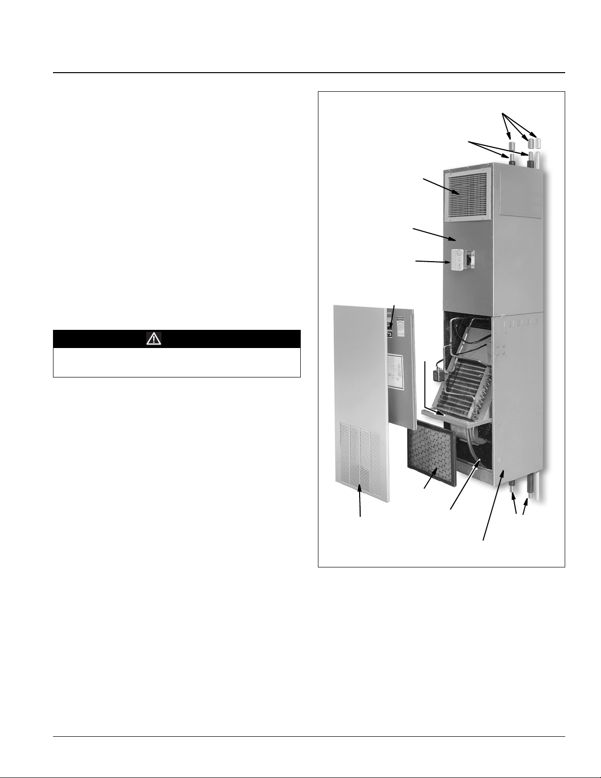
Figure 1: HiLine fan coil unit
Couplings
Risers
Discharge Air
Top Plenum
Cabinet
Controls
Access panel and
sound baffle
Coil
Receiving and Handling
Carefully check items against the bills of lading to verify all
crates and cartons have been received. The units normally ship
four to a pallet.
Carefully inspect all units for shipping damage. Report
damage immediately to the carrier and file a claim.
Check the electrical nameplate to be sure it agrees with the
power supply available.
DO NOT handle units by the riser piping. Riser clamps hold
the riser in position; they are not designed to support the
cabinet weight. They are removed after the unit is installed.
Filter
Return air grille panel
Motor and fan
assembly
Bottom Cabinet
Risers
Units are shipped with the top plenum cabinet and top plenum
front panel not assembled to the lower cabinet. KZZ units are
factory wired and have individual thermostat controls. They
are installed by stacking one unit on top of the other. While
installing, prevent dirt and other foreign matter from entering
the risers and plugging lines or valves.
McQuay IM 254-5 1
Page 4
Installation
Risers (Field supplied & installed)
The coupling stub-outs must be properly positioned so that the
coil connections will line up when the units are placed in
position. Construct a fixture to maintain dimensions shown in
figure 2, during the soldering process.
• If field-supplied isolator pads are used, install them now.
This additional thickness must be considered before
installation of risers.
• The unit has provisions for plus or minus one inch of vertical
movement of risers. If the riser system movement exceeds
this value, compensating provisions must be provided by the
installing contractor.
• Anchor risers to the building structure to prevent vertical
riser movement greater than ±1" (25mm) due to riser
expansion or contraction. (Anchors by others).
CAUTION
The unit is not designed to support the weight of the risers.
Anchor them securely to the building structure.
Figure 2: Risers and stub-outs locations
• Care must be taken to prevent dirt and other foreign matter
from entering the risers as clogged lines or valves could
result.
• Close all ball valves on the coupling stub-outs and cement
joints to avoid condensation problems.
• Apply insulation to stub-outs and cement joints to avoid
condensation problems.
To c omply with existi ng building codes, the installing contractor must
restore the original fire resistance rating of the structure by sealing the
access space around the risers with material having the same fire
rating as the structure. This procedure is very important so that a seal
is provided between floors to prevent the passage of warm, humid air
which can cause condensation on riser insulation. This is most critical
in unpressurized buildings with high infiltration rates.
2 McQuay IM 254-5
Page 5
Installation
Cabinet
1 Carefully separate the top plenum cabinet from the lower
cabinet so as not to tear the fiberglass insulation.
See Figure 3.
2 Separate the top plenum front panel from the lower cabinet.
3 The fasteners and parts needed for assembly are located in
the base of the lower cabinet. Remove the riser blockoffs,
sight baffle (if required), and the valve package supports.
The filter is located above the coil. See Figure 3.
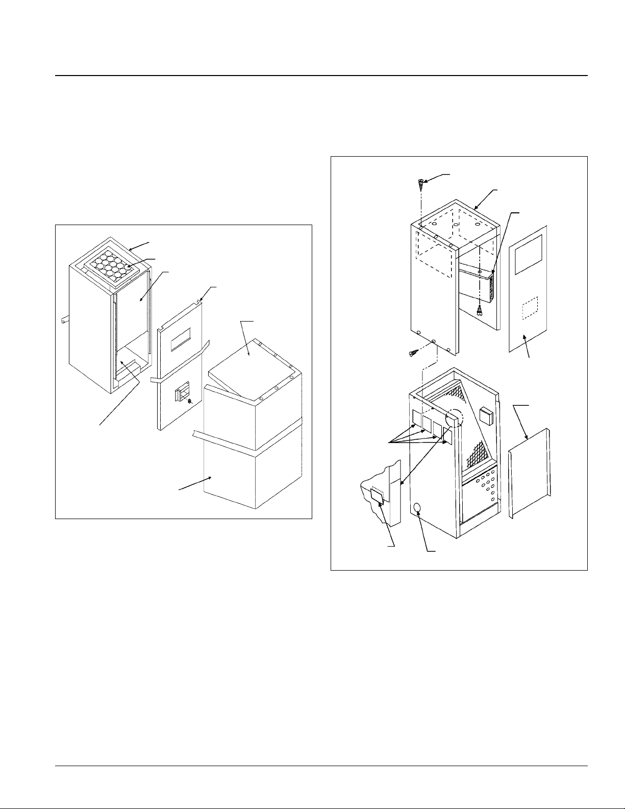
Figure 3: Unit preparation for field assembly
Lower Cabinet
Filter
Serial Plate & Coil Location
Top Plenum Cabinet-
Front Panel
Top Panel
11 With the unit in the final location, check level to insure
proper condensate drainage and operation.
12 Fasten the top panel of the plenum by installing the three
sheet metal screws “A”. See Figure 4.
Figure 4: Installation of top plenum cabinet
“A”
Top Plenum Cabinet
Optional
Sight Baffle
Top Plenum Cabinet-
Front Panel
Fasteners & Parts
Location
Top Plenum Cabinet
4
Bend out the tabs used to support the top plenum cabinet to
the lower cabinet as shown in Figure 4.
5 Remove the appropriate riser and drain knockouts in the
lower cabinet. See Figure 4.
6 Slit the fiberglass insulation within the riser knockout
openings to allow the riser valves to protrude into the lower
cabinet.
7 Position the riser blockoffs over the riser stub-outs. See
Figure 5 on page 4.
8 Position the lower cabinet so it aligns properly with the
risers. See Figure 6b. Align the horizontal stub-outs so they
are centered within the knockout openings in the cabinet.
This is important to allow riser expansion and contraction
of plus or minus one inch.
9 Solder connections if sweat valves have been supplied.
10 Attach plastic drain hose to drain line. Be sure hose clamp
is properly installed.
Front Access
Panel
Riser Knockouts
(All Sides)
Support Tabs
13 Install the sight baffle (if required) to the top as shown in
Drain Knockout (All Sides)
Figure 4.
14 Place the top plenum cabinet on the lower cabinet. See
Figure 4 & 6c.
15 Fasten the top plenum cabinet to the lower cabinet with
sheet metal screws. See Figure 4.
16 Attach the top plenum cabinet - front panel to the top
plenum cabinet with sheet metal screws enclosed.
McQuay IM 254-5 3
Page 6

Figure 5: Riser blockoff placement Figure 6: Installation overview
6a. Leak test and insulate
risers and stub-outs
prior to unit placement.
6b.Position the lower
cabinet so it aligns
properly with the risers
and stub-outs. Solder
the supply and return
connections. Attach
plastic drain hose to
drain line.
6c. Place the top plenum
cabinet on the lower
cabinet and fasten with
sheet metal screws.
Installation
6d.Unit “furred in” with
grille attached and
thermostat wired.
6e. Completely installed
unit.
McQuay IM 254-5 4
Page 7

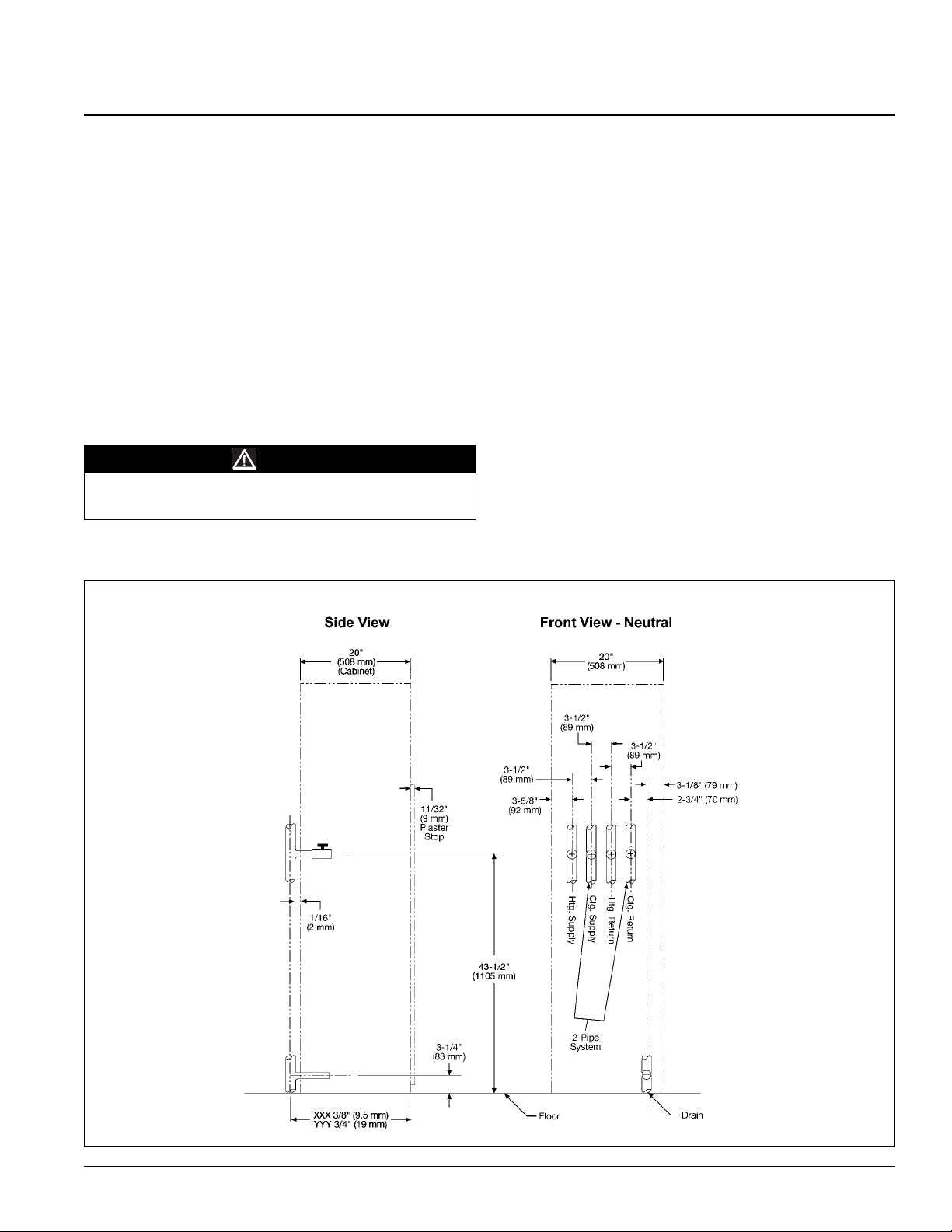
Figure 7: Dimensional details
Installation
Neutral Hand Unit Shown
Hand of unit determined by facing return air opening.
Risers on right = Right hand unit.
Risers on left = Left hand unit.
Risers on back = Neutral unit.
Note – (1) With return air grille mounted on unit, dimension becomes 2-3/8”.
(2) Can be field adjusted to 3-7/8” for furred-in application.
McQuay IM 254-5 5
Page 8

Installation
Furring In
1 When furring in units, make sure no screws or nails
penetrate the unit cabinet, other than grille or plaster frame
attaching screws. Grille or plaster frame attaching screws
should not penetrate the cabinet more than 2" (51 mm).
2 The thermostat box can be positioned up to 3 7/8" (98 mm)
from the unit for furring in. The mud ring can be positioned
vertically or horizontally and has 2" x 4" opening. (see
Figure 7).
3 If the wall board or other wall material does not fit flat
against the face of the unit, install field-supplied extension
sleeves for both the return and supply air openings.
Wiring
The complete unit system wiring diagram is located on the
front of the access panel. Wire in accordance with local codes
or the National Electrical Code, whichever is applicable.
1 Provide branch circuit overcurrent protection and
disconnect means.
2 Bring electrical wiring through the side of the cabinet into
the wiring box located on the right side of the cabinet (see
Figure 7 Side View) using the two 7/8" (22 mm) diameter
knockouts.
3 When routing wiring through the cabinet, make sure the fan
remains accessible for possible removal.
4 Connect control wiring to the unit-mounted thermostat and
fan switch or a remote mounted control.
5 A 10 K thermistor is mounted on all units for sensing return
air temperatures. The sensor on the remote-mounted
thermostat may also be used for this purpose.
6 Rotate the fan wheel by hand to make sure it rotates freely.
• Design the ducts for velocities in accordance with the
methods outlined in the ASHRAE guidebooks.
• Control airborne noise by installing sound attenuating
materials and by installing flexible connections between the
unit and ductwork.
Finishing
1 Attach the return air grille plaster frame on the opening
over the top of the wall board. Use the wall board frame as
a template to drill pilot holes into the wall or unit for the
attaching screws (see Figure 8).
Note – Mount the plaster frame with the corners square so that
the grille panel will fit over it properly.
2 Attach the supplied retaining clips to the plaster frame
adjacent to the lower attaching screws (see Figure 9 on
page 7).
Figure 8: Grille panel with plaster frame
Ducts
If ducts are added:
• Install in accordance with NFPA 90A and 90B.
• Check that the resistance is within the limits of the external
static pressures shown in the catalog for the particular unit
being installed.
6 McQuay IM 254-5
Page 9

Figure 9: Plaster frame retaining clip installation
Installation
Twin Units Installation
Twin opposite hand units share a common riser system; i.e.,
supply, return, and drain riser. This is commonly called a
“master/slave” arrangement. The master unit is shipped with
the risers attached. These special risers have stub-outs which
must be field connected to the slave units. In addition to the
instructions in bulletins IM 254 (KZZ units) or IM 255 (HSS
units), the following procedures must be followed for all twin
unit installations.
1 The slave unit has no risers and no stub-outs. Knockout
holes are provided for internal piping connections.
2 HSS-S10 and -S12 units will not match up with the smaller
units sizes S03, S04, S06 and S08 due to differences in riser
stub-out locations.
3 Master units are offered in two-pipe or four-pipe systems
with either right-hand or left-hand connections. Slave units
are offered to accommodate internal connections to any of
these riser systems or locations.
4 The riser location (right or left) is determined by facing the
return air grille panel. The risers are located on either the
right or left of the unit. This defines the riser location. See
Figure 10.
Figure 10: HiLine Twin Unit Arrangements
Right-Hand
Master
Wall
Left-Hand
Slave
Note–Arrows refer to return air panel position.
5
The riser block-off plates are located in the base of the
Left-Hand
Master
Right-Hand
Slave
slave unit. Block-offs must be installed on the slave unit
before putting it into position. (see Figure 5 on page 4).
6 Install the master unit per IM 254 or IM 255.
7 Recommended wall opening locations for the slave unit
risers and stub-outs are shown in Figure 2 on page 2.
8 The openings must provide enough space to allow easy
installation of the unit. During installation, the unit is tilted
at an angle to set into place. Unless the opening in the wall
is large enough, there will be interference and the unit
cannot be set into position.
9 Openings must be large enough to accommodate riser stubs
with foam insulation. An allowance must be made for
insulation thickness, fitting connections, and hand valves
on the stub-outs.
McQuay IM 254-5 7
Page 10

Installation
10
The opening in the wall must provide space for vertical
movement of riser stubs as a result of riser expansion and
contraction.
11 The slave unit piping terminates with 5/8" sweat
connections. The piping is also supported inside the cabinet
to prevent any damage to them during shipment. This
support bracket must be removed to allow expansion or
contraction in the piping after unit is installed.
12 The ball valves are not factory mounted to the slave unit
piping because there would be insufficient room between
ball valve and cabinet to make field connections to the unit.
The ball valves (quantity 2 on two-pipe, 4 on four-pipe), if
ordered from McQuay, will be shipped in a separate box.
The correct installation procedure, as outlined in
subsequent paragraphs, is to first mount the ball valves to
the riser stub-outs and then set the slave unit in place with
the ball valves protruding through the slave unit riser
knockouts. The connections can then be made between ball
valves and unit piping within the HiLine slave unit.
13 The length of tubing between the 5/8" O.D. slave unit stub-
out and the hand valve for the slave unit is to be provided
by the contractor. The length will be determined by the
dimension between the walls.
After the master unit is set in place, the field supplied
tubing should be sweated to the riser stub-outs and ball
valves sweated to the field supplied tubing. Hand valves
should be closed and risers pressurized to locate any leaks.
Leaks should be repaired before slave units are installed
and access is restricted.
14 Stub-outs from the supply and return risers are on center
from the bottom of the unit. They are to be made of copper
tubing. The standard stub-out length is 2 3/4" (70 mm)
beyond the outside diameter of the riser.
15 The drain stub-out is either 1/2" PVC or 5/8" O.D. copper,
depending on which was ordered for the job.
16 Slave unit stub-outs should be well insulated by the
contractor to prevent condensation problems.
17 Remove the appropriate riser and drain knockouts in the
lower cabinet of the slave unit.
18 Slit the fiberglass insulation so that the riser ball valves can
be pushed through and into the slave unit.
19 Install the slave unit riser block-off plates as shown in
Figure 5 on page 4.
20 Position the slave unit to the hand valves. The horizontal
stub-outs should be centered in the opening in the cabinet.
21 Solder connections if sweat valves have been supplied.
22 Attach plastic drain hose to the drain line. Be sure hose
clamp is properly installed and that there are no kinks in the
hose.
23 With unit in final location, check level to provide proper
condensate drainage and operation.
24 Use IM 254 or IM 255 to complete the installation of the
slave unit.Figure 10 shows a typical example of a master/
slave arrangement for a two-pipe system. For four-pipe
master/slave riser location, refer to Certified Drawing CDFC-KZZ 03-08 Specs.
8 McQuay IM 254-5
Page 11

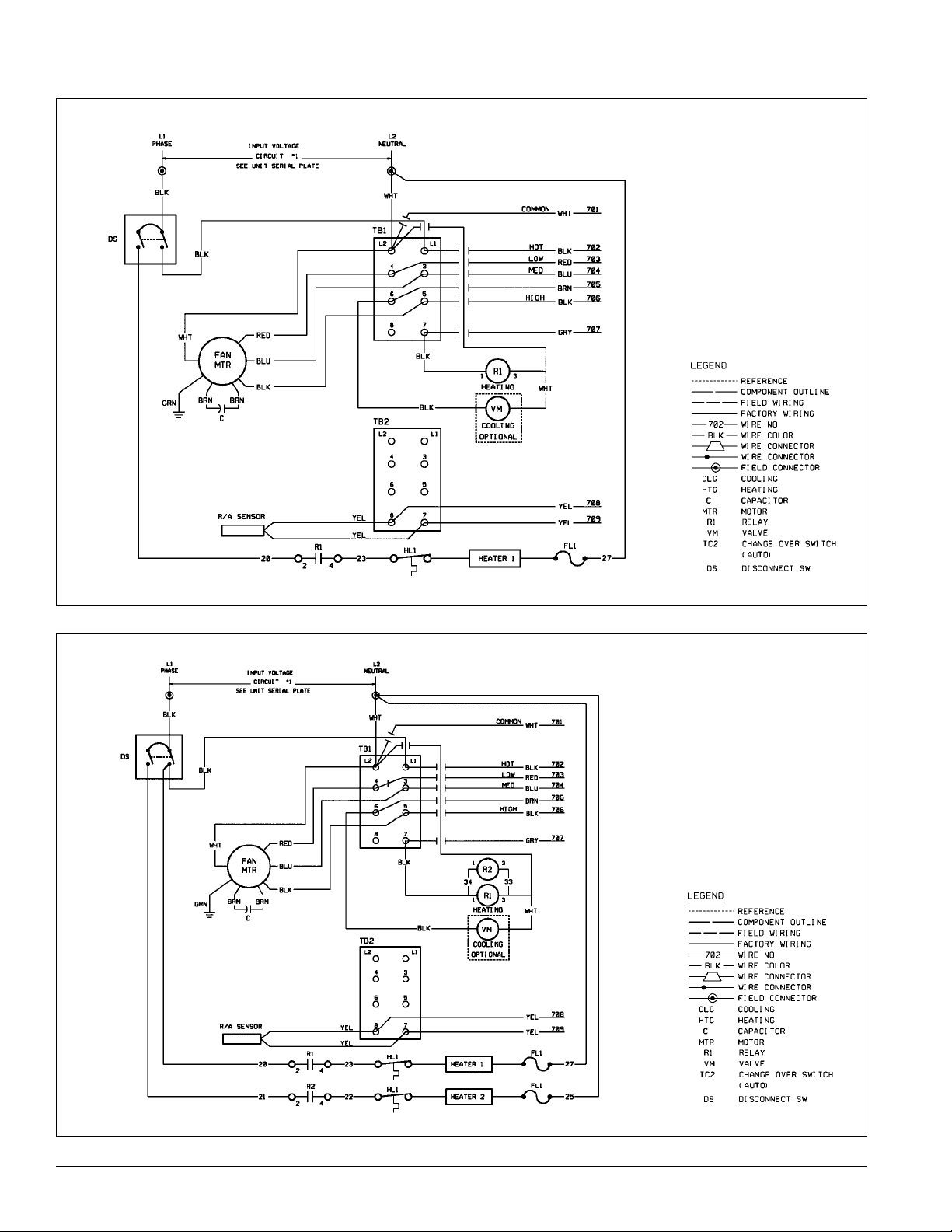
Wiring Diagrams
Figure 11: 2-Pipe (041538651)
Figure 12: 4-Pipe (041538652)
McQuay IM 254-5 9
Page 12
Wiring Diagrams
Figure 13: 2-Pipe with 1 circuit electric heat (041538653)
Figure 14: 4-Pipe with 2 circuit electric heat (041538654)
10 McQuay IM 254-5
Page 13

Start-Up
CAUTION
Prior to unit start-up, make sure no foreign material remains in
the unit, paying particular attention to the drain pan and drain
line. Blocked drains can result in drain pan water overflow.
1 Remove all foreign material from unit.
2 Open supply and return water service valves.
3 If the unit does not have the automatic flow control option,
balance the water flow rate with the hand valve on the
return line.
4 Install the front access panel.
5 Put the filter into position.
6 Install the return air grille.
7 Close all windows and doors.
8 Switch the unit to ON and check for proper operation of
fans, fan speed switch, and thermostat.
Note – When there is a high amount of moisture in the air, this
initial pull down should be gradual to reduce the
possibility of unit sweating (i.e., high fan speed for
maximum air flow with reduced GPM and elevated chilled
water temperature for reduced capacity). Do not operate
outside air supplies or toilet exhaust systems until the
gradual pull down is complete.
McQuay IM 254-5 11
Page 14

Maintenance
Filters
• Clean filters to obtain maximum unit performance.
• Inspect filters every three or four months under normal
operating conditions and replace when necessary.
• Do NOT operate units without a filter.
Drain Pans
• In areas where airborne bacteria or other microorganisms are
known to produce growth in the drain pan, treat the water
chemically to minimize the problem. Contact your local
McQuay representative or one of the many companies
dealing with water conditioning.
• The condensate drain pan can pick up lint and dirt,
especially with dirty filters. Inspect the drain pan twice a
year to avoid the possibility of overflow.
Fan Motor
Note – The fan motor is oiled at the factory. Under continuous
• Oil the fan motor every six months with one teaspoon or 5 cc
operation; it is not necessary to oil it in the first six
months.
per bearing of SAE No. 20 nondetergent oil. Do NOT
overlubricate.
Coil
• The coil must be clean to obtain maximum performance.
• Check the coil once a year, under normal operating
conditions. If it is dirty, brush or vacuum clean. Take care
not to damage the aluminum fins while cleaning.
CAUTION
SHARP EDGES ON SHEET METAL AND COIL SURFACES
if not avoided could result in cuts.
McQuay IM 254-5 12
Page 15

Service
WARNING
Before removing or replacing any component, lock out and tag
out all power to the unit. Live electrical components, fans and
belts can cause severe personal injury or death.
Fan and Motor Removal
If fan or motor service is required, remove th e fan motor through
the return air opening as follows:
1
Shut off electrical power to the unit.
2
Remove the return air grille panel.
3
Remove the front access panel.
4
Disconnect the fan motor leads at the wiring box.
5
To reassemble, reverse the above steps.
To reassemble, reverse the above steps.
Electric Heater Troubleshooting
McQuay electric heater elements, if furnished, are designed with a
high limit control set to trip when cabinet temperatures reach
175°F and automatically reset when cabinet temperatures drop to
140°F.
If the high limit temperature is tripping, the unit is not performing
properly. Some probable causes are
•
Not enough air over the heater due to dirty filter
•
Fan motor not operating
•
Dirty coil
•
Fan wheel loose on the motor shaft
•
Loose electrical connections
Electric Heater Removal
If the electric heater requires service, remove it as follows:
1
Shut off electrical power to the unit.
When requesting service or replacement parts, direct your
inquiries to McQuayService. Refer to the model number and
the serial number of the heater stamped on the serial plate
attached to the heater kit. If replacement parts are required,
provide the date of the heater kit installation and the date of the
failure. Also, describe the part being replaced and explain its
malfunction.
Figure 15: Replacing high limit control or heater detail
McQuay IM 254-5 13
Page 16

McQuay Training and Development
Now that you have made an investment in modern, efficient McQuay equipment, it s care should be a high priority.
For training information on all McQuay HVAC products, please visit us at www.mcquay .com and click on train ing, or
call 540-248-9646 and ask for the Training Department.
Warranty
All McQuay equipment is lold pursuant to its standard terms and conditions of sale, including Limited Product
Warranty. Consult your local McQuay Representative for warranty details. Refer to Form 933-43285Y. To find your
local McQuay Representative, go to www.mcquay.com.
This document contains the most current product information as of this printing. For the most up-to-date product
information, please go to www.mcquay.com.
Products Manufactured in an ISO Certified Facility.
© 2005 McQuay International • www.mcquay.com • 800-432-1342 12/05
 Loading...