

Page 1
Installation & Maintenance Data IM 254-4
Group: Fan Coil
Part Number: 107133000
Date: June 1999
SeasonMaker
™
HiLine Fan-coil Units
Type KZZ
Contents
Inspection . . . . . . . . . . . . . . . . . . . . . . . . . . . . . . . . . . . . . 2
Riser Installation . . . . . . . . . . . . . . . . . . . . . . . . . . . . . . . . 2
Unit Installation . . . . . . . . . . . . . . . . . . . . . . . . . . . . . . . 3, 4
Start-up . . . . . . . . . . . . . . . . . . . . . . . . . . . . . . . . . . . . . . . 7
Maintenance . . . . . . . . . . . . . . . . . . . . . . . . . . . . . . . . . . . 8
Service . . . . . . . . . . . . . . . . . . . . . . . . . . . . . . . . . . . . . . . 8
Replacement Parts . . . . . . . . . . . . . . . . . . . . . . . . . . . . . . 8
©1999 McQuay Incorporated
Page 2
Installation and maintenance are to be performed only by qualified personnel who are familiar with and in
compliance with state, local and national codes and regulations, and experienced with this type of equipment.
Caution: Sharp edges and coil surfaces are a potential injury hazards. Avoid contact with them.
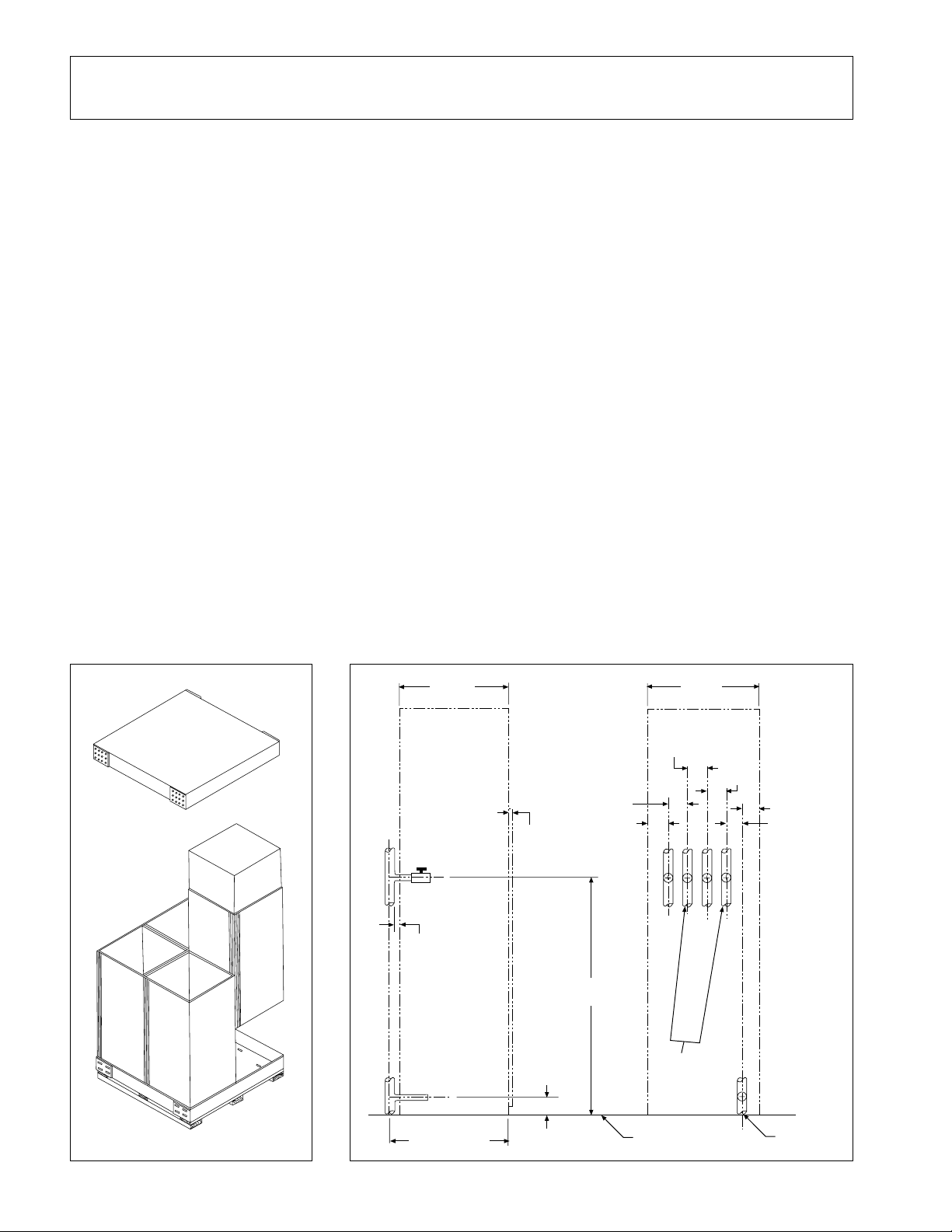
Inspection
When the equipment is received, all items must be carefully
checked against the bill of lading to be sure all crates and
cartons have been received. The units are shipped four to a
pallet. Visible or concealed damage should be reported
Riser Installation
(Field Supplied & Installed)
1. It is critical that the coupling stub-outs are properly
positioned so that the coil connections will line up when
the units are placed in position. See Figure 2. It is recommended that a fixture be constructed to maintain dimensions shown in Figure 2 during the soldering process.
2. If isolator pads are required, this additional thickness
must be considered before installation of risers.
3. Due to expansion or contraction, the unit has provisions
for plus or minus one inch vertical movement of risers. If
the riser system movement exceeds this value, compensating provisions must be provided by the installing contractor.
4. Risers must be anchored to the building as there is no
provision on the unit to support the weight of the risers.
5. Care must be taken to prevent dirt and other foreign
immediately to the carrier along with the filing of a claim for
damage. The electrical nameplate should be checked to be
sure it agrees with the power supply available. See Figure 1
below.
matter from entering the risers as clogged lines or valves
could result.
6. Close all ball valves on the coupling stub-outs and cement
joints to avoid condensation problems.
7. Apply insulation to stub-outs and cement joints to avoid
condensation problems.
8. To assure compliance with existing building codes, the
installing contractor must restore the original fire resistance rating of the structure by sealing the access space
around the risers with material having the same fire rating
at the structure. This procedure is very important also in
assuring that a seal is provided between floors to prevent
the passage of warm, humid air which can cause condensation on riser insulation. This is most critical in unpressurized buildings with high infiltration rates.
Figure 1. Uncrating Figure 2. Field riser locations
20"
(508 mm)
(Cabinet)
11/32"
(9 mm)
Plaster
1/16"
(2 mm)
Stop
3-1/4"
(83 mm)
(89 mm)
43-1/2"
(1105 mm)
3-1/2"
3-5/8"
(92 mm)
(508 mm)
3-1/2"
(89 mm)
Htg. Supply
2-Pipe
System
20"
Clg. Supply
Htg. Return
3-1/2"
(89 mm)
Clg. Return
3-1/8" (79 mm)
2-3/4" (70 mm)
Page 2
XXX 3/8" (9.5 mm)
YYY 3/4" (19 mm)
Floor
Drain
Page 3
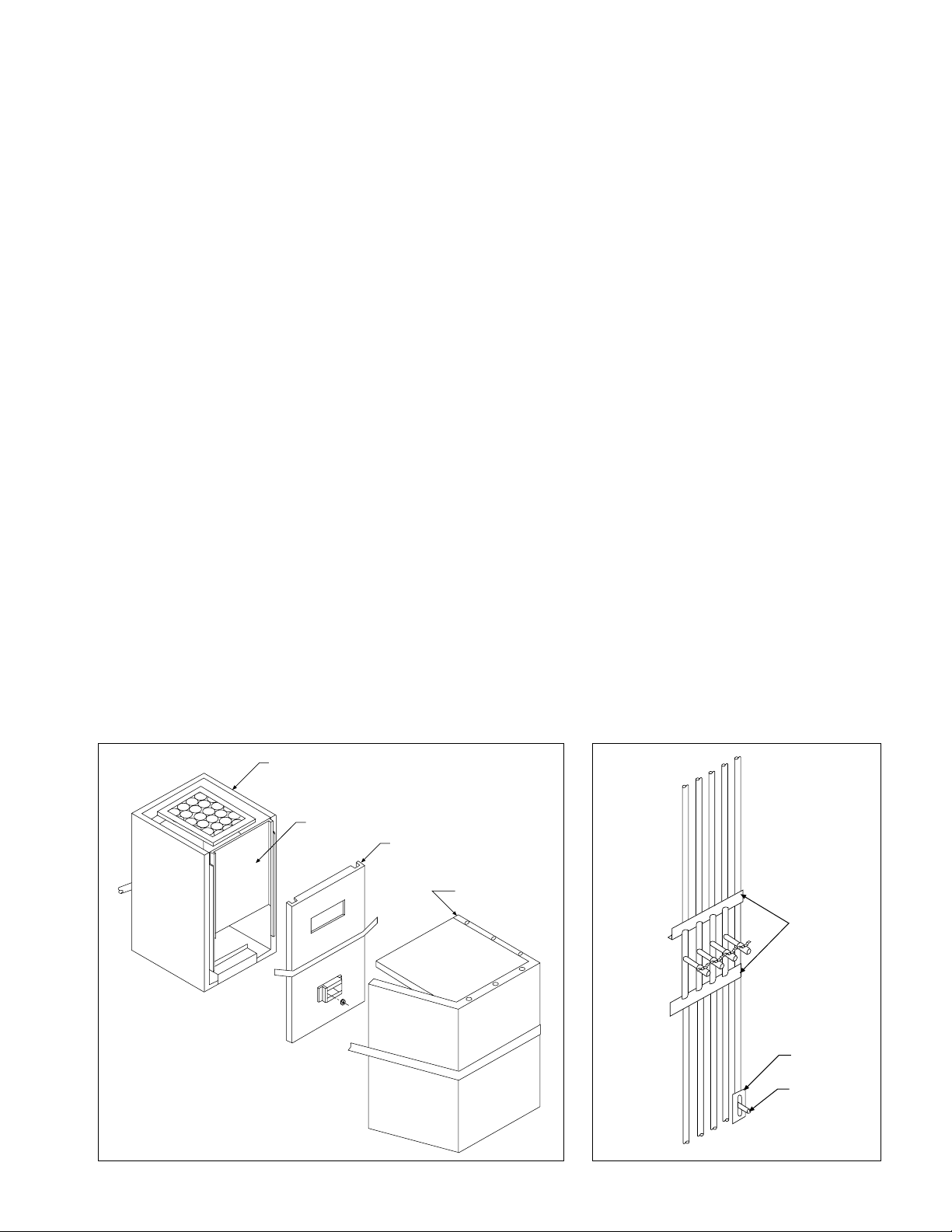
Unit Installation
Riser
Blockoffs
Drain Blockoff
Drain Riser
1. The KZZ HiLine fan-coil units have been received with
the top plenum and plenum front cover not assembled
to the lower cabinet (see Figure 3).
2. Care should be taken when removing the top plenum
from the lower cabinet so as not to tear the fiberglass
insulation.
3. Remove the plenum front panel from the lower cabinet.
4. The fasteners for assembling the unit, the riser blockoffs,
and sight baffle (if required) are located in the base of the
lower cabinet. The filter is located above the coil. Remove these parts from the unit. Remove the valve package supports.
5. For ease of installation, bend out the tabs that support
the top plenum to the lower cabinet (see Figure 5).
6. Place the riser blockoffs over the riser stub-outs (see
Figure 4).
7. Remove the appropriate riser and drain knockouts in the
lower cabinet (see Figure 5).
8. Slit the fiberglass insulation so that the riser valves can
be pushed through and into the unit.
9. Position the lower cabinet to the risers. The horizontal
stub-outs should be centered in the opening in the
cabinet. This is important to allow for riser expansion
and contraction of plus or minus one inch.
10. Solder connections if sweat valves have been supplied.
11. Attach plastic drain hose to drain line. Be sure hose
clamp is properly installed.
12. With the unit in the final location, check level to insure
proper condensate drainage and operation.
13. Fasten the top panel of the plenum by installing the three
sheet metal screws “A” (see Figure 6).
14. Install the sight baffle (if required) to the top as shown in
Figure 6.
15. Place the top plenum on the lower cabinet (see Figure 6).
The top plenum can be installed so that the discharge
opening is facing to the left, the right, or to the front.
Knockouts are provided for additional discharge arrangements. If plenum is to be rotated to the left or right,
the thermostat box can be moved to an alternate location by removing the optional cover plate. When the
thermostat is moved to the alternate location the cover
plate must be insulated and reinstalled in the previous
location. Determine the correct discharge before installing the plenum to the lower cabinet.
Although the plenum may be rotated 90° in either
direction, the thermostat box and heat baffle must
always be located above the return air grille on units with
electric heat.
16. Fasten the top plenum to the lower cabinet with sheet
metal screws (see Figure 6).
17. Before fastening the plenum front panel to the plenum
wrap, snap the nylon electrical receptacle into the square
hole into the back of the thermostat box (see Figure 7).
18. Attach the plenum front panel to the plenum wrap with
sheet metal screws enclosed.
19. The thermostat box has been installed in the plenum
front panel in the position that will allow plasterboard to
be attached directly to the unit. If the installation requires
that the wall be furred out away from the unit, the box can
be adjusted out 3
7
⁄8" (98 mm) by removing the four
screws “A” (see Figure 8) and pulling the box out. Align
with holes “C”. Replace screws “A”. If a dimension other
than the 3
7
⁄8" (98 mm) or 3⁄8" (10 mm) is required, this can
be accomplished by using the angle bracket as a template and drilling .149" (4 mm) diameter holes in the box
at the desired depth.
20. When the plasterboard or other wall material does not fit
flat against the face of the unit, extension sleeves must
Figure 3. Unit preparation for field assembly Figure 4. Riser blockoff placement
Lower Cabinet
Serial Plate
Top Front Panel
Top Plenum
Page 3
Page 4

be furnished by the contractor for both the return and
supply air openings.
21. Wire in accordance with local codes or the National
Electric Code, whichever is applicable. Provide branch
circuit overcurrent protection and disconnect means.
The complete system wiring diagram is located on the
front access cover. Bring electrical wiring through the
side of the cabinet into the wiring box located on the
right-hand side of the cabinet (see Figure 7). Two
7
⁄8" (22
mm) diameter knockouts are provided.
22. The return air bulb on the thermostat must be strung
through the hole in the back of the thermostat box and
down through the hole in the fan deck support angle and
attached to the bulb clip below the fan deck (see Figure
7).
23. Rotate the fan wheel by hand to make sure wheel is free.
24. Vent the coils. Vent is accessible from return air opening.
25. If ducts are being added, be sure the resistance is within
the limits of the external static pressures shown in the
catalog for the particular unit being installed. The ducts
should be designed for velocities in accordance with the
connection between the unit and ductwork. Ductwork
should be installed in accordance with NFPA 90A and
NFPA 90B.
26. When furring in units, make sure that no screws (other
than grille or plaster frame attaching screws) or nails
penetrate the unit cabinet. Grille or plaster frame attaching screws should never penetrate the cabinet more
than two inches.
27. When installing the grille panel without a plaster frame,
use it as a template to drill pilot holes into the wall or unit
for attaching screws (see Figure 11).
When a plaster frame is ordered, it should be attached on the opening over the top of the plasterboard.
Use the plaster frame as a template to drill pilot holes
into the wall or unit for the attaching screws (see Figure
12).
In order for the grille panel to fit the plaster frame
properly, the plaster frame must be mounted with the
corners square. When the plaster frame has been
mounted to the unit, attach the two retaining clips
(supplied with the plastic frame) to the plaster frame
adjacent to the lower attaching screws (see Figure 13).
methods outlined in the ASHRAE Guidebooks. It is
recommended that airborne noise be controlled with
sound attenuating materials and by installing flexible
Figure 5. Riser knockout locations Figure 6. Installation of top plenum
Riser
Knockouts
(All Sides)
Drain Knockout
(All Sides)
Front Access Cover
Riser
Knockouts
(All Sides)
“A”
Plenum Wrap
Optional Sight Baffle
Plenum/
Front
Panel
Alternate Thermostat
Location (For Hydronic
Units Only)
Front Access
Panel
Page 4
Support
Tabs
Drain Knockout
(All Sides)
Page 5

Figure 7. Thermostat installation
Capillary
Tube For
Return Air
Bulb
Return
Air Bulb
Receptacle
Quick-Connect Plug
Unit Mounted
Thermostat
B 41⁄2" (114 mm)
C 1415⁄16" (379 mm)
Field Wiring
Box
Coil
Drain Pan
& Fan Deck
20"
(508 mm)
11/32"
(9 mm)
3/8" +
(10 mm +)
(51 mm)
35"
(889 mm)
Thermostat Box
Access Panel
7/8" (22 mm)
Knockouts
2"
42-7/8"
(1089 mm)
Discharge
Opening
2"
(51 mm)
60"
(1524 mm)
20"
(508 mm)
(25 mm)
B
B
C
5" (127 mm)
1"
86"
(2184 mm)
104”
(2641.6 mm)
Drain Line
Return Air
Opening
19"
(483 mm)
1" (25 mm)
Page 5
Page 6

Figure 8. Thermostat electrical box
“A”
(Both
Sides)
3/8" (10 mm)
3-7/8"
(98mm)
Figure 9. Field wiring box for units with line voltage control Figure 10. Field wiring for units with low voltage control
systems systems
Wiring
Box
Cover
Wiring Box
Pigtails For
Field Wiring
Terminal
Block
Wiring
Box
Cover
Wiring Box
Pigtails For
Field Wiring
Low Voltage
Compartment
Terminal
Block
Page 6
Page 7

Figure 11. Grille panel without plaster frame, plan view Figure 12. Grille panel with plaster frame, plan view
1/2" (13 mm)
(14 mm)
Grille
Panel
4 Screws
Provided
9/16"
3/8"
(10 mm)
(10 mm)
Wall
1/2" (13 mm)
Cabinet
3/8"
Figure 13. Installation of grille panel with plaster frame
Wall
Plaster
Frame
Grille
Panel
15/32"
(12 mm)
Wall
Cabinet
Four (4) Screws for
attaching the Plaster
Frame are provided.
Wall
Retaining
Clip
Retaining Clip
Start-up
1. After the unit is furred in, but prior to unit start-up, make
sure no foreign material remains in the unit, paying particular attention to the drain pan and drain line. Blockage
of the drain line will result in water overflow of the drain
pan.
2. Open supply and return water service valves.
3. If unit does not have the automatic flow control option,
balance water flow rate with hand valve on return line.
4. Replace front access cover (see Figure 5).
5. Put filter into position.
6. Install return air grille.
Retaining
Pin
Grille
Panel
Grille Panel
Plaster
Frame
7. All windows and doors should be in and closed before
starting up the unit.
8. Switch unit to “on” and check for proper operation of fan,
fan speed switch and thermostat.
9. When there is a high amount of moisture in the air, the
initial pulldown should be very gradual (high fan speed for
maximum airflow with reduced gpm and elevated chilled
water temperature for reduced capacity). Outside air
supply and toilet exhaust systems should not be operated
until the gradual pulldown has been completed. If these
steps are taken, the possibility of the unit sweating will be
reduced.
Page 7
Page 8

Maintenance
1. Filters must be clean to obtain maximum performance.
They should be inspected every three or four months
under normal operating conditions and be replaced when
necessary. Units should never be run without a filter.
2. In areas where airborne bacteria produce slime in the
drain pan, it may be necessary to treat chemically to
minimize the problem. Contact your local McQuay representative or one of the many companies dealing with
water conditioning.
3. The condensate drain pan can pick up lint and dirt,
especially with dirty filters. Inspect twice a year to avoid
the possibility of overflow.
Service
1. If fan motor service is required on the S03 or the S04, the
fan motor can be removed through the return air opening
as follows:
a. Shut off electrical power to unit.
b. Remove return air grille panel.
c. Remove front access cover (see Figure 6).
d. Disconnect the fan motor leads at the wiring box.
e. Remove the bottom half of the fan housing by taking
out the two screws on the housing.
f. Remove the clips that hold the motor to the motor
base.
g. Remove the motor.
h. Fan wheel is pressed on motor shaft; pull to remove.
i. Reverse process to reassemble.
2. If fan motor service is required on the S06 or S08, the fan
and motor can be removed through the return air opening
as follows:
a. Shut off electrical power to unit.
b. Remove return air grille panel.
c. Remove front access cover (see Figure 6).
d. Disconnect the fan motor leads at the wiring box.
e. Remove the screws that hold the inlet ring to the fan
housing.
f. Remove the fan wheel, motor, and inlet ring assembly
from the fan housing.
g. Loosen fan wheel setscrew.
h. Remove the three screws holding the motor to the inlet
ring.
i. Service can now be performed.
j. Reverse process to reassemble.
4. The fan motor has been oiled at the factory. It is not
necessary to oil the first six months when under continuous operation. Oil every six months with one teaspoon or
5 cc per bearing of SAE No. 20 nondetergent oil. Do not
overlubricate.
5. The coil must be clean to obtain maximum performance.
Check once a year under normal operating conditions and
if dirty brush or vacuum clean. Care must be taken not to
damage the aluminum fins while cleaning. Caution: Fin
edges are sharp.
3. The McQuay electric heat elements, if furnished, are
designed with a high limit control set to trip out when the
cabinet temperatures reach and excessive temperature
and automatically rest when the cabinet temperatures
return to normal.
If the high limit opens the circuit, the unit is not
performing properly and should be checked to find the
cause. Some probable causes would not be enough air
over the heater due to dirty filter, fan motor not operating,
dirty coil, fan wheel loose on the motor shaft, or loose
electrical connections.
4. If the electrical heater should require service, it can be
done in the following manner:
a. Shut off electrical power to the unit. Caution: There
may be more than one power source on the unit.
b. Remove the return air grille and front access cover.
c. Remove the electric heater junction box cover.
d. The high limit control can be replaced without remov-
ing the element from the unit. It is done by removing the
nut on the appropriate terminal post and lifting the
defective part out.
e. The entire element can be removed by disconnecting
the wires form the terminal posts and removing the
screws in the back of the junction box that hold the
heater to the support bracket. Slide the heater out and
replace.
f. The electric heater contactor is located in the field
wiring box (see Figures 9 and 10).
Replacement Parts
When writing for service or replacement parts, direct your
letter to McQuayService. Always provide a complete de-
AAF-McQuay Incorporated
4900 Technology Park Boulevard, Auburn, NY 13021-9030 USA (315) 253-2771
Printed on recycled paper containing at least 10% post-consumer recycled material.
scription of the service part, part number (if known), plus
complete serial and model number of unit involved.
 Loading...