

Page 1

CEILING CASSETTE
SPLIT TYPE AIR CONDITIONER
(A Series)
INSTALLATION MANUAL
Group: CEILING CASSETTE
Part Number: A08019025503
Date: MAY 2001
IM-CKA-0501-McQuay
© 2001 McQuay International
Page 2

Page 3
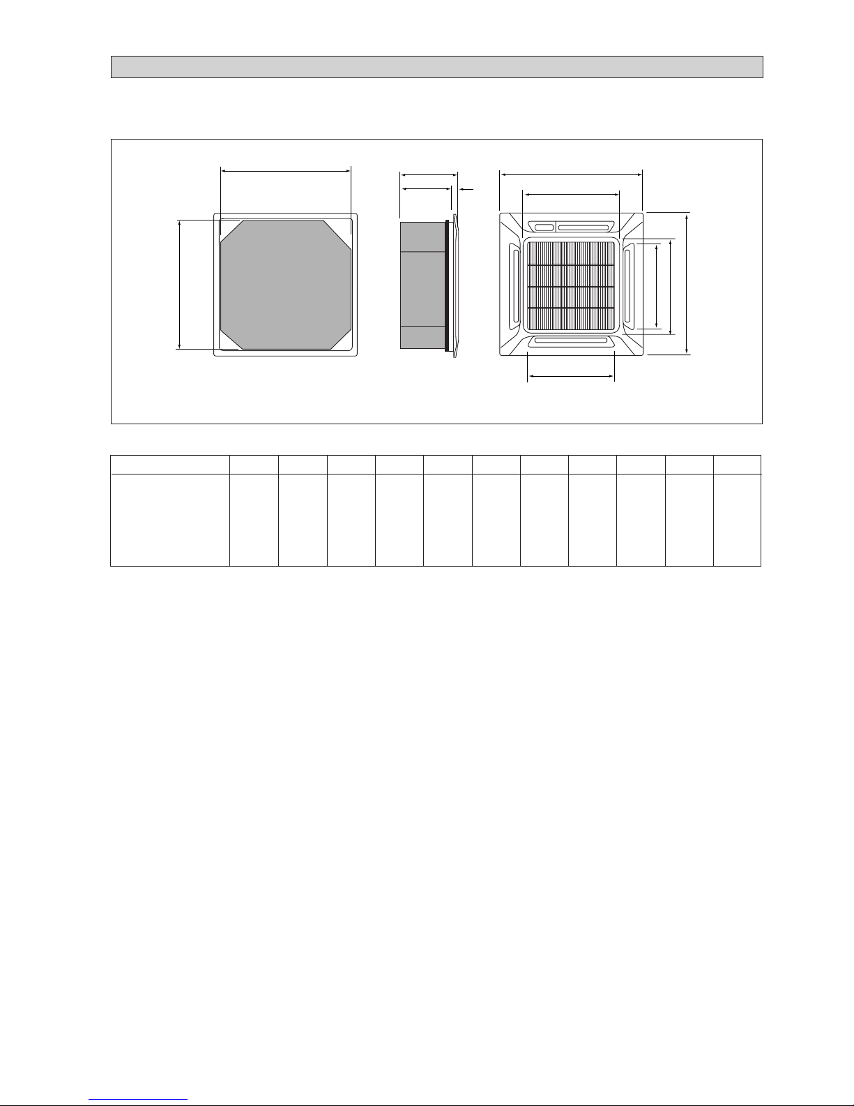
OUTLINE AND DIMENSIONS
Indoor Unit (CKA Series)
• (With Wireless Remote Control & With Wired Remote Control)
All dimensions are in mm / (in)
i
A
B
C
DE
F
H
M
J
I
G
MODEL A B C D E F G H I J K
20A / 20AR
25A / 25AR
30A / 30AR
820 820 363 335 28 930 930 642 622 555 555
40A / 40AR
(32,2) (32,2) (14,3) (13,2) (1,1) (36,6) (36,6) (25,2) (24,5) (21,9) (21,9)
50A / 50AR
Page 4
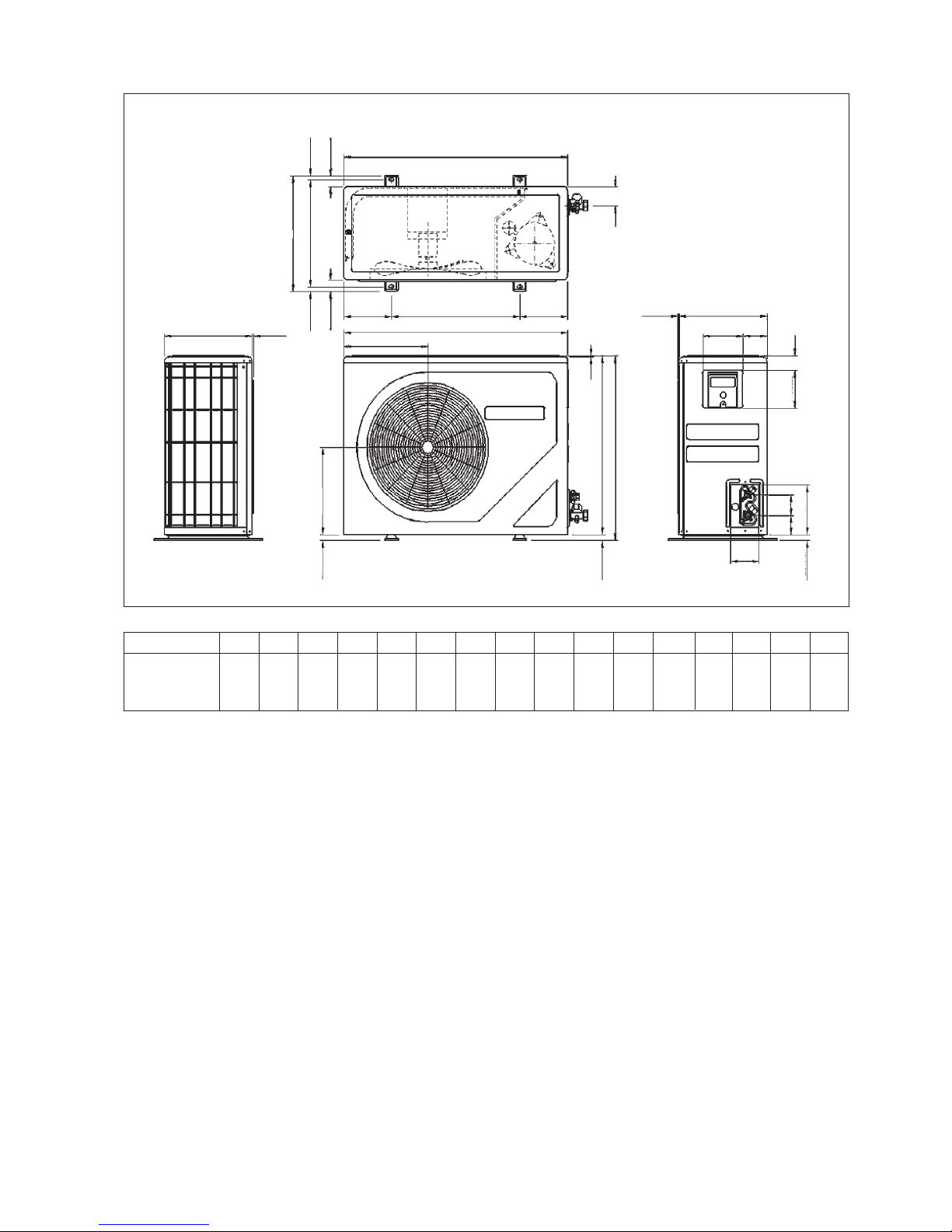
Outdoor Unit (SL - B Series)
All dimensions are in mm / (in)
Dimension A B C D E F G H J K L M N P Q R
20B / 20BR
840 646 330 297 309 626 41 85 75 177 106 408 378 124 592 78,5
25B / 25BR
(33,1) (25,4) (13,0) (11,7) (12,2) (24,6) (1,6) (3,3) (3,0) (7,0) (4,2) (16,1) (14,9) (4,9) (23,3) (3,1)
30B / 30BR
15 (0,6)
39 (1,5)
840 (33,1)
124 (4,9)
840 (33,1)
297 (11,7)
15 (0,6)
39 (1,5)
5 (0,2)
20 (0,8)
20 (0,8)
2,5 (0,1)
5 (0,2)
160 (6,3)
141
(5,6)
(2,6)
65
20 (0,8)
78,5 (3,1)
124 (4,9)592 (23,3)
378 (14,9)
408 (16,1)
330 (13,0)
330 (13,0)
85
(3,3)
41
(1,6)
(3,0)
75
177 (7,0)
106
(4,2)
626 (24,6)
646 (25,4)
309 (12,2)
ii
Page 5

iii
B
A
Q
R
ST
DO
KLL
CN
P
M
N
FE
C
GH
IJ
FOR SL25C/CR
ONLY
Dimension A B C D E F G H I J K L M N O
20C/CR 855 628 328 508 181 44 93 149 101 113 603 126 164 17 49
(33,7) (24,7) (12,9) (20,0) (7,1) (1,7) (3,7) (5,9) (4,0) (4,4) (23,7) (5,0) (6,4) (0,7) (1,9)
25C/CR 855 730 328 513 182 44 93 149 101 113 603 126 164 17 47
28C/CR (33,7) (28,7) (12,9) (20,2) (7,2) (1,7) (3,7) (5,9) (4,0) (4,4) (23,7) (5,0) (6,4) (0,7) (1,9)
Dimension P Q R S T
20C/CR 32 3 23 73 75
(1,3) (0,1) (0,9) (2,9) (3,0)
25C/CR 32 3 23 73 75
28C/CR (1,3) (0,1) (0,9) (2,9) (3,0)
All dimensions are in mm / (in)
Outdoor Unit : SL20C / 25C / 28C & CR
Outdoor Unit : SL30C / 40C / 50C & CR
141,5 (5,6) 746,5 (29,4)
1030,0 (40,6)
20,0
(0,8)
448,0
(17,6)
850,0 (33,5)
25,0 (1,0)
50,0
(2,0)
85,0
(3,3)
400,0 (15,7)
320,0 (12,6)
40,0
(1,6)
40,0
(1,6)
141,5 (5,6)
20,0
(0,8)
All dimensions are in mm / (in)
Page 6

iv
This product is subjected to Waste of Electrical and Electronic Equipment Regulations (WEE
E
Regulations). The waste product shall be separately collected by specific collection and treatment centre
.
P
lease refer to local authorithy for these centres. This is only applicable to European Union countries
.
Ce produit est soumis
à
la r
ééé
é
lectriques e
t
ййкйй
ééé
é
tre ces centres. Ceci
est uniquement applicable aux pays de l'Union Euro
p
é
enne
.
Questo prodottoè soggetto alle disposizioni RAEE (Rifiuti di apparecchiature elettriche ed elettroniche)
.
à
à
locali. Questa disposizione
è
valida solamente i paes
i
dell
U.E.
é
ctrico y Electrnico en materia d
e
fico
de colecc
i
solamente aplicable a los pases de la Un
i
n
Europea
.
Dieses Produkt unterliegt den Bestimmungen zur Entsorgung von elektrischen und elektronische
n
er
tes
ü
ll bei Ihrer
ü
ndiges Abfall-Amt. Dieser
Hinweis gilt nur f
ischen Union
.
Процес
с
у
тилизациианногопродуктарегулируетсяправиламип
о
у
тилизаци
и
отходо
в
(WEEE Regulations).
т
и
правил
а
Европейског
о
NOTICE
Scharfe Kanten und Wärmetauscherflächen stellen eine Gefahrenquelle dar. Jeglicher
Kontakt mit diesen Stellen ist zu vermeiden.! Vorsicht
! Cautela
Per preservarsi da eventuali ferite, evitare di toccare gli spigoli afilati e la superficie dei
serpentini.
! Cuidado
Los Bordes afilados y la superficie del serpentín pueden producir lesiones. Evite tocarlos.
! Осторожно
Острые края и поверхности змеевиков являются потенциальными
местами нанесения травм. Остерегайтесь контакта с этими местами.
Sharp edges and coil surfaces are potential locations which may cause injury hazards. Avoid
from being in contact with these places.
! Caution
! Avertissement
Les bords coupants et les surfaces du refroidisseur tuulaire présentent un risque
de blessure. Mieux vaut éviter le contact avec ces endroits.
Page 7

1-1
English
This manual provides the procedures of installation to ensur e a safe and good standard of operation for the air
conditioner unit.
Special adjustment may be necessary to suit local requirements.
Before using your air conditioner, please read this instruction manual car efully and keep it for futur e refer ence.
INST ALLA TION MANUAL
CEILING CASSETTE SPLIT TYPE AIR CONDITIONER
MODEL
COOLING ONLY HEAT PUMP
Part No.:A08019025503
IM-CKA-0501(2)-McQuay
CK20AR / MCK20AR
SL20CR / MLC20CR
4SL20BR / M4LC20BR
5CK20AR / M5CK20AR
5SL20CR / M5LC20CR
CK25AR / MCK25AR
SL25CR / MLC25CR
4SL25BR / M4LC25BR
5CK25AR / M5CK25AR
5SL25CR / M5LC25CR
CK30AR / MCK30AR
SL28CR / MLC28CR
SL30CR / MLC30CR
4SL30CR / M4LC40CR
5CK30AR / M5CK30AR
5SL28CR / M5LC28CR
5SL30CR / M5LC35CR
CK40AR / MCK40AR
SL40CR / MLC40CR
4SL40CR / M4LC40CR
5CK40AR / M5CK40AR
5SL35CR / M5LC35CR
5SL40CR / M5LC50CR
CK50AR / MCK50AR
SL50CR / MLC50CR
4SL50CR / M4LC50CR
5CK50AR / M5CK50AR
5SL50CR / M5LC50AR
CK20A / MCK20A
SL20C / MLC20C
4SL20B / M4LC20B
5CK20A / M5CK20A
5SL20C / M5LC20C
CK25A / MCK25A
SL25C / MLC25C
4SL25B / M4LC25B
5CK25A / M5CK25A
5SL25C / M5LC25C
CK30A / MCK30A
SL28C / MLC28C
SL30C / MLC30C
4SL30C / M4LC40C
5CK30A / M5CK30A
5SL28C / M5LC28C
5SL30C / M5LC35C
CK40A / MCK40A
SL40C / MLC40C
4SL40C / M4LC40C
5CK40A / M5CK40A
5SL35C / M5LC35C
5SL40C / M5LC40C
CK50A / MCK50A
SL50C / MLC50C
4SL50C / M4LC50C
5CK50A / M5CK50A
5SL50C / M5LC50C
Page 8

1-2
CONTENTS
- Outline And Dimensions page i – iv
- Safety Precautions page 2
- Installation Diagram page 3
- Installation Of The Indoor Unit page 4
- Installation Of The Outdoor Unit page 6
- Refrigerant Piping Work page 7
- Electrical Wiring Connection page 8
-
Special Precautions When Dealing With R410A Unit
page 11
-
Special Precautions When Dealing With R407C Unit
page 11
- Vacuuming And Charging page 11
SAFETY PRECAUTIONS
Before installing the air conditioner unit, please read the following safety precautions carefully.
! W arning
• Installation and maintenance should be performed by qualified persons who are familiar with local code and
regulation, and experienced with this type of appliance.
• All field wiring must be installed in accordance with the national wiring regulation.
• Ensure that the rated voltage of the unit corresponds to that of the name plate before commencing wiring work
according to the wiring diagram.
• The unit must be GROUNDED to prevent possible hazard due to insulation failure.
• All electrical wiring must not touch the refrigerant piping or any moving parts of the fan motors.
• Confirm that the unit has been switched OFF before installing or servicing the unit.
- Special Precautions When Charging Unit With
Copeland Scroll Compressors page 12
- Accessory Parts page 13
- Indicator Lights page 13
- Overall Checking page 14
- Standard Operation Conditions page 15
- Auto Random Re-start Function page 15
- Service And Maintenance page 15
- Troubleshooting page 16
- Phase Sequencer (Optional) page 16
! Caution
Please take note of the following important points when installing.
• Do not install the unit where leakage of flammable gas may occur.
If gas leaks and accumulates around the unit, it may cause fire ignition.
• Ensure that the drainage piping is connected properly.
If the drainage piping is not connected properly, it may cause water leakage which will dampen the
furniture.
• Do not overcharge the unit.
This unit is factory pre-charged. Overcharge will cause over-current or damage to the compressor.
• Ensure that the units panel is closed after service or installation.
Unsecured panels will cause the unit to operate noisily.
Page 9

1-3
English
Indoor unit
Outdoor unit
Drain Hose
Front Panel
Air Filter
(behind the grille)
Air Discharge Louver
IR Receiver
LED Light
Air Intake Grille
Refrigerant Piping
Air Intake
Air Discharge
Wireless Remote Control
Air Discharge Louver
Remote Control
INST ALLA TION DIAGRAM
Outdoor unit
Drain Hose
Front Panel
Air Filter
(behind the grille)
Air Discharge Louver
Air Intake Grille
Air Discharge Louver
Refrigerant Piping
Air Intake
Air Discharge
Remote Control
Wired Remote Control
Air Intake
Air Intake
Indoor unit
Page 10
1-4
INSTALLATION OF THE INDOOR UNIT
Preliminary Site Survey
• Electrical supply and installation is to conform to local authority's (e.g. National Electrical Board) codes and regulations.
• Voltage supply fluctuation must not exceed +10% of rated voltage. Electricity supply lines must be independent of welding
transformers which can cause high supply fluctuation.
• Ensure that the location is convenient for wiring, piping and drainage.
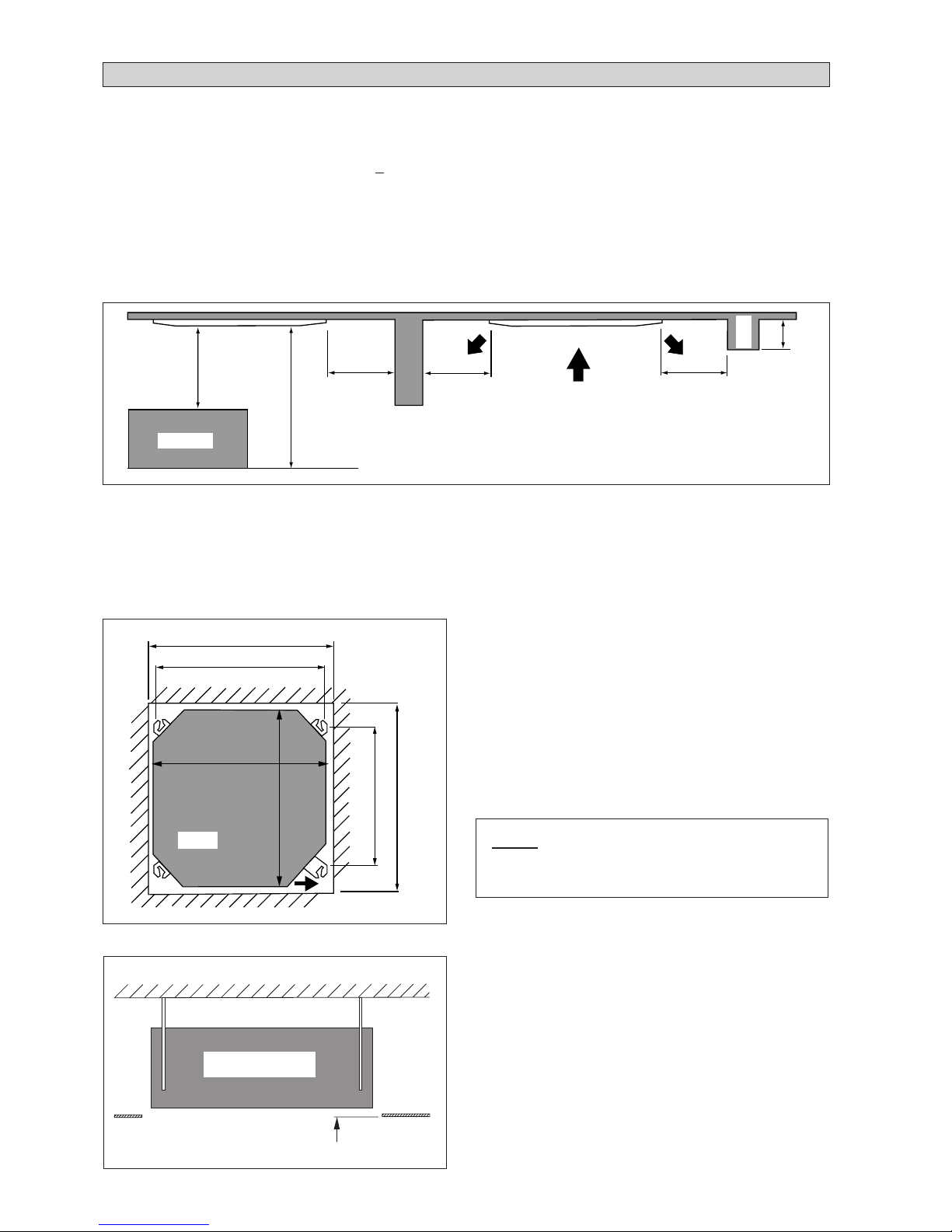
• The indoor unit must be installed in such that is free from any obstacles in path of cool air discharge and warm air return,
and must allow spreading of air throughout the room (near the center of the room).
• Must be provide clearance for the indoor unit from the wall and obstacles as shown in the figure.
• The installation place must be strong enough to support a load 4 times the indoor unit weight to avoid amplifying noise and
vibration.
• The installation place (hanging ceiling surface) must be assuring levelness and the height in the ceiling is 350mm or more.
• The indoor unit must be away from heat and steam sources (avoid installing it near an entrance).
Unit Installation
• Measure and mark the position for the hanging rod. Drill
the hole for the angle nut on the ceiling and fix the hanging
rod.
• The installation template is extended according to
temperature and humidity. Check on dimensions in use.
• The dimensions of the installation template are the same
as those of the ceiling opening dimensions.
• Before ceiling laminating work is completed, be sure to
fit the installation template to the indoor unit.
NOTE
Be sure to discuss the ceiling drilling work with the
installers concerned.
• Confirm the pitch of the hanging rod is 790mm × 620.5mm
sharp.
• Hold the unit and hang it on the hanging rod with the nut
and washer.
• Adjust the unit height to 35.0 mm between the indoor unit
bottom surface and the ceiling surface.
• Confirm with a level gauge that the unit is installed
horizontally and tighten the nut and bolt to prevent unit
falling and vibration.
• Open the ceiling board along the outer edge of the paper
installation template.
Unit Hanging
Min. 0.5 m Min. 0.5 m Min. 0.5 m
Max. 0.3 m
Max. 3.0 m
Min. 1.0 m
Floor
Obstacle
Beam
35.0 mm
Ceiling
Board
Indoor Unit
890.0 mm (Ceiling board opening)
790.0 mm (Hanging rod)
Unit size 820.0 mm
890.0 mm (Ceiling board opening)
620.5 mm (Hanging rod)
Unit size 820.0mm
Unit
Piping Direction
Page 11
1-5
English
Main Drain Pipe
Feed Water
Flexible Drain Hose
Drain Test
NOTE
This Indoor Unit uses a drain pump for condensed water drainage. Install the unit horizontally to prevent water
leakage or condensation around the air outlet.
Indoor Unit
Pipe Clamp
Good
Bad
Drain Piping W ork
• Drain pipe must be in downward gradient for smooth
drainage.
• A void installing the drain pipe in up and down slope to
prevent reversed water flow.
• During the drain pipe connection, be careful not to exert
extra force on the drain connector at indoor unit.
• The outside diameter of the drain connection at the
flexible drain hose is 20mm.
• Be sure to execute heat insulation (polyethylene foam
with thickness more than 8.0mm) on the drain piping to
avoid the condensed water dripping inside the room.
• Connect the main drain pipe to the flexible drain hose.
• Feed water from flexible drain hose to check the piping
for leakage.
• When the test is completed, connect the flexible drain
hose to the drain connector on the indoor unit.
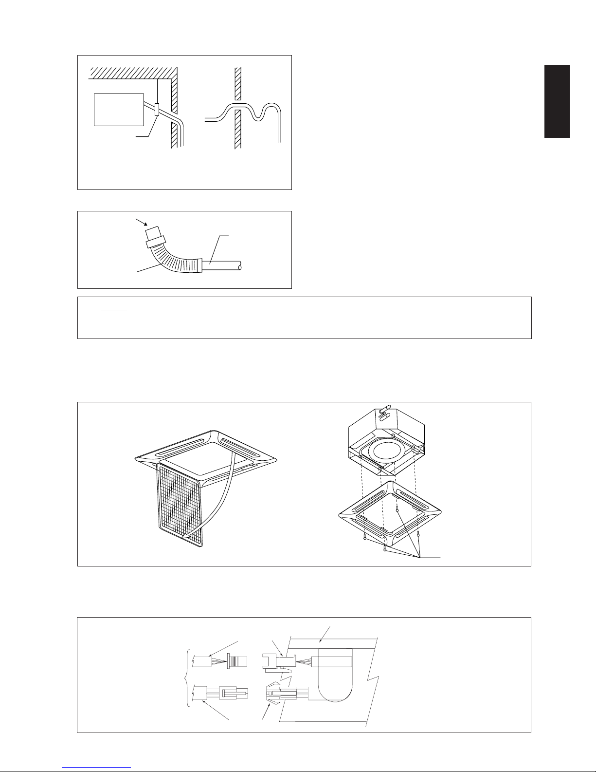
• The front panel can only be fitted in one direction, follow the piping direction. (Follow piping arrow sticker on front
panel)
• Be sure to remove the installation template before installing the front panel.
Panel Installation
Open
Screw
• Open the air intake grille by pulling back the catchers and removing it together with filter from panel.
• Install the front frame panel onto the indoor unit by 4 screws and tighten it completely to prevent cool air leakage.
• Connect the LED wire and air swing wire to the indoor unit.
From
Front
Panel
LED Wire
Air Swing Wire
Control Box
Page 12

1-6
Indoor Unit
Cool
Air
Ceiling Board
Panel
Air Leak
Good Installation
Bad Installation
NOTE
Install the front frame panel firmly to prevent cool air leakage which will cause condensation and water dripping.
Cool
Air
Air Leak
Ceiling Board
Panel
Air intake grille installation
• Before installing the air intake grille, be sure to fix the ionizer
filter to the air filter.
• Install the air intake grille together with the air filter to the
front panel.
• The grille can be fit in any direction, when selecting direction,
the ceiling design and grille operability should be considered.
• If the unit comes with ionizer filter (optional item), make
sure to fix the ionizer filter to the air filter before installing
the air intake grille.
• Fix the ionizer filter to the air filter with the black side on top
and white side at bottom.
• Carefully clip on the ionizer filter frame.
Frame
(Optional Item)
Ionizer Filter
(Optional Item)
Filter
(Standard)
INSTALLATION OF THE OUTDOOR UNIT
Preliminary site survey
• A place protected from rain, direct sunlight and well-ventilated wherever practicable.
• A place capable of bearing the weight of the outdoor unit and isolating noise and vibration.
• A place where there are no obstruction of air flow into or out the unit.
• Do not put any object which may become obstacle for the air flow into or out the outdoor unit.
• The location must not be susceptible to high concentration dust, oil, salt or sulfide gas.
SL series A B C D
Min. distance (mm) 300 1000 300 500
Outdoor unit installation
• Install the outdoor unit firmly and horizontally. Maintain a space clearance from the obstruction as shown in below for
servicing and air ventilation.
AB
C
D
Page 13

1-7
English
REFRIGERANT PIPING WORK
Refrigerant piping is important in particular. Refrigeration cycle of the split air conditioner is realized
by the perfect piping work.
Piping length and elevation
If the piping is too long, both the capacity and reliability of unit will drop. As the number of bends increase, resistance to
flow of refrigerant system increases, thus lowering cooling capacity and as a result the compressor may become defective.
Always choose the shortest path and follow the recommendation as tabulated below .
Piping Connection
• Do not use contaminated or damaged copper tubing. If any piping, evaporator or condenser had been exposed or had been
opened for 15 seconds or more, then vacuum and purge with field supplied refrigerant. Generally, do not remove plastic,
rubber plugs and brass nuts from the valves, fittings, tubing and coils until it is ready to connect suction or liquid line into
valves or fittings.
• If any brazing work is required, ensure that nitrogen gas is passed through coil and joints while the brazing work is being
done. This will eliminate soot formation on the inside wall of copper tubings.
• Cut the pipe stages by stages, advancing the blade of pipe cutter slowly. Extra force and a deep cut will cause more
distortion of pipe and therefore extra burr.
• Remove burrs from cut edges of pipes with a remover. This will avoid unevenness on the flare face which will cause gas
leak.
• Align the center of the piping and sufficiently tighten the flare nut with fingers. Finally, tighten the flare nut with torque
wrench until the wrench clicks.
• Be sure to execute heat insulation. (polyurethane form with thickness more than 15 mm)
• Except the outdoor unit which is pre-charge with refrigerant R22, the indoor unit and the refrigerant connection pipes must
be purged because the air that contain moisture remaining in the refrigerant cycle may cause malfunction to the compressor .
Model 4SL20B/BR SL20C/CR 4SL25B/BR SL25C/CR SL28C/30C/CR SL40C/50C/CR
Max. length (m) 15 15 35 35
Max. elevation (m) 8 8 10 10
Max. no. of bends 10 10 10 10
Liquid pipe size 1/4” 3/8” 3/8” 3/8”
Gas pipe size 5/8” 5/8” 5/8” 3/4”
Model 5SL20C/CR 5SL25C/CR 5SL28C/35C/40C/50C/CR
Max. length (m) 15 15 35
Max. elevation (m) 88 10
Max. no. of bends 10 10 10
Liquid pipe size 1/4” 1/4” 3/8”
Gas pipe size 1/2” 5/8” 5/8”
Page 14

1-8
ELECTRICAL WIRING CONNECTION
CK20A / CK25A & CK30A
Model Indoor CK20A CK25A CK30A
Outdoor SL20B/20C SL25B/25C SL28C/30C
Voltage range** 220-240V/1Ph/50Hz + ! or 208-230V/1Ph/60Hz+
!
Recommended fuse* (A) 16 20 25
Power supply cable size* (mm2) 2.5 2.5 4.0
Number of conductors 333
Interconnection cable size* (mm2) 2.5 2.5 2.5
Number of conductors 334
COMP
L
N
N
COMP
N
Interconnection Cable
Indoor Unit
Terminal
Block
Outdoor Unit
Terminal
Block
There must be a double pole switch with
minimum 3mm contact gap and fuse/circuit
breaker as recommended in the fixed
installation circuit.
CK20A / 25A <> SL20B / 25B / 20C / 25C
CK30A <> SL28C
Power
Supply
Cable
!
COMP
COMP
L
N
N
L
N
L
N
CK30A <> SL30C
Interconnection Cable
Indoor Unit
Terminal
Block
Outdoor Unit
Terminal
Block
There must be a double pole switch with minimum
3mm contact gap and fuse/circuit breaker as
recommended in the fixed installation circuit.
Power Supply Cable
!
Cooling Only
IMPORTANT: *These values are for information only . They should be checked and selected to comply with local and/or
national codes and regulations. They are also subject to the type of installation and size of conductors.
**The appropriate voltage range should be checked with label data on the unit. ETL listed is only applica-
ble to 60Hz power supply only.
Additional Charge (In gram)
The refrigerant is pre-charge in the outdoor unit, but additional charge of refrigerant after vacuuming is necessary. Follow
the recommendation as tabulated below .
Cooling Only (R22)
10m 15m 20m 25m 30m 35m
CK20A 40110----
CK25A 90 270 - - - -
CK30A/40A/50A 120 380 640 900 1150 1410
Cooling Only (R407C)
10m 15m 20m 25m 30m 35m
CK20A 40110----
CK25A 80 260 - - - -
CK30A/40A/50A 120 360 600 840 1090 1330
Cooling & Heatpump (R410A)
10m 15m 20m 25m 30m 35m
5CK20/25A/AR 30 100 - - - -
5CK30/40/50A/AR 80 230 390 550 710 870
Heatpump (R22)
10m 15m 20m 25m 30m 35m
CK20AR 40 110 - - - -
CK25AR 90 270 - - - -
CK30AR/40AR/50AR
90 280 460 650 830 1020
Heatpump (R407C)
10m 15m 20m 25m 30m 35m
CK20AR 40 110 - - - -
CK25AR 80 260 - - - -
CK30AR/40AR/50AR
80 260 430 610 780 960
Page 15

1-9
English
CK40A & CK50A
Model Indoor 5CK30/40A CK40A CK50A
Outdoor 5SL35C SL40C SL50C
Voltage range** 380-420V/3Ph /50Hz+ N+ ! or 208-230V/3Ph/60Hz+N+
!
Recommended fuse* (A) 10/20 16/25
Power supply cable size* (mm2) (50/60Hz) 1.5/2.5 2.5/4.0
Number of conductors 55
Interconnection cable size* (mm2) (50/60Hz) 1.5/1.5 1.5/1.5
Number of conductors 44
COMP
L
N
COMP
L
N
S
R
T
N
There must be a double pole switch with minimum
3mm contact gap and fuse/circuit breaker as
recommended in the fixed installation circuit.
CK40A / CK50A <> SL40C / SL50C
Indoor Unit
Terminal
Block
Interconnection Cable
Outdoor Unit
Terminal
Block
Power Supply Cable
!
CK20AR / CK25AR / CK30AR
Model Indoor CK20AR CK25AR CK30AR
Outdoor SL20BR/20CR SL25BR/25CR SL28CR/30CR
Voltage range** 220-240V/1Ph/50Hz+ ! or 208-230V/1Ph/60Hz+
!
Recommended fuse* (A) 16 20 25
Power supply cable size* (mm2) 2.5 2.5 4.0
Number of conductors 333
Interconnection cable size* (mm2) 2.5 2.5 2.5
Number of conductors 556
There must be a double pole switch with minimum
3mm contact gap and fuse/circuit breaker as
recommended in the fixed installation circuit.
4WV
OF
N1
L
N2
COMP
4V
OF
N
COMP
CK20AR / 25AR <>
SL20BR / 25BR
SL20CR / 25CR
Indoor Unit
Terminal
Block
Interconnection Cable
Outdoor Unit
Terminal
Block
Power
Supply
Cable
!
Outdoor Coil Sensor
Heat Pump
IMPORTANT : * These values are for information only . They should be checked and selected to comply with local and/or
national codes and regulations. They are also subject to the type of installation and size of conductors.
** The appropriate voltage range should be checked with label data on the unit.
Page 16

1-10
N
N
L
OF
A
4WV
COMP
N
OF
4WV
COMP
N
L
E
CK40AR & CK50AR
Model Indoor 5CK30/40AR CK40AR CK50AR
Outdoor 5SL35CR SL40CR SL50CR
Voltage range** 380-420V/3Ph/50Hz +N+ ! or 208-230V/3Ph/60Hz+N+
!
Recommended fuse* (A) 10/20 16/25
Power supply cable size* (mm2) 1.5/2.5 2.5/4.0
Number of conductors 55
Interconnection cable size* (mm2) 1.5/1.5 1.5/1.5
Number of conductors 77
A
4WV
OF
N
L
COMP
A
R
S
T
4WV
OF
N
N
L
COMP
CK40AR / CK50AR <> SL40CR / SL50CR
Outdoor Coil Sensor
Indoor Unit
Terminal
Block
Interconnection
Cable
Outdoor
Unit
Terminal
Power Supply
Cable
!
There must be a double pole switch with minimum
3mm contact gap and fuse/circuit breaker as
recommended in the fixed installation circuit.
CK30AR <> SL28CR
There must be a double pole switch with
minimum 3mm contact gap and fuse/circuit
breaker as recommended in the fixed
installation circuit.
Outdoor Coil Sensor
Indoor Unit
Terminal
Block
Interconnection Cable
Outdoor Unit
Terminal
Block
Power Supply Cable
!
CK30AR <> SL30CR
N
N
L
E
N
L
OF
A
4WV
COMP
N
L
N
L
OF
A
4WV
COMP
Interconnection Cable
Outdoor Coil Sensor
Indoor Unit
Terminal
Block
Outdoor Unit
Terminal
Block
There must be a double pole switch with minimum
3mm contact gap and fuse/circuit breaker as
recommended in the fixed installation circuit.
!
Page 17

1-11
English
SPECIAL PRECAUTIONS WHEN DEALING WITH R410A UNIT
R410A is a new HFC refrigerant which does not damage the
ozone layer. The working pressure of this new refrigerant is
1.6 times higher than conventional refrigerant (R22), thus
proper installation / servicing is essential.
• Never use refrigerant other than R410A in an air condi-
tioner which designed to operate with R410A.
• POE oil is used as lubricant for R410A compressor , which
is different from the mineral oil used for R22 compressor .
During installation or servicing, extra precaution must be
taken not to expose the R410A system too long to moist
air. Residual POE oil in the piping and components can
absorb moisture from the air.
• To prevent mischarging, the diameter of the service port
on the flare valve is different from that of R22.
SPECIAL PRECAUTIONS WHEN DEALING WITH R407C UNIT
• R407C is a zeotropic refrigerant mixture which has zero
ozone depletion potential and thus conformed to the
Montreal Protocol regulation. It requires Polyol ester oil
(POE) oil for its compressor's lubricant. Its refrigerant
capacity and performance are about the same as the refrigerant R22.
• POE oil is used as lubricant for R407C compressor , which
is different from the mineral oil used for R22 compressor .
During installation or servicing, extra precaution must be
taken not to expose the R407C system too long to moist
air. Residual POE oil in the piping and components can
absorb moisture from the air.
• Refrigerant R407C is more easily affected by dust of mois-
ture compared with R22, make sure to temporarily cover
the ends of the tubing prior to installation.
• Use tools and materials exclusively for refrigerant R410A.
Tools exclusively for R410A are manifold valve, char ging
hose, pressure gauge, gas leak detector, flare tools, torque
wrench, vacuum pump and refrigerant cylinder.
• As an R410A air conditioner incurs higher pressure than
R22 units, it is essential to choose the copper pipes correctly. Never use copper pipes thinner than 0.8mm even
though they are available in the market.
• If the refrigerant gas leakage occurs during installation /
servicing, be sure to ventilate fully. If the refrigerant gas
comes into contact with fire, a poisonous gas may occur.
• When installing or removing an air conditioner, do not
allow air or moisture to remain in the refrigerant cycle.
• No additional charge of compressor oil is permitted.
• No other refrigerant other than R407C.
• Tools specifically for R407C only (must not be used for
R22 or other refrigerant).
i) Manifold gauge and charging hose
ii) Gas leak detector
iii) Refrigerant cylinder/charging cylinder
iv) Vacuum pump c/w adapter
v) Flare tools
vi) Refrigerant recovery machine
• Filter-dryer must be installed along the liquid line for all
R407C air conditioners. This is to minimise the contamination of moisture and dirt in the refrigerant system. Filterdryer must be of molecular sieve type. For a heat-pump system, install a two-way flow filter dryer along the liquid line.
V ACUUMING AND CHARGING
Vacuuming is necessary to eliminate all moisture and air from the system. The series II Outdoor Unit is provided with flare
valve fittings.
Vacuuming
Before vacuuming, perform leak check for refrigeration
circuit. After the system piping are properly connected,
connect the flexible hoses to the correct charging nipples as
shown in the diagram. Ensure that flexible hose from charging
nipples are connected to the vacuum pump via standard
servicing valves and pressure gauges (gauge manifold).
Vacuum the air conditioner system to at least 500 microns
Hg. Do not start the unit when the system is engaged in
vacuuming.
Charging
Before charging, the vacuum must be held at 500 microns
Hg for at least 15 minutes, then break vacuum by charging
R-22 refrigerant. Operate the unit for 15 minutes and ensure
the refrigerant charges is of correct by monitoring running
current, gas and liquid line pressures. Suction and discharge
pipe pressure should be in the region of 75 psig and 275 psig
generally.
After ensuring the system is correctly charged, remove
flexible hose from charging nipples and replace caps.
Page 18

1-12
A
SPECIAL PRECAUTIONS WHEN CHARGING UNIT WITH
COPELAND SCROLL COMPRESSORS
These precautions are intended for use with Copeland Scroll compressors only with R22, R407C, R134A, R404A, R507 and
R410A refrigerants but are not applied to Copeland reciprocating compressors or competitive Scroll compressors.
Scroll compressors have a very high volumetric efficiency and quickly pump a deep vacuum if there is insufficient refrigerant
in the system or if refrigerant is added too slowly. Operation with low suction pressure will quickly lead to very high dischar ge
temperatures. While this process is happening, the scrolls are not being well lubricated – scrolls depend on the oil mist in the
refrigerant for lubrication. A lack of lubrication leads to high friction between the scroll flanks and tips and generates additional
heat. The combination of heat of compression and heat from increased friction is concentrated in a small localized discharge
area where temperatures can quickly rise to more than 300˚C. These extreme temperatures damage the Scroll spirals and the
orbiting Scroll bearing. This damage can occur in less than one minute especially on larger compressors. Failure may occur in
the first few hours or the damage done during field charging may show up some time later.
Other typical field charging problems include undercharging, overcharging, moisture or air in the system etc. In time each one
of these problems can cause compressor failure.
Minimal equipment is required for field charging. The minimum equipment required to do a satisfactory job is:-
Set of service gauges Vacuum gauge
Hoses Scales
Vacuum pump Thermometer
The proper refrigerant charge should follow the volume as recommended by manufacturer and recommendation should be
followed by the installer.
1. Charging procedures – Single phase compressors
Evacuate the system to 500 microns Hg. (67Pa). T o reduce evacuation time, use short, large diameter hoses and connect to
unrestricted service ports on the system. Quality of vacuum cannot be determined by time – a reliable vacuum gauge must
be used. (etc. electronic vacuum gauge)
Turn the refrigerant cylinder upside down, purge the charging hose and char ge liquid through the liquid line char ging port
until refrigerant no longer flows or until the correct charge has been weighed in. If additional charge is required start the
system and slowly bleed liquid into the suction side until the system is full.
Copeland recommends charging liquid in a CONTROLLED manner into the suction side until the system is full.
This recommendation does not hold true for reciprocating compressors where liquid charging into the suction side could
cause severe damage.
Carefully monitor the suction and discharge pressures – ensure that the suction pressure does not fall below 25 psig (1.7
bar) at any time during the charging process.
• Manifold Gauge will show cylinder pressure rather than suction pressure if the cylinder valve and Manifold
valve “A” are both open.
! Caution
There are many ways of charging liquid in a “controlled manner” into the suction
side:-
1. Use valve A on the manifold gauge set
2. Use the valve on the refrigerant cylinder
3. Charge through a Shredder valve
4. Use a hose with a Shredder valve depressor
5. Charge into the suction side at some distance from the compressor
6. All of the above
2. Charging procedures – Three phase compressors
The fundamental procedure is the same as for single phase models but the compressor can run in the wrong direction on
starting. If this happens reverse any two phases and start again. Short term reverse rotation will not damage the compressor.
All Specter compressors (Model: ZR90 to ZR19M) have internal discharge temperature protectors which are very effective
in preventing dangerously high discharge temperatures during charging. The protection module will trip and lock the
compressor out for 30 minutes. It is not normally necessary to wait 30 minutes for the module to reset. When the compressor
has cooled down the module can be reset by breaking the power supply to the control circuit. Very often the serviceman
does not understand why the module tripped and uses a jumper wire to bypass it. He continues to charge the system and
removes the jumper when charging is complete. The compressor may or may not run with the protector back in the circuit
but it is certain that the compressor has been damaged and premature failure is inevitable.
Page 19

1-13
English
Short Duct Specification
• The indoor unit is provided with air discharge and air intake “knock-out” hole for duct connection. However the connection of the short duct for air discharge is possible on only one side.
• The use of short duct for air discharge will improve airflow distribution if there is an obstruction (such as a lighting fixture)
or in a long, narrow room or an L-shaped room. It also use for air conditioning of two rooms simultaneously.
ACCESSORY PARTS
Possible Opening Dimension For Duct Connection
Air Discharge Knock Out Hole
Air Intake
Knock Out Hole
Possible Direction For Air Discharge And Air Intake
Air Intake
Air DischargeAir Discharge
Air Discharge Air Discharge
NOTE
• Avoid using the short duct on which the air dischar ge grille can be completely closed, to prevent evaporator freezing.
• In order to prevent condensation forming, be sure that there is sufficient thermal insulation and no leakage of cool
air when installing the short duct.
• Keep the introduction of fresh air intake within 20% of total air flow. Also provide a chamber and use a booster fan.
Sealing Material
• It is possible to seal one of the four air discharge outlet. (sealing two or more air discharge outlet could cause a malfunction)
• Remove the front panel and insert the sealing material into the air discharge outlet on the indoor unit to seal the air outlet.
• The sealing material is the same length as the longer air discharge outlet. If it is desired to seal the shorter air discharge
outlet, cut the sealing material to shorten it.
• Push the sealing material in about 10 mm beyond the bottom surface of the indoor unit so that it does not touch the air
louver. Be sure not to push the sealing material in any farther than about 10 mm.
10
50 50 50 50 50 10
207020109
119 90
Ø100
PCD Ø140
115 20 115
INDICA T OR LIGHTS
Remote Control
When there is infrared remote control operating signal, the signal receiver on indoor unit will make a <beep> for signal
acceptance confirmation.
Page 20

1-14
Operating State And Fault Table
Wireless Remote Control
Cooling Heat pump
POWER TIMER SLEEP POWER TIMER HEAT Operating / Faulty indication Action
/ / / / Power ON -
Room/Indoor/Outdoor (heat pump) Coil
Call Y our Dealer
Sensor Contact Loose/Short
Gas Leak Faulty/Compressor Overload Call Your Dealer
Condensate W ater Overflow Call Your Dealer
Outdoor Defrost (heat pump only) -
OVERALL CHECKING
• Ensure that :-
1) The unit has been mounted solidly and rigid in position.
2) Piping and connections are leak proof after charging.
3) Proper wiring has been installed.
• Drainage check – pour some water into the main drain pipe from the flexible drain hose.
• Test run
1) Conduct a test run after water drainage test and gas leakage test.
2) Check the following items :-
a. Is the electric plug firmly inserted into the socket ?
b. Is there any abnormal sound from the unit ?
c. Is there any abnormal vibration on the unit itself or piping ?
d. Is the drainage of water smooth ?
• Confirm that :
1) Condenser fan is running, with warm air blowing off the condensing unit.
2) Evaporator blower is running and discharge cool air.
3) The remote control incorporate a 3 minute delay in the circuit. Thus, it requires about 3 minutes before the outdoor
condensing unit can start up.
Cooling Heat pump
H M L C S T H M L C S T H Operating / Faulty Action
I E O O L I I E O O L I E indication
GDWOEMGDWOEMA
H LEEH LEET
PR PR
Room Sensor Contact Loose/Short Call Your Dealer
Indoor Coil Sensor Contact Loose/Short Call Your Dealer
Outdoor Coil Sensor Contact Loose/Short Call Your Dealer
Gas Leak Faulty Call Your Dealer
Compressor Overload Call Your Dealer
Condensate W ater Overflow Call Your Dealer
Outdoor Defrost (heat pump only) Call Your Dealer
Wired Remote Control
ON / ON or OFF BLINKING
Page 21

1-15
English
AUTO RANDOM RE-START FUNCTION
If there is a power cut when the unit is operating, it will automatically resume the same operating mode when the power is
restored. (Applicable only to units with this feature)
! Caution
Before turning off the power supply , set the remote controller's ON/OFF switch to the “OFF”
position to prevent the nuisance tripping of the unit.
If this is not done, the unit's fans will start turning automatically when power resumes,
posing a hazard to service personnel or the user.
SERVICE AND MAINTENANCE
Service parts
Indoor air filter
Indoor unit
! Caution
Do not operate any heating apparatus too close to the air conditioner unit. This may cause
the plastic panel to melt or deform as a result of the excessive heat.
Maintenance procedures
1. Remove any dust adhered on the filter by using a vacuum cleaner or
wash in lukewarm water (below 40ºC) with neutral cleaning detergent.
2. Rinse well and dry the filter before placing it back onto the unit.
3. Do not use gasoline, volatile substances or chemical to clean the filter.
1. Clean any dirt or dust on the grille or panel by wiping it using soft cloth
soaked in lukewarm water (below 40ºC) with neutral detergent solution.
2. Do not use gasoline, volatile substances or chemical to clean the indoor
unit.
Period
At least once every
2 weeks. More
frequently if
necessary.
At least once every
2 weeks. More
frequently if
necessary.
ST ANDARD OPERATION CONDITIONS
• Disconnect from the main power supply before servicing the air conditioner unit.
• DO NOT pull out the power cord when the power is ON. This may cause serious
electrical shocks which may result in fire hazards.
! W arning
Heat Pump Unit
Cooling unit
Temperature Ts °C / °F Th °C / °F
Minimum indoor
19.4 / 66.9 13.9 / 57.0
temperature
Maximum indoor
26.7 / 80.1 19.4 / 66.9
temperature
Minimum outdoor
19.4 / 66.9 13.9 / 57.0
temperature
Maximum outdoor
46 / 114.8 24 / 75.2
temperature
T s: Dry bulb temperature. Th: Wet bulb temperature.
Temperature Ts °C / °F Th °C / °F
Minimum indoor
10 / 50 –
temperature
Maximum indoor
26.7 / 80.1 –
temperature
Minimum outdoor
-8 / 17.6 -9 / 15.8
temperature
Maximum outdoor
24 / 75.2 18 / 64.4
temperature
Page 22

1-16
If any malfunction of the air conditioner unit is noted, immediately switch off the power supply to the unit.
Check the following fault conditions and causes for some simple troubleshooting tips.
TROUBLESHOOTING
Causes / Action
- Protection against frequent starting. Wait for 3 to 4
minutes for the compressor to start operating.
- Power failure, or the fuse need to be replaced.
- The power plug is disconnected.
- It is possible that your delay timer has been set incorrectly.
- If the fault persist after all these verifications, please
contact the air conditioner unit installer.
- The air filter is dirty.
- The doors or windows are open.
- The air suction and discharge are clogged.
- The regulated temperature is not high enough.
- Odors may be caused by cigarettes, smoke particles,
perfume etc. which might have adhered onto the coil.
- This is caused by air humidity after an extended long
period of operation.
- The set temperature is too low, increase the temperature
setting and operate the unit at high fan speed.
- Switch off unit and call dealer.
- Refrigerant fluid flowing into the evaporator coil.
Fault
1. The compressor does not start operate after 3 minutes
from starting the air conditioner unit.
2. The air conditioner unit does not operate.
3. The air flow is too low.
4. Discharge air flow has bad odor.
5. Condensation on the front air grille of the indoor unit.
6. W ater flowing out from the air conditioner unit.
7. Hissing air flow sound from the air conditioner unit
during operation.
If the fault persists, please call your local dealer / serviceman.
The unit with Scroll Compressor can only rotate in one direction. For this reason, a protective device (phase sequencer) is
fitted to prevent incorrect wiring of the electrical phases. When the three phases are not connected correctly, the phase
sequencer operates, and the unit will not start. This device is located in the control box of the outdoor unit.
The following table shows the LED indicator light for phase sequencer under normal operation and fault conditions.
Notes : 1. “+” indicates additional functions for PP01 phase sequencer.
2. When R phase missing, no LED or buzzer will indicate the error, but relay 71 and relay 81 will cut off.
Normal operation
Reverse phase
T phase missing
S phase missing
R phase missing
S &T phase missing
+
Overload
+
Sensor missing
+
Switch off the unit. Check the 3 phase wiring.
Switch off the unit. Check the 3 phase wiring.
Switch off the unit. Check the 3 phase wiring.
Switch off the unit. Check the 3 phase wiring.
Switch off the unit. Check the 3 phase wiring.
High discharge temperature. Check the refrigerant system.
Switch off the unit. Plug in sensor.
LED
Description
PW
(Red)
P_R
(Yellow)
P_S
(Yellow)
P_T
(Yellow)
Actions
ON OFF Fast Blink
PHASE SEQUENCER (OPTIONAL)
• Troubleshooting must be performed by qualified personnel.
! W arning
Page 23

6-1
Русский
Это руководство рассматривает процедуру установки с целью обеспечения безопасности и
соответствующих стандартов для функционирования блока кондиционера.
Специальная регулировка по месту установки может быть необходима.
Перед использованием Вашего кондиционера, прочитайте, пожалуйста, внимательно данное
руководство по эксплуатации и сохраните его для обращения за справками в будущем.
РУКОВОДСТВО ПО УСТАНОВКЕ
ПОТОЛОЧНЫЙ КАССЕТНЫЙ КОНДИЦИОНЕР
РАЗДЕЛЬНОГО ТИПА
МОДЕЛЬ
ТОЛЬКО ОХЛАЖДЕНИЕ ОБОГРЕВАТЕЛЬНЫЙ НАСОС
CCK20AR / MCK20AR
SL20CR / MLC20CR
4SL20BR / M4LC20BR
5CK20AR / M5CK20AR
5SL20CR / M5LC20CR
CK25AR / MCK25AR
SL25CR / MLC25CR
4SL25BR / M4LC25BR
5CK25AR / M5CK25AR
5SL25CR / M5LC25CR
CK30AR / MCK30AR
SL28CR / MLC28CR
SL30CR / MLC30CR
4SL30CR / M4LC40CR
5CK30AR / M5CK30AR
5SL28CR / M5LC28CR
5SL30CR / M5LC35CR
CK40AR / MCK40AR
SL40CR / MLC40CR
4SL40CR / M4LC40CR
5CK40AR / M5CK40AR
5SL35CR / M5LC35CR
5SL40CR / M5LC50CR
CK50AR / MCK50AR
SL50CR / MLC50CR
4SL50CR / M4LC50CR
5CK50AR / M5CK50AR
5SL50CR / M5LC50AR
CK20A / MCK20A
SL20C / MLC20C
4SL20B / M4LC20B
5CK20A / M5CK20A
5SL20C / M5LC20C
CK25A / MCK25A
SL25C / MLC25C
4SL25B / M4LC25B
5CK25A / M5CK25A
5SL25C / M5LC25C
CK30A / MCK30A
SL28C / MLC28C
SL30C / MLC30C
4SL30C / M4LC40C
5CK30A / M5CK30A
5SL28C / M5LC28C
5SL30C / M5LC35C
CK40A / MCK40A
SL40C / MLC40C
4SL40C / M4LC40C
5CK40A / M5CK40A
5SL35C / M5LC35C
5SL40C / M5LC40C
CK50A / MCK50A
SL50C / MLC50C
4SL50C / M4LC50C
5CK50A / M5CK50A
5SL50C / M5LC50C
Part No.:A08019025503
IM-CKA-0501(2)-McQuay
Page 24

6-2
СОДЕРЖАНИЕ
- Схема И Размеры страница i – iv
- Меры Предосторожности страница 2
- Рисунок Установки страница 3
- Установка Комнатного Блока страница 4
- Установка Наружного Блока страница 6
- Проведение Трубопроводов
хладагента страница 7
- Электрическая Схема Соединений страница 9
-
Осторожно, Когда Имете Дело с
Единицей R410A
страница 11
-
Осторожно, Когда Имете Дело с
Единицей R407C
страница 11
- Откачка Воздуха И Заправка страница 11
-
Специальные Меры Предосторожности При
Заправке Кондиционеров Со Спиральными
Компрессорами Copeland
страница 12
- Раздел Дополнительных
принадлежностей страница 13
- Показания Индикаторов страница 13
- Общая Проверка страница 14
- Условия Стандартной Работы страница 15
-
Функция Беспорядочного Автостарта
страница 15
-
Сервис и Техническое Обслуживание
страница 15
- Меры по Устранению страница 16
- Устройство Задания Последовательности
Операций (Дополнительно) страница 16
МЕРЫ ПРЕДОСТОРОЖНОСТИ
Перед установкой блока кондиционера, прочитайте, пожалуйста, внимательно меры предосторожности.
! Внимание
• Установка и техническое обслуживание должны проводиться квалифицированным персоналом,
знающим местный код и положения и имеющим опыт работы с данным видом устройств.
• Весь монтаж проводов должен проводиться в соответствии с национальными правилами
электромонтажа.
• Перед началом электромонтажа удостоверьтесь, что напряжение блока соответствует указанному
на табличке, согласно электрической схеме.
• Блок должен быть ЗАЗЕМЛЕН для предотвращения возможной опасности в результате
неправильной установки.
• Вся электропроводка должна не приходить в соприкосновение с хладагентом насоса или лопастей
двигателя.
• Удостоверьтесь, что блок ВЫКЛЮЧЕН перед установкой или обслуживанием.
! Осторожно
Пожалуйста, обратите внимание на нижеследующие важные моменты
при установке.
• Не устанавливайте блок в месте, где может произойти утечка взрывоопасного газа.
Если имеется утечка газа и его сбор рядом с блоком, то он может стать причиной
возгорания.
• Удостоверьтесь, что сливные трубы соединены надлежащим образом.
Если сливные трубы не соединены надлежащим образом, это может стать причиной
течи, которая намочит мебель.
• Не подвергайте перегрузке блок.
Данный блок установлен на определенную нагрузку на заводе-изготовителе.
Перегрузка вызовет перегрузку тока или повредит компрессор.
• Удостоверьтесь, что панель блока закрыта после технического обслуживания или
установки.
Неплотно закрепленные панели вызовут шум при работе блока.
Page 25

6-3
Русский
Комнатный блок
Наружный блок
Управление пультом дистанционного управления
РИСУНОК УСТАНОВКИ
Управление проводным пультом дистанционного управления
Денажный шланг
Комнатный блок
Наружный блок
Датчик ИК
Индикатор СИД
Решетка впуска
воздуха
Жалюзи выпуска
воздуха
Передняя панель
Воздушный фильтр
(за решеткой)
Жалюзи выпуска воздуха
Трубопровод хладагента
Выпуск воздуха
Пульт дистанционного
управления
Впуск воздуха
Впуск воздуха
Денажный шланг
Передняя панель
Воздушный фильтр
(за решеткой)
Жалюзи выпуска воздуха
Жалюзи выпуска
воздуха
Решетка впуска
воздуха
Трубопровод хладагента
Впуск воздуха
Пульт дистанционного
управления
Впуск воздуха
Выпуск воздуха
Page 26

6-4
УСТАНОВКА КОМНАТНОГО БЛОКА
Предварительный осмотр места установки
• Подвод электроснабжения и установка должны соответствовать положениям и правилам местной
управляющей администрации (напр. Национальное управление по электричеству).
• Колебание напряжения не должно быть более, чем ±10% от нормального напряжения. Провода
электроснабжения должны быть независимыми от сварочных трансформаторов, которые вызывают
значительные колебания напряжения.
• Удостоверьтесь, что расположение удобно для прокладки проводов, труб и слива.
• Комнатный блок должен быть установлен таким образом, чтобы беспрепятственно осуществлялись
выпуск холодного воздуха и возврат теплого воздуха, и распространение воздуха по всей комнате
(ближе к центру комнаты).
• Для комнатного блока должно быть обеспечено пространство, свободное от стены и препятствий как
показано на рисунке.
• Место установки должно быть достаточно прочным, способным выдержать нагрузку в 4 раза большей
массы комнатного кондиционера для того, чтобы избежать шум и вибрацию.
• Место установки (место подвешивания на потолке) должно быть достаточно ровным и высота в потолке
должна быть 350 мм или более.
• Комнатный блок должен быть удален от источников тепла или пара (избегайте установку блока около
входа).
Установка блока
• Измерьте и отметьте положение подвесного
крепежа. Просверлите отверстие для угловой
гайки на потолке и закрепите подвесной крепеж.
• Установочная подкладка изменяется в
зависимости от температуры и влажности.
Проверьте размеры по месту.
• Размеры установочной подкладки
соответствуют размерам отверстию на потолке.
• Прежде чем заканчивать заключительные
потолочные работы, удостоверьтесь, что
установочная подкладка вставлена в комнатный
блок.
ПРИМЕЧАНИЕ
Обязательно обсудите сверлильные
потолочные работы с установщиками блока.
• Убедитесь, что размеры подвесного крепежа
точно 790 мм х 620,5 мм.
• Возьмите блок и повесьте его на подвесные
крепежи, закрепив гайкой и шайбой.
• Добейтесь высоту 35,0 мм между дном
комнатного блока и потолочной поверхностью.
• Убедитесь при помощи уровня, что блок
установлен горизонтально и затяните гайку и
болт для избежания падения блока и вибрации.
• Откройте панель потолка вдоль наружного края
бумажной установочной подкладки.
Подвеска блока
890,0 мм (Отверстие в панели потолка)
790,0 мм (Подвесной крепеж)
Размер блока 820,0 мм
890,0 мм (Отверстие в панели потолка)
620,5 мм (Подвесной крепеж)
Размер блока 820,0 мм
Блок
Направление труб
Комнатныи блок
Панель
потолка
35,0 мм
Пол
Мин. 1,0 м
Макс. 3,0 м
Макс. 0,3 м
Балка
Мин. 0,5 м Мин. 0,5 м
Мин. 0,5 м
Препятствие
Page 27

6-5
Русский
Главная
сливная труба
Налейте воду
Гибкий денажнй шланг
Проверка слива
ПРИМЕЧАНИЕ
Данный комнатный блок имеет дренажный насос для отвода конденсата. Установите блок
горизонтально для предотвращения течи или конденсата вокруг воздухоотвода.
Комнатный
блок
Зажим трубы
Хорошо
Плохо
Проведение трубопроводов
• Дренажная труба должна быть установлена с
уклоном вниз для дренажа.
• Избегайте установку дренажной трубы с
уклоном вниз и вверх для того, чтобы вода не
потекла обратно.
• Во время соединения труб, будьте осторожны,
чтобы не оказать чрезмерное усилие на
дренажный штуцер во внутреннем модуле.
• Наружный диаметр дренажного штуцера на
гибком дренажном шланге составляет 20 мм.
• Удостоверьтесь в установке теплоизоляции
(полиэтиленовый пенопласт толщиной более
8,0 мм) на дренажной трубе для избежания
капанья конденсата внутрь комнаты.
• Соедините главную дренажную трубу к гибкому
дренажному шлангу.
• Налейте воду из гибкого дренажного шланга
для проверки герметичности трубопроводов.
• По завершении проверки, соедините гибкий
дренажный шланг к дренажному штуцеру на
внутреннем модуле.
• Передняя панель может быть вставлена только в одном направлении, следуя направлению трубы.
(Следуйте стрелке расположения труб на наклейке на передней панели)
• Удостоверьтесь, что установочная подкладка снята перед установкой передней панели.
Установка панели
Откройте
Винт
• Откройте решетку впуска воздуха оттягиванием ограничителей и снятием их вместе с фильтром с
панели.
• Установите переднюю рамную панель на комнатный блок 4 винтами и затяните до конца для
предотвращения прохода холодного воздуха.
• Соедините провода контактов СИД и провода поворота жалюзи воздуха к комнатному блоку.
С передней
панели
Провод СИД
Провод жалюзи воздуха
Коробка управления
Page 28

6-6
Комнатный блок
Холодный
воздух
Панель потолка
Проход воздуха
Хорошая установка
Плохая установка
ПРИМЕЧАНИЕ
Плотно установите переднюю рамную панель для предотвращения прохода холодного воздуха,
который станет причиной конденсата и капанья воды.
Холодный
воздух
Проход воздуха
Установка решетки впуска воздуха
• Перед установкой решетки впуска воздуха,
удостоверьтесь, что ионизирующий фильтр
установлен на воздушный фильтр.
• Установите решетку впуска воздуха вместе с
воздушным фильтром на переднюю панель.
• Решетка может ставиться с любой стороны, при
выборе направления, причем должны быть приняты
во внимание конструкция потолка и положение
решетки.
• Если блок укомплектован ионизирующим фильтром
(при наличии), удостоверьтесь, что ионизирующий
фильтр установлен на воздушный фильтр до
установки решетки впуска воздуха.
• Установите ионизирующий фильтр на воздушный
фильтр черной стороной вверх и белой стороной
вниз.
• Осторожно прикрепите раму на ионизирующий
фильтр.
Рама
(При наличии)
Ионизирующий
фильтр
(При наличии)
Фильтр
(Стандартный)
УСТАНОВКА НАРУЖНОГО БЛОКА
Предварительный осмотр места установки
• Место, по возможности защищенное от дождя, прямых солнечных лучей и легкопроветриваемое.
• Место, способное выдержать вес наружного блока и обеспечить изоляцию шума и вибраций.
• Место, обеспечивающее беспрепятственный поток воздуха внутрь и наружу блока.
• Не ставьте что-либо, что может препятствовать потоку воздуха внутрь и наружу блока.
• Место не должно быть в месте высокой концентрации пыли, масел, соли или сероводородных паров.
Серии SL A B C D
Мин. расстояние (мм)
300 1000 300 500
Установка наружного блока
• Установите наружный блок крепко и горизонтально. Оставьте пространство для доступного
обслуживания и воздушной вентиляции как показано на рисунке внизу.
AB
C
D
Панель потолка
Панель
Панель
Page 29

6-7
Русский
ПРОВЕДЕНИЕ ТРУБОПРОВОДОВ ХЛАДАГЕНТА
Качественное проведение трубопроводов хладагента очень важно. Цикл охлаждения
кондиционера раздельного типа обеспечивается качественным проведением
трубопроводов.
Длина трубопроводов и подъем
Если трубопровод слишком длин, то мощность и надежность функционирования блока упадет. С числом
сгибов, сопротивление потока хладагента увеличивается, понижая степень охлаждения, что в результате
может привести к поломке компрессора. Всегда пытайтесь делать трубопровод как можно короче и следуйте
рекомендациям в таблице внизу.
Соединение трубопроводов
• Не используйте грязную или поврежденную трубную обвязку. Если любая труба, испаритель или
конденсатор были открыты на 15 секунд или более, то откачайте воздух и прочистите доступным
хладагентом. В общем, не снимайте пластиковое покрытие, резиновые пробки и латунные гайки с
клапанов, штуцеров, труб и змеевиков до тех пор, пока он не готов для соединения подачи газа или
жидкости в клапана или штуцеры.
• Если требуется пайка, то удостоверьтесь, что газ азот проходит через змеевик и соединения, где
проводится пайка. Это позволит избежать формирование копоти на внутренней стороне медных труб.
• Режьте трубы постепенно, медленно подавая полотно ножа. Чрезмерное усилие и глубокий разрез
вызовут деформацию трубы и появление нежелательных выгибов.
• Уберите заусенцы с краев среза трубы съемником. Это позволит избежать неровности на поверхности,
которая приведет к утечке газа.
• Отцентрируйте положение трубы и до конца затяните муфту усилием пальцев. Затем, затяните муфту
гаечным ключом с ограничением по крутящему моменту до щелчка ключа.
• Удостоверьтесь, что теплоизоляция установлена. (полиуретан толщиной более чем 15 мм)
• За исключением наружного блока, который заправлен хладагентом R22, комнатный блок и трубопроводы
хладагента должны быть продуты, поскольку воздух, содержащий влагу в результате цикла охлаждения,
может вызвать сбои в работе компрессора.
Моделб 4SL20B/BR SL20C/CR 4SL25B/BR SL25C/CR SL28C/30C/CR SL40C/50C/CR
Макс. длина (м) 15 15 35 35 35
Макс. подъем (м) 8 8 10 10 10
Макс. число сгибов 10 10 10 10 10
Размер трубы для жидкости
1/4” 3/8” 3/8” 3/8” 3/8”
Размер трубы для газа 5/8” 5/8” 5/8” 3/4” 3/4”
Моделб
5SL20C/CR 5SL25C/CR 5SL28C/35C/40C/50C/CR
Макс. длина (м) 15 15 35
Макс. подъем (м) 88 10
Макс. число сгибов 10 10 10
Размер трубы для жидкости
1/4” 1/4” 3/8”
Размер трубы для газа 1/2” 5/8” 5/8”
Page 30

6-8
Дополнительная заправка
Хладагент заправлен на наружном блоке, но дополнительная заправка хладагента после выкачивания
воздуха необходима. Следуйте рекомендациям в таблице внизу.
ЭЛЕКТРИЧЕСКАЯ СХЕМА СОЕДИНЕНИЙ
CK20A / CK25A & CK30A
Моделб Комнатый CK20A CK25A CK30A
Наружный SL20B/20C SL25B/25C SL28C/30C
Диапазон напряжения** 220-240В/1Ф/50Гц +
!
или 208-230В/1Ф/60Гц+
!
Рекомендуемый предохранитель* (A) 16 20 25
Сечение шнура сети* (мм2) 2,5 2,5 4,0
Количество проводников 333
Сечение проводов межсоединения* (мм2) 2,5 2,5 2,5
Количество проводников 334
COMP
L
N
N
COMP
N
Кабель
межсоединения
Терминал
комнатного
блока
Терминал
наружного
блока
Должен применяться двухполярный
выключатель с зазором контакта не
менее 3 мм и предохранитель/
автоматический выключатель, как
это рекомендовано электрической
схемой установки.
CK20A / 25A <> SL20B / 25B / 20C / 25C
CK30A <> SL28C
Шнур сети
!
COMP
COMP
L
N
N
L
N
L
N
CK30A <> SL30C
Кабель межсоединения
Терминал
комнатного
блока
Терминал
наружного
блока
Должен применяться двухполярный выключатель с зазором контакта
не менее 3 мм и предохранитель/автоматический выключатель, как
это рекомендовано электрической схемой установки.
Шнур сети
!
Только охлаждение
ВАЖНО: * Указанные в таблице цифры предназначены только для справочных целей. Их необходимо
сверять и выбирать в соответствии с местными и/или национальными нормативами и
правилами. Они также зависят от типа установки и используемых проводов.
** Соответствующий диапазон напряжений следует сверять с данными, указанными на
табличке, прикрепленной к корпусу аппарата. Указанное значение ETL соответствует только
источнику питания с частотой 60 Гц.
Только охлаждение (R407C)
10m 15m 20m
CK20A 35 105 -
CK25A 85 260 -
CK30/40/50A 120 360 600
Обогревательный насос (R407C)
10m 15m 20m
CK20AR 35 85 -
CK25AR 85 260 -
CK30/40/50AR 85 260 435
Только охлаждение (R22)
10m 15m 20m
CK20A 40 115 -
CK25A 90 270 -
CK30/40A 125 380 635
CK50A 120 370 620
Обогревательный насос (R22 )
10m 15m 20m
CK20AR 40 115 -
CK25AR 90 270 -
CK30/40/50AR 90 270 450
Только охлаждение &
Обогревательный насос (R410A)
10m 15m 20m
5CK20/25A/AR 35 100 -
5CK30AR 75 230 385
Page 31

6-9
Русский
COMP
L
N
COMP
L
N
S
R
T
N
Должен применяться двухполярный выключатель с
зазором контакта не менее 3 мм и предохранитель/
автоматический выключатель, как это
рекомендовано электрической схемой установки.
CK40A / CK50A <> SL40C / SL50C
Терминал
комнатного
блока
Кабель
межсоединения
Терминал
наружного
блока
Шнур сети
!
CK20AR / CK25AR / CK30AR
Моделб Комнатый CK20AR CK25AR CK30AR
Наружный SL20BR/20CR SL25BR/25CR SL28CR/30CR
Диапазон напряжения** 220-240В/1Ф/50Гц+
!
или 208-230В/1Ф/60Гц+
!
Рекомендуемый предохранитель* (A) 16 20 25
Сечение шнура сети* (мм2) 2,5 2,5 4,0
Количество проводников 333
Сечение проводов межсоединения* (мм2) 2,5 2,5 2,5
Количество проводников 556
Должен применяться двухполярный
выключатель с зазором контакта не менее 3
мм и предохранитель/автоматический
выключатель, как это рекомендовано
электрической схемой установки.
4WV
OF
N1
L
N2
COMP
4V
OF
N
COMP
CK20AR / 25AR <>
SL20BR / 25BR
SL20CR / 25CR
Терминал
комнатного
блока
Кабель межсоединения
Терминал
наружного
блока
Шнур
сети
!
Датчик змеевика наружного блока
Обогревательный насос
ВАЖНО: * Указанные в таблице цифры предназначены только для справочных целей. Их необходимо
сверять и выбирать в соответствии с местными и/или национальными нормативами и
правилами. Они также зависят от типа установки и используемых проводов.
** Соответствующий диапазон напряжений следует сверять с данными, указанными на табличке,
прикрепленной к корпусу аппарата.
CK40A & CK50A
Моделб Комнатый 5CK30/40A CK40A CK50A
Наружный 5SL35C SL40C SL50C
Диапазон напряжения**
380-420В/3Ф /50Гц+ H+ !
или
208-230В/3Ф/60Гц+H+
!
Рекомендуемый предохранитель* (A) 10/20 16/25
Сечение шнура сети* (мм2) (50/60Гц) 1,5/2,5 2,5/4,0
Количество проводников 55
Сечение проводов межсоединения* (мм2) (50/60Гц)
1,5/1,5 1,5/1,5
Количество проводников 44
Page 32

6-10
N
N
L
OF
A
4WV
COMP
N
OF
4WV
COMP
N
L
E
A
4WV
OF
N
L
COMP
A
R
S
T
4WV
OF
N
N
L
COMP
CK40AR / CK50AR <> SL40CR / SL50CR
Датчик змеевика наружного блока
Терминал
комнатного
блока
Кабель
межсоединения
Терминал
наружного
блока
Шнур сети
!
Должен применяться двухполярный
выключатель с зазором контакта не менее 3
мм и предохранитель/автоматический
выключатель, как это рекомендовано
электрической схемой установки.
CK30AR <> SL28CR
Должен применяться двухполярный
выключатель с зазором контакта не менее
3 мм и предохранитель/автоматический
выключатель, как это рекомендовано
электрической схемой установки.
Датчик змеевика наружного блока
Терминал
комнатного
блока
Кабель межсоединения
Терминал
наружного
блока
Шнур сети
!
CK30AR <> SL30CR
N
N
L
E
N
L
OF
A
4WV
COMP
N
L
N
L
OF
A
4WV
COMP
Кабель межсоединения
Датчик змеевика наружного блока
Терминал
комнатного
блока
Терминал
наружного
блока
Должен применяться двухполярный выключатель с зазором
контакта не менее 3 мм и предохранитель/автоматический
выключатель, как это рекомендовано электрической схемой
установки.
!
CK40AR & CK50AR
Моделб Комнатый 5CK30/40AR CK40AR CK50AR
Наружный 5SL35CR SL40CR SL50CR
Диапазон напряжения**
380-420В/3Ф/50Гц +H+ ! или 208-230В/3Ф/60Гц+H+
!
Рекомендуемый предохранитель* (A) 10/20 16/25
Сечение шнура сети* (мм2) 1,5/2,5 2,5/4,0
Количество проводников 55
Сечение проводов межсоединения* (мм2) 1,5/1,5 1,5/1,5
Количество проводников 77
Page 33

6-11
Русский
ОТКАЧКА ВОЗДУХА И ЗАПРАВКА
Откачка воздуха необходима для ликвидации влаги и воздуха из системы. Серия II комнатного блока
снабжена муфтовыми клапанами.
Откачка воздуха
Перед откачкой воздуха, проверьте нет ли утечки
в системе охлаждения. После того, как насосная
система правильно подсоединена, соедините гибкие
шланги к соответствующим штуцерам как показано
на рисунке. Удостоверьтесь, что гибкие шланги от
заправочных штуцеров соединены с вакуумным
насосом через стандартные обслуживающие
клапана и манометры (распределительная
коробка). Откачайте воздух из системы
кондиционера на не менее, чем 500 микрон ртутного
столба. Когда в системе происходит откачка
воздуха, блок не включайте.
Заправка
Перед заправкой давление откаченного воздуха
должно быть 500 микрон ртутного столба в течение
15 минут, затем снимите вакуум заправкой
хладагента R-22. Дайте блоку отработать 15 минут
и удостоверьтесь, что заправка хладагента
правильна посредством проверки рабочего тока,
давления газопровода и трубопровода. Давление
всасывающей и выпускной труб должно быть
примерно в диапазоне от 75 фсдг и 275 фсдг.
После проверки того, что заправка хладагента
правильна, снимите гибкий шланг с заправочных
штуцеров и закройте колпачками.
СПЕЦИАЛЬНЫЕ МЕРЫ ПРЕДОСТОРОЖНОСТИ ПРИ ЭКСПЛУАТАЦИИ КОНДИЦИОНЕРА С ХЛАДАГЕНТОМ R410A
R410A - это новый гидрофторуглеродный хладагент, не
повреждающий озоновый слой. Рабочее давление этого
нового хладагента в 1,6 раз больше, чем рабочее
давление обычного хладагента (R22), поэтому очень
важно соблюдать правильный порядок установки и
обслуживания кондиционера.
• В кондиционерах, рассчитанных на использование
R410A, запрещается применять какие-либо другие
хладагенты.
• Для смазки компрессора R410A используется POE-
масло, которое отличается от минерального масла,
применяемого в компрессорах R22. Во время
установки или обслуживания необходимо принимать
дополнительные меры предосторожности, чтобы не
подвергать систему R410A слишком длительному
воздействию влажного воздуха. Оставшееся в
трубопроводах и компонентах масло POE может
поглощать влагу из воздуха.
• Во избежание неправильной заправки диаметр
сервисного патрубка на раструбном вентиле
отличается от диаметра соответствующего патрубка
для R22.
ОСТОРОЖНО, КОГДА ИМЕТЕ ДЕЛО С ЕДИНИЦЕЙ R407C
• R407 - зеотропическая освежающая смесь, которая
имеет нулевой потенциал истощения озона, таким
образом соответствующая правилам Монреальского
Протокола. требует масла Полиэстера (POE) для
смазки ее компрессора. Ее освежающая способность
и выполнение работы схожи с охладителем R22.
• POE масло исползуется как смазка для компрессора
R407C, который отличается от минерального масла,
используемого для компрессора R22. В течение
установки или обслуживания, должна быть принята
дополнительная предосторожность, чтобы не
подвергнуть систему R407 долго сырому воздуху.
Остаточное масло POE в трубопроводе и компонентах
может поглощать влажность от воздуха.
• На охладитель R407C пыль влажности воздействует
быстрее по сравнению с R22, достовертесь, чтобы
временно закрытьконцы шланга трубки до установки.
• дополнительная добавка масла компрессора не
разрешается.
• Используйте исключительно инструменты и
материалы, предназначенные для хладагента R410A.
Инструменты специально для R410A:
распределительная гребенка, заправочный шланг,
манометр, детектор утечки газа, развальцовочные
инструменты, ключ с регулируемым крутящим
моментом, вакуумный насос и баллон для хладагента.
• Так как в кондиционере на R410A используется более
высокое давление, чем в установках на R22, важно
правильно выбрать медные трубы. Запрещается
использовать медные трубы толщиной менее 0,8 мм,
даже если они есть в продаже.
• В случае утечки газообразного хладагента во время
выполнения работ по установке или обслуживанию
необходимо хорошо проветрить помещение. При
соприкосновении газообразного хладагента с огнем
возможно образование ядовитого газа.
• При установке или демонтаже кондиционера следите
за тем, чтобы в контуре хладагента не осталось
воздуха или влаги.
• Никакой другой охладитель кроме R407C.
• Инструменты специально для R407 (не должны
использоваться для R22 или другого охладителя)
i) Разнообразный шаблон и шланг зарядки
ii) Датчик Утечки газа
iii) Освежающий цилиндр цилиндра/зарядки
iv) Вакуумый насос с адаптером
v) Инструменты Вспышки
vi) механизм восстановления Освежителя
• Сушилка фильтра должна быть установлена по
жидкой линии для всех кондиционеров R407C. Это
должно минимизировать загрязнение влажностью и
грязью в освежающей системе. Сушилка фильтра
должна иметь молекулярный тип решета. Для системы
насоса высокой температуры, установите
двухстороннюю сушиилу фильтра потока по жидкой
линии.
Page 34

6-12
СПЕЦИАЛЬНЫЕ МЕРЫ ПРЕДОСТОРОЖНОСТИ ПРИ ЗАПРАВКЕ КОНДИЦИОНЕРОВ СО
СПИРАЛЬНЫМИ КОМПРЕССОРАМИ COPELAND
Перечисленные здесь меры следует применять только при заправке спиральных компрессоров Copeland хладагентами
R22, R407C, R134A, R404A, R507 и R410A. Эти меры не применяются для поршневых компрессоров Copeland и для
спиральных компрессоров других производителей.
Спиральные компрессоры характеризуются очень высокой объемной производительностью, поэтому при работе они
быстро создают глубокий вакуум, если в системе недостаточно хладагента, или если хладагент добавляется слишком
медленно. Работа компрессора при низком давлении всасывания ведет к быстрому и очень значительному увеличению
температуры нагнетания. Во время этого процесса ухудшается качество смазывания спиралей, так как их смазка
происходит за счет масляного тумана в хладагенте. Недостаток смазки ведет к увеличению трения между боковыми
поверхностями и вершинами спиралей, что влечет за собой дополнительное выделение тепла. Суммарная тепловая
энергия, производимая при компрессии и выделяемая вследствие повышенного трения, сконцентрирована в маленьком
объеме области нагнетания, где температура может быстро увеличиваться до 300°C и выше. Такое чрезмерное
повышение температуры приводит к повреждению спиралей и подшипников менее, чем за одну минуту, особенно в
мощных компрессорах. Выход из строя может произойти в течение первых нескольких часов; повреждение,
произошедшее в процессе заправки на месте установки, может проявиться несколько позднее.
Другие типичные ошибки при заправке на месте установки включают заправку недостаточного или избыточного
количества хладагента, проникновение в систему влаги или воздуха и т.п. Со временем каждая из этих ошибок может
привести к выходу компрессора из строя.
Заправка на месте установки производится с использованием минимального количества оборудования. Для
удовлетворительного выполнения работ необходим следующий минимум оборудования:-
Набор ремонтных манометров Вакуумметр
Шланги Весы
Вакуумный насос Термометр
Необходимо заправлять количество хладагента, указанное производителем. Лицо, производящее установочные работы,
должно следовать рекомендациям производителя:
1. Процедура заправки - однофазные компрессоры
Откачать воздух из системы до давления 500 микрон ртутного столба (67 Па). Для уменьшения времени откачки
используйте короткие шланги большого диаметра и подсоединяйте их к сервисным патрубкам системы без
ограничений. Качество вакуума нельзя определить по времени - необходимо использовать надежный вакуумметр
(напр., электронный вакуумметр).
Перевернуть цилиндр с хладагентом вверх дном, продуть заправочный шланг и заправлять жидкостью через
заправочный патрубок жидкостной линии до прекращения потока хладагента или до заправки требуемой массы.
При необходимости дополнительной заправки запустить систему и медленно вводить жидкость со стороны
всасывания до заполнения системы.
Фирма Copeland рекомендует заправлять жидкий хладагент со стороны всасывания, КОНТРОЛИРУЯ
процесс заправки, до заполнения системы. Эта рекомендация недействительна для поршневых компрессоров,
для которых заправка жидким хладагентом со стороны всасывания может привести к серьезной поломке.
Внимательно следите за давлением всасывания и давлением нагнетания: в течение всего процесса заправки
давление всасывания не должно падать ниже 25 фунтов на кв. дюйм (1,7 бар).
• Если одновременно открыты вентиль цилиндра и вентиль “А” распределительной гребенки,
манометр распределительной гребенки будет показывать давление в цилиндре, а не давление
всасывания.
! Осторожно
Существует много способов “контролируемой” заправки жидкого
хладагента со стороны всасывания:-
1. Использовать вентиль А на распределительной гребенке
2. Использовать вентиль на цилиндре с хладагентом
3. Заправлять через вентиль Шредера
4. Использовать шланг с депрессором вентиля Шредера
5. Заправлять со стороны всасывания на некотором расстоянии от
компрессора
6. Все вышеперечисленное
A
2. Процедура заправки - трехфазные компрессоры
Порядок заправки в основном такой же, как и для однофазных моделей, но компрессор при запуске может работать
в неправильном направлении. В этом случае необходимо поменять местами две фазы и запустить его снова.
Кратковременное вращение в противоположном направлении не причинит компрессору вреда.
Все компрессоры Specter (Модель: ZR90 k ZR19M) оборудованы внутренними температурными предохранителями,
которые очень эффективно защищают от опасного повышения температуры нагнетания при заправке.
Предохранительный модуль при срабатывании выключает компрессор на 30 минут. Как правило, нет необходимости
ждать 30 минут, чтобы выполнить сброс модуля. После остывания компрессора сброс модуля осуществляется
путем отключения электропитания от управляющей схемы. Очень часто случается, что мастер-наладчик не
понимает причины срабатывания предохранителя и замыкает цепь в обход него с помощью перемычки, после
чего продолжает заправку системы, и убирает перемычку после завершения заправки. Компрессор, возможно, и
будет после этого работать, но с уверенностью можно сказать, что он поврежден, и его преждевременный выход
из строя неизбежен.
Page 35

6-13
Русский
Характеристика короткой вентиляционной трубы
• Комнатный блок рассчитан на выпуск воздуха и его впуск через выламывающееся отверстие для
соединения вентиляционной трубы. Однако, соединение короткой вентиляционной трубы для выпуска
воздуха возможно только с одной стороны.
• Использование короткой вентиляционной трубы для выпуска воздуха улучшит распределение
воздушного потока при наличии препятствия (например, осветительный прибор) и в длинной, узкой
комнате или в L-образной формы комнате. Он также используется для кондиционирования двух комнат
одновременно.
РАЗДЕЛ ДОПОЛНИТЕЛЬНЫХ ПРИНАДЛЕЖНОСТЕЙ
Возможные размеры отверстия для
соединения вентиляционной трубы
Выломное отверстие выпуска
воздуха
Выломное
отверстие
впуска воздуха
Возможные направления для выпуска
воздуха и впуска воздуха
Впуск
воздуха
Выпуск воздухаВыпуск воздуха
Выпуск воздуха Выпуск воздуха
ПРИМЕЧАНИЕ
• Старайтесь не использовать короткую вентиляционную трубу, на которой решетка выпуска воздуха
может быть полностью закрыта, что нужно для предотвращения заледенения испарителя.
• Для предотвращения формирования конденсата, удостоверьтесь, что существует достаточная
теплоизоляция и нет утечки холодного воздуха после установки короткой вентиляционной трубы.
• Обеспечьте поступление до 20% свежего воздуха от всего воздушного потока. Также обеспечьте
наличие камеры и использование вентиляторного усилителя.
Заделывающий материал
• Нельзя заделывать один из четырех отверстий выпуска воздуха. (заделывание двух или более
воздушных отверстий может привести к сбоям в работе).
• Снимите переднюю панель и заделайте отверстие выпуска воздуха на комнатном блоке при помощи
заделывающего материала.
• Этот заделывающий материал той же длины, что длинное отверстие выпуска воздуха. Желательно
заделать короткое отверстие выпуска воздуха, для этого срежьте заделывающий материал для его
укорачивания.
• Протолкните заделывающий материал внутрь на 10 мм наружу дна комнатного блока так, чтобы он не
задевал воздушного жалюзи. Удостоверьтесь, чтобы не протолкнуть заделывающий материал далее
чем на 10 мм.
10
50 50 50 50 50 10
207020109
119 90
Ø100
PCD Ø140
115 20 115
ПОКАЗАНИЯ ИНДИКАТОРОВ
Пульт дистанционного управления
Когда на пульте дистанционного управления загорается инфракрасный индикатор функционирования, то
датчик сигналов на комнатном блоке произведет сигнал “бип” для подтверждения получения сигнала.
Page 36

6-14
Охлаждение Обогревательный насос
СЕТЬ ТАЙМЕР СОН СЕТЬ ТАЙМЕР ОБОГРЕВ
Показания функционирования и неисправностей
Действия
// / /
Сеть ВКЛ -
Контакт внутреннего/комнатного/наружного датчика змеевика
Обращайтесь к Вашему дилеру
(обогревательного насоса) отсутствует/короткое замыкание
Неисправность утечки газа/Перегрузка компрессора
Обращайтесь к Вашему дилеру
Перелив конденсата
Обращайтесь к Вашему дилеру
Оттаивание наружного блока (только обогревательный насос)
-
Состояние функционирования и таблица неисправностей
Управление пультом дистанционного управления
Управление пультом дистанционного управления
ОБЩАЯ ПРОВЕРКА
• Удостоверьтесь, что :-
1) Блок установлен в надежном и крепком положении.
2) Трубопроводы и соединения не дают течь после заправки.
3) Провода соединены правильно.
• Проверка слива – налейте немного воду в главную сливную трубу из гибкого сливного шланга.
• Рабочие испытания :-
1) Проведите рабочие испытания после проверки слива и наличия утечки газа.
2) Проверьте следующее :a. Установлена ли вилка плотно в штепсельную розетку?
б. Слышны ли какие-нибудь ненормальные шумы из блока?
в. Есть ли какая-нибудь ненормальная вибрация самого блока или трубопроводов?
г. Равномерен ли слив воды?
• Убедитесь, что :-
1) Вентилятор компрессора включился, с теплым воздухом выходящим из компрессора.
2) Испарительный нагнетатель включился и происходит выпуск холодного воздуха.
3) Пульт дистанционного управления имеет задержку 3 минуты. Таким образом, требуется 3 минуты,
прежде чем наружный блок конденсации включится.
Охлаждение
Обогревательный насос
Показания функционирования и Действия
неисправностей
Контакт комнатного датчика отсутствует/короткое замыкание
Обращайтесь к Вашему дилеру
Контакт комнатного датчика змеевика отсутствует/короткое замыкание
Обращайтесь к Вашему дилеру
Контакт наружного датчика змеевика отсутствует/короткое замыкание
Обращайтесь к Вашему дилеру
Неисправность утечки газа
Обращайтесь к Вашему дилеру
Перегрузка компрессора
Обращайтесь к Вашему дилеру
Перелив конденсата
Обращайтесь к Вашему дилеру
Оттаивание наружного блока (только обогревательный насос)
Обращайтесь к Вашему дилеру
ВКЛ / ВКЛ ИЛИ ВЫКЛ МИГАНИЕ
B
Ы
C
O
K
C
P
E
Д
O
X
Л
A
Ж
Д
T
A
Й
M
E
P
C
O
H
T
A
Й
M
E
P
B
Ы
C
O
K
C
P
E
Д
H
И
З
K
O
X
Л
A
Ж
Д
C
O
H
O
Б
O
Г
P
E
B
H
И
З
K
Page 37

6-15
Русский
Тс : Шарик сухого термометра
Тх : Шарик смоченного термометра
УСЛОВИЯ СТАНДАРТНОЙ РАБОТЫ
Охлаждение
Температура Ts °C / °F Th °C / °F
Минимальная
19,4 / 66,9 13,9 / 57,0
комнатная температура
Максимальная
26,7 / 80,1
19,4 / 66,9
комнатная температура
Минимальная
19,4 / 66,9
13,9 / 57,0
наружная температура
Максимальная
46 / 114,8
24 / 75,2
наружная температура
• Отключите сетевое питание перед обслуживанием блока
кондиционера.
• НЕ вытаскивайте сетевой шнур, когда сеть ВКЛЮЧЕНА. Это может стать
причиной резкой нагрузки тока, что может привести к возгоранию.
Обогрев
Температура Ts °C / °F Th °C / °F
Минимальная
10 / 50 -
комнатная температура
Максимальная
26,7 / 80,1
-
комнатная температура
Минимальная
-8 / 17,6
-9 / 15,8
наружная температура
Максимальная
24 / 75,2
18 / 64,4
наружная температура
! Внимание
ФУНКЦИЯ БЕСПОРЯДОЧНОГО АВТОСТАРТА
Если произошло внезапное отключение тока при работающем блоке, то он автоматически возобновит тот же
операционный режим при восстановлении подачи питания. (Применимо только для блоков с этой функцией)
! Осторожно
Прежде чем отключить питание сети, установите переключатель ВКЛ/ВЫКЛ
пульта дистанционного управления в положение “ВЫКЛ” для предотвращения
срабатывания аварийного выключателя блока.
Если это не будет проделано, то двигатель вентилятора начнет сразу же
работать при восстановлении питания, что представляет собой опасность
для обслуживающего персонала и пользователя.
СЕРВИС И ТЕХНИЧЕСКОЕ ОБСЛУЖИВАНИЕ
Не устанавливайте обогревательные приборы в непосредственной близости
от кондиционеру. Это может привести к расплавлению пластиковой панели
или ее деформации в результате высокой температуры.
Узлы обслуживания
Комнатный
воздушный
фильтр
Комнатный блок
Процедуры техничекого обслуживания
1. Очистите от пыли фильтр пылесосом или вымойте его в
теплой воде (ниже 40°С) нейтральным моющим средством.
2. Хорошо прополоскайте и высушите фильтр перед
установкой его обратно в блок.
3. Не используйте бензиновые, легкоиспаряющиеся вещества
или химические средства для очистки фильтра.
1. Очистите от грязи или пыли решетку или панель, вытирая
при помощи мягкой ткани смоченной в теплой воде (ниже
40°С) нейтральным моющим средством.
2. Не используйте бензиновые, легкоиспаряющиеся вещества
или химические средства для очистки комнатного блока.
Время
Не реже 2 раз в
неделю.
Чаще при
необходимости.
Не реже 2 раз в
неделю.
Чаще при
необходимости.
! Осторожно
Page 38

6-16
Если неисправность неустранима, пожалуйста, обращайтесь к Вашему местному
дилеру / специалисту.
При обнаружении сбоев в работе кондиционера, немедленно выключите питание сети
блока. Проверьте нижеследующие признаки неисправностей, причины и советы
простейших мер по устранению.
МЕРЫ ПО УСТРАНЕНИЮ
Причины/Действия
- Защита от частого включения. Подождите от 3 до 4 минут,
чтобы компрессор включился.
- Отсутствие сетевого питания или требуется замена
предохранителя.
- Вилка не вставлена.
- Существует вероятность того, что таймер задержки
установлен неправильно.
- Если неисправность не устранена после всех этих
проверок, пожалуйста, свяжитесь с персоналом,
установившего кондиционер.
- Воздушный фильтр загрязнен.
- Двери или окна открыты.
- Забился впуск и выпуск воздуха.
- Установленная температура недостаточно высока.
- Неприятный запах может быть вызван сигаретами,
частицами дыма, парфюмерии и т.п., которые могли
осесть на змеевике.
- Это вызвано влагой в воздухе после продолжительного
времени функционирования.
- Установленная температура слишком низка, увеличьте
установленную температуру и установите скорость
вентилятора на высокую.
- Выключите блок и обращайтесь к дилеру.
- Попадание хладагента на испарительный змеевик.
Неисправность
1. Компрессор не начинает
функционирование по прошествии 3
минут после включения кондиционера.
2. Кондиционер не работает.
3. Очень незначительный поток воздуха.
4. При выпуске воздуха имеется
неприятный запах.
5. Конденсат на передней решетке
комнатного блока.
6. Вода выливается из кондиционера.
7. Шипящий звук воздуха из
кондиционера во время работы.
Примечания: 1. Символ “+” обозначает функции фазного фазового предохранителя PP01.
2. В случае отсутствия фазы R световая или звуковая индикация ошибки отсутствует, но реле 71 и реле 81 разрывают
цепь.
! Внимание
• Устранение неисправностей должно производиться квалифицированным персоналом.
УСТРОЙСТВО ЗАДАНИЯ ПОСЛЕДОВАТЕЛЬНОСТИ ОПЕРАЦИЙ ( ДОПОЛНИТЕЛЬНО)
В блоке со спиральным компрессором вращение возможно только в одну сторону. По этой причине на нем
устанавливается защитное устройство (фазовый предохранитель) для того, чтобы не допустить
неправильного подключения электрических фаз. В случае неправильного соединения с источником
трехфазного напряжения срабатывает фазовый предохранитель, предотвращая запуск блока. Это
устройство находится в коробке управления наружного блока.
В следующей таблице отображены показания светодиодных индикаторов фазового предохранителя при
нормальной работе и в аварийных ситуациях.
Нормальная работа
Обратная фаза
Отсутствует фаза T
Отсутствует фаза S
Отсутствует фаза R
Отсутствует фаза S&T
+
Перегрузка
+
Отсутствует датчик
+
Выключить блок. Проверить трехфазное подключение
Выключить блок. Проверить трехфазное подключение
Выключить блок. Проверить трехфазное подключение
Выключить блок. Проверить трехфазное подключение
Выключить блок. Проверить трехфазное подключение
Высокая температура нагнетания. Проверьте систему хладагента.
Выключить блок. Подключить датчик
LED
Описание
PW
(Красный)
P_R
(Желтый)
P_S
(Желтый)
P_T
(Желтый)
Действия
ВКЛ ВЫКЛ Быстрое мигание
Page 39

• In the event that there is any conflict in the interpretation of this manual and any translation of the same in any language,
the English version of this manual shall prevail.
• The manufacturer reserves the right to revise any of the specification and design contain herein at any time without prior
notification.
• En cas de désaccord sur l’interprétation de ce manuel ou une de ses traductions, la version anglaise fera autorité.
• Le fabriquant se réserve le droit de modifier à tout moment et sans préavis la conception et les caractéristiques techniques
des appareils présentés dans ce manuel.
• Im Falle einer widersprüchlichen Auslegung der vorliegenden Anleitung bzw . einer ihrer Übersetzungen gilt die Ausführung
in Englisch.
• Änderungen von Design und technischen Merkmalen der in dieser Anleitung beschriebenen Geräte bleiben dem Hersteller
jederzeit vorbehalten.
• Nel caso ci fossero conflitti nell’interpretazione di questo manuale o delle sue stesse traduzioni in altre lingue, la versione
in lingua inglese prevale.
• Il fabbricante mantiene il diritto di cambiare qualsiasi specificazione e disegno contenuti qui senza precedente notifica.
• En caso de conflicto en la interpretación de este manual, y en su traducción a cualquier idioma, prevalecerá la versión
inglesa.
• El fabricante se reserva el derecho a modificar cualquiera de las especificaciones y diseños contenidos en el presente
manual en cualquier momento y sin notificación previa.
• В случае противоречия перевода данного руководства с другими переводами одного и того же текста,
английский вариант рассматривается как приоритетный.
• Завод-изготовитель оставляет за собой право изменять характеристики и конструкцию в любое время
без предварительного уведомления.
 Loading...