

Page 1

Installation and Maintenance Manual IM-811
AHP Split System Heat Pump
7-1/2 & 10 TON
Group: Unitary
Part Number: IM-811
Date: August 2005
Supersedes: March 2005
© 2004 McQuay International
IM-811 Page 1
Page 2
Table of Contents
MODEL NOMENCLATURE . . . . . . . . . . . . . . . . . . . . . . . 3
INTRODUCTION . . . . . . . . . . . . . . . . . . . . . . . . . . . . . . . . 4
GENERAL WARNINGS . . . . . . . . . . . . . . . . . . . . . . . . . . 5
PRODUCT DESCRIPTION . . . . . . . . . . . . . . . . . . . . . . . . 6
DUCKWORK CONSIDERATIONS . . . . . . . . . . . . . . . . . 6
SITE SELECTION . . . . . . . . . . . . . . . . . . . . . . . . . . . . . . . 6
TYPICAL INSTALLATION . . . . . . . . . . . . . . . . . . . . . . . . 7
RIGGING . . . . . . . . . . . . . . . . . . . . . . . . . . . . . . . . . . . . . . . 7
UNIT CORNER WEIGHT . . . . . . . . . . . . . . . . . . . . . . . . . 7
REFRIGERANT TUBING . . . . . . . . . . . . . . . . . . . . . . . . . 7
ELECTRICAL WIRING. . . . . . . . . . . . . . . . . . . . . . . . . . . .9
SYSTEM EVACUATION AND CHARGING . . . . . . . . .11
SYSTEM EVACUATION . . . . . . . . . . . . . . . . . . . . . . . . .12
PRELIMINARY CHARGE ADJUSTMENT . . . . . . . . . .12
FINAL CHARGE ADJUSTMENT . . . . . . . . . . . . . . . . . .13
EXPANSION VALVE INDOOR COILS . . . . . . . . . . . . .14
DEFROST CONTROL (DC) . . . . . . . . . . . . . . . . . . . . . . .14
TROUBLE SHOOTING . . . . . . . . . . . . . . . . . . . . . . . . . .15
TROUBLE SHOOTING - Heating . . . . . . . . . . . . . . . . . .16
WIRING DIAGRAM . . . . . . . . . . . . . . . . . . . . . . . . . . . . .17
"McQuay" is a registered trademark of McQuay International.
"Illustrations and information cover the McQuay International products at the time of publication and we reserve the right to make changes in
Page 2 IM-811
© 2004 McQuay International
design and construction at any time without notice."
Page 3
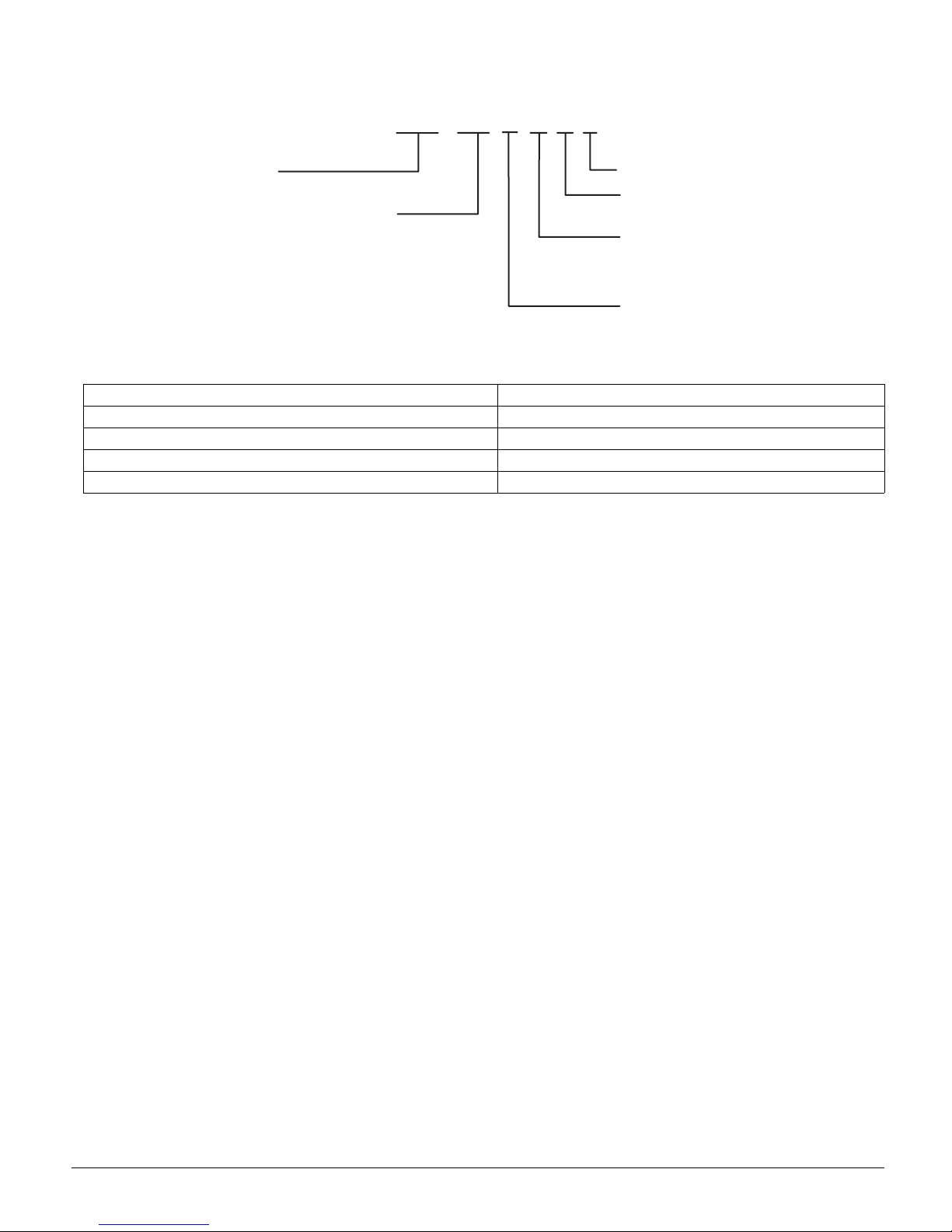
MODEL NOMENCLATURE
M
A
N
0
1
0
A
odel
HP = Air Cooled Heat Pump
ominal Capacity (tons)
90 = 7-1/2
20 = 10
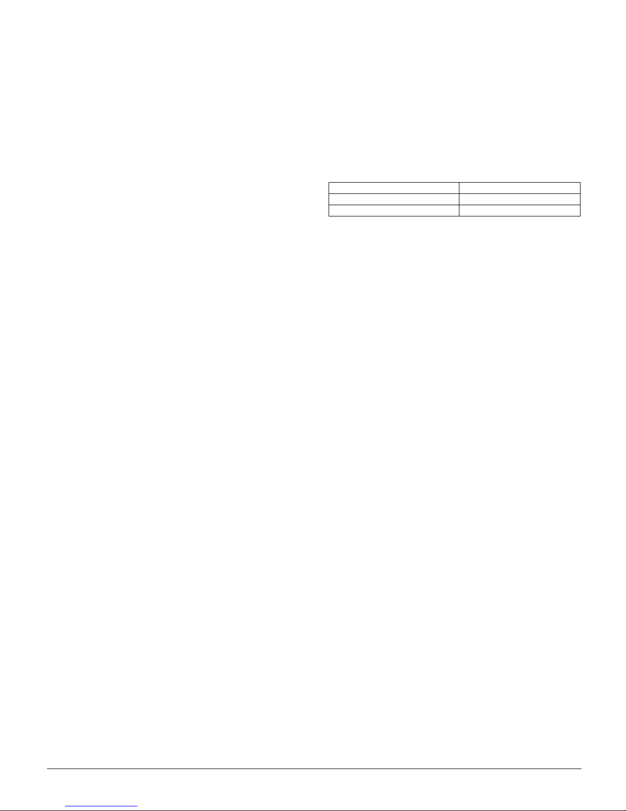
Table 1: Unit Nameplate Model Number Identifier
Unit Nameplate McQuay Model Number
CPLE090-3C AHP090APEY
CPLE090-4C AHP090AQEY
CPLE120-3C AHP120APEY
CPLE120-4C AHP120AQEY
AHP 090
PEY
Future Use
EER
E = 10.1
Voltage/Phase
P = 208-230/3/6
Q = 460/3/60
Vintage
IM-811 Page 3
Page 4
INTRODUCTION
General Description
These installation instructions cover the outdoor installation of
split system heat pumps from 7-½ to 10 tons. See the product
catalog applicable to your model for information regarding
specifications applicable to your model and accessories.
Receiving Inspection
McQuay products are carefully inspected prior to shipment
and the carrier has assumed responsibility for loss or damage
upon acceptance of the shipment.
Upon receiving your shipment, check all items carefully
against the Bill of Lading. Inspect the unit and/or accessories
for shipping damage as soon as they are received. Immedi
ately file claims for loss or damage, either shipping or concealed, with the shipping company.
Check the unit nameplate to verify the model number and electrical characteristics are correct. In the event an incorrect unit
is shipped, it must be returned to the supplier and must NOT
be installed. The manufacturer disclaims all responsibility for
the installation of incorrectly shipped units.
Codes and Regulations
This product is designed and manufactured to permit installation in accordance with National Codes. System design should,
where applicable, follow information presented in accepted
industry guides such as the ASHRAE Handbooks. It is the
installer' s responsibility to install the product in accordance
with National Codes and/or prevailing local codes and regula
tions. The manufacturer disclaims all responsibility for equip-
ment installed in violation of any code or regulations.
Important Message to the Owner
Read these instructions carefully and keep them near the product for future reference. Although these instructions are
addressed primarily to the installer, useful maintenance infor
mation is included. Have the installer acquaint you with the
operation of the product and periodic maintenance require
ments.
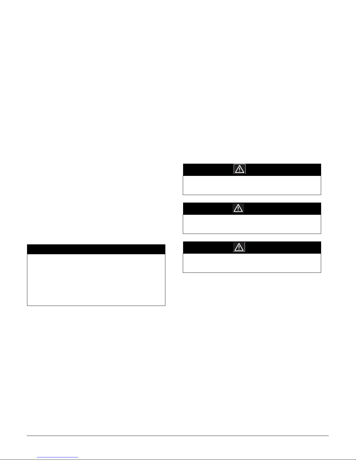
Recognize Safety Symbols, Words, and Labels
The following symbols and labels are used throughout this
manual to indicate immediate or potential hazards. It is the
owner's and installer's responsibility to read and comply with
-
all safety information and instructions accompanying these
symbols. Failure to heed safety information increases the risk
of property damage and/or product damage, serious personal
injury or death. Improper installation, operation and mainte
nance can void the warranty.
DANGER
Immediate hazards which WILL result in property
damage, product damage, severe personal injury and/
or death.
WARNING
-
Hazards or unsafe practice CAN result in property
damage, product damage, sever personal injury and/or
death.
-
-
-
IMPORTANT
The United States Environmental Protection Agency
(EPA) regulations cover introduction and disposal of
refrigerants in this unit. Failure to follow those
regulations can harm the environment and lead to
substantial fines. Because regulations can change, a
certified technician should perform any work done on
this unit. If you have any questions, please contact the
local office of the EPA.
Important Message to the Installer
This equipment is to be installed by an experienced installation
company and fully trained personnel. Carefully read all
instructions and take into account any special considerations
prior to installing the unit. Give this manual to the owner and
explain its provisions.
CAUTION
Hazards or unsafe practices which CAN result in
property damage, product damage, and/or personal
injury.
Replacement Parts
Replacement parts can be obtained by contacting McQuay at
1
-800-37-PARTS. When contacting McQuay for service or
replacement parts, refer to the model number and serial num
ber of the unit as stamped on the nameplate attached to the
unit.
-
Page 4 IM-811
Page 5
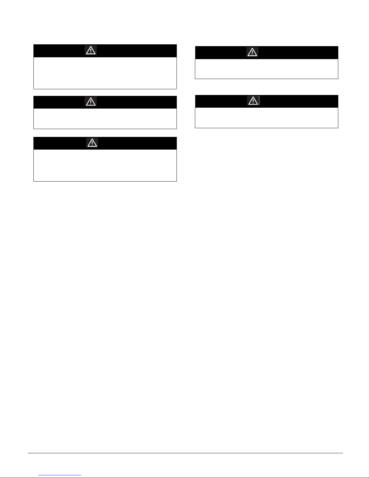
GENERAL WARNINGS
WARNING
Before servicing or installing this equipment, the
electrical power to this unit must be in the "OFF"
position. More than one disconnect may exist. Failure
to disconnect power can cause electrical shock, serious
personal injury or death.
WARNING
The unit must have an uninterrupted, unbroken
electrical ground. Failure to properly ground can cause
severe personal injury or death.
DANGER
Installation and service by trained, qualified technicians
only. High pressure and electricity can cause severe
personal injury or death. Observe ALL warnings
contained in this manual and the labels/tags attached to
the equipment.
WARNING
When installing or servicing this equipment wear
protective gloves, gear and eyeware. Also observe
special safety requirements (hard hats etc.).
CAUTION
To protect the unit when welding close to the painted
surfaces, use a quenching cloth to prevent scorching or
marring of the equipment finish.
IM-811 Page 5
Page 6
PRODUCT DESCRIPTION
When matched with the appropriate air handler(s) or evaporator coil(s) the AHP090/120 heat pump complies with the minimum efficiency equirements found in ASHRAE 90.1-1999.
See the product catalog for the indoor model selection recom
mendation.
Units operate in the same manner as most heat pumps. However, these products use a TXV in lieu of a flowrater/piston
system for refrigerant management.
Units are intended for use with a single stage room thermostat. This thermostat is not supplied with this equipment. Only
thermostats that use 24-volt control circuitry are to be used.
Table 2: Physical Data
Net Weight (Lbs.) 365 415
Shipping Weight (Lbs.) 390 440
Refrigerant R-22
Compressor Type Scroll
Quantity 1
Oil Charge Initial/Recharge 85/81 110/106
Condenser Fan Type Propeller
Fan Diameter (in) 26
Fan Motor Type Direct Drive PCS
Fan Motor (HP) 1
Fan Motor (RPM) 110 0
Nominal Cond. Airflow (CFM) 6600
Condenser Coil Material Riffled Copper Tubes / Al Fins
Face Area (Ft2)
Refrigerant Connections Sweat Type
Suction Line Connection (in) 1-3/8
Liquid Line Connection (in) 5/8
High Pressure Control (PSIG) 425 Cut-out / Manual Reset
Low Pressure Control (PSIG) 7 Cut-out / 25 Cut-in
Thermal Expansion Valve 1
AHP090 AHP120
30
DUCKWORK CONSIDERATIONS
For proper performance, size the indoor ductwork to accommodate 375-425 CFM per ton of cooling with a static pressure
not to exceed .5" WC. Inadequate ductwork that restricts air
flow can result in improper cooling performance and compressor failure.
SITE SELECTION
This unit is designed for outdoor installations only.
Air Supply
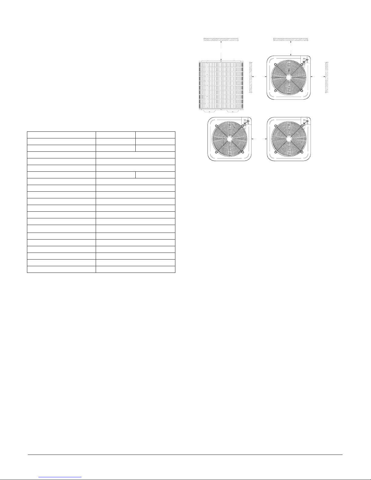
Units are air-cooled heat pumps. To provide optimum unit
performance, the installation site should provide unobstructed
airflow. See Figure 1 for minimum clearances from other aircooled condensers/heat pumps and obstructions such as walls
or overhangs.
Figure 1. Recommended Clearances
60"
12"
-
12"
24"
Refrigerant System Requirements
The selected site should be no greater than 50’ below or 70’
above the evaporator section. For optimum performance, use
the minimum length of interconnecting tubing. Where possi
ble, minimize the amount of bends and turns.
Wiring and Tubing Protection
Electrical wiring and refrigerant tubing is to be protected from
damage due to incidental contact, such as being walked upon.
Vibration and Sound Control
Units are engineered to produce the minimum sound and
vibration. To minimize sound or vibration issues, securely
mount the unit to a surface that is:
•Solid
• Greatest practical mass
•Ridged
• Minimum radiating surface
Where possible, the slab for a ground level unit should not be
connected to the wall or the building.
Prohibited Locations
Do not locate this unit in the following locations:
• Inside a building
• Directly under a vent termination from a gas appliance
• Within 3 feet of a gas appliance vent
• Where water may rise into the unit
12"
-
Note: Adequate service clearances must also be consid-
ered.
Page 6 IM-811
Page 7

TYPICAL INSTALLATION
A
Typical locations for the unit are slab mounted and roof
mounted. For unit weight data, see the "Product Description"
section of this manual.
Slab Mounting
The slab must be capable of supporting the weight of the unit.
The slab should be a minimum of 6" wider than the unit in all
directions. If required, the slab should be elevated to help
avoid water damage due to flooding. Before installing the unit
onto a slab, the wooden shipping skid must be removed.
Roof Mounting
Give careful consideration to the load carrying capability of
the roof. If possible, locate the unit where walls or partitions
can offer additional support. If doubt exists regarding the
integrity of the roof or its supporting structure, consult a struc
tural engineer.
RIGGING
WARNING
All panels must be in position and secured before lifting
this equipment. Dislodged panels cause equipment
damage, severe personal injury or death.
UNIT CORNER WEIGHT
Use Figure 3 and Table 3 for determining the unit corner
weight. The unit net weight and shipping weight is provided
in the “Product Description” section of this manual.
Figure 3. Unit Corner Weight
35.5"
D
C
35.5"
B
-
Table 3: Unit Corner Weight
Corner AHP090 AHP120
A 95 Lbs. 110 Lbs.
B 95 Lbs. 110 Lbs.
C 80 Lbs. 85 Lbs.
D 95 Lbs. 110 Lbs.
REFRIGERANT TUBING
41.5"
Figure 2. Rigging Unit for Lifting
When lifting the unit, use spreader bars (field supplied) to help
avoid damage from lifting cables/straps. Use protective mate
rial, such as plywood, behind the cables/straps to help avoid
damage to the cabinet louvers.
Arrange the straps to form a central suspension point (see Figure 2). When raising and setting the unit, observe all safety
rules. When the unit is in position, the wooden shipping skid
and all lifting materials must be removed.
CAUTION
Wrap service valves with a wet rag or similar approved
thermal heat trap around the valve to avoid damage
due to overheating.
WARNING
To avoid severe personal injury, wear protective
clothing and eye protection when making any welded
connection.
Preparing the Tubing
All cut ends are to be round, burr free and cleaned. Failure to
follow this practice can result in refrigerant leaks.
Post Brazing
Quench all welded joints with water or a wet rag.
Piping Size
Using a carefully estimated length of refrigerant tubing (distance between condenser and evaporator), use Table 4 to determine the tubing diameter:
Table 4: Tubing Diameter For Refrigerant Tubing Length
-
Model
AHP090 5/8 1-1/8 5/8 1-3/8 5/8 1-3/8 5/8 1-3/8
AHP120 5/8 1-1/8 5/8 1-5/8 5/8 1-5/8 5/8 1-5/8
L = Liquid Line
S = Suction Line
* = Full Rating Line Size
0"-24’ *25’-49’ 50’-74’ 75’-99’
L S L S L S L S
Outside Diameter Line Size (in)
IM-811 Page 7
Page 8
Suction Line Insulation
All suction lines must be insulated with a recognized tubing
insulation that is a minimum of 3/8" thick.
Solder
Solder should consist of a minimum of 2% silver.
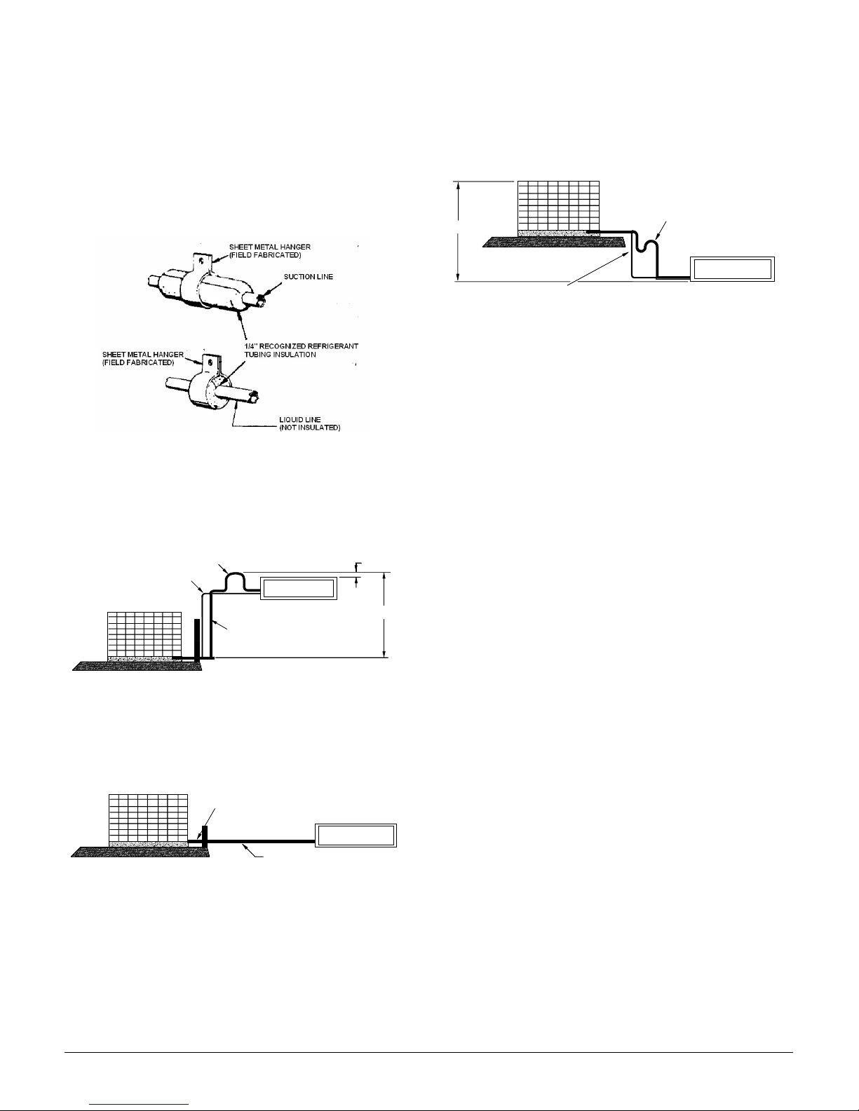
Hangers and Isolation
All refrigerant lines must be isolated from the structure and
supported with hangers. See Figure 4 for details.
Figure 4. Hangers and Isolation
Inverted Suction Line Loop
When the condenser is located at the same level or above the
evaporator section, an inverted loop must be employed on the
suction line. This practice will prevent liquid refrigerant from
migrating into the compressor during shutdown (see Figure 5).
Figure 5. Inverted Suction Line Loop
8'
50' MAX
LIQUID LINE
CONDENSING UNIT
INVERTED LOOP
EVAPORATOR BLOWER
SUCTION LINE
Condenser Above the Evaporator
When the condenser is located 4’ or greater above the evaporator section, a suction line oil trap is to be used at the base of the
riser. An additional oil trap is to be added for each 20’ of verti
cal riser. See the Figure 7.
Figure 7. Suction Line Oil Trap
CONDENSING UNIT
ADDITIONAL SUCTION LINE OIL
70' MAX
LIQUID LINE
SUCTION LINE OIL TRAPS WHEN INDOOR UNIT
IS 4 FEET OR MORE BELOW OUTDOOR UNIT
TRAP FOR EACH 20' RISE OF PIPE
EVAPORATOR BLOWER
Filter Drier and Sight Glass
A liquid line filter drier is factory installed. A sight glass/
moisture indicator is provided with the unit. This is to be field
installed on the liquid line as close as practical to the service
valve.
Holding Charge
Units are factory shipped with a 2-pound R-22 holding charge.
When welding, introduce an inert gas (e.g. nitrogen) through
the tubing to help prevent the formation of copper oxide inside
the tubing.
TXV
For improved refrigerant management, the evaporator coil is to
be equipped with a thermal expansion valve (TXV).
Liquid Line Solenoid
Add a field supplied liquid line solenoid to the liquid line as
close as possible to the evaporator coil. The solenoid must be
wired to close when the compressor stops to prevent refriger
ant migration in the “OFF” cycle.
-
-
Evacuation and Charging
See the “Evacuation and Charging” section of this manual for
Oil Return
instructions.
To facilitate oil return to the compressor a horizontal suction
line should be pitched (1/2" per 10’) toward the condensing
unit (see Figure 6).
Figure 6. Suction Line Pitch
CONDENSING UNIT
Page 8 IM-811
PITCH SUCTION LINE TOWARD OUTDOOR
UNIT 1/2" FOR EVERY 10' OF LINE
LIQUID LINE
EVAPORATOR BLOWER
Page 9

ELECTRICAL WIRING.
WARNING
Before servicing or installing this equipment, the
electrical power to this unit must be in the “OFF”
position. More than one disconnect may exist. Failure
to observe this warning can result in an electrical shock
that can cause personal injury or death.
WARNING
The unit must have an uninterrupted, unbroken
electrical ground. Failure to properly ground can result
in severe personal injury or death.
CAUTION
To avoid risk of fire or equipment damage, use only
copper conductors.
Inspection of the Building Electrical Service
This unit is designed for 3-phase operation. DO NOT OPERATE ON A SINGLE PHASE POWER SUPPLY. Measure the
power supply to the unit. The supply voltage must be in
agreement with the unit nameplate power requirements and
within the range shown in Table 5.
Table 5: Minumum/Maximum Supply Voltage Range
Model Vol tag e
AHP090 208/230 187 253
AHP090 460 414 506
AHP120 208/230 187 253
AHP120 460 414 506
Voltage Balance
The supply voltage shall be unbalance (phase to phase) within
2%. To calculate the percentage of voltage unbalance use the
following formula:
Percentage
Voltage = 100 x
Unbalance
Max. Voltage Devation From Avg.Voltage
Avg. Voltage
Example
Avg. Voltage =(220 + 216 + 213) / 3
Max. Deviation from Avg. =220 - 216 = 4
% Voltage Unbalance = 100 x 4 / 216
Minimum Supply
Voltage
L1 - L2 = 220V
L2 - L3 = 216V
L1 - L3 = 213V
=649 / 3
=216
= 400 / 216
= 1.8%
Maximum Supply
Voltage
Determine Wire Size
The selection of the appropriate supply wire size is important
to the operation of the equipment. When selecting the wire
size, the following are important elements of the decision:
• The wire size is sufficient to carry the Minimum Circuit Ampacity (MCA). The unit MCA can be found on the equipment nameplate and the following table.
Table 6: Minimum Circuit Ampacity
• The wire is appropriately sized to allow for no more than a 2%
• Refer to the latest edition of the National Electric Code or, in
Table 7: Maximum Allowable length in Feet to Limit Voltage
drop to 2%*
*Based on NEC 1996
Example
Model Vol tag e MCA
AHP090 208/230 37.8
AHP090 460 18.8
AHP120 208/230 43.3
AHP120 460 22.2
voltage drop from the building breaker/fuse panel to the unit.
Canada, the Canadian Electric Code when determining the correct wire size. The following table shows the current carrying
o
capabilities for copper conductors rated at 75
C with a 2% volt-
age drop.
Wire Size
(AWG)
14 75 50 37 NR NR NR NR NR
12 118 79 59 47 NR NR NR NR
10 188 125 95 75 63 54 NR NR
8 301 201 150 120 100 86 75 68
6 471 314 235 188 157 134 118 11 0
10 15 20 25 30 35 40 45
Min. Circuit Ampacity (MCA)
A 208/230 volt AHP120 is to be installed. The distance
from the building breaker box to the unit is 75’. Calculate
the minimum wire size assuming no more than 2% voltage
drop.
MCA = 43.3 (from nameplate and table).
Applying previous table wire sizes less than #8 AWG cannot be used for circuits which have a rating of 45A. The #8
wire is not suitable because the maximum length for a 45A
circuit is 68’. Solution, a #6 AWG wire is suitable up to 110’.
Note: It is the contractors responsibility to follow the NEC
(USA) or CEC (Canada) when sizing the service wire for
this unit.
IM-811 Page 9
Page 10
Service Disconnect Box
A service disconnect box is required as per NEC.
Fuse – HACR Breakers
Protection is to be provided by either fuses or HACR type
breakers. Refer to the unit nameplate and the following table
for the maximum overcurrent protection permitted.
Table 8: Maximum Overcurrent Protection
Model Vol tag e *Max. Fuse
AHP090 208/230 60
AHP090 460 30
AHP120 208/230 60
AHP120 460 35
* Fuse or HACR Breaker of same value.
Line Voltage Wiring
Run all line voltage wiring through conduit from the service
disconnect box to the unit. Refer to the NEC (in Canada CEC)
for the correct size conduit based on the wire size. The conduit
must enter the control box through the hole provided in the
bottom. Note: hole is sized for ¾” conduit. If permitted by
code, flexible conduit is preferred to minimize vibration trans
mission from the unit to the building.
Connect the line voltage wires to the L1, L2, and L3 terminals
of the definite purpose contactor (located in the unit control
box). Refer to the wiring diagram attached to the unit when
making these connections. The unit wiring diagram is also
included at the end of this manual.
The unit must be grounded. The electrical ground circuit must
consist of an appropriately sized electrical wire connecting to
the ground lug in the unit control box and wire to the building
electrical service panel. Other methods of grounding are per
mitted if performed in accordance with the National Electric
Code (NEC)/American National Standards Institute (ANSI)/
National Fire Protection Association (NFPA) 70 and local/state
codes. In Canada, electrical grounding is to be in accordance
with the Canadian Electric Code CSA C22.1.
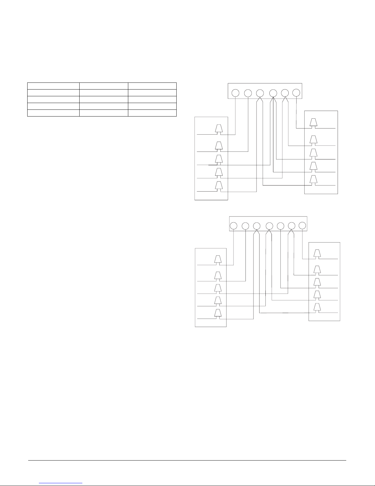
Low Voltage Connections
Units require a 5-conductor low voltage circuit from the room
thermostat. The wires are to be no smaller than 18 AWG. The
field connection for this circuit is to be made in the unit control
box using wire nuts or other solderless connectors. See Figures
8 and 9 for a typical low voltage hook-up.
Figure 8. Single Stage Low Voltage Hook-up
THERMOSTAT
G
Y
OC
CONDENSING
UNIT
AHP090/120
YELLOW
ORANGE
RED
-
WHITE
BLUE
W2
R
Figure 9. Two Stage Low Voltage Hook-up
THERMOSTAT
Y
CONDENSING
UNIT
AHP090/120
OC
W1
W2
GR
-
YELLOW
ORANGE
RED
WHITE
BLUE
AIR
HANDLER
SAH090/120
GREEN
RED
BROWN
WHITE
BLUE
AIR
HANDLER
SAH090/120
GREEN
RED
BROWN
WHITE
BLUE
Page 10 IM-811
Page 11

Control Box Components
See Figure 10 for the location of the electrical components.
Figure 10. Electrical Component Locations
SYSTEM EVACUATION AND
CHARGING
WARNING
To avoid possible explosion, injury or death,
refrigerants must be handled by trained, experienced
qualified technicians only.
WARNING
Refrigerants are heavier than air. They can “push out”
the oxygen in your lungs or in any enclosed space. To
avoid suffocation or death.
• Never sniff refrigerant.
• Never purge refrigerant.
WARNING
If an indoor refrigerant leak is suspected, thoroughly
ventilate the area and repair leak before beginning
work.
WARNING
Liquid refrigerant can be very cold. To avoid possible
frostbite or blindness, avoid contact and wear protective
gloves and eyeware. If liquid refrigerant contacts your
skin or eyes, seek medical help immediately.
Always follow EPA regulations. Never burn refrigerant
as poisonous gas can be produced.
WARNING
To avoid possible explosion, use refrigerant cylinders
properly:
• If you must heat a cylinder for faster charging, partly
immerse it in warm water. Never apply flame or
steam to the cylinder.
• Store cylinders in a cool, dry place. Never use a cylinder as a platform or a roller.
• Never add anything other than R-22 to an R-22 cylinder.
• Never fill a cylinder more than 80% full of liquid
refrigerant.
• When removing refrigerant from a system, use only
returnable (not disposable) service cylinders. Check
the cylinder for its pressure rating and hydrostatic
test date. Check the cylinder for any damage that
may lead to a leak or explosion. If in doubt, do not
use the cylinder.
Leak Test
WARNING
To avoid the risk of fire or explosion, never use oxygen,
high pressure or flammable gas for leak testing of a
refrigeration system.
1. Verify that both hand valves on the gauge manifold are
closed relative to the center port (i.e., turned in all the
way). Attach this gauge manifold to the service valves on
the unit.
WARNING
To avoid possible explosion, the line from the nitrogen
cylinder must include a pressure regulator and a
pressure relief valve. The pressure relief valve must be
set to open at no more than 150 psig.
2. Connect a cylinder of dry nitrogen to the center port on
the gauge manifold.
3. Open the hand valve a minimal amount on the line coming from the nitrogen cylinder.
4. Open the high pressure valve on the gauge manifold.
Pressurize the refrigerant lines and the indoor coil to 150
psig (1034 kPA).
WARNING
To avoid possible explosion or equipment damage, do
not exceed 150 psig when pressure testing.
After you reach 150 psig, close the valve on the nitrogen cylinder. Disconnect it from the gauge manifold. If you plan to use
an electronic leak detector, add a trace of R-22 to the system (if
permitted by current EPA regulations).
5. Apply a soap solution on all connections and joints. If you
see bubbles, you have a leak. Mark these locations.
6. Use the gauge manifold to carefully release the nitrogen
from the system. If leaks are found, repair them. After
repair, repeat the above pressure test. If no leaks exist,
proceed to system evacuation.
IM-811 Page 11
Page 12
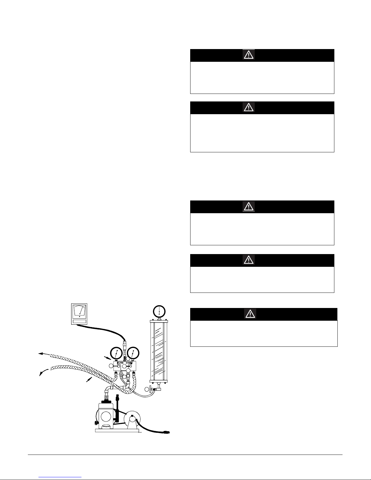
SYSTEM EVACUATION
1. Connect the vacuum pump, high vacuum manifold set
with high vacuum hoses, thermocouple vacuum gauge
and charging cylinder as shown in Figure 10. Begin with
all valves fully closed.
2. If service fill valves are used for evacuation, use a core
remover to lift the valve core. It provides greater effi
ciency.
3. Confirm proper pump and gauge operation. Open the
shutoff valve that leads to the high vacuum gauge mani
fold. Start the pump. When the compound gauge (low
side) reading drops approximately 29 inches of vacuum,
open the valve to the thermocouple vacuum gauge and
evacuate until the gauge reads 250 microns or less.
4. Close the valve to the thermocouple vacuum gauge. This
avoids potential gauge damage from “pegging the meter”.
5. Open the high and low side valves on the gauge manifold.
Keeping the valve on the charging cylinder closed, open the
valve on the gauge manifold that leads to the cylinder.
6. Evacuate the system to about 29 inches Hg as measured by
the compound (low side) gauge.
7. Open the valve to the thermocouple vacuum gauge. Evacu-
ate until the gauge reads 250 microns or less.
8. Close the valve to the vacuum pump. Wait five minutes,
then check the pressure on the thermocouple vacuum
gauge:
• If the pressure is not more than 1500 microns, the system is
leak-free and properly evacuated. Proceed to Step 9.
• If the pressure rises, but holds at about 5000 microns, moisture and non-condensibles are still present. Open the valve
to the vacuum pump, and go back to Step 7.
• If the pressure rises above 5000 microns, a leak is present.
Go back to “Leak Testing” section above
9. Close the valve to the thermocouple vacuum gauge. Close
the valve to the vacuum pump. Shut off the pump.
Figure 11. System Evacuation Components
THERMOCOUPLE
VACUUM
GAUGE
DIAL-A-CHARGE
TO
RELATED
GAUGE
PORTS OF
COND. UNIT
LARGE DIAMETER
BRAIDED VACUUM
A. LOW SIDE VA LVE
B. HIGH SIDE VALVE
C. VACUUM PUMP
D. THERMOCOUPLE GAUGE
E. MANIFOLD GAUGE
F. CHARGING CYLINDER
HIGH VACUUM
MANIFOLD
HOSES
CHARGING CYLINDER
LOW SIDE
GAUGE
HIGH VACUUM PUMP
A
HIGH SIDE
GAUGE
D
B
C
E
F
-
-
PRELIMINARY CHARGE
ADJUSTMENT
CAUTION
See the wiring diagram or outdoor unit specification
sheet to determine if this unit has a crankcase heater. If
it does, you must connect electrical power to the unit for
four hours before operating the compressor. Failure to
do so can result in compressor damage.
CAUTION
During all installation and service work, follow all
regulations of the Environmental Protection Agency.
(This system uses R-22 - an HCFC [Hydrogenated
Chlorofluorocarbon]). Violation of EPA regulations can
result in environmental damage, fines or other
penalties.
Use a male hex head wrench (5/16" for liquid) to carefully
open the liquid valve stem on the unit. Use a service wrench
or crescent wrench to open the suction ball valve. The valve is
fully open with a 90-degree turn (i.e. the stem is inline with the
valve flow direction).
The outdoor unit is factory charged with 2 lb. R-22.
CAUTION
Use only refrigerant that is certified to meet ARI
Standard 700. Used refrigerant can cause compressor
damage and will void the warranty. Most portable
machines cannot clean used refrigerant well enough to
meet this ARI Standard.
CAUTION
When adding additional refrigerant to a system, add
only refrigerant vapor (not liquid) through the suction
valve (low side) on the outdoor unit. Any other practice
can cause compressor damage.
FINAL CHARGE ADJUSTMENT
CAUTION
Never operate the compressor with the suction valve
closed to “test the compressor pumping efficiency”. In
some cases, this can cause serious compressor
damage.
For 25’ of line set, the 7-1/2-ton charge is approximately 17 lb.
For 25’ of line set, the 10-ton charge is approximately 20 lb.
Do not start with these amounts.
For installations greater than 25’ of line set, the indoor unit airflow, condensing unit location and number of tubing fittings
will have an impact on final unit charge amount. Start with half
of the 25’ line set charge and proceed.
Turn the electrical power on, and let the system run. Wait for
the refrigerant pressures to stabilize.
Page 12 IM-811
Page 13
EXPANSION VALVE INDOOR COILS
NOTE: EXPANSION VALVE BULB must be in place on
suction line and insulated.
Outdoor Temperature Over 60°F. When the outdoor temperature is above 60°F, charge the system with the room thermostat set in the “Cooling” mode and the fan operating in the
“Auto” position.
Outdoor Temperature Less Than 60°F. If the outdoor
temperature is less than 60°F, charge the unit with the room
thermostat set in the “Heat” mode and the fan set in the “Auto”
position.
System Charging – Cooling Mode
The following describes adjusting the refrigerant charge with
the ambient temperature in excess of 60°F and the room ther
mostat adjusted as indicated above.
At stabilized cooling conditions and with an outdoor temperature of 60°F or higher, the system should have from 9°F to
13°F subcooling. For a proper subcooling reading, measure the
refrigerant pressure and temperature at the outdoor unit liquid
line service valve. If you have less than 9°F subcooling, add
charge. If you have more than 13°F subcooling, remove
charge.
While reaching the proper subcooling level, it is important to
know the discharge line temperature. This temperature should
be at least 80°F over ambient or the unit is flooding back to the
compressor. If flooding (i.e. low discharge line temperature)
occurs, adjust the valve stem on the expansion valve inward
(clockwise viewing the end of the expansion valve). This will
increase the super heat.
After achieving the proper subcooling and a sufficient discharge temperature, make small adjustments to the expansion
valve stem to reach 8°F to 10°F of superheat. Adjusting the
valve stem in (or clockwise) increases superheat. Adjusting the
valve stem out (or counter clockwise) decreases superheat. If
the system is performing properly, re-install the service port
caps and the valve bonnets. With the valve opened, the valve
bonnet is the primary seal against refrigerant leaks. Apply two
drops of clean oil to the cap threads, allowing the oil to run
down to the inner cap seal surface. Close the caps finger-tight.
Then tighten the cap an additional two to three hex flats.
System Charging – Heating Mode
The following method can be employed as a method to check
the system charge in the heating mode by measuring the hot
gas discharge at the compressor.
1. Allow the system to operate for at least 20 minutes.
2. Attach and insulate an electronic thermometer to the hot
gas discharge line mid way between the compressor and the
reversing valve. Note: The thermometer must be well
insulated to prevent ambient influences.
3. Adjust the charge to maintain a clear sight glass.
4. Allow the compressor to operate for about 10 additional
minutes and measure the hot gas discharge temperature.
5. Using an additional electronic thermometer, measure the
ambient.
6. Adjust the charge until the hot gas temperature equals 105°
F + ambient (+ or – 5°F). Remove charge to increase the
temperature.
Note: When adjusting the charge, allow the compressor to
operate for about 10 minutes before taking readings.
Note: Subsequent opening and replacing of the cap will
require only 1/2 to 1 hex flat. See the table below for
the torque required for an effective seal on the valve
bonnet (1/6 turn past finger tight).
Table 9: Cap Torqure
After closing the valve bonnet, perform a final refrigerant leak
-
Tubing Size Torque (Foot-Pounds)
5/8 14
1 3/8 16
test on the valves and sweat connections. Return the room
thermostat to the desired settings.
DEFROST CONTROL (DC)
Units use a time/temperature method for defrost. A thermal
sensor is attached to the condenser coil to determine the out
door coil temperature. The coil temperature sensor is electrically “Normally Open” and is wired to the electronic defrost
control that is located in the control box.
Both coil temperature and compressor run time determine
defrosting of the outdoor coil. Adjustments to the defrost tim
ing selection can be changed from the 60 minute factory setting to either 30 or 90 minutes by moving the jumper on the
defrost control. To initiate a defrost, the following statements
must be true:
• The defrost sensor must be closed.
• The compressor run time must equal the timing selection on the
defrost board.
Note: The compressor run time is accumulative during
multiple “heating” cycles. The timer will reset to
zero only when the defrost sensor returns to an open
condition. If the room thermostat is operating in the
“EM HT” mode, no accumulation of compressor
time is recorded.
During defrost, the following actions occur:
1. The reversing valve is energized and the heat pump operates in the cooling mode.
2. The air handler auxiliary heat (if equipped) is activated.
3. The condenser fan motor is shut-off.
If the defrost cycle has not terminated after ten (10) minutes,
the control will override the defrost sensor and revert to a heat
ing mode.
The defrost control has test pins which can be useful when
troubleshooting in the heating mode. These test pins accelerate
the compressor run time counter. The suggested method for
accessing this feature is:
A. Run unit in heat mode.
B. Check unit for proper charge.
Note: Bands of frost indicate low refrigerant charge.
C. Shut off power to unit.
-
-
-
IM-811 Page 13
Page 14

D. Disconnect outdoor fan by removing the purple lead from
the Condenser Fan Defrost Relay.
E. Restart unit and allow frost to accumulate.
F. After a few minutes the defrost thermostat should close. To
verify the position of the thermostat check for 24V between
“DFT” and “C” on the defrost board. Should the defrost
thermostat fail to close after a heavy build-up of frost and
the thermostat is less than 28°F, the thermostat is to be
replaced.
G. After the thermostat has closed, short across the test pins
with a screwdriver blade until the reversing valve shifts.
This could take up to 21 seconds depending upon the posi
tion of the timing setting on the defrost board. Immediately
remove the short upon the action of the reversing valve.
Note: If this short is not removed immediately, the defrost
activity will last only 2.3 seconds.
H. After defrost has terminated (up to 10 minutes) check the
defrost thermostat for 24V between “DFT” and “C”. This
reading should be 0 V (open sensor).
I. Shut off power to the unit.
J. Replace outdoor fan motor wire removed in Step D.
Figure 12. Shunt Section Jumper
TROUBLE SHOOTING
WARNING
Troubleshooting can present hazards of electricity,
rotating parts, sharp edges and weight. troubleshooting
must be done by trained, experienced technicians only.
Improper troubleshooting can result in equipment
damage, severe personal injury or death.
IMPORTANT: Qualified installer/servicer only
When troubleshooting, the first step should always be to check
for clean coils, clean filter(s) and proper airflow. Indoor air
flow should be 375 to 425 CFM per ton of cooling based on
the size of the outdoor unit. The most common way of estab
lishing indoor airflow is heating temperature rise. Indoor airflow will then be (Heating output of equipment) / (1.1 x temp.
rise). In other cases, measurement of external static pressure is
helpful. For details, see the Installation Instructions for your
indoor equipment.
CAUTION
3-Phase Scroll Compressor
The AHP090/120 condenser is equipped with a 3phase scroll compressor. Improper phase can damage
equipment.
-
-
SHUNT
SELECTION
JUMPER
If the unit sounds noisy and/or the suction and liquid pressures
are almost equal, the compressor is operating in the reverse
rotation. Reverse the two (2) incoming power supply leads.
Page 14 IM-811
Page 15
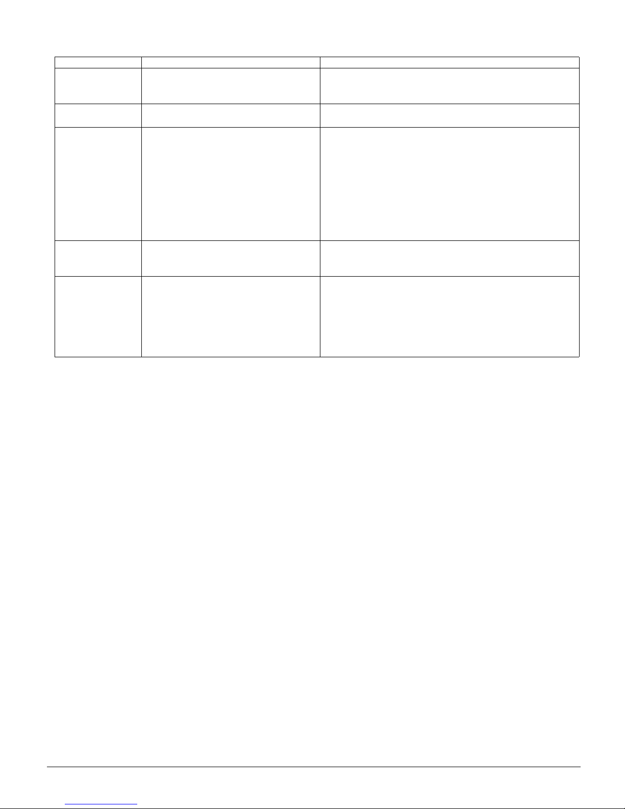
Table 10: Trouble Shooting Analysis - Cooling
COMPLANT PROBABLE CAUSE REMEDY
1. High Head Pressure
2. Low Head Pressure
3. Low Suction Pressure
4. High Suction Pressure
5. Compressor will not
start.
1. Excessive charge of refrigerant in system.
2. Inadequate supply of air across the condenser coil.
3. Non-condensate gases in the system.
1. System low on refrigerant.
2. Compressor valves broken.
1. Liquid line valve closed.
2. Restricted liquid line.
3. The bulb of the thermal expansion valve has lost its
charge.
4. System low on refrigerant.
5. Dirty filters.
6. Coil frosted up.
7. Flash gas in the liquid line.
8. Quantity of air through evaporator not adequate.
1. Expansion valve stuck open.
2. Expansion valve bulb not in contact with suction line.
3. Suction and/or discharge valve leaking or broken.
1. Disconnect switch open.
2. Blow fuse or fuse at disconnect switch.
3. Thermostat set too high.
4. Selector switch in "Off" position.
5. Contactor and/or relay coils burned out.
6. Loose or open electrical connection in either the control or power circuit.
1. Purge or pump-down excessive charge.
2. Make certain that coil is not fouled in any way, or that air is not re-circulating.
3. Purge these gases from the system. Recharge system, if necessary.
1. Charge system until sight glass is clear of bubbles.
2. Replace compressor.
1. Open the liquid line valve.
2. Replace filter-dryer.
3. Detach the bulb from the suction line and hold in one hand. If no liquid refrigerant goes through the valve, replace the valve.
4. Test the unit for leaks. Add refrigerant until sight glass is free from bubbles,
after repairing leak.
5. Clean or replace filter.
6. Defrost and clean coil. Clean or replace filters.
7. Excessive liquid line drop. Check liquid line size.
8. Increase the blower speed.
1. Correct valve action or replace the valve.
2. Fasten bulb securely to suction line.
3. Replace compressor.
1. Close the disconnect switch.
2. Check the cause of failure and replace the fuse.
3. Adjust to lower temperature.
4. Turn selector switch knob to "Cool" position.
5. Replace contactor and/or relay.
6. Inspect and secure all electrical connections.
TROUBLE SHOOTING - Heating
Common Causes of Unsatisfactory Operation of Heat Pumps
on the Heating Cycle include:
Dirty Filters
Dirty filters or inadequate airflow through the indoor coil.
Failure to keep clean filters and adequate airflow (375-425
CFM/ton) will cause excessive discharge pressures that may
cause the high-pressure switch to function.
Low Return Air Temperatures
Return ductwork temperatures that are less than 60°F will
cause low discharge pressure, low suction pressure and exces
sive defrost cycling.
Undercharging
An undercharged system will cause low discharge pressure,
low suction pressure and an accumulation of frost on the lower
section of the outdoor coil.
Poor Termination of Defrost
The defrost sensor must make good contact with the outside
coil return bend or a non-termination of defrost may occur.
Reversing Valve
A reversing valve may not function correctly for the following
reasons:
1. Solenoid does not energize when voltage is present
Replace the reversing valve.
2. No voltage to the solenoid
Check the wiring.
3. The valve will not shift
-
a.Undercharged
Check for leaks
b.Valve body damage
Replace the reversing valve
c.Valve sticking
Replace the reversing valve
IM-811 Page 15
Page 16

WIRING DIAGRAM
Page 16 IM-811
Page 17

IM-811 Page 17
Page 18

Page 19

Page 20

This document contains the most current product information as of this printing. For the most up-to-date
product information, please go to www.mcquay.com.
www.mcquay.com • 800-432-1342
 Loading...