

Page 1

Installation and Maintenance Manual
IM 702-3
Group: Controls
Part Number: IM 702-3
Date: November 2004
Supersedes: IM 702-2
MicroTech II
TM
Applied Rooftop Unit Controller and
Self-Contained Unit Controller
LonWorks® Communication Module
•<Space Comfort Controller (SCC) Module
•<Discharge Air Controller (DAC) Module
Use this manual to physically install the communications module into the unit and connect the unit to your
network. You also need the appropriate McQuay Engineering Data Sheet known as the Protocol Data Packet to
integrate the unit into your network. The Protocol Data Packet contains addressing details, BACnet® and
LonWorks® protocol information, and a list of the data points available to the network. See the Reference
Documents section of this document for part numbers of Protocol Data Packets. These documents are available
from your local McQuay International representative and for downloading at the McQuay International web site:
www.mcquay.com.
© 2004 McQuay International
NOTICE
Page 2

Table of Contents
Reference Documents ................................................................................................................................................................3
General Information ............... ..... .. ......................................................................................................................................4
Description ................................................................................................................................................................................4
Application ................................................................................................................................................................................5
Component Data ........................................................................................................................................................................5
Service Pin ....................................... .. ......................................................................................................................................5
Specifications ............................................................................................................................................................................6
Installation ............................... ..... .. ......................................................................................................................................7
Mounting ...................................................................................................................................................................................7
Mounting a New MicroTech II LonWorks Communications Module ......................................................................................7
Replacing a MicroTech II LonWorks Communications Module ..............................................................................................7
Integration ................................ ..... .. ....................................................................................................................................12
Network Connection ................................................................................................................................................................12
Network Topology .......................... .. ....................................................................................................................................12
Free Topology Networks ................. .. ....................................................................................................................................12
Free Topology Restrictions ............. .. ....................................................................................................................................13
Doubly Terminated Networks ......... .. ....................................................................................................................................13
Doubly Terminated Topology Restrictions .............................................................................................................................14
Addressing and Establishing Communications .......................................................................................................................14
LonWorks Network Addressing ...... .. ....................................................................................................................................14
Commissioning the Network ........... .. ....................................................................................................................................14
External Interface File (XIF) ........... .. ....................................................................................................................................15
Configuring the Unit Controller ..............................................................................................................................................15
Service Information ................. ..... .. ....................................................................................................................................16
Test Procedures .......................................................................................................................................................................16
Replaceable Parts List .............................................................................................................................................................16
Network Connection Plug ............... .. ....................................................................................................................................16
Kits and Wire Harness .................... .. ....................................................................................................................................16
Warranty .................................. ..... .. ....................................................................................................................................17
2 IM702-3
Page 3

Notice
© 2004 McQuay International, Minneapolis MN. All rights reserved throughout the world.
McQuay International reserves the right to change any information contained herein without prior notice. The user is
responsible for determining whether this product is appropriate for his or her application.
The following are trademarks or registered trademarks of their respective companies. Windows from Microsoft
Corporation; BACnet from ASHRAE; LONWORKS from Echelon Corporation; McQuay, MicroTech II from McQuay
International.
Reference Documents
Number Company Title
IM696 McQuay International MicroTech II Applied Rooftop Unit Controller Installation Manual
OM137 McQuay International MicroTech II Applied Rooftop Discharge Air Controller Operation Manual
OM138 McQuay International MicroTech II Applied Rooftop Space Comfort Controller Operation Manual
IM710 McQuay International MicroTech II Vertical Self-Contained Unit Controller Installation Manual
OM711 McQuay International MicroTech II Vertical Self-Contained Discharge Air Controller Operation Manual
OM712 McQuay International MicroTech II Vertical Self-Contained Space Comfort Controller Operation Manual
ED15060 McQuay International MicroTech II Protocol Information Data for McQua y International Applied Rooftop Units
ED15061 McQuay International MicroTech II Protocol Information Data for McQuay International Self-Contained Units
078-0014-01E LonMark Interoperability Assoc. LonMark Layers 1-6 Interoperability Guidelines, Version 3.0
078-0120-01E LonMark Interoperability Assoc. LonMark Application Layer Interoperability Guidelines, Version 3.2
8500_10 LonMark Interoperability Assoc. LonMark Functional Profile: Space Comfort Controller, Version 1.0
8610_10 LonMark Interoperability Assoc. LonMark Functional Profile: Discharge Air Controller, Version
078-0156-01G Echelon Corporation LonWorks FTT-10A Free Topology Transceiver Users Guide
McQuay International documents are available at www.mcquay.com.
IM702-3 3
Page 4

General Information
This manual contains the information you need to install the communication modules and incorporate it into the network,
and maintain it.
! WARNING
Electric shock hazard. Can cause personal injury or equipment damage.
This equipment must be properly grounded. Connections and service to the MicroTech II control panel must be
performed only by personnel who are knowledgeable in the operation of the equipment being controlled.
! CAUTION
Static sensitive components. Can cause equipment damage.
Discharge any static electrical charge by touching the bare metal inside the control panel before performing any
service work. Never unplug cables, circuit board terminal blocks, or power plugs while power is applied to the panel.
NOTICE
This equipment generates, uses and can radiate radio frequency energy and, if not installed and used in accordance
with this instruction manual, may cause interference to radio communications. It has been tested and found to comply
with the limits for a Class A digital device, pursuant to part 15 of the FCC rules. These limits are designed to provide
reasonable protection against harmful interference when the equipment is operated in a commercial environment.
Operation of this equipment in a residential area is likely to cause harmful interference in which case the user will be
required to correct the interference at his or her own expense. McQuay International disclaims any liability resulting
from any interference or for the correction thereof.
Description
A MicroTech II LonWorks Communications Module provides the interface between a MicroTech II unit controller and a
LonWorks Local Operating Network (LON). It translates the LonTalk variables used on the network to the variables used in
the unit controller and vice versa. Two versions are available: one in accordance with the LonMark Space Comfort Control
(SCC) Functional Profile and one in accordance with the LonMark Discharge Air Control (DAC) Functional Profile.
Profiles are interpreted in loaded programs (firmware). Each profile is interpreted in a separate MicroTech II LonWorks
Communications Module. This manual covers both.
Each MicroTech II LonWorks Communications Module is a printed circuit board that plugs onto the MicroTech II Main
Control Board. Figure 1 is an outline drawing with dimensions of a printed circuit board.
Figure 1. MicroTech II LonWorks Communications Module
3.750
0.250
IM702-3 4
0.250
6.750
Page 5
Application
A MicroTech II LonWorks Communications Module connects the MicroTech II unit controller to the Building Auto mation
System (BAS) on a LonWorks network. It is the interface adapter for the exchange of LonTalk variables between the
network and the unit contr oller. The MicroTech I I LonWorks Co mmunicatio ns Module tra nslates the LonWorks var iables
of the profile into the native information of the unit controller. Figure 2 shows the MicroTech II LonWorks
Communications Module and unit controller integrated into a BAS. Refer to the appropriate Unit Operation manual for
keypad details. See Reference Documents for part numbers.
Figure 2. Building Automation Sys tem
LonWorks
FTT-10A
Network
MicroTech II
Main Control
Board
MicroTech II
LonWorks
Communications
Module
MicroTech II
Keypad
LonWorks Work S tation
LonWorks
Interface
Adapter
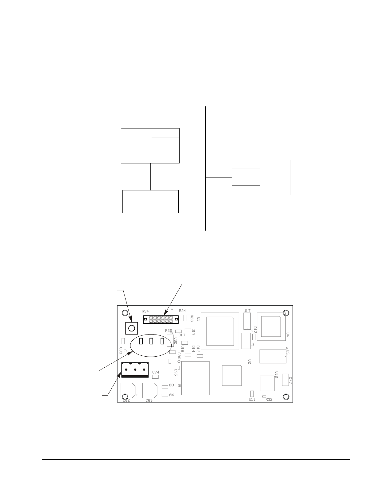
Component Data
Figure 3 shows the location of the major components of the MicroTech II LonWorks Communications Module.
Figure 3. MicroTech II LonWork s Communicati ons Modu le Ma jor Compo nen ts
Service Pin
SW1
J6
12-Pin Header
Light Emitting Diodes
123
P8 Connector
Service Pin
The service pin, switch SW1, generates a service pin message, which contains the Neuron ID and the program code
identification of the node. A service pin message is a network message that is generated by a node and broadcast on the
network. It can be used to commission the LonWorks network.
IM702-3 5
P8
DS1
DS2
DS3
Page 6

Light Emitting Diodes (LEDs)
The communications module has three LEDs to indicate communication activity and status of the communication module
LED Function
DS1
DS2
DS3
• Lights when the service pin is pressed
• Lights when there is a problem with the module
• On Steady during normal operation
• Blink during a Wink command
• Flicker during Communications Activity
• Blink during a Wink command
LonWorks Network Connector (P8)
The P8 connector connects the MicroTech II LonWorks Communications Module to the LonWorks FTT-10A bus
Pin Designation Function
1 None No Connection
2 - (minus sign) FTT-10A
3 + (plus sign) FTT-10B
12-Pin Header
The 12-pin header, J6, connects the unit controller Main Control Board to the LonWorks communications module through
the bottom of the communications module.
LonMark Profile Software
The MicroTech II LonWorks Communications Module software translates the Standard Network Variable Types (SNVTs)
and Standard Network Configuration Parameters (SCPTs) in accordance with the LonMark profiles used on the LonWorks
network into the variables and parameters used in the MicroTech II Main Control Board.
Neuron
The basis of the communications module is an Echelon Neuron chip. Each Neuron chip stores a globally (i.e., worldwide)
unique, 48-bit serial number called the Neuron ID. The Neuron ID can be used to address the device on the LonWorks
network.
Transceiver
The Echelon Corporation Free Topology Transceiver (FTT-10A) is used to communicate on the LonWorks network. The
network topology may consist of a: star, daisy-chain, or other topology. Data transmission rate on the network is 78 kbps
(baud).
Specifications
Characteristic Description
Network Topology Flexible Free Topology
Neuron Chip Processor 3150
Free Topology Transceiver (FTT-10A) 50051
Cable Types TIA Category 5 (recommended)
Maximum Bus Length 1476 ft (450) meters per segment
Maximum Node Separation 820 ft (250 meters)
Data Transmission Two-wire, half duplex
Data Transmission Rate 78 kbps (baud)
6 IM702-3
Page 7

Installation
The MicroTech II LonWorks Communications Module can be installed in the field or it can be installed in the factory. The
module mounts on connector pins and is held in place with four plastic locking standoffs. A cable harness connects the
MicroTech II LonWorks Communications Module to field wiring terminals and the LonWorks network at a terminal block
in the unit cabinet assembly.
Mounting
The MicroTech II LonWorks Communications Module can be purchased by itself or as a kit. The kit includes a wire
harness and this Installation Manual. See Replacement Parts for detailed descriptions and part numbers.
Mounting a New MicroTech II LonWorks Communications Module
To mount a new MicroTech II LonWorks Communications Module
1. Remove power from the Main Control Board.
2. Remove the plug-in connector terminal block in P8. See Figure 3.
3. Locate the blank connector and four standoffs for the MicroTech II LonWorks Communications Module on the Main
Control Board. See Figure 4.
4. Orient the printed circuit board so that the side with the components faces out and connector pins can penetrate the
connector on the board.
5. Push the board onto the connector pins and standoffs until you hear the faint click of the locking standoffs securing the
board in place.
6. For Applied Rooftop units, connect the MicroTech II LonWorks Communications Module to the network with wire
harness. See Figure 7.
a. Connect the cable harness white/blue wire (No. 522) to the A terminal of the P8 connector and connect the blue wire
(No. 523) to the B terminal of the P8 connector. No wire is connected to the remaining terminal of P8.
b. Route the cable harness down to the shelf below the controller and to the left along the shelf to the edge. Route the
cable through a hole down the raceway to Terminal Block TB2.
c. Connect the cable harness white/blue wire (No. 522) to terminal 128 of TB2 and connect the blue wire (No. 523) to
terminal 129 of TB2.
7. For Self-Contained units, connect the MicroTech II LonWorks Communications Module to the network with wire
harness. See Figure 8.
a. Connect the cable harness white/blue wire (No. 522) to the + terminal of the P8 connector and connect the blue wire
(No. 523) to the - terminal of the P8 connector. No wire is connected to the remaining terminal of P8.
b. Route the cable harness over to your right along the main control board and up to Terminal Block TB 2
c. Connect the cable harness white/blue wire (No. 522) to terminal 128 of TB2 and connect the blue wire (No. 523) to
terminal 129 of TB2.
8. Connect the network cable to TB 2 terminals 128 and 129.
Replacing a MicroTech II LonWorks Communications Module
To replace a MicroTech II LonWorks Communications Module
1. Remove power from the Main Control Board.
2. Remove the connector in P8. See Figure 3.
3. Locate the four standoffs for the MicroTech II LonWorks Communications Module on the Main Control Board.
4. Use a pliers or screwdriver to depress the barb on one standoff and gently pull the corner of the board over the barb. Be
careful to not bend the board or misalign the connector pins.
5. Proceed to the other three corners and pull the board over the standoffs.
6. Gently lift the MicroTech II LonWorks Communications Module from the MCB.
7. Locate the blank connector and four standoffs for the MicroTech II LonWorks Communications Module on the Main
Control Board. See Figure 4.
8. Orient the board so that the side with the components faces out and connector pins can penetrate the connector on the
board.
IM702-3 7
Page 8

9. Push the board onto the connector pins and standoffs until you hear the faint click o f the locking standoffs securing the
module in place.
10.Connect the MicroTech II LonWorks Communications Module to the network.
a. Replace the network plug in P8. See Figure 3.
11.Reconnect the network to TB 2 terminals 128 and 129 if it is necessary.
Figure 4. MicroTech II Applied Rooftop Unit Controller Main Control Board
Main Control Board
Terminal Block Connector
Connector
Location of Standoff
(4 places)
8 IM702-3
Page 9

Figure 5. LonWorks Network Connection Schematic Diagram
12
Unit
Term inal
Block
Tb2
Main
Control
Board
(MCB)
LonWorks Network
128
129
522
523
Figure 6. Mount LonWorks Communic ations Modu le
-Pin Header
LonWorks
Communications
+
A
-
B
Module
Communications Module
Locking Standoff
IM702-3 9
Page 10

Figure 7. Cable Harness Routing - Applied Rooftop Unit
Controller
Network Cable
Cable Raceway
LonWorks
Comunications
Communications
Module
Cable Shelf
Terminal Block TB2
10 IM702-3
Page 11

Figure 8. Cable Harness Routing - Self-Contained Unit
Controller
LonWorks
Communications
Comunications
Module
Terminal Block TB2
Network Cable Harness
IM702-3 11
Page 12

Integration
Integrating the MicroTech II LonWorks Communications Module into a BAS involves three steps: connecting the
MicroTech II Unit Controller (node) to the network, addressing and establishing communications with the unit controller,
and configuring the unit controller to the building.
Network Connection
After you have installed the MicroTech II Main Control Unit with the MicroTech II LonWorks Communications Module
attached, you must connect MicroTech II Unit Controller into the LonWorks network.
Network Topology
EachMicroTech II LonWorks Communications Module is equipped with an FTT-10A transceiver for network
communications. This transceiver allows for (1) free topology network wiring schemes using twisted pair (unshielded) cable
and (2) polarity insensitive connections at each node. These features greatly simplify installation and reduce network
commissioning problems. Additional nodes may be add ed with little regard to existing cable routing.
Free Topology Networks
A LonWorks "free topology network" means that devices (nodes) can be connected to the network in a variety of geometric
configurations. For example, devices can be daisy-chained from one device to the next, connected with stub cables
branching off from a main cable, connected using a tree or star topology, or any of these configurations can be mixed on the
same network. See Figure 9. Free topology segments require termination for proper transmission performance. Only one
termination is required. It may be placed anywhere along the segment. Refer to Echelon LonWorks FTT-10A Transceiver
User's Guide. See Reference Documents for part number.
Free topology networks may take on the following topologies:
• Bus
• Ring
• Star
• Mixed - Any combination of Bus, Ring, and Star
Note: Limitations to wire lengths apply and must be observed.
Figure 9. Singly Terminated Free Topology Networks
Ring Topology
Singly Terminated Bus Topology
Termination
T ermination
Termination
Mixed Topology
Star Topology
Stub
}
Termination
12 IM702-3
Page 13

A network segme nt is any part of the free topology network in which each conductor is electrically continuous. Each of the
four diagrams in Figure 9 is an illustration of a network segment. Some applications may require two or more segments (see
Free Topology Restrictions section). If necessary, segments can be joined with FTT-10A-to-FTT-10A physical layer
repeaters. See Figure 10. Refer to Echelon LonWorks FTT-10A Transceiver User’s Guide. See Reference Documents for
part number.
Figure 10. Combining Network Segments With a Repeater
Termination Termination
FTT-10A
FTT-10A
Free Topology Restrictions
Although free topology wiring is very flexible, there are restrictions. Refer to the Echelon FTT-10A User’s Guide for
details. See Reference Documents for part number.
1. The maximum number of nodes per segment is 64.
2. The maximum total bus length depends on the wire size (see Qualified Cables for details)
Wire Size Maximum Node-to-Node Length Maximum Cable Length
24 AWG 820 ft (250 m) 1476 ft (450 m)
22 AWG 1312 ft (400 m) 1640 ft (500 m)
16 AWG 1640 ft (500 m) 1640 ft (500 m)
The longest cable path between any possible pair of nodes on a segment must not exceed the maximum node-to-node
distance. If two or more paths exist between a pair of nodes (e.g., a loop topology), the longest path should be
considered. Note that in a bus topology, the longest node-to-node distance is equal to the total cable length.
The total length of all cable in a segment must not exceed the maximum total cable length.
3. One termination is required in each segment. It may be located anywhere along the segment.
Doubly Terminated Networks
You can extend the maximum total cable length without using a repeater by using doubly-terminated network topology. See
Figure 11. The trade-offs are (1) this network topology must be rigorously followed during the installation and subsequent
retrofits and (2) two terminations must be installed at the ends of the bus for proper transmission performance. Refer to
Echelon LonWorks FTT-10A Transceiver User’s Guide. See Reference Documents for part number.
Note: Limitations to wire lengths apply and must be observed.
Figure 11. Doubly Terminated Network Topology
Termination Termination
IM702-3 13
Page 14

Doubly Terminated Topology Restrictions
The restrictions on doubly-terminated bus topology are as follows:
1. The maximum number of nodes per segment is 64.
2. The maximum total bus length depends on the wire size (see Qualified Cables for details)
Wire Size Maximum Cable Length
24 AWG 2952 ft (900 m)
22 AWG 4590 ft (1400 m)
16 AWG 8855 ft (2700 m)
3. The maximum stub length is 9.8 ft (3 m). The length of the cable harness stub is 7.2 ft (2.19 m).
Note: A stub is a piece of cable that is wired between the node and the bus. See Figure 9. Note that if the bus is wired
directly to the node, there is no stub, and thus the stub length is zero. If you are wiring to a field terminal strip on a
unit, be sure to account for any factory wiring between the terminal strip and the controller. This wiring is
considered part of the stub.
4. Two terminations are required in each segment. One must be located at each end of the bus.
Physical Network
Qualified Cables
Echelon has qualified three twisted-pair network communications cables that are available from a large number of different
sources. Refer to Echelon LonWorks FTT-10A Free Topology Transceiver Users Guide. See Reference Documents for part
number. Some local codes or applications may require the use of plenum rated cable. The following cables meet this
specification.
1. TIA568A Category 5 cable (24AWG/0.51mm)
2. NEMA Level IV cable (22AWG/0.65mm)
3. Generic 16AWG (1.3mm) (similar to Belden 85102)
Do not install the cable in the same conduit with power wiring. The temperature of the cable must not exceed 131°F (55°C).
Note: Ideally, you should connect two controllers with one continuous piece of cable in order to reduce the risk of com-
munications errors. If you must splice the cable, use crimp-type butt connectors (good) or solder (best). Do not
use wire nuts.
Network Cable Termination
LonWorks network segments require termination for proper data transmission performance. The type and number of
terminations depend on network topology. Refer to Echelon LonWorks FTT-10A Transceiver User’s Guide. See Echelon’s
Reference Documents for part number.
Addressing and Establishing Communications
LonWorks Network Addressing
Every Neuron Chip has a unique 48-bit Neuron ID or physical address. This address is generally used only at initial
installation or for diagnostic purposes. For normal network operation, a device address is used.
Device addresses are defined at the time of network configuration. All device addresses have three parts. The first part is the
Domain ID, designating the domain. Devices must be in the same domain in order to communicate with each other. The
second part is the Subnet ID that specifies a collection of up to 127 devices that are on a single channel or a set of channels
connected by repeaters. There may be up to 255 subnets in a domain. The third part is the Node ID that identifies an
individual device within the subnet.
A group is a logical collection of devices within a domain. Groups are assembled with regard for their physical location in
the domain. There may be up to 256 groups in a domain. A group address is the address that identifies all devices of the
group. There may be any number of devices in a group when unacknowledged messaging is used. Groups are limited to 64
devices if ac knowledged messa ging is used.
A broadcast address identifies all devices within a subnet or domain.
14 IM702-3
Page 15

Commissioning the Network
Pressing the service pin, switch SW1, generates a service pin message, which contains the Neuron ID and the program code
identification of the node. A service pin message is a network message that is generated by a node and broadcast on the
network. It can be used to commission the LonWorks network.
A network con fi g ur ati on t o ol map s d evi ce Ne ur o n ID s to t he domain/subnet/nod e l o gica l a dd r essi ng sc he me wh en i t cr ea te s
the network image, the logical network addresses, and connection information for all devices (nodes) on the network.
External Interface File (XIF)
LonMark guidelines specify exact documentation rules so that proprietary configuration tools are not required to
commission and configure LonWorks devices. The MicroTech II LonWorks Communications Module is self-documenting
so that any network management tool can obtain all the information needed over the network to connect it into the system
and to configure and manage it. An external interface file (a specially formatted PC text file with an extension .XIF) is also
available so that any network tool can design and configure it prior to installation. For a co py of the XIF file contac t your
local McQuay International representative.
Configuring the Unit Controller
All MicroTech II Main Control Boards for Rooftop and Self-contained units are loaded with software and configured at the
factory for stand-alone unit operation. The unit is ready to operate in a stand-alone manner wit h d efault se t po int para meters
that can be changed with the unit’s keypad/display or via a network signal. See the appropriate operation manual for the
default values and keypad/display operating instructions. See the appropriate MicroT ech II Protocol Information Data for
descriptions of the available network variables. See Reference Documents for manual numbers.
There are 12 communication parameters involved in setting up the unit controller for proper communication with the
various communication module options (BACnet IP, BACnet MS/TP or LON). These parameters are set differently by the
factory depending on which communication module is ordered and shipped with the unit. The table below lists the four
possible sets of default parameter settings. Not all the parameters app ly to all the module options. The entries in the table
that are shown in bold font apply to a particular module option.
If unit is equipped with a factory installed LONWORKS communication module (DAC or SCC) the controller is configured
as shown in the table. These parameters do not require field modification. If a LONWORKS module is added in the field to
a unit that shipped with no module or a BACnet module is removed and a LONWORKS module is installed in the field,
refer to the table to determine whether or not changes are required to communication setup parameters.
Note: The PC based McQuay MicroTech II ServiceTools is required to modify these parameters.
IM702-3 15
Page 16

Table 1. Factory Communication Setup Parameter Settings
Parameter Name BACnet IP BACnet MSTP LON (DAC or SCC) No Communication
Module
lPAddress
IP Subnet Mask
UDP Port Number
IP Router Address
IP Network Address
MSTP Network Address 2001
MSTP MAC Address
MSTP Baud Rate 19200
Communication Option None
Device Instance Number
Max APDU Length
Device Object Name
1
2
3
4
172.16.83.46
255.255.0.0
47808
172.16.128.01001
1001
129
XXXXXX XXXXXX
1024 501
MTll RTUC
XXXXXXXXX
or
MTII SCUC
XXXXXXXXX
172.16.83.46 172.16.83.46 172.16.83.46
255.255.0.0 255.255.0.0 255.255.0.0
47808 47808 47808
172.16128.0 172.16.128.0 172.16.128.0
1001 1001 1001
2001 2001
2 129
19200 19200
MSTP MSTP
MTll RTUC
XXXXXXXXX
or
MTII SCUC
XXXXXXXXX
XXXXXXXXX
XXXXXX XXXXXX
501 501
MTll RTUC
XXXXXXXXX
or
MTII SCUC
2001
129
19200
MSTP
MTll RTUC
XXXXXXXXX
or
MTII SCUC
XXXXXXXXX
Notes:
1. The MSTP MAC Address is not adjustable from the MicroTech II ServiceTools. It is set via the dip-switch block on the
MSTP co mmunication module.
2. The Device Instance Number is factory set equal to the last six significant digits of the 18 digit number on the barcode
label on the unit's main control board (MCB). For example if the last six digits are 043.066, then the Device Instance
Number is set to 43066. Whether or not this parameter is use by the controls integrator, it must be set to a unique value
from all other controllers in the network.
3. The Max APDU Length parameter should not be set higher than 1024 for BACnet IP or 501 for BACnet MSTP.
4. The Xs in Device Object Name are factory set equal to the last nine digits of the 18 digit number on the bar-code label on
the units main control board (MCB). For example if the last nine digits are 000.043.066, then the Device Object Name is
set to MTII RTUC 000043066 for an applied rooftop unit or MTII SCUC 000043066 for a vertical self-contained unit.
Whether or not this parameter is use by the controls integrator, it must be set to a unique value from all other controllers
in the network.
Service Information
Test Procedures
If you can control the unit from the unit’s keypad, but you are not able to communicate with unit via the network:
• Check the network wiring.
• Check the cable harness to the network terminals.
• Check addressing.
• Press the Service Pin on the communications module to send the service message to the network.
• The service pin message contains the Neuron ID and the program code identification of the node.
• Check the network communication set up parameters in the controller for proper settings. Refer to Configuring the
Unit Controller.
If the MicroTech II Applied Rooftop LonWorks Communications Module still does not respond, replace the
communications module.
Replaceable Parts List
Network Connection Plug
Generic Replacement Parts
The three-contact network connector plug has custom markings, but if you lose this terminal block you can replace it with a
standard block without the markings from a manufacturer. The list below contains manufacturers part numbers for
equivalent p arts without the custom markings
16 IM702-3
Page 17

Manufacturer Telephone Order Number
Phoenix Contact (800) 888-7388 17 57 02 2
Altech Corp (908) 806-9400 37.003
Direct Replacement Parts
You can order direct replacement parts for these connector plugs from McQuay International (1-800-37-PARTS)
Part Number Description
AP-TBN3COM-0 10 terminal blocks marked LON A, LON B, and SHIELD
AS-TBKIT-0 5 terminal blocks marked REF, N2- and N2+ and
5 terminal block marked 24VAC, COM and ZBUS
Kits and Wire Harness
Component Description Part No.
Kit, SCC Installation Kit for LonMark SCC Communications Module 090016703
Kit, DAC Installation Kit for LonMark DAC Communications Module 090016704
Wire Harness Wire harness for LonMark Communications Modules 090011184
Warranty
Consult your local McQuay Representative for warranty details. Refer to Form 933-43285Y. To find your local McQuay
Representative, go to www.mcquay.com.
Warranty Return Material Procedure
Defective material may not be returned without permission of authorized factory service personnel of McQuay International
in Minneapolis, Minnesota, (763) 553-5330. A "Return Goods" tag must be included with the returned material. Enter the
required information to expedite handling and prompt issuance of credits. All parts must be returned to the app r opriate
McQuay facility, designated on the "Return Goods" tag. Transportation charges must be prepaid.
The return of the part does not constitute an order for replacement. Therefore, a purchase order must be entered through the
nearest McQuay representative. The order should include part number, model number, and serial number of the unit
involved.
Credit will be issued on customer's purchase order following an inspection of the return part and upon determination that the
failure is due to faulty material or workmanship during the warranty period.
Replacement Parts
When writing to McQuay for service or replacement parts, refer to the model number and serial number of the unit as
stamped on the serial plate attached to the unit. If replacement parts are required, mention the date of installation of the unit
and date of failure, along with an explanation of the malfunctions and a description of the replacement parts required.
IM702-3 17
Page 18

This document contains the most current product information as of this printing. For the most current product
information, please go to www.mcquay.com.
© 2004 McQuay International • www.mcquay.com • 800-432-1342
18 IM702-3
 Loading...