

Page 1
9
OPERATION AND MAINTENANCE DATA
PROJECT: Banner Desert Medical Center
Hybrid / Endovascular OR
LOCATION: Mesa, AZ
CONTRACTOR: Comfort Systems USA SW
SUBMITTED BY: Climatec, Inc.
2851 W. Kathleen Rd.
Phoenix, AZ. 85053
602-944-3330
MANUFACTURER: McQuay
PRODUCT: Single Tube – Steam Coil
5SA0601C
SERIAL #: FBOU120100779
TAG: RH - 33
DATE: 1/25/12
Page 2

Installation and Maintenance Manual IM 901
McQuay Steam Coils
Types HI-F5, HI-F8, & E-F5
Group: Applied Air
Part Number: IM 901
Date: February 2008
© 2008 McQuay International
Page 3

Contents
Introduction .............................................................. 3
General Information................................................ 3
Hazard Identification Information............................ 3
Receiving Instructions ............................................ 3
Coil Types............................................................... 3
Distributing.......................................................... 3
Single Tube ........................................................ 3
Nomenclature ......................................................... 4
Installation ................................................................ 5
Mounting ................................................................ 5
Installation.............................................................. 5
Operation and Maintenance.................................... 8
Operation ............................................................... 8
General .............................................................. 8
Maintenance .......................................................... 8
General .............................................................. 8
Page 4
Introduction
Introduction
General Information
These are general guidelines for the installation, operation and
maintenance of McQuay steam heating. They may have to be
tailored to meet the specific requirements of any one job. An
experienced installation company or fully trained personnel
should perform the installation and maintenance of any coil.
Hazard Identification Information
DANGER
Dangers indicate a hazardous situation which will result in
death or serious injury if not avoided.
WARNING
Warnings indicate potentially hazardous situations, which can
result in property damage, severe personal injury, or death if
not avoided.
CAUTION
Cautions indicate potentially hazardous situations, which can
result in personal injury or equipment damage if not avoided.
3 Coils are factory tested at 315 psig (minimum air pressure)
while submersed in water.
4 For additional assistance, contact your local McQuay sales
representative.
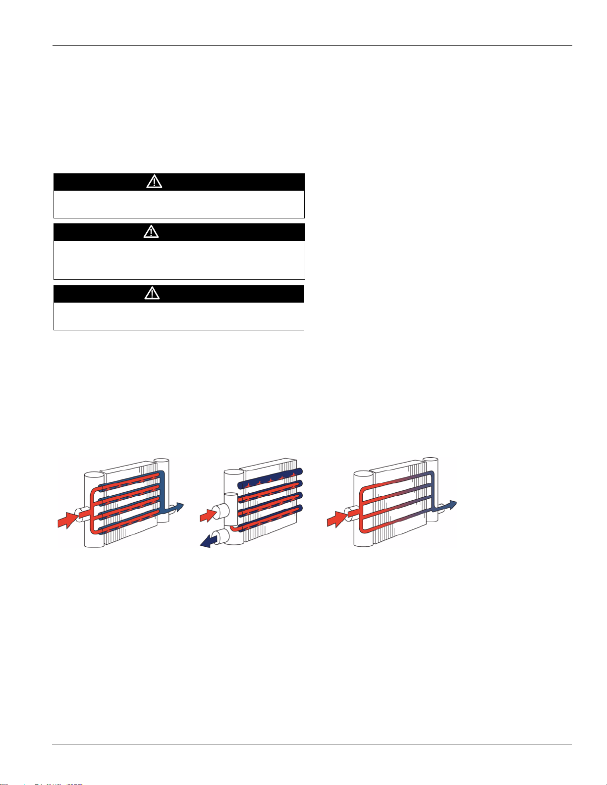
Coil Types
Distributing
McQuay models JA, RA and DA jet-tube steam distributing
coils (Figure 1) are excellent for any general purpose heating
application. With the superior freeze resistance provided by
the tube-with-in-a-tube construction, it is ideal for low
temperature preheating and special process applications. The
construction features inner tubes with directional orifices to
aid in steam distribution and condensate removal. Model JA
offers same-end supply and return connections. Model RA
offers opposite-end supply and return connections. Model DA
offers dual-supply opposite-end connections for long coils that
see sub-freezing air temperatures. Models GA, TA and LA
utilize cupro-nickel, carbon steel and stainless steel tubing for
high-pressure construction.
Single Tube
Receiving Instructions
1 Coils should be inspected for shipping damage upon
receipt. The freight bill should also be checked against
items received for complete delivery.
2 Damaged and/or missing items should be noted on the
carrier's freight bill and signed by the driver.
Figure 1: Coil Types
5R 5T
5J 5G
McQuay model SA steam coils (Figure 1) are designed for
general purpose heating. The construction features a single
tube design with opposite-end supply and return connections.
A perforated baffle located directly behind the supply
connection insures proper steam distribution. Model HA
utilizes cupro-nickel, carbon steel and stainless steel tubing for
high-pressure construction.
5S 5H
McQuay IM 901 3
Page 5
Introduction
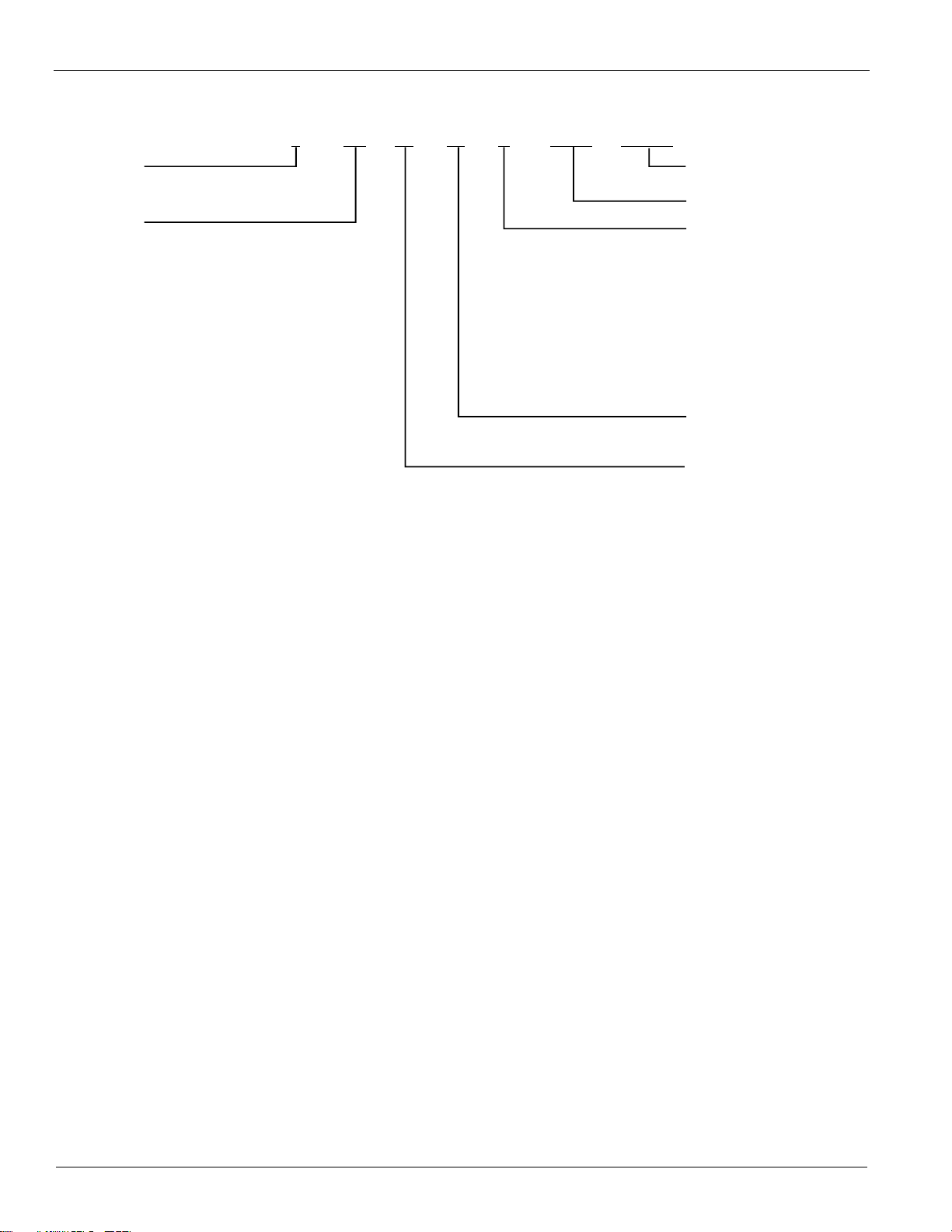
Nomenclature
5 SA 12 01 C 24.00 x 110.00
Tube O.D.
8=1"
5=5/8"
Coil Type
5SA: single tube, opposite end connection
5JA, 8JA: distributing tube, same end connection
5DA, 8DA: distributing tube, dual supply,
opposite end connection
8RA:
5HA: high-pressure construction single tube,
opposite end connection
5GA, 8GA: high-pressure construction distributing
tube, same end connection
5LA, 8LA: high-pressure construction
opposite end connection
8TA: high-pressure construction distributing tube,
opposite end connection
5SB: single tube, 3" center to center
opposite end connection
distributing tube, opposite end connection
dual supply,
Finned Length (inches)
Finned Heigth (inches)
Fin Design
A - flat (AI, Cu)
B - corrugated (AI, Cu)
C - sine wave (AI, Cu)
F - flat (SS, CS)
G - corrugated (SS, CU)
H - sine wave (SS, CU)
Rows Deep
Fins Per Inch
4 McQuay IM 901
Page 6

Installation
Mounting
Installation
Installation
Steam coils must be properly mounted for condensate removal.
This will aid in preventing destructive water hammer, keeping
coils from freezing and preventing corrosive elements from
collecting in the tubes. Case-pitched coils (Figure 2) should be
installed level. McQuay models SA, SB, HA, JA, GA, DA,
LA, RA and TA come standard pitched in the casing.
Coils that are un-pitched (Figure 3) must be installed with the
tubes pitched towards the return connection. A minimum pitch
of 1/8” per foot of coil length is required (pitch has been
exaggerated in Figure 3). Coils with opposite end connections
(RA, TA, SA, & HA) should be furnished with an expansion
joint or provisions made for expansion on opposite connection
end.
Figure 2: Case Pitched
Figure 3: Case Unpitched
WARNI NG
Steam, even at low pressure, can cause serious bodily injury
that may result in death. Be sure the system is off or the
components are isolated before beginning work..
CAUTION
Sharp edges on sheet metal and fasteners can cause
personal injury. This equipment must be installed, operated,
and serviced only by an experienced installation company and
fully trained personnel.
Protective equipment such as safety glasses, steel toe boots
and gloves are recommended during the installation and
routine maintenance of the coil.
CAUTION
Failure to properly install the coil can result in irreparable
damage to the coil as well as other components in the system.
If you are unsure about any portion of the installation, contact
your local steam specialist for assistance.
1 Carefully remove the coil from the shipping package to
avoid damage to the finned surface area. Damaged fins can
be straightened using an appropriate fin comb.
2 McQuay recommends cleaning the coil with a
commercially available coil cleaner prior to installation.
Refer to “Operation and Maintenance” on page 8 for
cleaning recommendations.
Note: Vacuum breakers and air vents should be piped to a
drain or other suitable location where discharged
steam cannot lead to personal injury.
3 Mount coil properly to provide positive condensate
drainage. Refer to “Mounting” on this page.
4 Proper clearance should be maintained between the coil
and other structures such as the fan, filter racks, transition
areas, etc.
5 Utilize vacuum breakers on each coil. Steam traps require a
positive pressure differential to force the condensate
through the valve seat. If the coil's pressure drops below
atmospheric, the pressure differential across the valve will
be negative and the condensate will not drain. This
condition can lead to serious damage or failure of the coil
due to freezing, water hammer and corrosion. Refer to
Figure 4 and Figure 5 for recommended placement.
McQuay IM 901 5
Page 7

Installation
Figure 4: Low Pressure Steam Coil Piping Diagram
SYMBOLS FOR PIPING ARRANGEMENTS
LOW PRESSURE (TO 25 PSI)
*5SA coil installed for vertical airflow. Installer
must pitch coil toward the return connection on
vertical airflow installations. For horizontal airflow installation, the required pitch is built into
the casing.
* NOTE: Rating data is ARI certified only for the
standard ARI coil orientation; i.e., horizontal
tubes, vertical coil face and horizontal airflow.
*5JA or 8JA coil installed with tubes vertical.
The coil supply piping must be dripped ahead of
the coil on an installation of this type.
5JA or 8JA coil installed in
series. Note that each coil
must have a separate control
valve and trap.
8RA and 5SA coils banked three high by
three deep. Individual trapping of each coil
as shown is preferred. Note that it is necessary to provide a separate control valve
for each bank in the direction of airflow.
*5SA coils installed with tubes vertical. Diagram
shows single trap; however, it is always preferable
to trap each coil individually.
* NOTE: Rating data is ARI certified only for standard ARI coil orientation; i.e., horizontal tubes,
vertical coil face and horizontal airflow.
6 McQuay IM 901
Page 8

Figure 5: High Pressure Steam Coil Piping Diagram
SYMBOLS FOR PIPING ARRANGEMENTS
HIGH PRESSURE (OVER 25 PSI)
Installation
5GA or 8GA coils. Note the addition of a vacuum
breaker to permit the coil to drain during shutdown.
Trap each coil separately. Differences in pressure from coil
6
to coil can result in the backing-up of condensate that will
result in poor coil performance and possible damage.
7 Provide an air vent for each coil at its highest location.
Non-condensable gasses present in the steam will collect in
a coil and reduce its capacity. Therefore, it is necessary to
provide a means for the removal of these gasses. Also,
these gasses can diffuse into the condensate forming biproducts, which can lead to severe corrosion.
8 Steam supply lines need to be drained of condensate. This
can be accomplished by the use of drip legs. This ensures
that high quality steam enters the coil.
9 Condensate return piping should be the same size as the
coil's return connection from the coil outlet to the steam
trap.
10 Once installed, the coil should be pressurized to 100 psig
with dry nitrogen or other suitable gas. The coil should be
left pressurized for a minimum of 10 minutes. If the coil
holds the pressure, the hook-up can be considered leak free.
If the pressure drops by 5 psig or less, re-pressurize the coil
and wait another 10 minutes. If the pressure drops again,
8TA or 5HA coils. Condensate is lifted to overhead return main.
there are more than likely one or more small leaks, which
should be located and repaired. Pressure losses greater than
5 psig would indicate a larger leak, which should be
isolated and repaired. Be sure to check valves and fittings
as potential sites for leakage or bleed. If the coil itself is
found to be leaking, contact your local McQuay
representative.
Note: Unauthorized repair to the coil may void the coil's
warranty (see McQuay’s warranty policy on back
cover).
11 All field brazing and welding should be performed using
high quality materials and an inert gas purge (such as
nitrogen) to reduce oxidation of the internal surface of the
coil.
12 All field piping must be self-supporting. System piping
should be flexible enough to allow for thermal expansion
and contraction of the coil. The use of flexible connections
and/or swing joints is recommended.
13 The coil along with the control valve and trap should be
isolated by manual valves to allow for servicing.
McQuay IM 901 7
Page 9

Operation and Maintenance
Operation and Maintenance
Operation
General
1 Proper air distribution is vital to coil performance. Airflow
anywhere on the coil face should not vary by more than
20%.
2 Air velocities should be maintained within McQuay’s
recommended values of between 200 and 1500 fpm.
3 Operating pressures must be at or below the maximum
operating pressure for that coil at the steam temperature.
Operating pressure maximum is 150 psig @ 300 F for low
pressure steam coils and 350 psig @ 450 F for high
pressure steam coils.
Maintenance
DANGER
Follow the manufacturer’s guidelines for lockout/tagout and
disconnect all power to the unit before performing maintenance.
Contact with high voltage power will cause electrical shock,
resulting in severe personal injury or death.
WARNING
Moving parts, high pressure, and/or high temperature fluids can
cause serious personal injury.
General
1 Filters should be inspected on a regular basis and changed
as needed. Clean filters help maintain maximum coil
performance and service life.
2 Periodic inspection of the coil for signs of corrosion and/or
leaks is recommended. Repair and replacement of the coil
and the connecting piping, valves, etc., should be
performed as needed by a qualified individual.
3 Should the coil surface need cleaning, caution should be
exercised in selecting the cleaning solution as well as the
cleaning equipment. Improper selection can result in
damage to the coil and/or health hazards.
4 Suggested cleaning instructions:
a When handling strong chemicals, be sure to wear
chemical impervious gloves, apron and splash goggles.
b Acti-Brite (AB-1) is the recommended cleaning
solution. Contact your local McQuay Parts Distributor.
CAUTION
Carefully read and follow the manufacturer's recommendations
before using any cleaning fluid.
c Determine required dilution for the specific application.
It is recommended to start with a dilution ratio of 10:1
and increase concentration until the desired results are
achieved.
d As with mixing all acids, place the desired amount of
water into the tank and then add the chemicals.
e Turn off fans and allow hot coils to cool before
applying.
f Using plain water, wet both the coil as well as the area
surrounding the equipment. Wetting the coil with water
aids in product penetration and performance.
g Apply properly diluted product to coil surface.
whenever possible, apply solution from the outlet side
of the coil. Allow solution to remain on surface,
normally 5-10 minutes. Do not allow solution to dry on
the coil.
Note: Note; In extreme cases, application may have to be
repeated to achieve desired results.
h If foaming does not occur, check for extreme grease
buildup which will slow cleaning process. Foaming may
not occur if coil is coated or painted.
i Rinse coils, tools and surrounding area thoroughly after
the coil cleaning.
j Clean the coil from the leaving airside so that foreign
material will be washed out of the coil rather than
pushed further in.
5 Internal coil maintenance consists of preventing scale and
corrosion. This is accomplished through aggressive boiler
water treatment, removal of dissolved oxygen and the
removal of non-condensable gasses such as carbon dioxide.
Note: Boiler water treatment is beyond the scope of this
manual. Contact your local water treatment
specialist for assistance in establishing a proper
boiler-water treatment program.
8 McQuay IM 901
Page 10

McQuay Training and Development
Now that you have made an investment in modern, efficient McQuay equipment, its care should be a high priority.
For training information on all McQuay HVAC products, please visit us at www.mcquay.com and click on training, or
call 540-248-9646 and ask for the Training Department.
Warranty
All McQuay equipment is sold pursuant to its standard terms and conditions of sale, including Limited Product
Warranty. Consult your local McQuay Representative for warranty details. Refer to Form 933-43285Y. To find your
local McQuay Representative, go to www.mcquay.com.
This document contains the most current product information as of this printing. For the most up-to-date product
information, please go to www.mcquay.com.
© 2008 McQuay International • www.mcquay.com • 800-432-1342
Page 11
LIMITED PRODUCT WARRANTY
(North America)
McQuay International (“Company”) warrants to contractor, purchaser and any owner of the product (collectively “Owner”) that
Company, at its option, will repair or replace defective parts in the event any product manufactured by Company, including products
sold under the brand names McQuay Air Conditioning, AAF Air Conditioning, AAF HermanNelson and McQuay Factory Service,
and used in the United States o r Canada, proves d efective in material or workmanship within twelve (12) months from initial startup
or eighteen (18) months from the date shipped by Company, whichever occurs first. Authorized replaced parts are warranted for the
duration of the original warranty. All shipments of such parts will b e made FOB factory, freight prepaid and allowed. Company
reserves the right to select carrier and method of shipment.
In addition, labor to repair or replace warranty parts is provided during Company normal working hours on products with rotary
screw compressors, centrifugal compressors and on absorption chillers. Warranty labor is not provided for any other products.
Company’s liability to Owner under this warranty shall not exceed the lesser of the cost of correcting defects in the products sold or
the original purchase price of the products.
PRODUCT STARTUP ON ABSORPTION, CENTRIFUGAL AND SCREW COMPRESSOR PRODUCTS IS MANDATORY and
must be performed by McQuay Factory Service or a Company authorized service representative.
It is Owner’s responsibility to complete and return the Registration and Startup Forms accompanying the product to Company within
ten (10) days of original startup. If this is not done, the ship date and the startup date will be deemed the same for warranty period
determination, and this warranty shall expire twelve (12) months from that date.
EXCEPTIONS
1. If free warranty labor is available as set forth above, such free labor does not include diagnostic visits, inspections, travel time
and related expenses, or unusual access time or costs required by product location.
2. Refrigerants, fluids, oils and expendable items such as filters are not covered by this warranty.
3. This warranty shall not apply to products or parts which (a) have been opened, disassembled, repaired, or altered by anyone other
than Company or its authorized service representative; or (b) have been subjected to misuse, negligence, accidents, damage, or
abnormal use or service; or (c) have been operated, installed, or startup has been provided in a manner contrary to Company’s
printed instructions; or (d) were manufactured or furnished by others and which are not an integral part of a product
manufactured by Company; (e) have been exposed to contaminates, or corrosive agents, chemicals, or minerals, from the water
supply source; or (f) have not been fully paid for by Owner.
ASSISTANCE
To obtain assistance or information regarding this warranty, please contact your local sales representative or McQuay Factory Service
office.
SOLE REMEDY
THIS WARRANTY CONSTITUTES THE OWNER’S SOLE REMEDY. IT IS GIVEN IN LIEU OF ALL OTHER
WARRANTIES. THERE IS NO IMPLIED WARRANTY OF MERCHANTABILITY OR FITNESS FOR A PARTICULAR
PURPOSE. IN NO EVENT AND UNDER NO CIRCUMSTANCE SHALL COMPANY BE LIABLE FOR INCIDENTAL,
INDIRECT, SPECIAL, CONTINGENT OR CONSEQUENTIAL DAMAGES, WHETHER THE THEORY BE BREACH OF
THIS OR ANY OTHER WARRANTY, NEGLIGENCE OR STRICT LIABILITY IN TORT.
No person (including any agent, sales representative, dealer or distributor) has the authority to expand the Company’s obligation
beyond the terms of this express warranty or to state that the performance of the product is other than that published by Company.
For additional consideration, Company will provide an extended warranty(ies) on certain products or components thereof. The terms
of the extended warranty(ies) are shown on a separate extended warranty statement.
Form No. 933-430285Y-00-D (2/03, 10/05, 11/08)
 Loading...