

Page 1
Installation and Maintenance Manual IM-803
Group: Unitary
Part Number: IM-803
Date: August 2005
Supersedes: March 2005
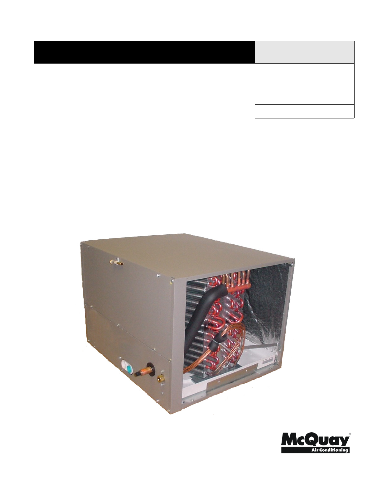
HCC Cased Horizontal “A” Indoor Coil
2 to 5 Ton
© 2005 McQuay International
IM-803 Page 1
Page 2

Table of Contents
M
H
g
A
MODEL NOMENCLATURE . . . . . . . . . . . . . . . . . . . . . . . . . 2
INTRODUCTION . . . . . . . . . . . . . . . . . . . . . . . . . . . . . . . . . 2
General Description. . . . . . . . . . . . . . . . . . . . . . . . . . . . . . . 2
Receiving Inspection . . . . . . . . . . . . . . . . . . . . . . . . . . . . . . 2
Codes and Regulations . . . . . . . . . . . . . . . . . . . . . . . . . . . . 2
Important Message to the Installer . . . . . . . . . . . . . . . . . . . 3
Important Message to the Owner . . . . . . . . . . . . . . . . . . . . . 3
Replacement Parts . . . . . . . . . . . . . . . . . . . . . . . . . . . . . . . . 3
GENERAL WARNINGS . . . . . . . . . . . . . . . . . . . . . . . . . . . . 3
APPLICATION INFORMATION . . . . . . . . . . . . . . . . . . . . . . 3
Special Instructions . . . . . . . . . . . . . . . . . . . . . . . . . . . . . . . . 3
Thermal Expansion Valve . . . . . . . . . . . . . . . . . . . . . . . . . . . 4
PLASTIC DRAIN PAN APPLICATION . . . . . . . . . . . . . . . . . 4
MODEL NOMENCLATURE
"McQuay" is a registered trademark of McQuay International.
"Illustrations and information cover the McQuay International products
at the time of publication and we reserve the right to make changes in
design and construction at any time without notice."
© 2005 McQuay International
odel
CC = Horizontal Cased Coil
Nominal Capacity (tons)
24 = 2
30 = 2-1/2
36 = 3
42 = 3-1/2
48 = 4
60 = 5
*Field mounted Thermal Expansion Valve is available as an accessory.
Table 1: Unit Nameplate Model Number Identifier
Unit Nameplate McQuay Model Number
CHPF024A2A HCC024AAFY
CHPF030A2A HCC030AAFY
CHPF036B2A HCC036ABFY
CHPF042B2A HCC042ABFY
CHPF048D2A HCC048ACFY
CHPF060D2A HCC060ACFY
HCC 024
AFY
Future Use
Refrigerant Meterin
F = Flowrater*
Cabinet Heigth
A = 14"
B = 17-1/2"
C = 24-1/2"
Vintage
INTRODUCTION
General Description
These installation instructions cover the indoor installation of
cased horizontal “A” indoor coils, sizes 2 to 5 tons. See the
product catalog applicable to your model for information
regarding specifications applicable to your model and accessories.
Receiving Inspection
McQuay products are carefully inspected prior to shipment
and the carrier has assumed responsibility for loss or damage
upon acceptance of the shipment.
Upon receiving your shipment, check all items carefully
against the Bill of Lading. Inspect the unit and/or accessories
for shipping damage as soon as they are received. Immediately file claims for loss or damage, either shipping or concealed, with the shipping company.
Page 2 IM-803
Check the unit nameplate to verify the model number and electrical characteristics are correct. In the event an incorrect unit
is shipped, it must be returned to the supplier and must NOT
be installed. The manufacturer disclaims all responsibility for
the installation of incorrectly shipped units.
Codes and Regulations
This product is designed and manufactured to permit installation in accordance with National Codes. System design
should, where applicable, follow information presented in
accepted industry guides such as the ASHRAE Handbooks. It
is the installer' s responsibility to install the product in accordance with National Codes and/or prevailing local codes and
regulations. The manufacturer disclaims all responsibility for
equipment installed in violation of any code or regulations
Page 3

.
IMPORTANT
The United States Environmental Protection Agency
(EPA) regulations cover introduction and disposal of
refrigerants in this unit. Failure to follow those
regulations can harm the environment and lead to
substantial fines. Because regulations can change over
time, a certified technician should perform any work
done on this unit. If you have any questions, please
contact the local office of the EPA.
Important Message to the Installer
This equipment is to be installed by an experienced installation
company and fully trained personnel. Carefully read all
instructions and take into account any special considerations
prior to installing the unit. Give this manual to the owner and
explain its provisions.
Important Message to the Owner
Read these instructions carefully and keep them near the product for future reference. Although these instructions are
addressed primarily to the installer, useful maintenance information is included. Have the installer acquaint you with the
operation of the product and periodic maintenance requirements.Recognize Safety Symbols, Words, and Labels
The following symbols and labels are used throughout this
manual to indicate immediate or potential hazards. It is the
owner's and installer's responsibility to read and comply with
all safety information and instructions accompanying these
symbols. Failure to heed safety information increases the risk
of property damage and/or product damage, serious personal
injury or death. Improper installation, operation and maintenance can void the warranty.
GENERAL WARNINGS
CCAUTION
Read these instructions before performing this
installation or servicing this unit. All installations must
be in accordance with all national, state, or local
building codes.
APPLICATION INFORMATION
1. Coil must be installed upstream (on the discharge air side)
of the furnace.
2. Condensate Drain Piping - In all cooling applications, the
installer should provide a secondary drain pan. Place the
pan under the entire unit with a separate drain line properly sloped and terminated in an area visible to the owner.
This secondary drain pan can provide an added drain trap
in the area under the unit in the event the primary drain
plugs up and overflows. McQuay will not be liable for
any damages, structural or otherwise due to the failure to
follow this installation requirement.
Condensate drain connections are located in the drain pan at
the bottom of the coil/enclosure assembly. The threaded fitting
protrudes outside of the enclosure for connecting externally.
1. The drain hole in the drain pan must be clear.
2. Insulate the drain line to prevent sweating and dripping.
Use armaflex or similar material.
A Secondary Condensate Drain Connection, now called for by
many building codes, has been provided. Pitch the drain line
1/4" per foot to provide free drainage. Install a condensate trap
to provide proper drainage.
DANGER
Immediate hazards which WILL result in property
damage, product damage, severe personal injury and/
or death.
WARNING
Hazards or unsafe practice CAN result in property
damage, product damage, sever personal injury and/or
death.
CAUTION
Hazards or unsafe practices which CAN result in
property damage, product damage, and/or personal
injury.
Replacement Parts
Replacement parts can be obtained by contacting McQuay at
1
-800-37-PARTS. When contacting McQuay for service or
replacement parts, refer to the model number and serial number of the unit as stamped on the nameplate attached to the
unit.
Note: If a secondary drain is not installed, the second-
ary access must be plugged.
Special Instructions
This indoor coil contains the flowrater distributor assembly,
which consists of a flare nut, distributor body, copper tubes
feeding the coil, and the internal flow check piston. It is essential that the indoor and outdoor sections be properly matched.
When matching the indoor coil with other than the matching
outdoor section, the flow check piston in the indoor section
should be changed to match the outdoor section to obtain rated
performance as specified in our product catalog. (See Piston
Kit Chart ).
A piston size that is too small will cause starving and one that
is too large will cause flooding. Change the piston in the distributor on the indoor coil before installing the coil and charging the system following the procedure shown below.
1. Using a back-up wrench on the flare fitting, remove the 3/
8" flare nut.
2. Using a back-up wrench on the distributor body, remove the
3/8" flare fitting and Teflon seal.
3. Using the wire provided with replacement pistons, run wire
(hooked end) through hole in piston.
4. Hook nose end of piston and lift gently from distributor
body.
IM-803 Page 3
Page 4

5. Referring to the Piston Kit Chart, replace piston with one of
proper size.
6. Install piston with Teflon seal end of piston in distributor
first. Do not force piston into distributor.
Note: With piston in distributor, seal end should be
down and should not be seen looking in end of
distributor. Piston must be free to rotate and
move up and down. Make sure piston is free to
move in distributor body.
7. Replace 3/8" flare fitting with Teflon seal using back-up
wrench on distributor body. Torque fitting with 8 to 10 ft.
lb. Do not over tighten.
8. Replace 3/8" flare nut using back-up wrench on flare fitting.
Torque 3/8" flare nut with 40 to 45 ft. lb.
9. Remove old piston size label from outside of distributor
body.
10. Remove new piston size label from the poly bag the new
piston came in and install new size label on outside of distributor.
11. Check fittings for leaks after installation, and make sure
evacuation and charging of low side are complete.
Thermal Expansion Valve
The TXV bulb is supplied as an optional accessory. To prevent
damage, remove the bulb when welding and attach/insulate to
the suction line after welding. For the majority of installations,
no adjustment to the TXV setting is required. However, if the
measured superheat is less than 8° or greater than 20° an
adjustment is required. The adjustment stem is at the base of
the valve (opposite the diaphragm) under a flair nut. To
increase the superheat when measured at the condenser base
valve, turn the stem clockwise (3). Similarly to decrease the
superheat, turn the stem counterclockwise (4). Use a ¼”
refrigeration wrench for this function.
NOTE FOR QUICK CONNECT COILS INSTALLATION
OF PRECHARGED SYSTEM
A brief description follows, for specific instructions refer to
the Condensing Unit’s Installation and Operating Instructions.
C. Check to be sure mating surfaces are clean.
D. Lubricate rubber seal with clean refrigerant oil and
thread couplings together by hand to be sure they are
not cross threaded.
E. Tighten connections using backup wrench on evapora-
tor quick connect fitting until coupling bottoms; then
tighten 1/6 turn to complete knife edge seal.
2. Connect lines to condensing unit in the same manner as
to evaporator coil. Observe same precautions.
3. After making all connections and opening valves, check
all piping for leaks.
PLASTIC DRAIN PAN APPLICATION
CCAUTION
DO NOT USE THIS COIL ON ANY APPLICATIONS
WHERE THE TEMPERATURE OF THE DRAIN PAN
MAY EXCEED 300°F. USE A FIELD-FABRICATED
METAL DRAIN PAN FOR THESE TYPES OF
APPLICATIONS.
Do not use a low temperature material in a high temperature
application. Strictly adhere to these instructions.
The drain pan has a primary and an optional secondary drain
with 3/4" NPT female connections. The connectors required
can be 3/4" NPT male PVC pipe or metal. Do not over torque,
or drain pan connection will be damaged. If secondary drain
line is required it must be run separately from the primary
drain and should end where it is easily seen. Water coming
from this line means the coil primary drain is plugged and
needs clearing.
A trap must be installed in the drain line below the bottom of
the drain pan. If a copper drain line is used, solder a short piece
of pipe to connector before installing a drain fitting. Again do
not over torque the 3/4" copper connector to the plastic drain
connection. Use a wet rag or heat sink material on the short
piece to protect plastic drain pan, when completing drain line.
Refer to Figure 1.
Figure 1. Condensate Drain Installation
1. Connect lines to evaporator coil before connecting to the
condensing units.
A. Form tubing so it properly aligns with coil connec-
tions.
B. Remove plugs and caps from connections.
This document contains the most current product information as of this printing. For the most up-to-date
product information, please go to www.mcquay.com.
www.mcquay.com • 800-432-1342
Page 4 IM-803
 Loading...