

Page 1
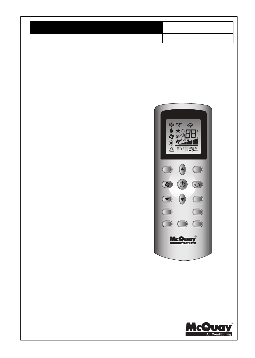
OPERATION MANUAL
OM-GS01-1209(0)-McQuay
Part Number: R08019034087
TURBO QUIET
SLEEP
ON OFF
CANCEL
TIMER
CLOCK
MODE
CANCEL
Before using your air conditioner, please read this operating manual carefully and keep it
for future reference.
Page 2

Page 3

GS01 Remote Control Indication / Indication De
Télécommande GS01 / GS01-Fernbedienungsanzeige /
Indicazioni Telecomando GS01 / Indicación Del Mando A
Distancia GS01 / Индикация пульта
дистанционного управления GS01 /
Kumanda GöstergeleriKumanda Göstergeleri
Kumanda Göstergeleri
Kumanda GöstergeleriKumanda Göstergeleri
GS01 UzaktanGS01 Uzaktan
GS01 Uzaktan
GS01 UzaktanGS01 Uzaktan
1
2
12
11
TURBO QUIET
7
13
9
3
4
SLEEP
ON OFF
CANCEL
TIMER
CLOCK
MODE
CANCEL
6
5
8
10
i
Page 4
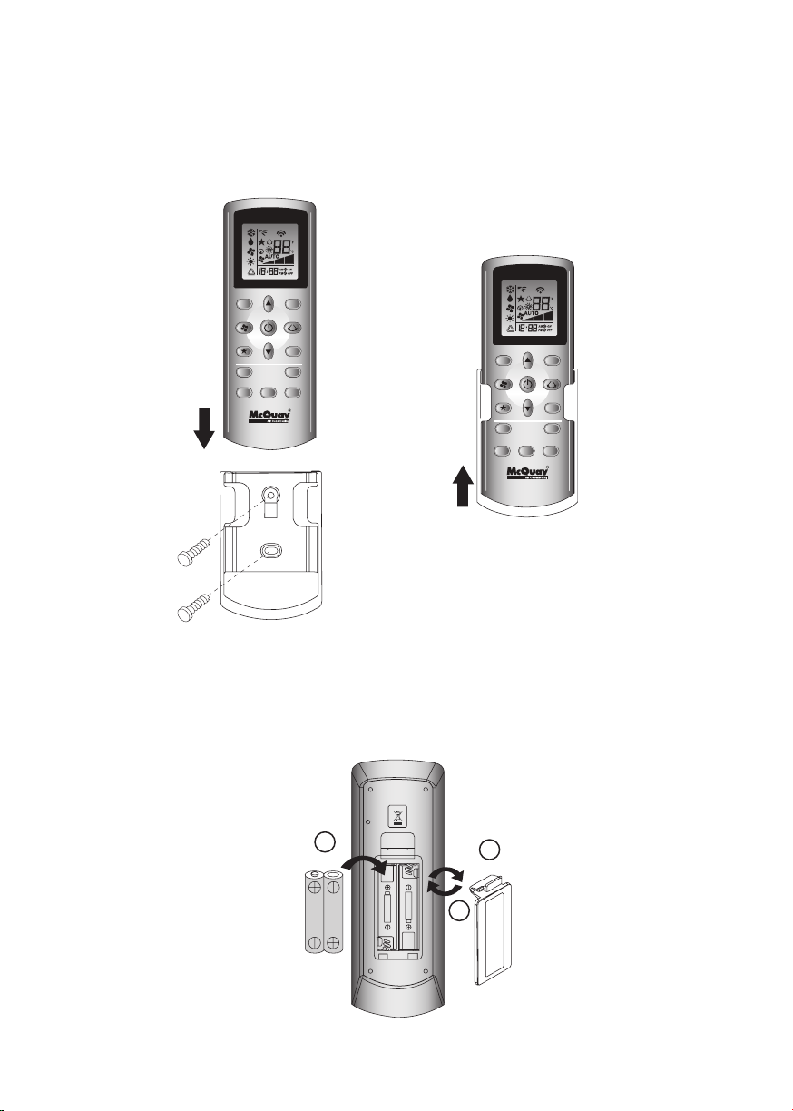
HOW TO MOUNT ONTO THE WALL / COMMENT INSTALLER SUR LE MUR /
ANBRINGEN DER FERNSTEUERUNG AN DER WAND /
COME FISSARE L’ASTUCCIO DEL TELECOMANDO ALLA PARETE /
MONTAJE SOBRE LA PARED / КАК УСТАНОВИТЬ НА СТЕНУ /
DUVARA NASIL YERLEfiT‹R‹L‹RDUVARA NASIL YERLEfiT‹R‹L‹R
DUVARA NASIL YERLEfiT‹R‹L‹R
DUVARA NASIL YERLEfiT‹R‹L‹RDUVARA NASIL YERLEfiT‹R‹L‹R
TURBO QUIET
SLEEP
TIMER
ON OFF
CLOCK
CANCEL
MODE
CANCEL
TURBO QUIET
SLEEP
TIMER
ON OFF
CLOCK
CANCEL
MODE
CANCEL
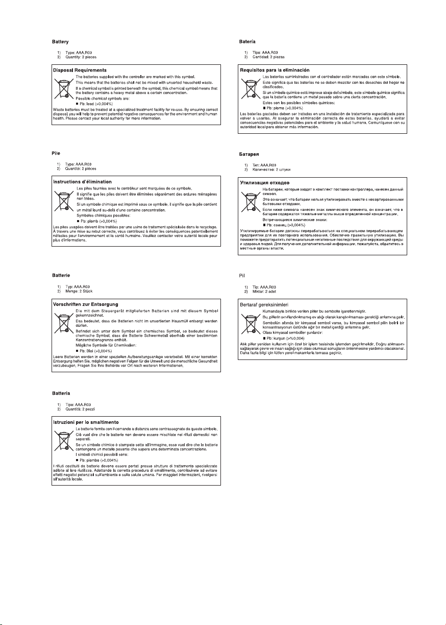
TO INSERT BATTERIES (AAA.R03) / INTRODUIRE LES PILES (AAA.R03) /
EINSETZEN DER BATTERIEN (AAA.R03)/ INSERIMENTO DELLE BATTERIE
(AAA.R03) / INSERTE LAS PILAS (AAA.R03) / УСТАНОВКА БАТАРЕЙ
(AAA.R03) /
P‹LLER NASIL TAKILIR (AAA.R03)P‹LLER NASIL TAKILIR (AAA.R03)
P‹LLER NASIL TAKILIR (AAA.R03)
P‹LLER NASIL TAKILIR (AAA.R03)P‹LLER NASIL TAKILIR (AAA.R03)
2
1
R03 / AAA 1.5V
R03 / AAA 1.5V
ii
3
Remove batteries if the air conditioner
is not in use for a long period of time.
Use 2 "AAA" 1.5V Batteries.
Page 5

REMOTE CONTROLLER LOSS PREVENTION WITH BALL CHAIN (OPTIONAL) / PRÉVENTION
CONTRE LA PERTE DE LA TÉLÉCOMMANDE PAR CHAÎNETTE À BOULES (FACULTATIF) / DIE
FERNBEDIENUNG IST DURCH EINE KUGELKETTE VOR VERLUST GESICHERT (OPTIONAL) /
PREVENZIONE PERDITA TELECOMANDO CON CATENA A SFERA (OPZIONALE) /
PREVENCIÓN DE PÉRDIDA DEL CONTROL REMOTO CON CADENA DE BOLAS (OPCIONAL)
/ ПРЕДОТВРАЩЕНИЕ ПОТЕРИ ПДУ С ПОМОЩЬЮ ШАРИКОВОЙ ЦЕПИ
(ДОПОЛНИТЕЛЬНОЕ ОБОРУДОВАНИЕ) /
KAYBOLMASININ ÖNLENMES‹ (‹STE⁄E BA⁄LI)KAYBOLMASININ ÖNLENMES‹ (‹STE⁄E BA⁄LI)
KAYBOLMASININ ÖNLENMES‹ (‹STE⁄E BA⁄LI)
KAYBOLMASININ ÖNLENMES‹ (‹STE⁄E BA⁄LI)KAYBOLMASININ ÖNLENMES‹ (‹STE⁄E BA⁄LI)
Remote controller
Télécommande
Fernbedienung
Telecomando
Control Remoto
Пульт дистанционного
управления
Uzaktan kumanda
Z‹NC‹RLE UZAKTAN KUMANDANINZ‹NC‹RLE UZAKTAN KUMANDANIN
Z‹NC‹RLE UZAKTAN KUMANDANIN
Z‹NC‹RLE UZAKTAN KUMANDANINZ‹NC‹RLE UZAKTAN KUMANDANIN
Screw
Vis
Schraube
Vite
Tornillo
Винт
Vida
Wall attachment screw
Vis de fixation murale
Schraube für Wandbefestigung
Vite fissaggio a parete
Tornillo de instalación en pared
Винт настенного крепления
Duvar ba¤lant› vidas›
Holder
Support
Halterung
Supporto
Soporte
Держатель
Ball chain (350mm)
Chaînette à boules (350 mm)
Kugelkette (350mm)
Catena a sfera (350 mm)
Cadena de bolas (350mm)
Шариковая цепь (350 мм)
Zincir (350mm)
Tutucu
1. Installation
Match the ring at the end of the ball chain with the screw hole on the back of the
remote controller and secure it with the screw.
2. Attach the holder and the ball chain as above at the position where signals from
the remote controller can be received easily.
3. Pass the ball chain through the back of the holder and match the ring at the end of
the ball chain to the upper hole of the holder. Fix the holder to the wall by putting
through 2 screws across it.
iii
Page 6

1. Installation
Faites correspondre l’anneau de
l’extrémité de la chaînette à boules
avec le trou de vis situé au dos de la
télécommande et fixez-le à l’aide de
la vis.
2. Fixez le support et la chaînette à
boules comme ci-dessus, dans une
position permettant une réception
facile des signaux de la
télécommande.
3. Passez la chaînette à boules à l'arrière
du support et faites correspondre
l’anneau de l’extrémité de la
chaînette à boules avec le trou
supérieur du support. Fixez le
support au mur à l’aide de 2 vis.
1. Installation
Legen Sie den Ring am Ende der
Kugelkette auf die Schraubbohrung
an der Rückseite der Fernbedienung
und befestigen Sie ihn mit der
Schraube.
2. Montieren Sie die Halterung und die
Kugelkette wie oben gezeigt an der
Stelle, an der Signale von der
Fernbedienung gut empfangen
werden können.
3. Führen Sie die Kugelkette durch die
Rückseite der Halterung und legen
Sie den Ring am Kettenende auf das
obere Loch in der Halterung.
Befestigen Sie die Halterung mit 2
Schrauben an der Wand.
1. Installazione
Far combaciare l’anello all’estremità
della catena a sfera con il foro della
vite sul retro del telecomando e
fissare bene con la vite.
2. Fissare il supporto e la catena a sfera
al di sopra del punto in cui possono
essere ricevuti facilmente i segnali
dal telecomando.
3. Far passare la catena a sfera
attraverso il retro del supporto e far
combaciare l’anello all’estremità
della catena con il foro superiore del
supporto. Fissare il supporto alla
parete mettendo 2 viti attraverso di
esso.
1. Instalación
Una el anillo del final de la cadena
de bolas con el agujero del tornillo
de la parte trasera del control remoto
y fíjelo con el tornillo.
2. Coloque el soporte y la cadena de
bolas, como indica la imagen
superior, en una posición en que las
señales del control remoto se puedan
recibir con facilidad.
3. Pase la cadena de bolas por la parte
trasera del soporte y una el anillo del
final de la cadena de bolas con el
agujero superior del soporte. Fije el
soporte en la pared colocando 2
tornillos a través del soporte.
1. Монтаж
Соотнесите кольцо на конце
шариковой цепи с винтовым
отверстием в задней части
пульта дистанционного
управления и закрепите его с
помощью винта.
2. Прикрепите держатель и
шариковую цепь, как показано
выше, в положении, где
обеспечивается легкий прием
сигнала ПДУ.
3. Проденьте шариковую цепь
через заднюю часть
держателя и соотнесите
кольцо на конце шариковой
цепи с верхним отверстием
держателя. Прикрепите
держатель к стене с помощью
2 винтов.
MontajMontaj
1.
Montaj
MontajMontaj
Zincirin sonundaki halkayla
uzaktan kumandan›n arkas›ndaki
vida deli¤ini efllefltirin ve vidayla
sabitleyin.
2. Tutucu ve zinciri uzaktan
kumandadan gelen sinyallerin
kolayca al›nabilece¤i yerin
üzerine yerlefltirin.
3. Zinciri tutucunun arkas›ndan
geçirin ve zincirin sonundaki
halkay› tutucunun üst deli¤i ile
efllefltirin. Tutucuyu her iki viday›
içinden geçirerek duvara
sabitleyin.
iv
Page 7
v
Page 8

OPERATING GUIDE
1. Transmission source
• The source where the signal will be transmitted.
2. Signal transmission indication
• Blink to confirm that the last setting has been transmitted to the unit.
3. “ON/OFF” Button
• Press once to start the air conditioner unit.
• Press again to stop the unit.
4. Fan speed selection
• Press the button continuously will toggle the fan speed in the following
order:
Low –––: Med –––: High –––: Auto
• Stop pressing when the desired fan speed appears on the display screen.
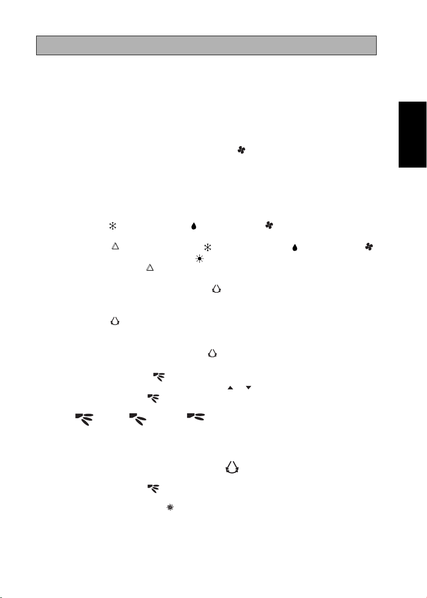
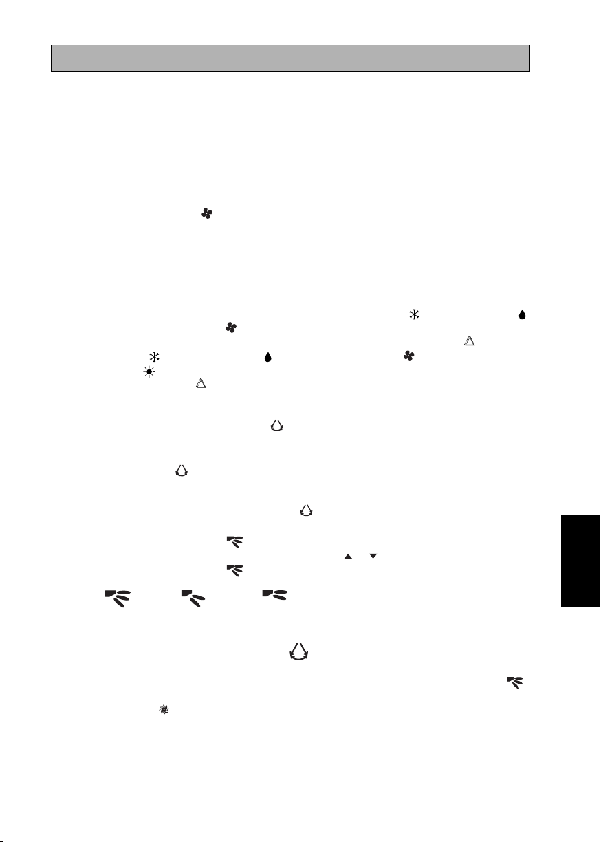
5. Operation mode
• Press the MODE button to select the type of operating mode.
• For cooling only unit, the available modes are: COOL ( ), DRY ( ) and
FAN ( ).
• For heat pump unit, the available modes are: AUTO ( ), COOL ( ),
DRY ( ), FAN ( ) and HEAT ( ).
• The AUTO ( ) mode is unavailable for chilled water system.
6. Automatic air swing
• Press the SWING button to activate the automatic air swing function.
• To distribute the air to a specific direction, press the SWING button and
wait until the louver move to the desired direction and press the button once
again.
Swing mode selection method (for CK-E model)
• Press SWING ( ) button for 4 seconds to enter field setting mode. While in
field setting mode, it will only show SWING MODE ( ).
• Press temperature and button to select SWING MODE ( ) rotation
from Swing Mode 1 to Swing Mode 3.
• There are 3 different SWING MODE, which are:
ENGLISH
Original Instruction
Swing mode 1 Swing mode 2 Swing mode 3
SWING MODE will not activate unless SWING is activated.
Swing is indicated by the logo:
• If no mode changes within 4 seconds, unit will operate according to the selected
SWING MODE ( ).
7. Turbo function (model dependent)
• Press for fast cooling or heating operation.
• Fan speed turn to maximum speed.
• Press again to deactivate the function.
• Available under HEAT, COOL and DRY modes only.
• Any change of fan speed will deactivate this function.
1
Page 9

• The Turbo function ( ) is unavailable for chilled water system and remote
control with SWING MODE ( ) function.
8. OFF timer setting
• Press the OFF TIMER CANCEL button will activate the off timer function.
• Set the desired off time by pressing the OFF TIMER CANCEL button
continuously.
• Press the CANCEL button to cancel the off timer setting.
9. Quiet function (model dependant)
• Press
for quiet operation.
• Fan speed turn to minimum speed.
• Press again to deactivate the function.
• Any change of fan speed will deactivate this function.
• The Silent function (
) is unavailable for chiller water system.
10. Clock time setting
• Press and hold button to set the clock time.
11. ON timer setting
• Press the ON TIMER CANCEL button will activate the on timer function.
• Set the desired on time by pressing the ON TIMER CANCEL button
continuously. If the timer is set to 7.30am, the air conditioner will turn on at
7.30am sharp.
• Press the CANCEL button to cancel the on timer setting.
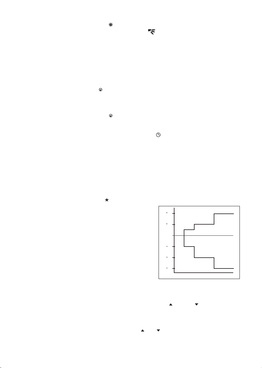
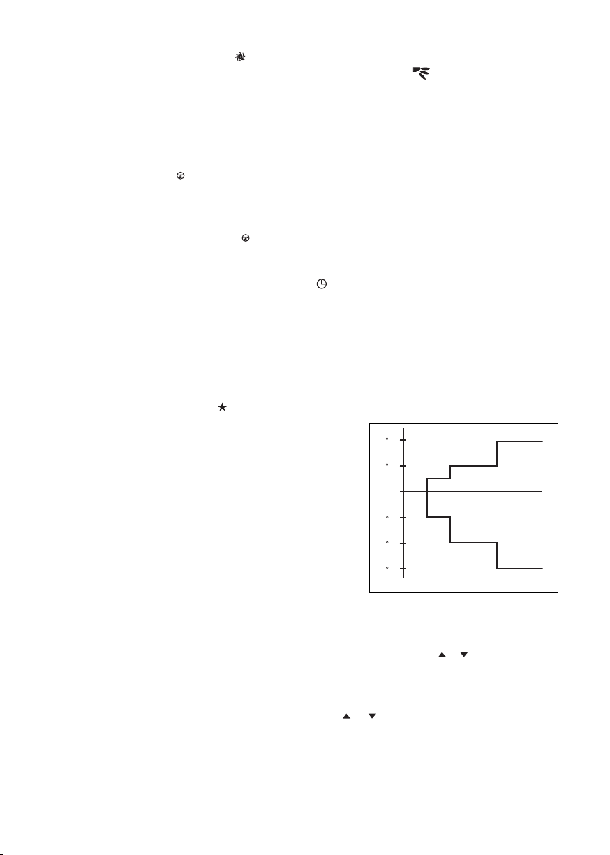
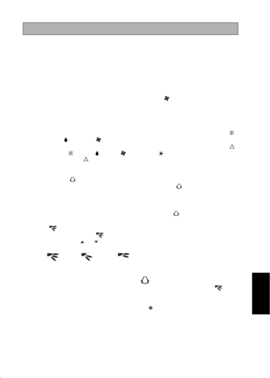
12. Sleep mode setting
• Press the button will activate the sleep mode function.
• This is an energy saving option. When the
unit is operating under cooling mode, the
set temperature is increased by 0.5°C after
the first half an hour, another 0.5°C after
+2 C
+1 C
the second half an hour and 1°C after the
following 1 hour.
• When the unit is operating under heating
mode, the set temperature is decreased by
- 1 C
- 2 C
1°C after the first half an hour, another 1°C
after the second half an hour and 1°C after
the following 1 hour.
- 3 C
0 0.5 1 1.5 2
• This function is available under COOL, HEAT and AUTO mode.
13. Temperature setting
• To set the desired room temperature, press the or button to increase or
decrease the set temperature.
• The temperature setting range is from 16°C to 30°C (Optional setting 20°C
to 30°C).
• Press both buttons and simultaneously to toggle from °C to °F setting.
2
Page 10

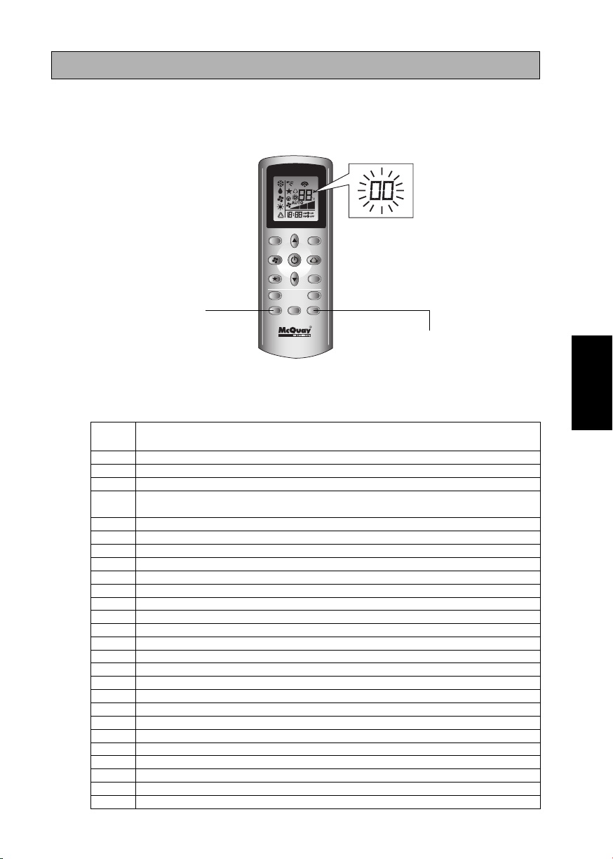
0000
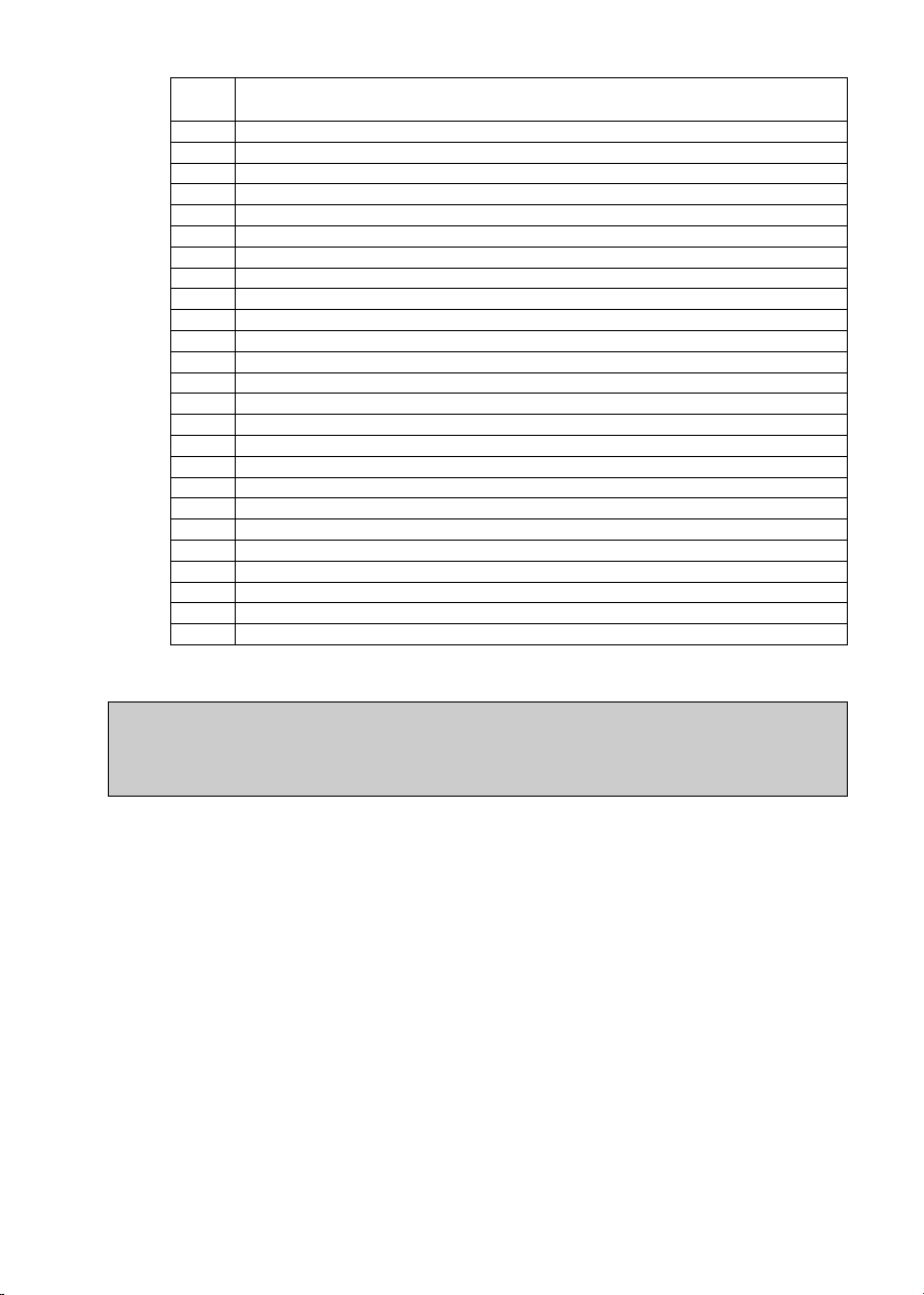
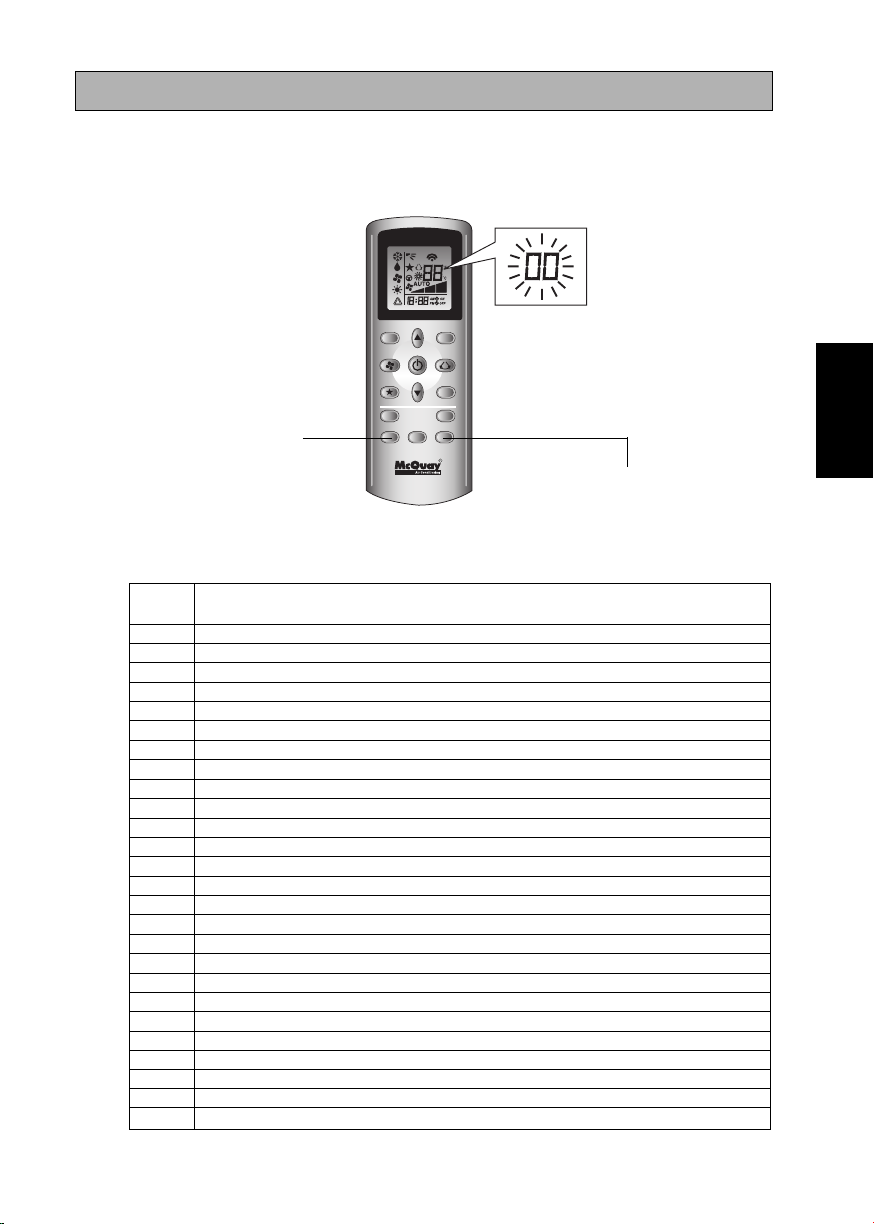
FAULT DIAGNOSIS (For Inverter only)
FAULT DIAGNOSIS BY REMOTE CONTROLLER
The temperature display sections indicate corresponding codes.
1. When the ON TIMER CANCEL button or OFF TIMER CANCEL button is held down for
5 seconds, a “
ON TIMER CANCEL
2. Press the ON TIMER CANCEL button or OFF TIMER CANCEL button repeatedly until a
continuous beep is produced.
• The code indication changes as shown below, and notifies with a long beep.
” indication flashes on the temperature display section.
TURBO QUIET
SLEEP
MODE
TIMER
ON OFF
CANCEL
CLOCK
CANCEL
OFF TIMER CANCEL
ENGLISH
ERROR
CODE
MEANING
00 NORMAL
A1 INDOOR PCB ERROR
A3 DRAIN PUMP ABNORMAL
A5 ANTIFREEZE (COOLING)/HEAT EXCHANGER OVERHEAT (HEATING)
A6 INDOOR FAN MOTOR ABNORMAL
AH ELECTRICAL AIR CLEANER ABNORMAL
C4 INDOOR HEAT EXCHANGER (1) THERMISTOR SHORT/OPEN
C5 INDOOR HEAT EXCHANGER (2) THERMISTOR SHORT/OPEN
C7 LOUVER LIMIT SWITCH ERROR
C9 INDOOR ROOM THERMISTOR SHORT/OPEN
E1 OUTDOOR PCB ERROR
E3 HIGH PRESSURE PROTECTION
E4 LOW PRESSURE PROTECTION
E5 COMPRESSOR MOTOR LOCK/COMPRESSOR OVERLOADED
E6 COMPRESSOR START-UP ERROR
E7 OUTDOOR DC FAN MOTOR LOCK
E8 AC INPUT OVER CURRENT
E9 EXV ERROR
EA 4 WAY VALVE ERROR
F3 DISCHARGE PIPE OVERHEAT
F6 HEAT EXCHANGER OVERHEAT
HO COMPRESSOR SENSOR SYSTEM ERROR
H3 HIGH PRESSURE SWITCH ERROR
H6 COMPRESSOR FEEDBACK DETECTION ERROR
H7 FAN MOTOR OVERLOADED/OVERCURRENT/SENSOR ABNORMAL
H8 AC CURRENT SENSOR ERROR
3
Page 11
ERROR MEANING
CODE
H9 OUTDOOR AIR THERMISTOR SHORT/OPEN
J1 PRESSURE SENSOR ERROR
J3 COMPRESSOR DISCHARGE PIPE THERMISTOR SHORT/OPEN/MISPLACED
J5 SUCTION PIPE THERMISTOR SHORT/OPEN
J6 OUTDOOR HEAT EXCHANGER THERMISTOR SHORT/OPEN
J7 SUBCOOLING HEAT EXCHANGER THERMISTOR SHORT/OPEN
J8 LIQUID PIPE THERMISTOR SHORT/OPEN
J9 GAS PIPE THERMISTOR SHORT/OPEN
L1 INVERTER OUTDOOR PCB ERROR
L3 OUTDOOR CONTROL BOX OVERHEAT
L4 HEAT SINK OVERHEAT
L5 IPM ERROR/IGBT ERROR
L8 INVERTER COMPRESSOR OVERCURRENT
L9 COMPRESSOR OVERCURRENT PREVENTION
LC COMMUNICATION ERROR (OUTDOOR CONTROL PCB AND INVERTER PCB)
P1 OPEN PHASE OR VOLTAGE UNBALANCE
P4 HEAT SINK THERMISTOR SHORT/OPEN
PJ CAPACITY SETTING ERROR
U0 INSUFFICIENT GAS
U2 DC VOLTAGE OUT OF RANGE
U4 COMMUNICATION ERROR
U7 COMMUNICATION ERROR (OUTDOOR CONTROL PCB AND IPM PCB)
UA INSTALLATION ERROR
UF PIPING & WIRING INSTALLATION MISMATCH/WRONG WIRING/INSUFFICIENT GAS
UH ANTIFREEZE (OTHER ROOMS)
NOTE
1. A short beep and two consecutive beeps indicate non-corresponding codes.
2. To cancel the code display, hold the ON TIMER CANCEL button or OFF TIMER CANCEL
button down for 5 seconds. The code display also cancel itself if the button is not pressed for
1 minute.
4
Page 12
MODE D’EMPLOI
1. Source de transmission
• La source d’où le signal sera transmis.
2. Indication de transmission de signal
• Clignotement pour confirmer que le dernier réglage ait été transmis à l’unité.
3. Bouton “ON/OFF” (MARCHE’/ARRÊT)
• Appuyez une fois pour mettre le climatiseur en marche.
• Appuyez de nouveau pour éteindre le climatisateur.
4. Sélection de la vitesse du ventilateur
• Appuyez de façon continue sur le bouton pour transformer successivement
la vitesse du ventilateur comme suit:
Lent –––: Moyen –––: Rapide –––: Auto
• Cessez d’appuyer lorsque la vitesse désirée apparaît sur l’écran d’affichage.
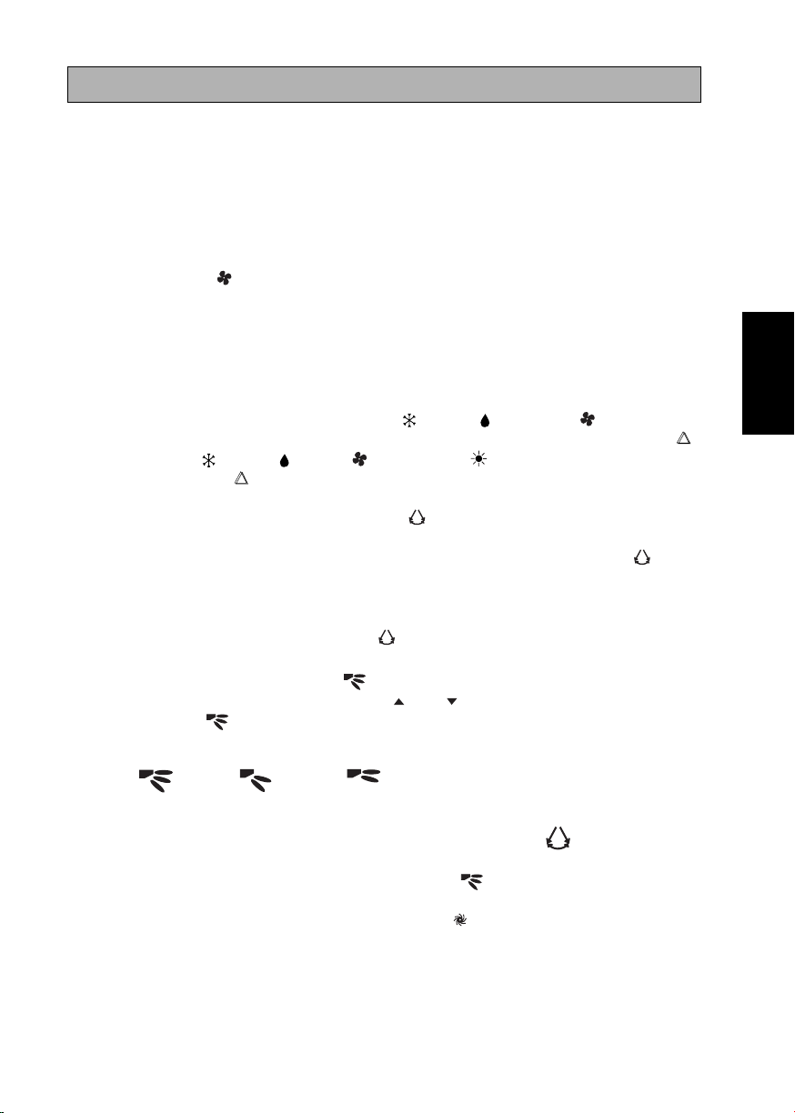
5. Mode opérationnel
• Appuyez sur le bouton MODE pour sélectionner le type de mode opérationnel.
• Pour l’unité de refroidissement, les modes disponibles comprennent
COOL ( ) (FROID), DRY ( ) (SEC) et FAN ( ) (VENTILATION).
• Pour l’unité de thermopompe, les modes disponibles comprennent:
AUTO ( ) (AUTO), COOL ( ) (FROID), DRY ( ) (SEC), FAN ( )
(VENTILATION) et HEAT ( ) (CHAUD).
• Le mode AUTO ( ) n’est pas disponible pour le système à eau glacée.
6. Oscillation automatique de la ventilation
• Appuyez sur le bouton SWING pour activer la fonction d’oscillation
automatique de la ventilation.
• Pour orienter la ventilation dans une direction précise, appuyez sur le bouton
SWING , attendez ensuite que le volet de ventilation souffle dans la direction
désirée puis appuyez de nouveau sur le bouton.
Méthode de sélection du mode Swing (pour le modèle CK-E)
• Appuyez sur le bouton SWING ( ) pendant 4 secondes pour entrer dans le
mode de réglage du champ. En mode de réglage local, seul le mode d’oscillation
SWING MODE - ( ) est affiché.
• Appuyez sur le bouton de température et pour sélectionner la rotation du
SWING MODE ( ) depuis le Mode Swing 1 au Mode Swing 3.
•
Les 3 différents modes d’oscillation (SWING MODE) suivants sont disponibles :
FRANÇAIS
Traduction des
instructions d’origine
Mode Mode Mode
d’oscillation 1 d’oscillation 2 d’oscillation 3
Le mode d’oscillation (SWING MODE) ne sera pas activé, sauf si la fonction
d’oscillation (SWING) est activée.
L’oscillation est indiquée par le logo :
• Si aucun mode ne change dans les 4 secondes, l’appareil fonctionnera selon le
SWING MODE ( ) sélectionné.
7. Fonction turbo (dépendant du modèle)
• Appuyez sur le bouton pour refroidissement ou réchauffement rapide.
• Le ventilateur tourne à sa vitesse maximale.
• Pressez de nouveau pour désactiver la fonction.
• Disponible seulement sur le mode HEAT (CHAUD), COOL (FROID) et
DRY (SEC).
• Toute modification de la vitesse du ventilateur entraîne l’arrêt de cette fonction.
5
Page 13

• La fonction Turbo ( ) n’est pas disponible pour le circuit d’eau réfrigérée et la
télécommande avec la fonction SWING MODE ( ).
8. Programmer la minuterie d’arrêt
• Appuyez sur le bouton OFF TIMER CANCEL pour activer la minuterie
d’arrêt.
• Programmez l’heure désirée en appuyant continuellement sur le bouton
OFF TIMER CANCEL.
• Appuyez sur le bouton CANCEL pour annuler le programmation d’arrêt.
9. Fonction silence (dépendant du modèle)
• Appuyez sur pour un fonctionnement silencieux.
• Le ventilateur tourne à sa vitesse minimale.
• Pressez de nouveau pour désactiver la fonction.
• Toute modification de la vitesse du ventilateur entraîne l’arrêt de cette fonction.
• Le mode Silencieux ( ) n’est pas disponible pour le circuit d’eau réfrigérée.
10. Mettre l’horloge à l’heure
• Maintenez le bouton enfoncé pour mettre l’horloge à l’heure.
11. Programmer la minuterie de mise en marche
• Appuyez sur le bouton ON TIMER CANCEL pour activer la minuterie de
mise en marche.
• Programmez l’heure désirée en appuyant continuellement sur le bouton
ON TIMER CANCEL. Si la minuterie est programmée à 7h30, le climatiseur
se mettra en marche à 7h30 pile.
• Appuyez sur le bouton CANCEL pour annuler le programmation de la
minuterie.
12. Réglage du mode de nuit
• Appuyez sur le bouton pour activer la fonction de mode de nuit.
• Ceci est une option anti-gaspillage
d’énergie. Lorsque l’unité fonctionne en
+2 C
mode de refroidissement, la température
réglée augmente de 0,5°C au bout de la
+1 C
première demi-heure, d’encore 0,5°C au
bout de la deuxième demi-heure et d’1°C
au bout de l’heure suivante.
- 1 C
• Lorsque l’unité fonctionne en mode de
chauffage, la température réglée diminue
d’1°C au bout de la première demi-heure,
d’encore 1°C au bout de la deuxième demiheure et d’1°C au bout de l’heure suivante.
- 2 C
- 3 C
0 0,5 1 1,5 2
• Cette fonction est disponible en mode COOL (FROID), HEAT (CHAUD) et
AUTO (AUTO).
13. Réglage de la température
• Pour régler la température au niveau que vous souhaitez, appuyez sur le bouton
ou pour l’augmenter ou la baisser.
• La température se régle de 16°C à 30°C (Possibilité de régler de 20°C à 30°C).
• Appuyez sur les boutons et simultanément pour passer des °C aux °F et
inversement.
6
Page 14

0000
FAU DAIGNOSTICS (pour modèle à inverseur seulement)
FAUX DIAGNOSTICS PAR LA TELECOMMANDE
La partie d’affichage de la température indique les codes correspondants.
1. Lorsque le bouton Annuler de la mise en marche par minuterie (ON TIMER CANCEL) ou le
bouton de la mise à l’arrêt par minuterie (OFF TIMER CANCEL) est enfoncé pendant 5 secondes,
un signe “
” clignote sur la partie d’affichage de la température.
TURBO QUIET
SLEEP
MODE
TIMER
ON TIMER CANCEL
(ANNULER LA MISE EN
MARCHE PAR MINUTERIE)
ON OFF
CLOCK
CANCEL
CANCEL
OFF TIMER CANCEL
(ANNULER LA MISE À L’ARRÊT PAR MINUTERIE)
2. Appuyez sur le bouton ON TIMER CANCEL ou OFF TIMER CANCEL (ANNULER LA MISE EN MARCHE
PAR MINUTERIE ou ANNULER LA MISE À L’ARRÊT PAR MINUTERIE) répétitivement jusqu’à ce qu’un
bip continu se produise.
• L’indication du code change comme montré ci dessous, et notifie avec un long bip.
CODE
D’ERREUR
00 NORMAL
A1 ERREUR PCB DANS LA SECTION INTÉRIEURE
A3 ANOMALIE DE LA POMPE DE VIDANGE
A5 ANTIGEL (REFROIDISSEMENT)/SURCHAUFFE DE L’ÉCHANGEUR THERMIQUE (CHAUFFAGE)
A6 ANOMALIE SUR LE VENTILATEUR D’INTÉRIEUR
AH ANOMALIE DU FILTRE À AIR ÉLECTRIQUE
C4 THERMISTOR DE L’ÉCHANGEUR THERMIQUE INTÉRIEUR (1) EN COURT-CIRCUIT/OUVERT
C5 THERMISTOR DE L’ÉCHANGEUR THERMIQUE INTÉRIEUR (2) EN COURT-CIRCUIT/OUVERT
C7 ERREUR DE L’INTERRUPTEUR DE LIMITE D’AILETTE
C9 COURT-CIRCUIT/OUVERTURE DANS LE THERMISTOR DE PIÈCE INTÉRIEURE
E1 ERREUR PCB EXTÉRIEURE
E3 PROTECTION HAUTE PRESSION
E4 PROTECTION BASSE PRESSION
E5 VERROUILLAGE DU MOTEUR DU COMPRESSEUR/SURCHARGE DU COMPRESSEUR
E6 ERREUR AU DÉMARRAGE DU COMPRESSEUR
E7 SERRURE POUR MOTEUR DU VENTILATEUR CC EXTÉRIEUR
E8 ENTRÉE EN C.A. SUPÉRIEURE AU COURANT
E9 ERREUR EXV
EA ERREUR SUR LA VANNE 4 VOIES
F3 SURCHAUFFE DU TUYAU DE REFOULEMENT
F6 SURCHAUFFE DE L’ÉCHANGEUR THERMIQUE
HO ERREUR DU SYSTÈME DE CAPTEUR DU COMPRESSEUR
H3 ERREUR DE L’INTERRUPTEUR HAUTE PRESSION
H6 ERREUR DE DÉTECTION DU RETOUR D’INFORMATION DU COMPRESSEUR
H7 SURCHARGE/SURINTENSITÉ DU MOTEUR DU VENTILATEUR/ANOMALIE DU CAPTEUR
H8 ERREUR SUR CAPTEUR CA
SIGNIFICATION
FRANÇAIS
7
Page 15

CODE
D’ERREUR
H9 COURT-CIRCUIT/OUVERTURE DANS LE THERMISTOR EXTÉRIEUR D’AMBIANCE
J1 ERREUR DU CAPTEUR DE PRESSION
J3 TUYAU DE REFOULEMENT DU COMPRESSEUR THERMISTOR COURT-CIRCUIT/
OUVERT/EN MAUVAISE POSITION
J5 COURT-CIRCUIT/OUVERTURE DANS LE THERMISTOR DU TUYAU D’ASPIRATION
J6 ÉCHANGEUR EXTÉRIEUR DE CHALEUR THERMISTOR COURT-CIRCUIT/OUVERT
J7 COURT-CIRCUIT/OUVERTURE DANS LE THERMISTOR DE L’ÉCHANGEUR THERMIQUE DE
SOUS- REFROIDISSEMENT
J8 COURT-CIRCUIT/OUVERTURE DANS LE THERMISTOR DU TUYAU DE LIQUIDE
J9 COURT-CIRCUIT/OUVERTURE DANS LE THERMISTOR DU TUYAU DE GAZ
L1 ERREUR PCB EXTÉRIEURE DE L’INVERSEUR
L3 SURCHAUFFE DU BOÎTIER DE COMMANDE EXTÉRIEUR
L4 SURCHAUFFE DU DISSIPATEUR THERMIQUE
L5 ERREUR IPM/ERREUR IGBT
L8 SURINTENSITÉ DU COMPRESSEUR DE L’INVERSEUR
L9 PRÉVENTION DE SURINTENSITÉ DU COMPRESSEUR
LC ERREUR DE COMMUNICATION (PCB DE LA COMMANDE EXTÉRIEURE ET PCB DE L’INVERSEUR)
P1 PHASE OUVERTE OU DÉSÉQUILIBRE DE TENSION
P4 DISSIPATEUR THERMIQUE THERMISTOR COURT-CIRCUIT/OUVERT
PJ ERREUR DE RÉGLAGE DE LA CAPACITÉ
U0 INSUFFISANT EN GAZ
U2 TENSION CONTINUE HORS ÉCHELLE
U4 ERREUR DE COMMUNICATION
U7 ERREUR DE COMMUNICATION (PCB DE LA COMMANDE EXTÉRIEURE ET PCB DE L’IPM)
UA ERREUR D’INSTALLATION
UF MAUVAISE CORRESPONDANCE DANS L’INSTALLATION DU CÂBLAGE ET DE LA
TUYAUTERIE/MAUVAIS CÂBLAGE/INSUFFISANCE EN GAZ
UH ANTIGEL (AUTRES PIÈCES)
SIGNIFICATION
REMARQUE
1. Un bip bref et deux bip consécutifs indique qu’il n’y a pas de codes correspondants.
2. Pour annuler l’affichage du code, appuyez pendant 5 secondes sur le bouton ON TIMER CANCEL ou
OFF TIMER CANCEL (ANNULER LA MISE EN MARCHE PAR MINUTERIE ou ANNULER LA MISE À
L’ARRÊT PAR MINUTERIE). Le code affiché s’annule lui même si le bouton n’est pas appuyé pendant 1 minute.
8
Page 16
GEBRAUCHSANWEISUNG
1. Sendungsquelle
• Die Ausgangsquelle des Signals.
2. Signalübertragungsanzeige
• Blinkt auf, um anzuzeigen, dass das letzte Signal an das Gerät übertragen wurde.
3. „AN/AUS“ schalter
• Einmal betätigen - das Gerät schaltet sich ein.
• Nochmals betätigen - das Gerät schaltet sich aus.
4. Wahl der drehzahl-Stufe des kühlgebläses
• Wird der Knopf kontinuierlich betätigt, dann ändert sich jeweils die
Drehzahlstufe des Kühlgebläses in dieser Reihenfolge:
Niedrig –––: Mittel –––: Hoch –––: Automatisch
• Den Knopf nicht weiter betätigen, wenn die gewünschte Drehzahlstufe des
Kühlgebläses angezeigt wird.
5. Betrieb
• Zur Wahl der verschiedenen Arten des Betriebs wird der MODE Knopf betätigt.
• Für die Kühlung kann man COOL ( ), DRY ( ) und FAN ( ) wählen.
• Für den Betrieb der Wärmepumpe hat man die Wahl zwischen: AUTO ( ),
COOL ( ), DRY ( ), FAN ( ) und HEAT ( ).
• Der AUTO ( ) Modus steht für das Kaltwassersystem nicht zur Verfügung.
6. Automatische Luftschwingung
• Durch Betätigen des SWING Knopfs wird die automatische
Luftschwingungsfunktion aktiviert.
• Damit die Luft in eine bestimmte Richtung bläst, wird der SWING Knopf
betätigt, danach warten, bis sich die Lüftungsschlitze in die gewünschte
Richtung bewegen und dann den Knopf nochmals betätigen.
Auswahlverfahren für Swing-Modus (für CK-E-Modell)
• Drücken Sie die Taste SWING ( ) für 4 Sekunden lang, um in das Feld des
Einstellmodus zu gelangen. Im Feldeinstellungsmodus erscheint nur die
Meldung SWING MODE ( ).
• Drücken Sie die Temperaturtaste und , um die Drehzahl von SWING
MODE ( ) von Swing-Modus 1 bis auf Swing-Modus 3 auszuwählen.
• Folgende drei automatische Luftschwenkmodi (SWING MODE) stehen zur
Verfügung:
DEUTSCH
Übersetzung der
Original-Anleitungen
Luftschwenkmodus 1 Luftschwenkmodus 2 Luftschwenkmodus 3
SWING MODE wird erst aktiviert, wenn SWING eingeschaltet ist.
Der Schwenkmodus wird durch dieses Logo angezeigt:
• Falls sich keiner Modus innerhalb 4 Sekunden ändert, funktioniert das Gerät
gemäß den ausgewählten SWING MODE ( ).
7. Turbofunktion (von Model abhängig)
• Zum schnellen Kühlen oder Erwärmen die Taste betätigen.
• Gebläsedrehzahl wird auf Höchstgeachwindigkeit gebracht.
• Drücken Sie erneut, um diese Funktion zu deaktivieren.
• Erhältlich nur für HEAT (WÄRME), COOL (KÜHL) und DRY
(TROCKEN) betrieb.
• Die Funktion wird durch eine Veränderung der Gebläsedrehzahl ausgeschaltet.
9
Page 17
• Die Turbo-Funktion ( ) wird nicht für das Kaltwassersystem und für die
Fernsteuerung durch SWING MODE( )- verfügbar.
8. AUS - Zeitschalter-einstellung
• Die Funktion des AUS - Zeitschalters wird durch Betätigen des OFF TIMER
CANCEL-Knopfes aktiviert.
• Den OFF TIMER CANCEL-Knopf solange betätigen, bis die gewünschte
Ausschaltungszeit angezeigt und somit eingestellt ist.
• Zum Löschen der Einstellung des AUS - Zeitschalters wird der CANCEL-
Knopf betätigt.
9. Ruhefunktion (von Model abhängig)
• Für leisen Betrieb drücken.
• Gebläsedrehzahl wird auf Mindestgeschwindigkeit gebracht.
• Drücken Sie erneut, um diese Funktion zu deaktivieren.
• Die Funktion wird durch eine Veränderung der Gebläsedrehzahl ausgeschaltet.
• Die Still-Funktion ( ) steht für das Kühler-Wassersystem nicht zur
Verfügung.
10. Einstellen der Uhrzeit
• Drücken Sie zur Einstellung der Uhrzeit die -Taste und halten Sie sie gedrückt.
11. EIN - Zeitschalter-einstellung
• Die Funktion des EIN - Zeitschalters wird durch Betätigen des ON TIMER
CANCEL-Knopfes aktiviert.
• Den ON TIMER CANCEL-Knopf solange betätigen, bis die gewünschte Zeit
angezeigt und somit eingestellt wird. Ist der Zeitschalter auf 7.30 Uhr eingestellt,
so schaltet sich die Klimaanlage genau um diese Zeit ein.
• Zum Löschen der Einstellung des EIN - Zeitschalters wird der CANCEL-
Knopf betätigt.
12. Einstellen des Nachtbetriebs
• Durch Betätigen des Knopfs wird der Nachtbetrieb aktiviert.
• Dabei kann man Energie sparen. Befindet
sich das Gerät im Kühlmodus, steigt die
eingestellte Temperatur nach der ersten
halben Stunde um 0,5°C. Nach der zweiten
+2 C
+1 C
halben Stunde steigt die Temperatur um
weitere 0,5°C und um 1°C nach der
folgenden Stunde.
- 1 C
• Befindet sich das Gerät im Heizmodus,
sinkt die eingestellte Temperatur nach der
ersten halben Stunde um 1°C. Nach der
zweiten halben Stunde sinkt die Temperatur
um weitere 1°C und um 1°C nach der
- 2 C
- 3 C
0 0,5 1 1,5 2
folgenden Stunde.
• Diese Funktion gibt es bei COOL, HEAT und AUTO Betrieb.
13. Temperatureinstellung
• Um die gewünschte Temperatur einzustellen, den oder den Knopf betätigen,
so wird die eingestellte Temperatur höher oder niedriger gestellt.
• Der Temperatur-Einstellbereich liegt zwischen 16°C zu 30°C (Die optimale
Einstellung liegt zwischen 20°C zu 30°C).
• Drücken Sie gleichzeitig die Tasten und , um von °C auf °F umzustellen.
10
Page 18
0000
FEHLERBEHANDLUNG (Nur für Inverter)
FEHLERBEHANDLUNG ÜBER DIE FERNBEDIENUNG
Die Temperaturabschnitte auf dem Display zeigen entsprechende Codes an.
1. Wenn die ON TIMER CANCEL Taste (TIMER EIN ABBRECHEN) oder die OFF TIMER CANCEL Taste
(TIMER AUS ABBRECHEN) 5 Sekunden lang gedrückt wird, wird „
Temperaturabschnitt des Displays angezeigt.
TURBO QUIET
SLEEP
MODE
TIMER
ON TIMER CANCEL
(TIMER EIN ABBRECHEN)
ON OFF
CLOCK
CANCEL
CANCEL
OFF TIMER CANCEL
(TIMER AUS ABBRECHEN)
2. Drücken Sie die ON TIMER CANCEL Taste (TIMER EIN ABBRECHEN) oder die OFF TIMER CANCEL
Taste (TIMER AUS ABBECHEN) so lange, bis ein Piepen ertönt.
• Die Codeanzeige ändert sich wie unten, und es ertönt ein langes Piepen.
FEHLER
CODE
00 NORMAL
A1 LEITERPLATTENFEHLER DER INNENEINHEIT
A3 ABLAUFPUMPE ANOMAL
A5 FROSTSCHUTZ (KÜHLUNG)/ÜBERHITZUNG AM WÄRMETAUSCHER (HEIZUNG)
A6 INNENLÜFTER, MOTOR ANOMAL
AH FEHLER AN ELEKTRO-LUFTREINIGER
C4 INNENRAUMWÄRMETAUSCHER (1) THERMISTOR, KURZSCHLUSS/UNTERBRECHUNG
C5 INNENRAUMWÄRMETAUSCHER (2) THERMISTOR, KURZSCHLUSS/UNTERBRECHUNG
C7 FEHLER AN ENDSCHALTER DER LUFTKLAPPE
C9 INNENRAUMTHERMISTOR, KURZSCHLUSS/UNTERBRECHUNG
E1 FEHLER AN LEITERPLATTE DES AUSSENGERÄTS
E3 HOCHDRUCKSCHUTZ
E4 NIEDERDRUCKSCHUTZ
E5 KOMPRESSORMOTORSPERRE/KOMPRESSOR ÜBERLASTET
E6 KOMPRESSOR, ANLAUFFEHLER
E7 GLEICHSTROMLÜFTER, AUSSENEINHEIT, MOTORSCHLOSS
E8 AC INPUT, ÜBERSTROM
E9 EXV FEHLER
EA 4-WEG-VENTIL, FEHLER
F3 ABFLUSSROHR, ÜBERHITZEN
F6 WÄRMETAUSCHER ÜBERHITZT
HO FEHLER AN KOMPRESSORSENSOR
H3 FEHLER AN HOCHDRUCKSCHALTER
H6 ERKENNUNGSFEHLER BEI KOMPRESSORRÜCKMELDUNG
H7 VENTILATORMOTOR ÜBERLASTET/ÜBERSPANNUNG/SENSORFEHLER
H8 AC STROMSENSOR, FEHLER
BEDEUTUNG
“ blinkend auf dem
DEUTSCH
11
Page 19

FEHLER
CODE
H9 KURZSCHLUSS/UNTERBRECHUNG AN AUSSENLUFTTHERMISTOR
J1 FEHLER AN DRUCKFÜHLER
J3 KOMPRESSOR-AUSLAUFROHR, THERMISTOR, KURZSCHLUSS/UNTERBRECHUNG
/FALSCH ANGEORDNET
J5 KURZSCHLUSS/UNTERBRECHUNG AN ANSAUGTHERMISTOR
J6 AUSSENRAUMWÄRMETAUSCHER, THERMISTOR, KURZSCHLUSS/UNTERBRECHUNG
J7 KURZSCHLUSS/UNTERBRECHUNG AN UNTERKÜHLUNGSTHERMISTOR DES
WÄRMETAUSCHERS
J8 KURZSCHLUSS/UNTERBRECHUNG AN FLÜSSIGKEITSTHERMISTOR
J9 KURZSCHLUSS/UNTERBRECHUNG AN GASTHERMISTOR
L1 FEHLER AN LEITERPLATTE DES INVERTERS
L3 AUSSENSTEUERKASTEN ÜBERHITZT
L4 KÜHLBLECH, ÜBERHITZT
L5 IPM, FEHLER/IGBT, FEHLER
L8 ÜBERSPANNUNG AN INVERTERKOMPRESSOR
L9 ÜBERSPANNUNGSSCHUTZ AM KOMPRESSOR
LC ÜBERTRAGUNGSFEHLER (LEITERPLATTE AN AUSSENSTEUERUNG UND INVERTER)
P1 OFFENE PHASE ODER SPANNUNGSUNTERSCHIEDE
P4 KÜHLBLECH, THERMISTOR, KURZSCHLUSS/UNTERBRECHUNG
PJ FEHLER BEI LEISTUNGSEINSTELLUNG
U0 GAS, UNGENÜGEND
U2 GLEICHSTROM, SPANNUNG ANOMAL
U4 KOMMUNIKATION, FEHLER
U7 ÜBERTRAGUNGSFEHLER (LEITERPLATTE AN AUSSENSTEUERUNG UND IPM)
UA INSTALLATION, FEHLER
UF FEHLERHAFTE VERROHRUNG & VERDRAHTUNG/FALSCH VERKABELT/ZU WENIG GAS
UH FROSTSCHUTZ (ANDERE RÄUME)
BEDEUTUNG
HINWEIS
1. Ein kurzer und zwei aufeinander folgende Pieptöne deuten auf nicht übereinstimmende Codes hin.
2. Um das Code-Display zu verlassen, halten Sie die ON TIMER CANCEL Taste (TIMER EIN ABBRECHEN)
oder die OFF TIMER CANCEL Taste (TIMER AUS ABBRECHEN) 5 Sekunden lang gedrückt.
Das Code-Display erlischt auch von selbst, wenn 1 Minute lang keine Tasten gedrückt werden.
12
Page 20

GUIDA ALL’USO
1. Fonte di trasmissione
• La fonte dalle quale viene trasmesso il segnale.
2. Indicatore di trasmissione
• L’indicatore lampeggia per confermare l’invio dell’ultimo valore al
condizionatore.
3. Tasto “ON/OFF”
• Premere una volta per accendere il condizionatore.
• Premere ancora per spegnerlo.
4. Selezione velocità ventola
• Tenendo premuto il tasto la velocità della ventola cambiera’ nel seguente
ordine:
Bassa –––: Media –––: Alta –––: Automatica
• Deprimete il tasto una volta che la velocità desiderata appare sul display.
5. Funzioni
• Premere il tasto MODE per selezionare la funzione desiderata.
• Per condizionatori con la sola funzione rinfrescante “cooling”, le funzioni
disponibili sono: COOL ( ) (FRESCO), DRY ( ) (SECCO) e FAN ( )
(VENTOLA).
• Per unità con funzione di riscaldamento, le funzioni disponibili sono:
AUTO ( ) (AUTOMATICO), COOL ( ) (FRESCO), DRY ( ) (SECCO),
FAN ( ) (VENTOLA) e HEAT ( ) (CALDO).
• La modalità AUTO ( ) non è disponibile per sistemi raffreddati ad acqua.
6. Deviatore di flusso orientabile automatico
• Premere il tasto SWING per attivare l’oscillazione dell’aria.
• Per distribuire il flusso d’aria in una direzione specifica, premere il tasto
SWING ed aspettare fino a che le alette dei ventilazione si posizionano
nella direzione desi-erata quindi premere nuovamente il tasto.
Metodo di scelta della modalità di oscillazione (per modello CK-E)
• Premere il pulsante SWING ( ) per 4 secondi per entrare nella modalità
impostazione campo. In modalità impostazione locale, si visualizza solo la
MODALITÀ SWING ( ).
•
Premere il pulsante temperatura e per selezionare il passaggo della
MODALITÀ SWING ( ) da modalità oscillazione 1 a modalità oscillazione 3
• Ci sono 3 diverse MODALITÀ SWING che sono:
ITALIANO
Traduzione delle
istruzioni originali
Modalità Modalità Modalità
swing 1 swing 2 swing 3
La MODALITÀ SWING non si attiva se non è attivato SWING.
Swing è indicato dal logo:
. • Se non c’è nessun cambio di modalità entro 4 secondi, l’unità funzione secondo
la MODALITÀ SWING ( ) selezionata.
7. Funzione turbo (a seconda del modello)
• Premere per un reffreddamento o riscaldamento veloce.
• Velocità ventola impostata su massimo.
• Premerlo nuovamente per disattivare la funzione.
• Disponibile solo nelle funzioni HEAT (CALDO), COOL (FRESCO) e
DRY (SECCO).
• Qualsiasi modifica alla velocità della ventola disattiva questa funzione.
13
Page 21
• La funzione Turbo ( ) non è disponibile per sistemi ad acqua fredda e controllo
a distanza con la funzione MODALITÀ SWING ( ).
8. Impostazione del temporizzatore per lo spegnimento automatico
• Premere il tasto OFF TIMER CANCEL per annullare il settaggio del
temporizzatore.
• Impostare l’orario prescelto tenendo premuto il tasto OFF TIMER CANCEL.
• Premere il tasto CANCEL per annullare l’orario impostato.
9. Funzione silenziosa (a seconda del modello)
• Premere per selezionare il funzionamento silenzioso.
• Velocità ventola impostata su minimo.
• Premerlo nuovamente per disattivare la funzione.
• Qualsiasi modifica alla velocità della ventola disattiva questa funzione.
• La funzione Silent ( ) non è disponibile per i sistemi di raffreddamento ad
acqua.
10. Settaggio dell’orario
• Premi e mantieni premuto il tasto per regolare l’ora dell’orologio.
11. Impostazione del temporizzatore per l’accensione automatica
• Premere il tasto ON TIMER CANCEL per attivare il temporizzatore.
• Impostare l’ora prescelta tenendo premuto il tasto ON TIMER CANCEL. Se
il temporizzatore viene settato per le 0730 del mattino, il condizionatore si
accendera’ automaticamente a quest’ora.
• Premere il tasto CANCEL per annullare l’orario impostato.
12. Funzione di “riposo”
• Premere il tasto per attivare la funzione di “riposo”.
• Questa èuna funzione per risparmio
energetico. Quando l’unità funziona in
+2 C
modalità di raffreddamento, la temperatura
impostata viene aumentata di 0,5°C dopo
+1 C
la prima mezz’ora, di altri 0,5°C dopo la
seconda mezz’ora, e di 1°C dopo l’ora
seguente.
- 1 C
• Quando l’unità funziona in modalità di
riscaldamento, la temperatura impostata
viene ridotta di 1°C dopo la prima
mezz’ora, di un altro grado dopo la seconda
mezz’ora, e di 1°C dopo l’ora seguente.
- 2 C
- 3 C
0 0,5 1 1,5 2
• Questa funzione opera nelle funzioni COOL (FRESCO), HEAT (CALDO)
ed AUTO (AUTOMATICO).
13. Valori di temperatura
• Per selezionare la temperatura desiderata premere i tasti o rispettivameñte
per aumentare o diminuire la temperatura.
• I valori di temperatura sono compresi tra i 16°C a 30°C (Valori opzionali da
20°C a 30°C).
• Premere contemporaneamente i tasti e per passare dalle impostazioni
°C a °F.
14
Page 22
0000
SEGNALAZIONE ERRORE (Solo per inverter)
SEGNALAZIONE ERRORE SUL TELECOMANDO
Le sezioni di visualizzazione della temperatura indicano i codici corrispondenti.
1. Quando il tasto ON TIMER CANCEL (ANNULLA TIMER ATTIVO) o OFF TIMER CANCEL
(ANNULLA TIMER DISATTIVO) viene premuto per 5 secondi, un indicatore “
lampeggiare sulla sezione di visualizzazione della temperatura.
TURBO QUIET
SLEEP
MODE
TIMER
ON TIMER CANCEL
(ANNULLA TIMER
ATTIVO)
ON OFF
CLOCK
CANCEL
CANCEL
OFF TIMER CANCEL
(ANNULLA TIMER
DISATTIVO)
2. Premere ripetutamente il tasto ON TIMER CANCEL o OFF TIMER CANCEL fino a che non
viene prodotto un beep continuo.
• L’indicazione di codice cambia come sotto riportato e viene notificato da un beep prolungato.
CODICE
ERRORE
00 NORMALE
A1 ERRORE SCHEDA ELETTRONICA UNITÀ INTERNA
A3 ANOMALIA POMPA DI SCARICO
A5 ANTICONGELAMENTO (RAFFREDDAMENTO)/SURRISCALDAMENTO SCAMBIATORE
DI CALORE (RISCALDAMENTO)
A6 ANOMALIA MOTORE VENTILATORE UNITÀ INTERNA
AH ANOMALIA ELETTRICA FILTRO DELL’ARIA
C4 TERMISTORE SCAMBIATORE DI CALORE (1) UNITÀ INTERNA IN CORTO/APERTO
C5 TERMISTORE SCAMBIATORE DI CALORE (2) UNITÀ INTERNA IN CORTO/APERTO
C7 ERRORE INTERRUTTORE DI FINE CORSA FERITOIA DÌ VENTILAZIONE
C9 TERMISTORE UNITÀ INTERNA IN CORTO/APERTO
E1 ERRORE PCB ESTERNA
E3 PROTEZIONE DA ALTA PRESSIONE
E4 PROTEZIONE BASSA PRESSIONE
E5 BLOCCO MOTORE COMPRESSORE/COMPRESSORE SOVRACCARICO
E6 ERRORE AVVIAMENTO COMPRESSORE
E7 BLOCCO MOTORE VENTILATORE CC UNITÀ ESTERNA
E8 SOVRACORRENTE IN INGRESSO CA
E9 ERRORE EXV
EA ERRORE VALVOLA A 4 VIE
F3 SURRISCALDAMENTO TUBO DI MANDATA
F6 SURRISCALDAMENTO SCAMBIATORE DI CALORE
HO ERRORE SISTEMA SENSORE COMPRESSORE
H3 ERRORE INTERRUTTORE ALTA PRESSIONE
H6 ERRORE RILEVAMENTO FEEDBACK COMPRESSORE
H7 MOTORE VENTOLA SOVRACCARICATO/SOVRACORRENTE/ANOMALIA SENSORE
H8 ERRORE SENSORE CORRENTE CA
SIGNIFICATO
15
” inizierà a
ITALIANO
Page 23

CODICE
ERRORE
H9 TERMISTORE ARIA ESTERNA IN CORTO/APERTO
J1 ERRORE SENSORE DI PRESSIONE
J3 TERMISTORE TUBO DI MANDATA COMPRESSORE IN CORTO/APERTO/MAL
POSIZIONATO
J5 TERMISTORE TUBO DI MANDATA IN CORTO/APERTO
J6 TERMISTORE SCAMBIATORE DI CALORE UNITÀ ESTERNA IN CORTO/APERTO
J7 TERMISTORE SCAMBIATORE DI CALORE SUBRAFFREDDAMENTO IN CORTO/APERTO
J8 TERMISTORE TUBO LIQUIDI IN CORTO/APERTO
J9 TERMISTORE TUBO DEL GAS IN CORTO/APERTO
L1 ERRORE PCB ESTERNA INVERTER
L3 SURRISCALDAMENTO SCATOLA DI CONTROLLO ESTERNA
L4 SURRISCALDAMENTO DISSIPATORE DI CALORE
L5 ERRORE IPM/ERRORE IGBT
L8 SOVRACORRENTE COMPRESSORE INVERTER
L9 PREVENZIONE SOVRACORRENTE COMPRESSORE
LC ERRORE DI COMUNICAZIONE (PCB ESTERNA DI CONTROLLO E PCB INVERTER)
P1 FASE APERTA O SQUILIBRIO DI TENSIONE
P4 TERMISTORE DISSIPATORE DI CALORE IN CORTO/APERTO
PJ ERRORE IMPOSTAZIONE CAPACITÀ
U0 GAS INSUFFICIENTE
U2 TENSIONE CC FUORI RANGE
U4 ERRORE DI COMUNICAZIONE
U7 ERRORE DI COMUNICAZIONE (PCB ESTERNA DI CONTROLLO E PCB IPM)
UA ERRORE INSTALLAZIONE
UF MANCATA CORRISPONDENZA INSTALLAZIONE TUBI E CAVI/CABLAGGIO ERRATO/
GAS INSUFFICIENTE
UH ANTICONGELAMENTO (ALTRI AMBIENTI)
SIGNIFICATO
ATTENZIONE
1. Un beep breve e due beep consecutivi segnalano dei codici non corrispondenti.
2. Per annullare la visualizzazione del codice, premere il tasto ON TIMER CANCEL o
OFF TIMER CANCEL per 5 secondi. La visualizzazione del codice scompare anche se il tasto
non viene premuto per 1 minuto.
16
Page 24

GUÍA DE UTILIZACIÓN
1. Fuente de transmisión
• La fuente donde la señal será transmitida.
2. Indicación de transmisión de la señal
• Parpadea para confirmar que el último ajuste ha sido transmitido a la unidad.
3. Botón “ON/OFF”
• Presione una vez para iniciar la unidad de aire acondicionado.
• Presione otra vez para parar la unidad.
4. Selección de la velocidad del ventilador
• Presione el botón continuamente dispondrá la velocidad del ventilador en el
siguiente orden:
Bajo –––: Medio –––: Alto –––: Auto
• Presione Stop cuando la velocidad del ventilador deseada aparece en la pantalla
de visualización.
5. Modo de operación
• Presione el botón MODE para seleccionar el tipo de modo de operación.
• En las unidades de refrigeración solamente, los modos disponibles son:
COOL ( ) (FRIO), DRY ( ) (SECO) y FAN ( ) (VENTILACIÓN).
• Para la unidad de bomba de calor, los modos disponibles son: AUTO ( )
(AUTO), COOL ( ) (FRIO), DRY ( ) (SECO), FAN ( ) (VENTILACIÓN)
y HEAT ( ) (CALOR).
• El modo AUTO ( ) no está disponible para el sistema de agua enfriada.
6. Oscilación de aire automática
• Presione el botón SWING para activar la función de oscilación automática
de aire.
• Para distribuir el aire en una dirección específica, presione el botón
SWING y espere hasta que la paleta se mueva a la dirección deseada y
presione de nuevo el botón.
Método de selección del modo de oscilación (para el modelo
CK-E)
• Pulse el botón SWING ( ) durante 4 segundos para entrar en el modo de
configuración de campo. Durante el modo de configuración de campo, sólo
mostrará el MODO SWING ( ).
• Pulse el botón y para seleccionar la rotación del MODOS SWING ( )
desde el Modo de Oscilación 1 al Modo de Oscilación 3.
• Hay 3 MODOS SWING diferentes, que son:
ESPAÑOL
Modo swing 1 Modo swing 2 Modo swing 3
El MODOS SWING no se activará a menos que SWING esté activado.
Swing está indicado por el logo:
• Si no se cambia el modo durante 4 segundos, el aparato funcionará de acuerdo
con el MODOS SWING ( ) seleccionado.
7. Función del turbo (depende del modelo)
• Apriete para una operación de refrigeración o calefacción rápida.
• Velocidad de ventilación al máximo.
• Pulse de nuevo para desactivar la función.
• Válido sólo en los modos de HEAT (CALOR), COOL (FRIO) y DRY
(SECO).
• Cualquier cambio de la velocidad del ventilador desactivará esta función.
17
Traducción de las
instrucciones originales
Page 25

• La función Turbo ( ) no está disponible para sistemas de agua fría y mando a
distancia con la función MODOS SWING (
).
8. Ajuste del temporizador en OFF
• Presione el botón OFF TIMER CANCEL activará la función del temporizador
desconectado.
• Ajuste la hora de desconexión deseada presionando el botón OFF TIMER
CANCEL continuamente.
• Presione el botón CANCEL para cancelar el ajuste del temporizador
desconectado.
9. Función Silencio (depende del modelo)
• Pulse para funcionamiento silencioso.
• Velocidad de ventilación al mínimo.
• Pulse de nuevo para desactivar la función.
• Cualquier cambio de la velocidad del ventilador desactivará esta función.
• La función de Silencio ( ) no está disponible para el sistema de agua refrigerada.
10. Ajuste de la hora del reloj
• Presione y sostenga el botón para programar la hora.
11. Ajuste del temporizador en ON
• Presione el botón ON TIMER CANCEL activará la función del temporizador
conectado.
• Adjuste la hora deseada presionando el botón ON TIMER CANCEL
continuamente. Si el temporizador se ajusta a las 7.30 a.m. el acondicionador
de aire se conectará a las 7.30 a.m. en punto.
• Presione el botón CANCEL para cancelar el ajuste del temporizador conectado.
12. Ajuste del modo de dormir
• Presione el botón activará la función del modo de dormir.
• Esta es una opción de ahorro de energía.
Cuando la unidad funciona bajo el modo
+2 C
de refrigeración, la temperatura programada
aumenta en 0,5°C después de la primera
+1 C
media hora, otro 0,5°C después de la
segunda media hora y 1°C después de la
hora siguiente.
• Cuando la unidad funciona bajo el modo
de calefacción, la temperatura programada
disminuye en 1°C después de la primera
media hora, otro 1°C después de la segunda
media hora y 1°C después de la hora
siguiente.
- 1 C
- 2 C
- 3 C
0 0,5 1 1,5 2
• Esta función está disponible en los modos COOL (FRIO), HEAT (CALOR)
y AUTO (AUTO).
13. Ajuste de la temperatura
• Para ajustar la temperatura deseada de la habitación, presione el botón o
para incrementar o disminuir la temperatura ajustada.
• El alcance de ajuste de la temperatura es de 16°C a 30°C (Ajuste opcional de
20°C a 30°C).
• Presione los botones y simultáneamente para cambiar el ajuste de
°C a °F.
18
Page 26

0000
DIAGNOSIS DE FALLA (sólo para el tipo Invertido)
DIAGNOSIS DE FALLA POR CONTROL REMOTO
Las secciones de muestra de temperatura indican los códigos correspondientes.
1. Cuando el botón ON TIMER CANCEL (CANCELACIÓN DE ENCENDIDO DEL TEMPORIZADOR) o el
botón OFF TIMER CANCEL (CANCELACIÓN DE APAGADO DEL TEMPORIZADOR) se mantiene
presionado por 5 segundos, la indicación “
ON TIMER CANCEL
(CANCELACIÓN DE
ENCENDIDO DEL
TEMPORIZADOR)
2. Presione el botón de ON TIMER CANCEL (CANCELACIÓN DE ENCENDIDO DEL TEMPORIZADOR) o el
botón OFF TIMER CANCEL (CANCELACIÓN DE APAGADO DEL TEMPORIZADOR) repetidamente hasta
que se produzca un pitido continuo.
• La indicación de código cambia como se muestra abajo, y notifica con un beep largo.
CÓDIGO
DE ERROR
00 NORMAL
A1 ERROR EN PCB DE INTERIOR
A3 ANORMALIDAD EN BOMBA DE DRENAJE
A5 ANTICONGELACIÓN (FRÍO)/SOBRECALENTAMIENTO DEL INTERCAMBIADOR DE CALOR (CALOR)
A6 ANORMALIDAD EN MOTOR DE VENTILADOR INTERIOR
AH ANORMALIDAD DEL LIMPIADOR DE AIRE ELÉCTRICO
C4 TERMISTOR DEL INTERCAMBIADOR DE CALOR (1) INTERIOR EN CORTO/ABIERTO
C5 TERMISTOR DEL INTERCAMBIADOR DE CALOR (2) INTERIOR EN CORTO/ABIERTO
C7 ERROR DEL INTERRUPTOR DE LÍMITE DE REJILLA
C9 TERMISTOR HABITACIÓN EN CORTO/ABIERTO
E1 ERROR DE PCB EXTERIOR
E3 PROTECCIÓN DE ALTA PRESIÓN
E4 PROTECCIÓN DE BAJA PRESIÓN
E5 BLOQUEO DEL MOTOR DEL COMPRESOR/COMPRESOR SOBRECARGADO
E6 ERROR DE ARRANQUE DEL COMPRESOR
E7 MOTOR VENTILADOR CC EXTERIOR TRABADO
E8 SOBRECORRIENTE EN ENTRADA DE CA
E9 ERROR EXV
EA ERROR EN VÁLVULA DE 4 VÍAS
F3 SOBRECALENTAMIENTO TUBERÍA DE DESCARGA
F6 SOBRECALENTAMIENTO DEL INTERCAMBIADOR DE CALOR
HO ERROR DEL SISTEMA DEL SENSOR DEL COMPRESOR
H3 ERROR DEL INTERRUPTOR DE ALTA PRESIÓN
H6 ERROR DE DETECCIÓN DE RESPUESTA DEL COMPRESOR
H7 MOTOR DEL VENTILADOR SOBRECARGADO/SOBRETENSIÓN/ANORMALID AD DEL SENSOR
H8 ERROR EN SENSOR DE CORRIENTE ALTERNA
” titila en la sección de muestra de temperatura.
TURBO QUIET
SLEEP
MODE
TIMER
ON OFF
CANCEL
CLOCK
CANCEL
OFF TIMER CANCEL (CANCELACIÓN DE
APAGADO DEL TEMPORIZADOR)
SIGNIFICADO
ESPAÑOL
19
Page 27

CÓDIGO
DE ERROR
H9 TERMISTOR DE AIRE EXTERIOR EN CORTO/ABIERTO
J1 ERROR DEL SENSOR DE PRESIÓN
J3 TUBERÍA DESCARGA DEL COMPRESOR EN CORTO/ABIERTO/MAL COLOCADO
J5 TERMISTOR DEL TUBO DE SUCCIÓN EN CORTO/ABIERTO
J6 TERMISTOR DEL INTERCAMBIADOR DE CALOR EXTERNO EN CORTO/ABIERTO
J7 TERMISTOR DEL INTERCAMBIADOR DE CALOR DE SUBREFRIGERACIÓN EN CORTO/ABIERTO
J8 TERMISTOR DEL TUBO DE LÍQUIDO EN CORTO/ABIERTO
J9 TERMISTOR DEL TUBO DE GAS EN CORTO/ABIERTO
L1 ERROR DE PCB EXTERIOR DEL INVERSOR
L3 SOBRECALENTAMIENTO DE LA CAJA DE CONTROL EXTERIOR
L4 SOBRETEMPERATURA DEL DISIPADOR TÉRMICO
L5 ERROR DE IPM/ERROR DE IGBT
L8 SOBRETENSIÓN DEL COMPRESOR INVERSOR
L9 PREVENCIÓN DE SOBRETENSIÓN DEL COMPRESOR
LC ERROR DE COMUNICACIÓN (PCB DE CONTROL EXTERIOR Y PCB INVERSOR)
P1 FASE ABIERTA O DESEQUILIBRIO DE TENSIÓN
P4 TERMISTOR DEL DISIPADOR TÉRMICO EN CORTO/ABIERTO
PJ ERROR DE CONFIGURACIÓN DE CAPACIDAD
U0 GAS INSUFICIENTE
U2 TENSIÓN DE CC FUERA DE RANGO
U4 ERROR DE COMUNICACIÓN
U7 ERROR DE COMUNICACIÓN (PCB DE CONTROL EXTERIOR Y PCB IPM)
UA ERROR DE INSTALACIÓN
UF DISCORDANCIA DE INSTALACIÓN DE TUBERÍA Y CABLEADO/CABLEADO INCORRECTO/GAS
INSUFICIENTE
UH ANTICONGELACIÓN (OTRAS HABITACIONES)
SIGNIFICATO
NOTA
1. Un beep corto y dos beeps consecutivos indican códigos que no corresponden.
2. Para cancelar la exhibición del código, tenga presionado el botón de ON TIMER CANCEL (CANCELACIÓN DE
ENCENDIDO DEL TEMPORIZADOR) o el botón de OFF TIMER CANCEL (CANCELACIÓN DE APAGADO
DEL TEMPORIZADOR) durante 5 segundos. La exhibición del código también se cancela por si misma si el botón
no se presiona durante 1 minuto.
20
Page 28
РУКОВОДСТВО ПО ИСПОЛЬЗОВАНИЮ
1. Источник сигналов
•
Источник, откуда сигнал будет передаваться.
2. Индикация передачи сигнала
•
Мигает для подтверждения того, что последняя установка была передана на
модуль.
3. Кнопка “ВКЛ/ВЫКЛ” (ON/OFF)
•
Нажмите один раз для включения кондиционера.
•
Вновь нажмите для остановки модуля.
4. Выбор скорости вентилятора
•
Нажмите кнопку для непрерывного переключения скорости вентилятора
в следующем порядке:
Низк –––: Сред –––: Высок –––: Авто
•
Прекратите нажимание, как только на дисплее экрана появится желаемая
скорость вентилятора.
5. Режим работы
•
Нажмите кнопку MODE (РЕЖИМ) для выбора типа режима работы.
•
Только для охлаждения, возможные режимы: COOL ( ) (ХОЛОД), DRY ( )
(ОСУШЕНИЕ) и FAN ( ) (BЕНТИЛЯЦИЯ).
•
Для обогревательного насоса возможные режимы: AUTO ( ) (АВТО),
COOL ( ) (ХОЛОД), DRY ( ) (ОСУШЕНИЕ), FAN ( ) (ВЕНТИЛЯЦИЯ) и
HEAT ( ) (ОБОГРЕВ).
•
Режим AUTO ( ) (ABTO) недоступен для кондиционеров с водяным
охлаждением.
6. Автоматический поворот направления жалюзи
•
Нажмите кнопку ПОВОРОТ для включения функции автоматического
поворота жалюзи.
•
Для распространения воздуха в определенном направлении, нажмите кнопку
ПОВОРОТ и ждите до тех пор, пока жалюзи не установится в
желаемом направлении, и вновь нажмите кнопку один раз.
Метод выбора режима поворота (для модели CK-E)
•
Нажимайте кнопку ПОВОРОТ ( ) в течение 4 секунд, чтобы войти
в режим настройки поля. При настройке поле отображается только режим
РЕЖИМ ПОВОРОТА ( ).
•
Нажмите кнопку настройки температуры и , чтобы выбрать вращение
РЕЖИМ ПОВОРОТА ( ) от режима поворота 1 до режима поворота 3.
•
Имеется 3 различных РЕЖИМ ПОВОРОТА, а именно:
РУCCKИЙ
Режим Режим Режим
поворота 1 поворота 2 поворота 3
РЕЖИМ ПОВОРОТА активируется только при активации ПОВОРОТ.
Поворот указывается символом:
•
Если в течение 4 секунд не происходит смены режима, устройство будет
работать в соответствии с выбранным режимом поворота РЕЖИМ ПОВОРОТА ( ).
7. Функция турбо (в зависимости от модели)
•
Нажмите для быстрого охлаждения или операции обогрева.
•
Установите максимальную скорость вентилятора.
•
Для отключения данной функции нажмите эту кнопку еще раз.
•
Возможны только при режимах HEAT (ОБОГРЕВ), COOL (ХОЛОД) и DRY
(ОСУШЕНИЕ).
•
Данная функция отключается при изменении скорости вращения
вентилятора.
21
Перевод оригинальных
инструкций
Page 29

•
Функция турбо ( ) недоступна для систем с водяным охлаждением
и пультом ДУ с функцией РЕЖИМ ПОВОРОТА (
).
8. Установка выключения таймера
•
Нажмите кнопку OFF TIMER CANCEL для запуска функции выключения
таймера.
•
Установите желаемое время выключения беспрерывным нажатием
кнопки OFF TIMER CANCEL.
•
Нажмите кнопку СANCEL для отмены установки выключения таймера.
9. Функция уменьшения шума (в зависимости от модели)
•
Нажмите кнопку для включения режима бесшумной работы.
•
Установите минимальную скорость вентилятора.
•
Для отключения данной функции нажмите эту кнопку еще раз.
•
Данная функция отключается при изменении скорости вращения вентилятора.
•
Функция бесшумной работы
( )
недоступна для кондиционеров с водяным
охлаждением.
10. Установка времени часов
•
Нажмите и удерживайте кнопку для установки времени часов.
11. Установка включения таймера
•
Нажмите кнопку ON TIMER CANCEL для запуска функции включения таймера.
•
Установите желаемое время включения беспрерывным нажатием кнопки
ON TIMER CANCEL. Если таймер установлен на 7:30 утра, то кондиционер
включится ровно в 7:30 утра.
•
Нажмите кнопку СANCEL для отмены установки включения таймера.
12. Установка режима сна
•
Нажмите кнопку для включения
функции режима сна.
•
Эта опция служит для энергосбережения.
Когда блок работает в режиме
+2 C
+1 C
охлаждения, начальная температура
увеличивается на 0,5°C после первого
получаса, затем еще на 0,5°C после
следующего получаса и на 1°C после
следующего 1 часа.
•
Когда блок работает в режиме обогрева,
начальная температура уменьшается на
1°C после первого получаса, затем еще на
1°C после следующего получаса и на 1°C
- 1 C
- 2 C
- 3 C
0 0,5 1 1,5 2
после следующего 1 часа.
•
Эта функция возможна в режимах COOL (ХОЛОД), HEAT (ОБОГРЕВ) и
AUTO (АВТО).
13. Установка температуры
•
Для установки желаемой температуры в комнате, нажмите или для
повышения или понижения установленной температуры.
•
Диапазон установленной температуры варьируется от 16°С до 30°С
(При наличии от 20°С до 30°С).
• Одновременно нажмите кнопки и для переключения с °C на °F.
22
Page 30

0000
ОБНАРУЖЕНИЕ ДЕФЕКТОВ (только для инверторного типа)
ОБНАРУЖЕНИЕ ДЕФЕКТОВ С ПОМОЩЬЮ ПУЛЬТА ДИСТАНЦИОННОГО УПРАВЛЕНИЯ
Секции температуры дисплея показывают соответствующие коды.
1. Когда кнопка ON TIMER CANCEL
CANCEL
индикация “
(ОТМЕНА ТАЙМЕРА ВЫКЛЮЧЕНИЯ)
” мигает на секции температуры дисплея.
ON TIMER CANCEL
(ОТМЕНА ТАЙМЕРА
ВКЛЮЧЕНИЯ)
2. Нажимайте кнопки ON TIMER CANCEL или OFF TIMER CANCEL несколько раз, пока не
прозвучит долгий звуковой сигнал.
• Значение кода изменяется как приведено ниже, и обоначается длинным сигналом.
КОД
ОШИБКИ
00 НОРМАЛЬНАЯ
A1 ОШИБКА ПЛАТЫ ВНУТРЕННЕГО БЛОКА
A3 НЕИСПРАВНОСТЬ ДРЕНАЖНОГО НАСОСА
A5 АНТИФРИЗ (ОХЛАЖДЕНИЕ)/ПЕРЕГРЕВ ТЕПЛООБМЕННИКА (НАГРЕВ)
A6 НЕИСПРАВНОСТЬ ДВИГАТЕЛЯ ВЕНТИЛЯТОРА ВНУТРЕННЕГО БЛОК
AH ЭЛЕКТРИЧЕСКАЯ НЕИСПРАВНОСТЬ ВОЗДУХООЧИСТИТЕЛЯ
C4 ТЕРМОРЕЗИСТОР ТЕПЛООБМЕННИКА ВНУТРЕННЕГО БЛОКА (1) ЗАМКНУТ/РАЗОМКНУТ
C5 ТЕРМОРЕЗИСТОР ТЕПЛООБМЕННИКА ВНУТРЕННЕГО БЛОКА (2) ЗАМКНУТ/РАЗОМКНУТ
C7 ОШИБКА КОНЦЕВОГО ВЫКЛЮЧАТЕЛЯ ЖАЛЮЗИ
C9 ТЕРМОРЕЗИСТОР ВНУТРЕННЕГО БЛОКА ЗАМКНУТ/РАЗОМКНУТ
E1 ОШИБКА ПЛАТЫ НАРУЖНОГО БЛОКА
E3 ЗАЩИТА ВЫСОКОГО ДАВЛЕНИЯ
E4 ЗАЩИТА НИЗКОГО ДАВЛЕНИЯ
E5 БЛОКИРОВКА ДВИГАТЕЛЯ КОМПРЕССОРА/ПЕРЕГРУЗКА КОМПРЕССОРА
E6 ОШИБКА ПУСКА КОМПРЕССОРА
E7 ЗАБЛОКИРОВАН ДВИГАТЕЛЬ ПОСТОЯННОГО ТОКА ВЕНТИЛЯТОРА НАРУЖНОГО БЛОКА
E8 СВЕРХТОК ВХОДА ПЕРЕМЕННОГО ТОКА
E9 ОШИБКА EXV
EA ОШИБКА 4-ХОДОВОГО КЛАПАНА
F3 ПЕРЕГРЕВ ВЫПУСКНОЙ ТРУБЫ
F6 ПЕРЕГРЕВ ТЕПЛООБМЕННИКА
HO СИСТЕМНАЯ ОШИБКА КОМПРЕССОРА
H3 ОШИБКА РЕЛЕ ВЫСОКОГО ДАВЛЕНИЯ
H6 ОШИБКА ОБРАТНОЙ СВЯЗИ КОМПРЕССОРА
H7 ПЕРЕГРУЗКА ДВИГАТЕЛЯ ВЕНТИЛЯТОРА/ПЕРЕГРУЗКА ПО ТОКУ/ОШИБКА ДАТЧИКА
H8 ОШИБКА ДАТЧИКА ПЕРЕМЕННОГО ТОКА
(ОТМЕНА ТАЙМЕРА ВКЛЮЧЕНИЯ)
удерживается в течение 5 секунд,
TURBO QUIET
SLEEP
MODE
TIMER
ON OFF
CANCEL
CLOCK
CANCEL
OFF TIMER CANCEL
(ОТМЕНА ТАЙМЕРА
ВЫКЛЮЧЕНИЯ)
КОДА
23
или OFF TIMER
РУCCKИЙ
Page 31

КОД
ОШИБКИ
H9 ТЕРМОРЕЗИСТОР ВОЗДУХА НАРУЖНОГО БЛОКА ЗАМКНУТ/РАЗОМКНУТ
J1 ОШИБКА ДАТЧИКА ДАВЛЕНИЯ
J3 ТЕРМОРЕЗИСТОР ВЫПУСКНОЙ ТРУБЫ КОМПРЕССОРА ЗАМКНУТ/РАЗОМКНУТ/СМЕЩЕН
J5 ТЕРМОРЕЗИСТОР ВСАСЫВАЮЩЕЙ ТРУБЫ ЗАМКНУТ/РАЗОМКНУТ
J6 ТЕРМОРЕЗИСТОР ТЕПЛООБМЕННИКА НАРУЖНОГО БЛОКА ЗАМКНУТ/РАЗОМКНУТ
J7 ТЕРМОРЕЗИСТОР ПЕРЕОХЛАЖДЕНИЯ ЗАМКНУТ/РАЗОМКНУТ
J8 ТЕРМОРЕЗИСТОР ЖИДКОСТНОЙ ТРУБЫ ЗАМКНУТ/РАЗОМКНУТ
J9 ТЕРМОРЕЗИСТОР ГАЗОВОЙ ТРУБЫ ЗАМКНУТ/РАЗОМКНУТ
L1 ОШИБКА ПЛАТЫ ПРЕОБРАЗОВАТЕЛЯ НАРУЖНОГО БЛОКА
L3 ПЕРЕГРЕВ БЛОКА УПРАВЛЕНИЯ НАРУЖНОГО БЛОКА
L4 ПЕРЕГРЕВ ТЕПЛООТВОДА
L5 ОШИБКА IPM/ОШИБКА IGBT
L8 ПЕРЕГРУЗКА ПО ТОКУ ПРЕОБРАЗОВАТЕЛЯ КОМПРЕССОРА
L9 ПРЕДОТВРАЩЕНИЕ ПЕРЕГРУЗКИ ПО ТОКУ КОМПРЕССОРА
LC ОШИБКА СВЯЗИ (ПЛАТ УПРАВЛЕНИЯ НАРУЖНОГО БЛОКА И ПЛАТА ПРЕОБРАЗОВАТЕЛЯ)
P1 ОБРЫВ ФАЗЫ ИЛИ НЕСБАЛАНСИРОВАННОСТЬ НАПРЯЖЕНИЯ
P4 ТЕРМОРЕЗИСТОР ТЕПЛООТВОДА ЗАМКНУТ/РАЗОМКНУТ
PJ ОШИБКА УСТАНОВКИ ПРОИЗВОДИТЕЛЬНОСТИ
U0 НЕДОСТАТОЧНО ГАЗА
U2 НАПРЯЖЕНИЕ ПОСТОЯННОГО ТОКА НЕ ВХОДИТ В ДИАПАЗОН
U4 ОШИБКА КОММУНИКАЦИИ
U7 ОШИБКА СВЯЗИ (ПЛАТ УПРАВЛЕНИЯ НАРУЖНОГО БЛОКА И ПЛАТА IPM)
UA ОШИБКА УСТАНОВКИ
UF НЕСООТВЕТСТВИЕ ТРУБОПРОВОДА И ПРОВОДКИ / НЕСООТВЕТСТВУЮЩАЯ ПРОВОДКА
НЕДОСТАТОЧНО ГАЗА
UH АНТИФРИЗ (ДРУГИЕ ПОМЕЩЕНИЯ)
КОДА
ПРИМЕЧАНИЕ
1. Короткий звуковой сигнал и два последовательных сигнала означают несоответствующие друг
другу коды.
2. Для отмены отображения кода удерживайте кнопку ON TIMER CANCEL (ОТМЕНА ТАЙМЕРА
ВКЛЮЧЕНИЯ) или OFF TIMER CANCEL (ОТМЕНА ТАЙМЕРА ВЫКЛЮЧЕНИЯ) в течение
5 секунд. Отображение кода отменяется автоматически, если не нажимать на кнопку в
течение 1 минуты.
24
Page 32
KULLANIM KILAVUZUKULLANIM KILAVUZU
KULLANIM KILAVUZU
KULLANIM KILAVUZUKULLANIM KILAVUZU
‹letim kayna¤›‹letim kayna¤›
1.
‹letim kayna¤›
‹letim kayna¤›‹letim kayna¤›
• Sinyalin iletilece¤i kaynak.
Sinyal iletim göstergesiSinyal iletim göstergesi
2.
Sinyal iletim göstergesi
Sinyal iletim göstergesiSinyal iletim göstergesi
• Son ayar›n üniteye iletildi¤ini bildirmek için yan›p söner.
“ON/OFF” (AÇMA/KAPAMA) Dü¤mesi“ON/OFF” (AÇMA/KAPAMA) Dü¤mesi
3.
“ON/OFF” (AÇMA/KAPAMA) Dü¤mesi
“ON/OFF” (AÇMA/KAPAMA) Dü¤mesi“ON/OFF” (AÇMA/KAPAMA) Dü¤mesi
• Klima ünitesini çal›flt›rmak için bir kez bas›n.
• Üniteyi durdurmak için tekrar bas›n.
Fan h›z›n›n seçilmesiFan h›z›n›n seçilmesi
4.
Fan h›z›n›n seçilmesi
Fan h›z›n›n seçilmesiFan h›z›n›n seçilmesi
• Afla¤›daki s›rada fan h›z›n› de¤ifltirmek için dü¤mesine sürekli bas›n:
Düflük –––: Orta –––: Yüksek –––: Otomatik
• ‹stenen fan hızı ekranda görünürken basmaya devam etmeyin.
Çal›flt›rma moduÇal›flt›rma modu
5.
Çal›flt›rma modu
Çal›flt›rma moduÇal›flt›rma modu
• Çal›flt›rma modu tipini seçmek için
MODEMODE
MODE dü¤mesine bas›n.
MODEMODE
• Yaln›zca so¤utmal› ünite için, kullan›labilen modlar:
DRY (DRY (
DRY (
DRY (DRY (
• Is›tmal›-So¤utmal› ünite için, kullan›labilen modlar:
COOL (COOL (
COOL (
COOL (COOL (
OTOMATIKOTOMATIK
•
OTOMATIK
OTOMATIKOTOMATIK
Otomatik Hava YönlendirmeOtomatik Hava Yönlendirme
6.
Otomatik Hava Yönlendirme
Otomatik Hava YönlendirmeOtomatik Hava Yönlendirme
))
) ve
))
FAN ( FAN (
FAN (
FAN ( FAN (
))
DRY (DRY (
),
DRY (
))
DRY (DRY (
( (
(
( (
)’d›r)’d›r
)’d›r.
)’d›r)’d›r
))
FAN (FAN (
),
FAN (
))
FAN (FAN (
) )
) mod donmufl su sisteminde bulunmaz.
) )
))
) ve
))
HEAT (HEAT (
HEAT (
HEAT (HEAT (
OTOMATIKOTOMATIK
OTOMATIK
OTOMATIKOTOMATIK
))
).
))
• Otomatik hava yönlendirme fonksiyonunu harekete geçirmek için
SWINGSWING
SWING dü¤mesine bas›n.
SWINGSWING
• Havay› belirli bir yönde da¤›tmak için,
SALINIMSALINIM
SALINIM dü¤mesine bas›n ve
SALINIMSALINIM
kanat istenilen yöne hareket edene kadar bekleyin ve dü¤meye tekrar
bir kez bas›n.
Sal›n›m modu seçim yöntemi (CK-E modeli için)Sal›n›m modu seçim yöntemi (CK-E modeli için)
Sal›n›m modu seçim yöntemi (CK-E modeli için)
Sal›n›m modu seçim yöntemi (CK-E modeli için)Sal›n›m modu seçim yöntemi (CK-E modeli için)
• Alan ayarlama moduna girmek için
SALINIM (SALINIM (
SALINIM (
SALINIM (SALINIM (
boyunca bas›n. Alan ayar› modundayken sadece
((
))
(
) gösterecektir.
((
))
SALINIM MODU (SALINIM MODU (
•
SALINIM MODU (
SALINIM MODU (SALINIM MODU (
))
) Sal›n›m Modu 1’den Sal›n›m Modu 3’e geçirmek
))
))
) dü¤mesine 4 saniye
))
SALINIM MODU’nuSALINIM MODU’nu
SALINIM MODU’nu
SALINIM MODU’nuSALINIM MODU’nu
için s›cakl›k ve dü¤mesine bas›n.
• 3 farkl›
SALINIM MODUSALINIM MODU
SALINIM MODU vard›r, bunlar:
SALINIM MODUSALINIM MODU
COOL (COOL (
COOL (
COOL (COOL (
( (
(
( (
))
),
))
))
),
))
Sal›n›m modu 1 Sal›n›m modu 2 Sal›n›m modu 3
SALINIM MODUSALINIM MODU
SALINIM MODU,
SALINIM MODUSALINIM MODU
SALINIMSALINIM
SALINIM etkin olmad›kça devreye girmeyecektir.
SALINIMSALINIM
Sal›n›m yandaki logo ile gösterilir:
• Mod 4 saniye içinde de¤iflmezse, ünite seçili
SALINIM MODUSALINIM MODU
SALINIM MODU ( ) göre
SALINIM MODUSALINIM MODU
çal›flacakt›r.
7.
Turbo ‹fllevi Turbo ‹fllevi
Turbo ‹fllevi
Turbo ‹fllevi Turbo ‹fllevi
(modele ba¤l›d›r)(modele ba¤l›d›r)
(modele ba¤l›d›r)
(modele ba¤l›d›r)(modele ba¤l›d›r)
• H›zl› so¤utma veya ›s›tma ifllemi için bas›n.
• Fan h›z› maksimum h›za geçer.
• ‹fllevi devre d›fl› b›rakmak için tekrar bas›n.
• Yaln›zca
HEATHEAT
HEAT,
HEATHEAT
COOLCOOL
COOL ve
COOLCOOL
DRYDRY
DRY modlar›nda kullan›labilir.
DRYDRY
• Fan h›z›ndaki herhangi bir de¤iflim bu ifllevi devre d›fl› b›rakacakt›r.
25
TÜRKÇETÜRKÇE
TÜRKÇETÜRKÇE
TÜRKÇE
Orijinal talimatlar›n
çevirisi
Page 33

• Turbo ifllevi ( ) so¤uk su sisteminde ve
SALINIM MODU (SALINIM MODU (
SALINIM MODU (
SALINIM MODU (SALINIM MODU (
kumandada mevcut de¤ildir.
KAPAMA zaman› ayar›KAPAMA zaman› ayar›
8.
KAPAMA zaman› ayar›
KAPAMA zaman› ayar›KAPAMA zaman› ayar›
• Kapama zaman› fonksiyonunu etkin hale getirmek için
CANCELCANCEL
CANCEL dü¤mesine bas›n.
CANCELCANCEL
OFF TIMER CANCELOFF TIMER CANCEL
•
OFF TIMER CANCEL dü¤mesine sürekli basarak, istenilen kapama
OFF TIMER CANCELOFF TIMER CANCEL
zaman›n› ayarlay›n.
• Kapama zaman› ayar›n› iptal etmek için
Sessiz çal›flma (modele ba¤l›d›r)Sessiz çal›flma (modele ba¤l›d›r)
9.
Sessiz çal›flma (modele ba¤l›d›r)
Sessiz çal›flma (modele ba¤l›d›r)Sessiz çal›flma (modele ba¤l›d›r)
CANCELCANCEL
CANCEL dü¤mesine bas›n.
CANCELCANCEL
• Sessiz çal›flt›rma için dü¤mesine bas›n.
• Fan h›z› minimum h›za geçer.
• ‹fllevi devre d›fl› b›rakmak için tekrar bas›n.
• Fan h›z›ndaki herhangi bir de¤iflim bu ifllevi devre d›fl› b›rakacakt›r.
• Sessiz ifllevi ( ) so¤uk su sisteminde mevcut de¤ildir.
Saat zaman ayar›Saat zaman ayar›
10.
Saat zaman ayar›
Saat zaman ayar›Saat zaman ayar›
• Saati ayarlamak için dü¤mesine bas›l› tutun.
AÇILMA zaman› ayar›AÇILMA zaman› ayar›
11.
AÇILMA zaman› ayar›
AÇILMA zaman› ayar›AÇILMA zaman› ayar›
• Aç›lma zaman› fonksiyonunu etkin hale getirmek için
CANCELCANCEL
CANCEL dü¤mesine bas›n.
CANCELCANCEL
ON TIMER CANCELON TIMER CANCEL
•
ON TIMER CANCEL dü¤mesine sürekli basarak istenilen aç›lma
ON TIMER CANCELON TIMER CANCEL
zaman›n› ayarlay›n. Zamanlay›c› 7.30am’e(sabah) ayarlan›rsa, klima
tam 7.30am’da (sabah) çal›flacakt›r.
• Aç›lma zaman› ayar›n› iptal etmek için
Uyku modu ayar›Uyku modu ayar›
12.
Uyku modu ayar›
Uyku modu ayar›Uyku modu ayar›
CANCELCANCEL
CANCEL dü¤mesine bas›n.
CANCELCANCEL
• Uyku modu ifllevini etkin hale getirmek
için dü¤mesine bas›n.
• Bu bir enerji tasarrufu seçene¤idir.
Ünite so¤utma modunda çal›fl›rken, ilk
+2 C
+1 C
yar›m saat geçtikten sonra ayarl›
s›cakl›k 0,5°C art›r›l›r, ikinci yar›m saat
geçtikten sonra bir 0,5°C daha art›r›l›r
ve bunun üzerinden 1 saat daha
geçtikten sonra ise 1°C daha art›r›l›r.
• Ünite ›s›tma modunda çal›fl›rken, ilk
yar›m saat geçtikten sonra ayarl›
- 1 C
- 2 C
- 3 C
0 0,5 1 1,5 2
s›cakl›k 1°C azalt›l›r, ikinci yar›m saat
geçtikten sonra bir 1°C daha azalt›l›r ve bunun üzerinden 1 saat daha
geçtikten sonra ise 1°C daha azalt›l›r.
13.
• Bu ifllev
S›cakl›k ayar›S›cakl›k ayar›
S›cakl›k ayar›
S›cakl›k ayar›S›cakl›k ayar›
COOLCOOL
COOL,
COOLCOOL
HEATHEAT
HEAT ve
HEATHEAT
AUTOAUTO
AUTO modlar›nda kullan›labilir.
AUTOAUTO
• ‹stenilen oda s›cakl›¤›na ayarlamak üzere, ayarlanan s›cakl›¤› artt›rmak
ya da azaltmak için ya da dü¤mesine bas›n.
• S›cakl›k ayar aral›¤› 16°C’dan 30°C ’a kadard›r. (‹ste¤e ba¤l› ayar 20°C
ile 30°C aras›ndad›r.)
• °C’ dan °F ayarına geçmek için ve dü¤melerinin her ikisine de aynı
anda basın.
) )
) ifllevli
) )
OFF TIMEROFF TIMER
OFF TIMER
OFF TIMEROFF TIMER
ON TIMERON TIMER
ON TIMER
ON TIMERON TIMER
26
Page 34

0000
ARIZA TEfiH‹S‹ ARIZA TEfiH‹S‹
ARIZA TEfiH‹S‹
ARIZA TEfiH‹S‹ ARIZA TEfiH‹S‹
UZAKTAN KUMANDAYLA ARIZA TEfiH‹S‹UZAKTAN KUMANDAYLA ARIZA TEfiH‹S‹
UZAKTAN KUMANDAYLA ARIZA TEfiH‹S‹
UZAKTAN KUMANDAYLA ARIZA TEfiH‹S‹UZAKTAN KUMANDAYLA ARIZA TEfiH‹S‹
(Sadece ‹nvertör için)(Sadece ‹nvertör için)
(Sadece ‹nvertör için)
(Sadece ‹nvertör için)(Sadece ‹nvertör için)
Sıcaklık gösterge bölümleri ilgili kodları gösterir.
1.1.
ON TIMER CANCEL (Zaman Ayar› Aç›k ‹ptal) dü¤mesine veya OFF TIMER CANCEL (Zaman Ayar›ON TIMER CANCEL (Zaman Ayar› Aç›k ‹ptal) dü¤mesine veya OFF TIMER CANCEL (Zaman Ayar›
1.
ON TIMER CANCEL (Zaman Ayar› Aç›k ‹ptal) dü¤mesine veya OFF TIMER CANCEL (Zaman Ayar›
1.1.
ON TIMER CANCEL (Zaman Ayar› Aç›k ‹ptal) dü¤mesine veya OFF TIMER CANCEL (Zaman Ayar›ON TIMER CANCEL (Zaman Ayar› Aç›k ‹ptal) dü¤mesine veya OFF TIMER CANCEL (Zaman Ayar›
Kapal› ‹ptal) dü¤mesi 5 saniye bas›l› tutuldu¤unda, s›cakl›k gösterge bölümünde “Kapal› ‹ptal) dü¤mesi 5 saniye bas›l› tutuldu¤unda, s›cakl›k gösterge bölümünde “
Kapal› ‹ptal) dü¤mesi 5 saniye bas›l› tutuldu¤unda, s›cakl›k gösterge bölümünde “
Kapal› ‹ptal) dü¤mesi 5 saniye bas›l› tutuldu¤unda, s›cakl›k gösterge bölümünde “Kapal› ‹ptal) dü¤mesi 5 saniye bas›l› tutuldu¤unda, s›cakl›k gösterge bölümünde “
sönmeye bafllar.sönmeye bafllar.
sönmeye bafllar.
sönmeye bafllar.sönmeye bafllar.
TURBO QUIET
SLEEP
MODE
TIMER
ON TIMER CANCEL
(Zaman Ayar› Aç›k ‹ptal)
ON OFF
CLOCK
CANCEL
CANCEL
” iiflareti yan›p” iiflareti yan›p
” iiflareti yan›p
” iiflareti yan›p” iiflareti yan›p
OFF TIMER CANCEL
(Zaman Ayar› Kapal› ‹ptal)
2.2.
Sürekli bir uyar› sesi ç›kana kadar ON TIMER CANCEL (Zaman Ayar› Aç›k ‹ptal) dü¤mesine veyaSürekli bir uyar› sesi ç›kana kadar ON TIMER CANCEL (Zaman Ayar› Aç›k ‹ptal) dü¤mesine veya
2.
Sürekli bir uyar› sesi ç›kana kadar ON TIMER CANCEL (Zaman Ayar› Aç›k ‹ptal) dü¤mesine veya
2.2.
Sürekli bir uyar› sesi ç›kana kadar ON TIMER CANCEL (Zaman Ayar› Aç›k ‹ptal) dü¤mesine veyaSürekli bir uyar› sesi ç›kana kadar ON TIMER CANCEL (Zaman Ayar› Aç›k ‹ptal) dü¤mesine veya
OFF TIMER CANCEL (Zaman Ayar› Kapal› ‹ptal) dü¤mesine aral›ks›z olarak bas›n.OFF TIMER CANCEL (Zaman Ayar› Kapal› ‹ptal) dü¤mesine aral›ks›z olarak bas›n.
OFF TIMER CANCEL (Zaman Ayar› Kapal› ‹ptal) dü¤mesine aral›ks›z olarak bas›n.
OFF TIMER CANCEL (Zaman Ayar› Kapal› ‹ptal) dü¤mesine aral›ks›z olarak bas›n.OFF TIMER CANCEL (Zaman Ayar› Kapal› ‹ptal) dü¤mesine aral›ks›z olarak bas›n.
• Kod göstergesi afla¤ıda gösterildi¤i flekilde de¤iflir ve uzun bir uyarı sesi çıkarak bildirir.
HATAHATA
HATA
HATAHATA
KODUKODU
KODU
KODUKODU
00 NORMAL
A1 DAH‹L‹ PCB HATASI
A3 TAHL‹YE POMPASI ANORMAL
A5
ANT‹F‹R‹Z (SO⁄UTMA)/ISI EfiANJÖRÜ AfiIRI ISINDI (ISITMA)
A6 DAH‹L‹ FAN MOTORU ANORMAL
AH ELEKTR‹KL‹ HAVA TEM‹ZLEY‹C‹S‹ ANORMAL
C4 DAH‹L‹ ISI ESANJÖRÜ (1) TERM‹STÖRÜ KISA/AÇIK
C5 DAH‹L‹ ISI ESANJÖRÜ (2) TERM‹STÖRÜ KISA/AÇIK
C7 PANJUR L‹M‹T DÜ⁄MES‹ HATASI
C9 DAH‹L‹ ODA TERM‹STÖRÜ KISA/AÇIK
E1 DIfi ÜN‹TE PCB HATASI
E3 YÜKSEK BASINÇ KORUMASI
E4 DÜfiÜK BASINÇ KORUMA
E5 KOMPRESÖR MOTOR K‹L‹D‹/KOMPRESÖR AfiIRI YÜKLÜ
E6 KOMPRESÖR BAfiLATMA HATASI
E7 HAR‹C‹ DC FAN MOTORU K‹L‹D‹
E8 AC G‹R‹fi‹ AfiIRI AKIM
E9 EXV HATASI
EA 4 YÖNLÜ VALF HATASI
F3 BOfiALTMA BORUSU AfiIRI ISINMA
F6 ISI EfiANJÖRÜ AfiIRI ISINDI
HO KOMPRESÖR SENSÖRÜ S‹STEM HATASI
H3 YÜKSEK BASINÇ DÜ⁄MES‹NDE HATA
H6 KOMPRESÖR GER‹ BESLEME ALGILAMASINDA HATA
H7 FAN MOTORU AfiIRI YÜKLÜ/AfiIRI AKIM/SENSÖR ANORMAL
H8 AC AKIM SENSÖRÜ HATASI
ANLAMIANLAMI
ANLAMI
ANLAMIANLAMI
27
TÜRKÇETÜRKÇE
TÜRKÇETÜRKÇE
TÜRKÇE
Page 35

HATAHATA
HATA
HATAHATA
KODUKODU
KODU
KODUKODU
H9 DIfi HAVA TERM‹STÖRÜ KISA/AÇIK
J1 BASINÇ SENSÖRÜNDE HATA
J3 KOMPRESÖR BOfiALTMA BORUSU TERM‹STÖR KISA/AÇIK/HATALI
J5 EMME BORUSU TERM‹STÖRÜ KISA/AÇIK
J6 HAR‹C‹ ISI ESANfiÖRÜ TERM‹STÖR KISA/AÇIK
J7 ALT SO⁄UTMA ISI ESANJÖRÜ TERM‹STÖRÜ KISA/AÇIK
J8 SIVI BORUSU TERM‹STÖRÜ KISA/AÇIK
J9 GAZ BORUSU TERM‹STÖRÜ KISA/AÇIK
L1 ‹NVERTÖR DIfi ÜN‹TE PCB HATASI
L3 DIfi KONTROL KUTUSU AfiIRI ISINDI
L4 SO⁄UTUCU AfiIRI ISINMA
L5 IPM HATASI/IGBT HATASI
L8 ‹NVERTÖR KOMPRESÖRÜNDE AfiIRI AKIM
L9 KOMPRESÖR AfiIRI AKIM ÖNLEME
LC ‹LET‹fi‹M HATASI (DIfi KONTROL PCB’S‹ VE ‹NVERTÖR PCB’S‹)
P1 AÇIK FAZ VEYA VOLTAJ DENGES‹ZL‹⁄‹
P4 SO⁄UTUCU TERM‹STÖRÜ KISA/AÇIK
PJ KAPAS‹TE AYARI HATASI
U0 YETERS‹Z GAZ
U2 DC VOLTAJI ER‹M DIfiI
U4 ‹LET‹fi‹M HATASI
U7 ‹LET‹fi‹M HATASI (DIfi KONTROL PCB’S‹ VE IPM PCB’S‹)
UA KURULUM HATASI
UF BORU VE KABLO TERT‹BATI UYUfiMUYOR/YANLIfi KABLO TERT‹BATI/YETERS‹Z GAZ
UH ANT‹F‹R‹Z (D‹⁄ER ODALAR)
NOTNOT
NOT
NOTNOT
1.1.
Kısa bir uyarı sesi ve sonra ardarda iki uyarı sesi uygun olmayan kodları gösterir.Kısa bir uyarı sesi ve sonra ardarda iki uyarı sesi uygun olmayan kodları gösterir.
1.
Kısa bir uyarı sesi ve sonra ardarda iki uyarı sesi uygun olmayan kodları gösterir.
1.1.
Kısa bir uyarı sesi ve sonra ardarda iki uyarı sesi uygun olmayan kodları gösterir.Kısa bir uyarı sesi ve sonra ardarda iki uyarı sesi uygun olmayan kodları gösterir.
2.2.
Kod göstergesini iptal etmek için, ON TIMER CANCEL (Zaman Ayar› Aç›k ‹ptal) dü¤mesiniKod göstergesini iptal etmek için, ON TIMER CANCEL (Zaman Ayar› Aç›k ‹ptal) dü¤mesini
2.
Kod göstergesini iptal etmek için, ON TIMER CANCEL (Zaman Ayar› Aç›k ‹ptal) dü¤mesini
2.2.
Kod göstergesini iptal etmek için, ON TIMER CANCEL (Zaman Ayar› Aç›k ‹ptal) dü¤mesiniKod göstergesini iptal etmek için, ON TIMER CANCEL (Zaman Ayar› Aç›k ‹ptal) dü¤mesini
veya OFF TIMER CANCEL (Zaman Ayar› Kapal› ‹ptal) dü¤mesini 5 saniye bas›l› tutun. Ayr›ca,veya OFF TIMER CANCEL (Zaman Ayar› Kapal› ‹ptal) dü¤mesini 5 saniye bas›l› tutun. Ayr›ca,
veya OFF TIMER CANCEL (Zaman Ayar› Kapal› ‹ptal) dü¤mesini 5 saniye bas›l› tutun. Ayr›ca,
veya OFF TIMER CANCEL (Zaman Ayar› Kapal› ‹ptal) dü¤mesini 5 saniye bas›l› tutun. Ayr›ca,veya OFF TIMER CANCEL (Zaman Ayar› Kapal› ‹ptal) dü¤mesini 5 saniye bas›l› tutun. Ayr›ca,
kod göstergesi dü¤meye 1 dakika bas›l› tutuldu¤unda kendini iptal eder.kod göstergesi dü¤meye 1 dakika bas›l› tutuldu¤unda kendini iptal eder.
kod göstergesi dü¤meye 1 dakika bas›l› tutuldu¤unda kendini iptal eder.
kod göstergesi dü¤meye 1 dakika bas›l› tutuldu¤unda kendini iptal eder.kod göstergesi dü¤meye 1 dakika bas›l› tutuldu¤unda kendini iptal eder.
ANLAMIANLAMI
ANLAMI
ANLAMIANLAMI
28
Page 36

MEMO / LE MÉMO / MITTEILUNG / PROMEMORIA /
EL MEMORÁNDUM / ПАМЯТКА /
NOTNOT
NOT
NOTNOT
Page 37

MEMO / LE MÉMO / MITTEILUNG / PROMEMORIA /
EL MEMORÁNDUM / ПАМЯТКА /
NOTNOT
NOT
NOTNOT
Page 38

MEMO / LE MÉMO / MITTEILUNG / PROMEMORIA /
EL MEMORÁNDUM / ПАМЯТКА /
NOTNOT
NOT
NOTNOT
Page 39

Page 40

• In the event that there is any conflict in the interpretation of this manual and any translation of the same in any language,
the English version of this manual shall prevail.
• The manufacturer reserves the right to revise any of the specification and design contain herein at any time without prior
notification.
• En cas de désaccord sur l’interprétation de ce manuel ou une de ses traductions, la version anglaise fera autorité.
• Le fabriquant se réserve le droit de modifier à tout moment et sans préavis la conception et les caractéristiques techniques
des appareils présentés dans ce manuel.
• Im Falle einer widersprüchlichen Auslegung der vorliegenden Anleitung bzw. einer ihrer Übersetzungen gilt die Ausführung
in Englisch.
• Änderungen von Design und technischen Merkmalen der in dieser Anleitung beschriebenen Geräte bleiben dem Hersteller
jederzeit vorbehalten.
• Nel caso ci fossero conflitti nell’interpretazione di questo manuale o delle sue stesse traduzioni in altre lingue, la versione
in lingua inglese prevale.
• Il fabbricante mantiene il diritto di cambiare qualsiasi specificazione e disegno contenuti qui senza precedente notifica.
• En caso de conflicto en la interpretación de este manual, y en su traducción a cualquier idioma, prevalecerá la versión
inglesa.
• El fabricante se reserva el derecho a modificar cualquiera de las especificaciones y diseños contenidos en el presente
manual en cualquier momento y sin notificación previa.
• В случае противоречия перевода данного руководства с другими переводами одного и того же текста,
английский вариант рассматривается как приоритетный.
• Завод-изготовитель оставляет за собой право изменять характеристики и конструкцию в любое время
без предварительного уведомления.
• Bu k›lavuzun anlafl›lmas›nda bir çat›flma oldu¤unda ve farkl› dillerdeki tercümeler farkl›l›k gösterdi¤inde, bu
k›lavuzun ‹ngilizce sürümü üstün tutulacakt›r.
• Üretici burada bulunan herhangi teknik özellikleri ve tasar›mlar› herhangi bir zamanda ve önceden haber
vermeden de¤ifltirme hakk›n› sakl› tutar.
OYL MANUFACTURING COMPANY SDN. BHD.
LOT 60334, PERSIARAN BUKIT RAHMAN PUTRA 3, TAMAN PERINDUSTRIAN BUKIT RAHMAN PUTRA,
47000 SUNGAI BULOH, SELANGOR DARUL EHSAN, MALAYSIA.
Page 41

Æ…bzU« w¼ W¹eOKJ½ô« WM« ÊuJð ¨X½U WG W¹QÐ UNH½ WLłd²« w ·ö²š« Í«Ë VO²J« «c¼ dOHð w ÷—UFð Í« ÀbŠ «–«
Æo³ —UFý≈ ÊËœ s XË Í« w UM¼ …œułu UH«u W¹«Ë rOLB²« q¹bFð o×Ð lMB*« kH²×¹
OYL MANUFACTURING COMPANY SDN. BHD.
LOT 60334, PERSIARAN BUKIT RAHMAN PUTRA 3, TAMAN PERINDUSTRIAN BUKIT RAHMAN
PUTRA, 47000 SUNGAI BULOH, SELANGOR DARUL EHSAN, MALAYSIA.
•
•
Page 42

Page 43

QD)« e—vMF*«
«FdÐOW
t½UJ dOž wØÕu²HØdOB WDžUC« n¹dBð »u³½_ Í—«d(« ÂËUI*«
Õu²HØdB Íu½U¦« b¹d³²K Í—«d(« ‰b³LK Í—«d(« ÂËUI*«
Õu²HØdOB …—«d(« o¹dHðË ’UB²« r' Í—«d(« ÂËUI*«
·U dOž “UžØW¾ÞUš „öÝ√Ø„öÝ_«Ë VOÐU½_« VOdð WLzö ÂbŽ
Õu²HØdB wł—U)« ¡«uNK Í—«d(« ÂËUI*«
jGC« dFA² QDš
Õu²HØdB ’UB²ô« »u³½_ Í—«d(« ÂËUI*«
Õu²HØdOB wł—U)« …—«d(« ‰b³* Í—«d(« ÂËUI*«
Õu²HØdB qzU« »u³½_ Í—«d(« ÂËUI*«
Õu²HØdB “UG« »u³½_ Í—«d(« ÂËUI*«
fUFK wł—U)«
wł—U)« rJײ« ‚ËbM 5ð …œU¹“
…—«d(« o¹dHðË ’UB²« rł 5ð …œU¹“
IGBT
WUF« WDžUC« —UOð …œU¹“
Ë wł—U)« rJײ«
PCB
©fUF«
WœUF² dOž WODu Ë« Õu²H —uD«
IPM PCB
©
Ë wł—U)« rJײ«
©Èdš_« ·dG«® bL−²« ÂËUI
PCB
IPM
QDšØ
WDžUC« —UOð …œU¹“ lM
® ‰UBð« QDš
PCB
…—bI« j³{ QDš
·U dOž “UG«
DC
Èb*« ×Uš
‰UBð« QDš
® ‰UBð« QDš
PCB
VOdð QDš
QDš
QDš
WODu
H9
J1
J3
J5
J6
J7
J8
J9
L1
L3
L4
L5
L8
L9
LC
P1
P4
PJ
U0
U2
U4
U7
UA
UF
UH
WEŠö
ƱO³¹
Ò
Æ≤ q?O?G?A²« XR ¡UG≈ —“ jG{ lÐUðË jG{« ¨œuJ« ÷dŽ ¡UGù
·U?I¹ô« XR ¡UG≈ —“ Ë«
Æ…dþUM² dOž «œu WFÐU²²*« VO³« wðu l dOBI« VO³« u s
ON TIMER CANCEL
¥
ÆWIOœ ± …b* —e« jG{ ÂbŽ WUŠ w tH½ œuJ« ÷dŽ wGK¹ UC¹« ÆÊ«uŁ µ …b*
OFF TIMER CANCEL
¥
Page 44

·U?I?¹ô« XR ¡UG≈ —“ Ë«
0000
Æ…—«d(« Wł—œ WýUý r qš«œ
qOGA²« XR ¡UG≈
©fUFK jI® ‰UDŽô« hOAð
bFÐ sŽ rJײ« …bŠË WDÝ«uÐ ‰UDŽô« hOAð
ON TIMER CANCEL
ÊUO³« iu¹ ·uÝ ¨
”
“
TURBO QUIET
SLEEP
MODE
TIMER
ON OFF
CLOCK
CANCEL
CANCEL
Æ…dþUM*« «œuJ« …—«d(« Wł—œ WýUý ÂU√ s
OFF TIMER CANCEL
·UI¹ô« XR ¡UG≈
O³ð
Ò
Ʊ q?O?G?A?²?« X?R? ¡U?G≈ —“ vKŽ jGC« WFÐU² bMŽ
OFF TIMER CANCEL
·UI¹ô« XR ¡UG≈ —“ Ë«
ON TIMER CANCEL
Æq¹uÞ VOÐ u WDÝ«uÐ —cM¹Ë ¨qHÝ_« w s
WOFO³Þ dOž n¹dB²« WC
©W¾b²«® Í—«d(« ‰b³*« 5ð …œU¹“Ø©b¹d³²«® bL−²« ÂËUI
wFO³Þ dOž wKš«b« WŠËd*« „d×
wFO³Þ dOž wzUÐdNJ« ¡«uN« nEM
…—«d(« ‰
Õu²HØdOB
Õu²HØdOB
wFO³Þ dOž dFA²*«Ø—UO²« …œU¹“ØWŠËd*« „d× qOL% …œU¹“
wKš«b«
(1)
(2)
…—«d(« ‰
wKš«b«
W¹uN²« oý b¹b% ÕU²H QDš
wKš«b« WdGK Í—«d(« ÂËUI*«Õu²HØdOB
WDžUC« qOL% …œU¹“ØqHI WDžUC« „d×
wł—U)«
»u³½ú …bz«e« …—«d(« m¹dHð
Í—«d(« ‰b³*« 5ð …œU¹“
WDžUC« dFA² “UNł QDš
WDžUCK WFł«d« W¹cG²« ·UA²« QDš
ÆdL² VOÐ u s¹uJð r²¹ v²Š lÐU²²UÐ
O³ u¼ UL œuJ« ÊUOÐ d
Ò
ÍœUŽ
PCB
PCB
QDš
QDš
wKš«œ
b³* Í—«d(« ÂËUI*«
Ò
b³* Í—«d(« ÂËUI*«
Ò
wł—U)«
wUF« jGC« s W¹ULŠ
iHM*« jGC« W¹ULŠ
WDžUC« qOGAð ¡bÐ QDš
WŠËd „d× qH
DC
—UO²« s vKŽ√
AC
EXV
qšœ
QDš
U¼U&« ¥ ÂUL QDš
wUF« jGC« ÕU²H QDš
—UO²« dFA² QDš
AC
OG²¹
Ò
QD)« e—vMF*«
00
A1
A3
A5
A6
AH
C4
C5
C7
C9
E1
E3
E4
E5
E6
E7
E8
E9
EA
F3
F6
HO
H3
H6
H7
H8
Æ≤ qOGA²« XR ¡UG≈ —“ jG{«
•
≥
Page 45
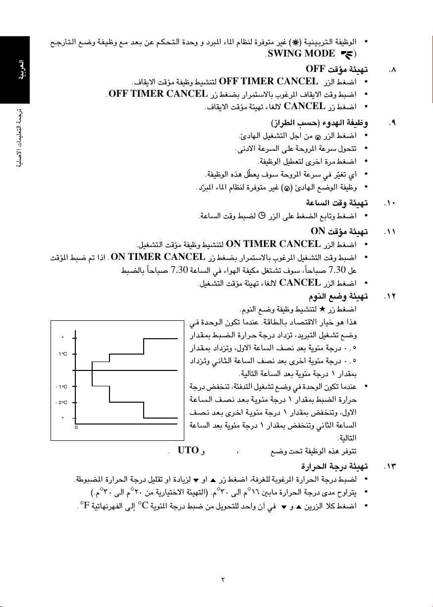
«FdÐOW
WOKô« ULOKF²« WLłdð
XR*« j³{ - «–« Æ
+2 C
+1 C
- 1 C
- 2 C
- 3 C
Æ·UI¹ô« XR WHOþË jOAM²
OFF TIMER CANCEL
Æ
ÆqOGA²« XR WHOþË jOAM²
ON TIMER CANCEL
0 0.5 1 1.5 2
≤∞ s W¹—UO²šô« W¾ON²«® ÆÂ
°
≥∞ v« Â
°
©ÆÂ
WOðUN½dNH« v≈
°F
Æ
°C
® W?O?M?O?Ðd?²?« WHOþu«©`?ł—Q?²?« l?{Ë W?H?O?þË l? b?F?Ð s?Ž r?J?×?²?« …bŠË Ë œd³*« ¡U*« ÂUEM …du² dOž
SWING MODE
Æ
OFF
OFF TIMER CANCEL
—e« jG{«
—“ jGCÐ —«dL²ÝôUÐ »užd*« ·UI¹ô« XË j³{«
Æ·UI¹ô« XR W¾ONð ¡UGô
CANCEL
—“ jG{«
•
(
)
Æ∏ XR W¾ONð
•
•
•
Æπ©“«dD« VŠ® ¡ËbN« WHOþË
OGð Í√
Ò
•
•
•
•
•
—e« jG{«Æ∆œUN« qOGA²« qł« s
Æv½œô« WŽd« vKŽ WŠËd*« WŽdÝ ‰uײð
ÆWHOþu« qODF² Èdš« …d jG{«
DF¹ ·uÝ WŠËd*« WŽdÝ w dÒÆWHOþu« Ác¼ q
Ɯ
Ò
® ∆œUN« l{u« WHOþËd³*« ¡U*« ÂUEM …du² dOž ©
Ʊ∞WŽU« XË W¾ONð
—e« vKŽ jGC« lÐUðË jG{«ÆWŽU« XË j³C
ON
ON TIMER CANCEL
—e« jG{«
—“ jGCÐ —«dL²ÝôUÐ »užd*« qOGA²« XË j³{«
7.30
7.30
UŠU³ Îj³CUÐ
ÆqOGA²« XR W¾ONð ¡UGô
UŠU³ Î WŽU« w ¡«uN« WHOJ qG²Að ·uÝ ¨
CANCEL
—e« jG{«
•
Ʊ± XR W¾ONð
•
•
qŽ
•
Ʊ≤ÂuM« l{Ë W¾ONð
—“ jG{«ÆÂuM« l{Ë WHOþË jOAM²
ÆW?U?D?U?Ð œU?B²ô« —UOš u¼ «c¼w? …b?Šu?« ÊuJð UbMŽ
•
•
—«b?I?0 j?³?C?« …—«d?Š Wł—œ œ«œeð ¨b¹d³²« qOGAð l{Ë
—«b?I?0 œ«œeðË ¨‰Ëô« WŽU« nB½ bFÐ W¹u¾ Wł—œ ∞[µ
œ«œe?ðË w?½U?¦?« WŽU« nB½ bFÐ Èdš« W¹u¾ Wł—œ ∞[µ
ÆWOU²« WŽU« bFÐ W¹u¾ Wł—œ ± —«bI0
Wł—œ iHMð ¨W¾b²« qOGAð l{Ë w …bŠu« ÊuJð UbMŽ
•
W?ŽU??« n?B?½ b?F?Ð W?¹u?¾ Wł—œ ± —«bI0 j³C« …—«dŠ
n?B?½ b?F?Ð Èd?š« W?¹u?¾ Wł—œ ± —«bI0 iHMðË ¨‰Ëô«
WŽU« bFÐ W¹u¾ Wł—œ ± —«bI0 iHMðË w½U¦« WŽU«
ÆWOU²«
AUTO
Æ
HEAT
Ë
COOL
¨
l{Ë X% WHOþu« Ác¼ du²ð
•
Ʊ≥…—«d(« Wł—œ W¾ONð
—“ jG{« ¨WdGK WÐužd*« …—«d(« Wł—œ j³C Ë« ÆWÞu³C*« …—«d(« Wł—œ qOKIð Ë« …œU¹e
≥∞ v« Â
°
±∂ 5ÐU …—«d(« Wł—œ Èb ÕË«d²¹
°
s¹—e« ö jG{« Ë W¹u¾*« Wł—œ j³{ s q¹uײK bŠ«Ë ʬ w
•
•
•
≤
Page 46
qOGA²« qOœ
Æ…bŠuK UNKI½ - b …dOšô« W¾ON²« ÊQÐ bOu² iuð
Æ¡«uN« WHOJ qOGA² …bŠ«Ë …d jG{«
Æ…bŠu« ·UI¹ô Èdš« …d jG{«
wUŽ
–––
wzUIKð
;
ÆWýUA« W{—UŽ vKŽ WŠËd*« WŽdÝ dNEð UbMŽ jGC« sŽ nuð
ÆqOGA²« l{Ë Ÿu½ —UO²šô
∫w¼ …du²*« ŸU{Ëô« Ê« ¨jI b¹d³²« …bŠu
)AUTO (
FAN ( )
Ë
FAN ( )
Æ
¨
Ë
COOL ( )
¨
)DRY (
COOL ( )
¨
)DRY (
¨
Ɯ
Ò
Æ¡«uN« Ê«—Ëœ WHOþË jOAM²
jG{«Ë »užd*« ÁU&ôUÐ oA« „dײ¹ Ê« v« dE²½«Ë
SWING
CK-E
©
·uÝ ¨qI(« j³{ l{Ë ¡UMŁ√ ÆqI(« j³{ l{Ë w ‰ušbK Ê«uŁ ¥ …b*
SWING MODE
Æ
SWING MODE ( )
l?{Ë s
∫w¼Ë ¨WHK²
SWING MODE
;
∫w¼ …du²*« ŸU{Ëô« ¨W¾b²« a{ …bŠu
—“ jG{« ¨5F ÁU&UÐ ¡«uN« l¹“u²
q¹œuLK® `ł—Q²« l{Ë —UO²š« WI¹dÞ
ÆtÐ …—Uýô« qI½ r²¹ Íc« —bB*«
“ON/OFF”
—“ jG{«∫wU²« VOðd²UÐ WŠËd*« WŽdÝ q¹uײ —«dL²ÝUÐ
iHM
–––
jÝu²
–––
;
MODE
—“ jG{«
Æ
wzUIK²« l{u«
d³*« ¡U*« ÂUEM du² dOž
)AUTO (
SWING
—“ jG{«
ÆÈdš« …d —e«
( )
—e« jG{«
ÊUOÐ jI r²¹
SWING ( )
…—«d?(« W?ł—œ —“ jG{« Ë `?ł—Q?²?« l?{Ë d¹Ëbð —UO²šô
Æ≥ `ł—Qð l{Ë v≈ ± `ł—Qð
`ł—Qð ŸU{Ë√ ≥ błu¹
Ʊ‰UÝ—ô« —bB
•
Æ≤…—Uýô« ‰UÝ—« WöŽ
•
Æ≥ —“
•
•
Æ¥WŠËd*« WŽdÝ —UO²š«
•
•
ƵqOGA²« l{Ë
•
•
•
)HEAT (
•
Æ∂¡«uNK wzUIK²« Ê«—Ëb«
•
•
•
•
•
SWING
Æ
`?ł—Q?²?« W?HOþË jOAMð - «–≈ ô≈
MODE ( )
± `ł—Q²« l{Ë≤ `ł—Q²« l{Ë≥ `ł—Q²« l{Ë
SWING MODE
`?ł—Q?ð l?{Ë j?O?AMð r²¹ ô ·uÝ
∫WöFUÐ dýR `ł—Q²«
`?ł—Q?²?« l?{Ë V??Š …bŠu« qG²Að ·uÝ ¨Ê«uŁ ¥ ‰öš l{u« dOOGð ÂbŽ WUŠ w
SWING
Æ—U²<«
jG{«ÆW¾b²« qOGAð Ë« l¹d« b¹d³²K
ÆÈuBI« WŽd« vKŽ WŠËd*« WŽdÝ ‰uײð
ÆWHOþu« qODF² Èdš« …d jG{«
ŸU{Ë« w du²¹
HEAT
Ë
COOL
Ë
DRY
jI
DF¹ ·uÝ WŠËd*« WŽdÝ w dÒÆWHOþu« Ác¼ q
±
OGð Í√
Ò
•
Æ∑©“«dD« VŠ® WOMOÐd²« WHOþu«
•
•
•
•
•
Page 47
iv
Page 48
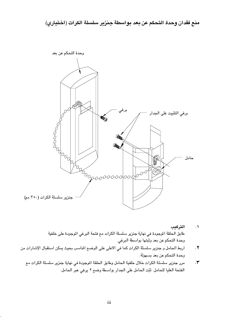
©Í—UO²š«® «dJ« WKKÝ d¹eMł WDÝ«uÐ bFÐ sŽ rJײ« …bŠË Ê«bI lM
bFÐ sŽ rJײ« …bŠË
wždÐ
©3 ≥µ∞® «dJ« WKKÝ d¹eMł
WOHKš vKŽ …œułu*« wžd³« Wײ l «dJ« WKKÝ d¹eMł W¹UN½ w …œułu*« WIK(« oÐUÞ
Æwžd³« WDÝ«uÐ UN²³ŁË bFÐ sŽ rJײ« …bŠË
s «—Uýù« ‰U³I²Ý« sJ1 YO×Ð VÝUM*« l{u« vKŽ vKŽ_« w UL «dJ« WKKÝ d¹eMł Ë qU(« jЗ√
l «dJ« WKKÝ d¹eMł W¹UN½ w …œułu*« WIK(« oÐUÞË qU(« WOHKš ‰öš «dJ« WKKÝ d¹eMł —d
ÆqU(« d³Ž wžd¹ ≤ l{Ë WDÝ«uÐ —«b'« vKŽ qU(« X
—«b'« vKŽ XO³¦²« wždÐ
ÆWuNÐ bFÐ sŽ rJײ« …bŠË
³Ł ÆqU×K UOKF« WײH«
Ò
qUŠ
ƱVOd²«
Æ≤
Æ≥
iii
Page 49
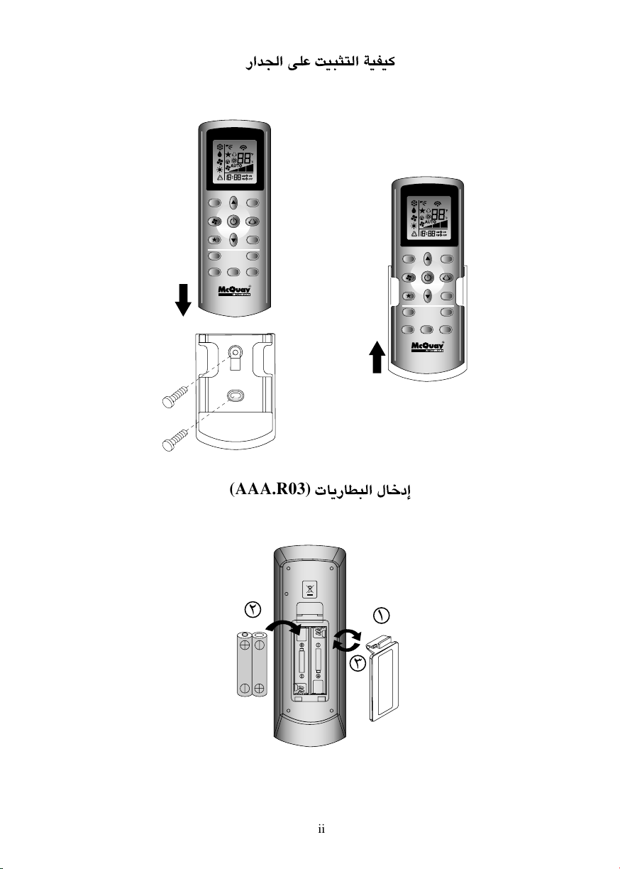
—«b'« vKŽ XO³¦²« WOHO
TURBO QUIET
SLEEP
MODE
TIMER
ON OFF
CLOCK
CANCEL
CANCEL
TURBO QUIET
SLEEP
TIMER
ON OFF
CLOCK
CANCEL
MODE
CANCEL
(AAA.R03)
≤
U¹—UD³« ‰Ušœ≈
±
R03 / AAA 1.5V
R03 / AAA 1.5V
ii
≥
is not in use for a long period of time.
Use 2 "AAA" 1.5V Batteries.
Remove batteries if the air conditioner
Page 50
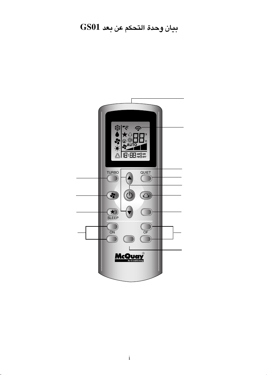
GS01
bFÐ sŽ rJײ« …bŠË ÊUOÐ
1
2
12
11
TURBO QUIET
7
13
9
3
4
SLEEP
ON OFF
CANCEL
TIMER
CLOCK
MODE
CANCEL
6
5
8
10
i
Page 51

Page 52

OM-GS01-1209(0)-McQuay
VOd²« VO²
R08019034087
TURBO QUIET
¡e'« r— ∫
SLEEP
ON OFF
CANCEL
TIMER
CLOCK
MODE
CANCEL
Æq³I²LK lłdL tÐ ÿUH²Šô«Ë W¹UMFÐ «c¼ ULOKF²« VO² …¡«d vłd¹ ¨¡«uN« WHOJ ‰ULF²Ý« q³
 Loading...