

Page 1
Installation and Maintenance Manual
Group: McQuay Controls
Date: July 2002
MicroTech II™
AAF®HermanNelson® Unit Ventilator Controller
LonWorks® Communication Modules
IM 729-0
© 2002 McQuay International
Page 2

Contents
GENERAL INFORMATION ............................................................................................................ 4
DESCRIPTION ..................................................................................................................................... 4
APPLICATION .....................................................................................................................................5
COMPONENT DATA ............................................................................................................................ 5
Service Pin .................................................................................................................................... 6
Light Emitting Diode (LED) ......................................................................................................... 6
LonWorks® Network Connector (TB1)......................................................................................... 6
12-Pin Header............................................................................................................................... 6
Neuron .......................................................................................................................................... 6
Transceiver ................................................................................................................................... 6
Specifications ................................................................................................................................ 6
INSTALLATION................................................................................................................................7
MOUNTING ........................................................................................................................................ 7
To install a MicroTech II™ LonWorks® Communication Module:............................................. 7
To replace a MicroTech II™ LonWorks® Communication Module:........................................... 7
INTEGRATION................................................................................................................................ 10
NETWORK CONNECTION ..................................................................................................................10
Network Topology....................................................................................................................... 10
Free Topology Networks ........................................................................................................................ 10
Free Topology Restrictions..................................................................................................................... 11
Doubly-Terminated Networks ................................................................................................................ 11
Doubly-Terminated Topology Restrictions ............................................................................................ 12
Physical Network ........................................................................................................................12
Qualified Cables ..................................................................................................................................... 12
Network Cable Termination........................................................................................................12
ADDRESSING AND ESTABLISHING COMMUNICATION ....................................................................... 13
LonWorks® Network Addressing................................................................................................ 13
COMMISSIONING THE NETWORK ...................................................................................................... 13
EXTERNAL INTERFACE FILE (XIF)................................................................................................... 13
CONFIGURING THE UNIT CONTROLLER ............................................................................................ 13
SERVICE INFORMATION ............................................................................................................ 14
TEST PROCEDURES........................................................................................................................... 14
REPLACEABLE PARTS LIST .............................................................................................................. 14
Network Connection Plug ........................................................................................................... 14
Generic Replacement Parts ..................................................................................................................... 14
Direct Replacement Parts........................................................................................................................ 14
Kit................................................................................................................................................ 14
Figures
Figure 1. MicroTech II™ LonWorks® communication module.......................................................... 5
Figure 2. MicroTech II™ LonWorks® communication module major components............................ 5
Figure 3. How to mount a LonWorks® communication module on a Unit Controller board .............. 8
Figure 4. Mounting the LonWorks® communication module.............................................................. 8
Figure 5. LonWorks® field wiring ....................................................................................................... 9
Figure 6. Singly-terminated free topology networks .......................................................................... 10
Figure 7. Combining network segments with a repeater..................................................................... 11
Figure 8. Doubly-terminated network topology ................................................................................. 11
2 IM 729-0
Page 3

Limited Warranty
Consult your local McQuay Representative for warranty details. Refer to Form 933-43285Y. To find
your local McQuay Representative, go to www.mcquay.com.
Revision History
IM729-0 8/1/01 Initial release
Reference Documents
Number Source Title
OM748
OM749
OM750
OM751
OM752
OM753
OM754
OM755
OM756
OM757
OM758
ED 15069
ED 15065
IM731
IM747
078-0156-01G
8500_10
078-0120-01E
078-0014-01E
www.McQuay.com
www.McQuay.com
www.McQuay.com
www.McQuay.com
www.McQuay.com
www.McQuay.com
www.McQuay.com
www.McQuay.com
www.McQuay.com
www.McQuay.com
www.McQuay.com
www.McQuay.com
www.McQuay.com
www.McQuay.com
www.McQuay.com
www.lonmark.org
www.lonmark.org
www.lonmark.org
www.lonmark.org
Air Source Heat Pump with Electric Heat (Software Model 00)
Water Source Heat Pump with Electric Heat (Software Model 02)
Water Source Heat Pump without Electric Heat (Software Model 03)
DX Cooling with Electric Heat (Software Model 04)
DX Cooling Only (Software Model 05)
Electric Heat Only (Software Model 06)
DX Cooling with Wet Heat - Valve Control (Software Model 07)
DX Cooling with Wet Heat - F&BP Damper Control (Software Model 08)
2-pipe Wet Heat Only - Valve Control (Software Model 09)
2-pipe Wet Heat Only - F&BP Damper Control (Software Model 10)
2-pipe Heat/Cool - Valve Control (Software Model 11)
2-pipe Heat/Cool - F&BP Damper Control (Software Model 12)
4-pipe Heat/Cool - Valve Control (Software Model 13)
4-pipe Heat/Cool - F&BP Damper Control (Software Model 14)
2-pipe Cooling Only - Valve Control (Software Model 15)
2-pipe Cooling Only - F&BP Damper Control (Software Model 16)
2-pipe Cooling with Electric Heat - Valve Control (Software Model 17)
2-pipe Cooling with Electric Heat - F&BP Damper Control (Software Model 18)
MicroTech II™ Unit Ventilator Unit Controller
Protocol Implementation Conformance Statement
MicroTech II™ AAF®-HermanNelson® Unit Ventilator Unit Controller Protocol Information
MicroTech II™ AAF®HermanNelson® Unit Ventilator Controller BACnet® Communication
Modules
MicroTech II™ Unit Ventilator Unit Controls Installation Manual
LonWorks® FTT-10A Free Topology Transceiver Users Guide
LonMark Functional Profile: Space Comfort Controller, Version 1.0
LonMark Application Layer Interoperability Guidelines, Version 3.2
LonMark Layers 1-6 Interoperability Guidelines, Version 3.0
Notice
Copyright © 2002 McQuay International, Minneapolis MN All rights reserved throughout the world..
™ The following are trademarks or registered trademarks of their respective companies: LonWorks from Echelon Corporation,
Protocol Selectability, MicroTech II, and AAF-HermanNelson from McQuay International.
IM 729-0 3
Page 4
General Information
Use this manual to physically install the communication module onto the Unit Ventilator Unit
Controller board and to make the wiring connections to your network. You also need the appropriate
McQuay Engineering Data Sheet known as the Protocol Information to integrate the unit into your
network. The Protocol Information contains addressing details, LonWorks® protocol information,
and a list of the data points available to the network. See the Reference Documents section of this
document for part numbers of Protocol Information manuals. These documents are available from
your local McQuay International representative and for downloading at the McQuay International
web site: www.mcquay.com.
Electric shock hazard. Can cause personal injury or equipment damage.
This equipment must be properly grounded. Only personnel that are knowledgeable in the
operation of the equipment being controlled must perform connections and service to the
MicroTech II™ control panel.
Static sensitive components. Can cause equipment damage.
Discharge any static electrical charge by touching the bare metal inside the control panel
before performing any service work. Never unplug cables, circuit board terminal blocks, or
power plugs while power is applied to the panel.
! WARNING
!
CAUTION
Description
NOTICE
This equipment generates, uses and can radiate radio frequency energy and, if not installed
and used in accordance with this instruction manual, may cause interference to radio
communication. It has been tested and found to comply with the limits for a Class A digital
device, pursuant to part 15 of the FCC rules. These limits are designed to provide reasonable
protection against harmful interference when the equipment is operated in a commercial
environment. Operation of this equipment in a residential area is likely to cause harmful
interference in which case the user will be required to correct the interference at his or her own
expense. McQuay International disclaims any liability resulting from any interference or
for the correction thereof.
A MicroTech II™ LonWorks® communication module provides the interface between a MicroTech
II™ Unit Controller and a LonWorks® Local Operating Network (LON). It translates the LonTalk
variables used on the network to the variables used in the Unit Controller and vice versa. The
MicroTech II™ LonWorks® board for Unit Ventilators uses the LonMark Space Comfort Control
(SCC) Functional Profile. Profiles are interpreted in loaded programs (firmware).
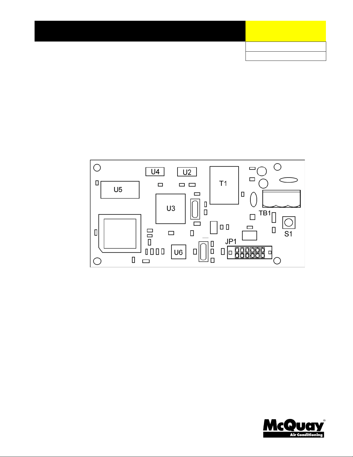
Each MicroTech II™ LonWorks® communication module is a printed circuit board that plugs onto
the MicroTech II™ Unit Controller board. Figure 1 is an outline drawing of that board.
4 IM 729-0
Page 5
Application
Figure 1. MicroTech II™ LonWorks® communication module
A MicroTech II™ LonWorks® communication module connects the MicroTech II™ Unit Controller
to the Building Automation System (BAS) on a LonWorks® network. It is the interface adapter for
the exchange of LonTalk® variables between the network and the Unit Controller. The MicroTech
II™ LonWorks® communication module translates the LonTalk® variables to the Unit Controller.
Refer to the appropriate Unit Operation manual for keypad details. See Reference Documents for
part numbers.
Component Data
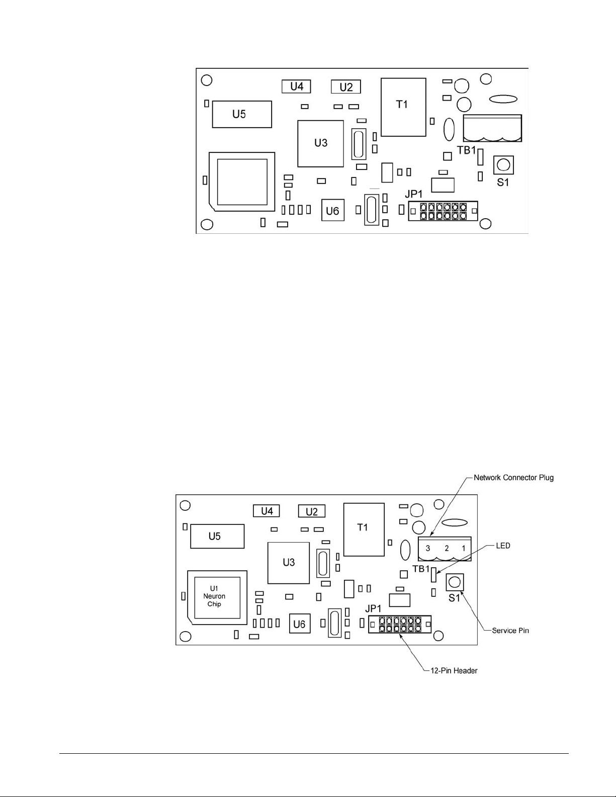
Figure 2 shows the location of the major components of the MicroTech II™ LonWorks®
communication module.
Figure 2. MicroTech II™ LonWorks® communication module major components
IM 729-0 5
Page 6

Service Pin
The service pin switch (S1) generates a service-pin message that contains the Neuron ID. A servicepin message is a network message that is generated by a node and which is broadcast on the network.
It can be used to commission the LonWorks® network.
Light Emitting Diode (LED)
The communication module has an LED that indicates communication to and from the
communication module.
LonWorks® Network Connector (TB1)
TB1 connects the MicroTech II™ LonWorks® communication module to the LonWorks® FTT-10
bus. Since the LonWorks® communication module is polarity insensitive, no polarity must be
observed when making connections via the unshielded twisted-pair wiring.
Pin Designation Function
1 SHLD Not Used
2 -/A FTT-10
3 +/B FTT-10
12-Pin Header
The 12-pin header, JP1, connects the unit-controller Unit Controller board to the LonWorks®
communication module through the bottom of the communication module.
Neuron
The basis of the communication module is an Echelon Neuron chip. Each Neuron chip stores a
globally (i.e., worldwide) unique, 48-bit serial number called the Neuron ID. The Neuron ID can be
used to address the device on the LonWorks® network.
Transceiver
The Echelon Corporation Free Topology Transceiver (FTT-10) is used to communicate on the
LonWorks® network. The network topology may consist of a star, daisy-chain bus, ring, or other
topology (see Figure 6). Data transmission rate on the network is 78-kbps (baud).
Specifications
Characteristic Description
Network Topology Flexible Free Topology
Neuron Chip Processor 3150
Free Topology Transceiver (FTT-10) 50051
Cable Types Belden 8471, NEMA Level 4, or Echelon-approved
equivalent
Maximum Bus Length 1640 ft (500) meters per segment
Maximum Node Separation 1317 ft (400 meters)
Data Transmission Two-wire, half duplex
Data Transmission Rate 78 kbps (baud)
6 IM 729-0
Page 7

Installation
Mounting
The MicroTech II™ LonWorks® communication module can be installed in the field or it can be
installed in the factory. The module mounts on connector pins and is held in place with three plastic,
locking standoffs. Field wiring connections to the LonWorks® network are made at the (supplied)
three-terminal plug (TB1) on the LonWorks® communication module.
To install a MicroTech II™ LonWorks® Communication Module:
1. Disconnect power from the Unit Controller board.
2. Unplug the unwired female network-cable connector from the board-mounted male plug, TB1.
3. Install the three standoffs on the Unit Controller board. (see Figure 3).
4. Locate the 12-pin male connector (JP1) on the Unit Controller board. Orient the printed-circuit
board so that the component side faces out and the connector pins can penetrate the connector
through the bottom of the board. Then push the board onto the connector pins and standoffs until
you hear the faint click of the locking standoffs securing the board in place (see Figure 4).
5. Connect the LonWorks® wiring to the female network-cable connector using a flat-blade
screwdriver. Then reinsert the plug into TB1 on the communication module (see Figure 5).
6. Reapply power to the MicroTech II™ Unit Controller board.
To replace a MicroTech II™ LonWorks® Communication Module:
1. Disconnect power from the Unit Controller board.
2. Unplug the wired female network-cable connector from the board-mounted male plug, TB1.
3. Locate the standoffs for the MicroTech II™ LonWorks® communication module on the Unit
Controller board.
4. Use a pliers or screwdriver to depress the barb on one standoff and gently pull the corner of the
board over the barb. Be careful to not bend the board or misalign the connector pins.
5. Proceed to the other two corners and pull the board over the standoffs.
6. Gently lift the MicroTech II™ LonWorks® communication module from the MCB.
7. Locate the blank connector and four standoffs for the MicroTech II™ LonWorks®
communication module on the Unit Controller board (see Figure 3).
8. Orient the printed-circuit board so that the component side faces out and the connector pins can
penetrate the connector through the board.
9. Push the board onto the connector pins and standoffs until you hear the faint click of the locking
standoffs securing the board in place (see Figure 4)
10. Then reinsert the plug into TB1 on the MicroTech II™ LonWorks® communication module
(see Figure 5).
IM 729-0 7
Page 8

Figure 3. How to mount a LonWorks® communication module on a Unit Controller board
Figure 4. Mounting the LonWorks® communication module
8 IM 729-0
Page 9

Figure 5. LonWorks® field wiring
IM 729-0 9
Page 10

Integration
Ri
Integrating the MicroTech II™ LonWorks® communication module into a BAS involves three steps:
connecting the MicroTech II™ Unit Controller (node) to the network, addressing and establishing
communication with the Unit Controller, and configuring the Unit Controller to the building.
Network Connection
After you have installed the MicroTech II™ Main Control Unit with the MicroTech II™
LonWorks® communication module attached, you must install the MicroTech II™ Unit Controller
into the LonWorks® network.
Network Topology
Each MicroTech II™ LonWorks® communication module is equipped with an FTT-10 transceiver
for network communication. This transceiver allows for (1) free topology network wiring schemes
using twisted pair (unshielded) cable and (2) polarity insensitive connections at each node. These
features greatly simplify installation and reduce network-commissioning problems. Additional nodes
may be added with little regard to existing cable routing.
Free Topology Networks
A LonWorks® “free topology network“ means that devices (nodes) can be connected to the network
in a variety of geometric configurations. For example, devices can be daisy-chained from one device
to the next, connected with stub cables branching off from a main cable, connected using a tree or
star topology, or any of these configurations can be mixed on the same network.
6. Free topology segments require termination for proper transmission performance. Only one
termination is required. It may be placed anywhere along the segment. Refer to Echelon
LonWorks® FTT-10 Transceiver User’s Guide. See Reference Documents for part number.
Free topology networks may take on the following topologies:
• Bus
• Ring
• Star
• Mixed - Any combination of Bus, Ring, and Star
As shown in Figure
Note: Limitations to wire lengths apply and must be observed.
Figure 6. Singly-terminated free topology networks
ng Topology
Singly Terminated Bus Topology
Termination
Termination
10 IM 729-0
Termination
Mixed Topology
Stub
}
Star Topology
Termination
Page 11

A network segment is any part of the free topology network in which each conductor is electrically
continuous. Each of the four diagrams in is an illustration of a network segment. Some applications
may require two or more segments; see “Free Topology Restrictions.” If necessary, segments can be
joined with FTT-10-to-FTT-10 physical layer repeaters. See Figure 7. Refer to Echelon
LonWorks® FTT-10 Transceiver User’s Guide. See Reference Documents for part number.
Figure 7. Combining network segments with a repeater
Termination Termination
FTT-10A
FTT-10A
Free Topology Restrictions
Although free topology wiring is very flexible, there are restrictions. A summary follows, refer to the
Echelon FTT-10 User’s Guide for details. See Reference Documents for part number.
1. The maximum number of nodes per segment is 64.
2. The maximum total bus length depends on the wire size (see “Qualified Cables” for details):
Wire Size Maximum Node-to-Node Length Maximum Cable Length
24 AWG 820 ft (250 m) 1476 ft (450 m)
22 AWG 1312 ft (400 m) 1640 ft (500 m)
16 AWG 1640 ft (500 m) 1640 ft (500 m)
The longest cable path between any possible pair of nodes on a segment must not exceed the
maximum node-to-node distance. If two or more paths exist between a pair of nodes (e.g., a loop
topology), the longest path should be considered. Note that in a bus topology, the longest nodeto-node distance is equal to the total cable length.
a. The total length of all cable in a segment must not exceed the maximum total cable length.
3. One termination is required in each segment. It may be located anywhere along the segment.
Doubly-Terminated Networks
You can extend the maximum total cable length without using a repeater by using doubly-terminated
network topology. See Figure 8 The trade-offs are (1) this network topology must be rigorously
followed during the installation and subsequent retrofits and (2) two terminations must be installed at
the ends of the bus for proper transmission performance. Refer to Echelon LonWorks® FTT-10
Transceiver User’s Guide. See Reference Documents for part number.
Note: Limitations to wire lengths apply and must be observed.
Figure 8. Doubly-terminated network topology
Termination Termination
IM 729-0 11
Page 12

Doubly-Terminated Topology Restrictions
The restrictions on doubly-terminated bus topology are as follows:
1. The maximum number of nodes per segment is 64.
2. The maximum total bus length depends on the wire size (see “Qualified Cables” for details):
Wire Size Maximum Cable Length
24 AWG 2952 ft (900 m)
22 AWG 4590 ft (1400 m)
16 AWG 8855 ft (2700 m)
3. The maximum stub length is 9.8 ft (3 m). The length of the cable harness stub is 7.2 ft (2.19 m).
A stub is a piece of cable that is wired between the node and the bus. See Figure 6. Note that if
the bus is wired directly to the node, there is no stub, and thus the stub length is zero. If you are
wiring to a field terminal strip on a unit, be sure to account for any factory wiring between the
terminal strip and the controller. This wiring is considered part of the stub.
4. Two terminations are required in each segment. One must be located at each end of the bus.
Physical Network
Qualified Cables
Echelon has qualified three twisted-pair network communication cables that are available from a
large number of different sources. Refer to Echelon LonWorks® FTT-10 Free Topology
Transceiver Users Guide. See Reference Documents for part number. Some local codes or
applications may require the use of plenum rated cable. The following cables meet this specification.
1. Belden 8471, NEMA Level 4, or Echelon-approved equivalent.
Do not install the cable in the same conduit with power wiring. The temperature of the cable must
not exceed 131°F (55°C).
Note: Ideally, you should connect two controllers with one continuous piece of cable in order to
reduce the risk of communication errors. If you must splice the cable, use crimp-type butt
connectors (good) or solder (best). Do not use wire nuts.
Network Cable Termination
LonWorks® network segments require termination for proper data transmission performance. The
type and number of terminations depend on network topology. Refer to Echelon LonWorks® FTT-
10 Transceiver User’s Guide. See Reference Documents for part number.
12 IM 729-0
Page 13

Addressing and Establishing Communication
LonWorks® Network Addressing
Every Neuron Chip has a unique 48-bit Neuron ID or physical address. This address is generally
used only at initial installation or for diagnostic purposes. For normal network operation, a device
address is used.
Device addresses are defined at the time of network configuration. All device addresses have three
parts. The first part is the Domain ID, designating the domain. Devices must be in the same domain
in order to communicate with each other. The second part is the Subnet ID that specifies a collection
of up to 127 devices that are on a single channel or a set of channels connected by repeaters. There
may be up to 255 subnets in a domain. The third part is the Node ID that identifies an individual
device within the subnet.
A group is a logical collection of devices within a domain. Groups are assembled with regard for
their physical location in the domain. There may be up to 256 groups in a domain. A group address is
the address that identifies all devices of the group. There may be any number of devices in a group
when unacknowledged messaging is used. Groups are limited to 64 devices if acknowledged
messaging is used.
A broadcast address identifies all devices within a subnet or domain.
Commissioning the Network
Pressing the service pin, switch S1, generates a service pin message, which contains the Neuron ID
and the program code identification of the node. A service pin message is a network message that is
generated by a node and broadcast on the network. It can be used to commission the LonWorks®
network.
A network configuration tool maps device Neuron IDs to the domain/subnet/node logical addressing
scheme when it creates the network image, the logical network addresses and connection information
for all devices (nodes) on the network.
External Interface File (XIF)
LonMark guidelines specify exact documentation rules so that proprietary configuration tools are not
required to commission and configure LonWorks® devices. The MicroTech II™ LonWorks®
communication module is self-documenting so that any network management tool can obtain all the
information needed over the network to connect it into the system and to configure and manage it.
An external interface file (a specially formatted PC text file with an extension .XIF) is also available
so that any network tool can design and configure it prior to installation. For a copy of the XIF file
you can contact your local McQuay International representative or locate it on www.mcquay.com
under Product Interoperability, Unit Ventilators, Control Integration.
Configuring the Unit Controller
The MicroTech II™ Unit Ventilator Controller LonWorks® communication module is configured at
the factory as a unit ventilator in accordance with the LonMark Space Comfort Control (SCC)
functional profile. The unit is ready to operate with the default values of the various parameters set at
the factory. Default values may be changed with the unit’s keypad or via the network. See the
appropriate operation manual for default values and keypad operation instruction and see the
MicroTech II™ Unit Ventilator Protocol Information Data for descriptions of the network variables.
See Reference Documents for part numbers.
IM 729-0 13
Page 14

Service Information
Test Procedures
If you can control the unit from the unit’s keypad, but you are unable to communicate with the unit
via the network:
• Check the network wiring
• Check the cable harness to the network terminals
• Check addressing -- press the Service Pin on the communication module to send the service
message to the network. The service pin message contains the Neuron ID and the program code
identification of the node.
If the MicroTech II™ Unit Ventilator LonWorks® communication module still doesn’t respond,
replace the communication module.
Replaceable Parts List
Network Connection Plug
Generic Replacement Parts
The three-contact network connector plug has custom markings, but if you lose this terminal block
you can replace it with a standard block without the markings from a manufacturer. The list below
contains manufacturers part numbers for equivalent parts without the custom markings.
Manufacturer Telephone Order Number
Phoenix Contact (800) 888-7388 17 57 02 2
Altech Corp (908) 806-9400 37.003
Direct Replacement Parts
You can order direct replacement parts for these connector plugs from McQuay International (1-80037-PARTS).
Part Number Description
AP-TBN3COM-0 10 terminal blocks marked LON A, LON B, and SHIELD
AS-TBKIT-0 5 terminal blocks marked REF, N2- and N2+ and
5 terminal blocks marked 24VAC, COM and ZBUS
Kit
Component Description Part No.
Kit LonMark communication module for unit ventilators with
standoffs
107293127
13600 Industrial Park Boulevard, Minneapolis, MN 55440 USA (763) 553-5330 (www.mcquay.com)
 Loading...