

Page 1
®
Installation & Maintenance Data
McQuay® Enfinity™ (R-410A) and Standard (R-22)
Horizontal Water Source Heat Pumps
Model CRH, CRW Unit Sizes 007 – 070 / R-22 Refrigerant
Model CCH, CCW Unit Sizes 007 – 060 / R-410A Refrigerant
IM 742-4
Group: WSHP
Part Number: 106586605
Date: September 2007
Model Nomenclature . . . . . . . . . . . . . . . . . . . . . . . . . . . 2
Transportation & Storage
Installation . . . . . . . . . . . . . . . . . . . . . . . . . . . . . . . . . .2-4
Electrical Data . . . . . . . . . . . . . . . . . . . . . . . . . . . . . . . . 5
Piping . . . . . . . . . . . . . . . . . . . . . . . . . . . . . . . . . . . . . . . 5
Cleaning & Flushing System . . . . . . . . . . . . . . . . . . . . .
Start-up. . . . . . . . . . . . . . . . . . . . . . . . . . . . . . . . . . . . . . 7
Operating Limits . . . . . . . . . . . . . . . . . . . . . . . . . . . . . . . 8
Typical Wiring Diagrams. . . . . . . . . . . . . . . . . . . . . . .9-11
©2007 McQuay International
. . . . . . . . . . . . . . . . . . . . . . . . 2
Contents
Unit Operation . . . . . . . . . . . . . . . . . . . . . . . . . . . . .12-14
Thermostat Connections . . . . . . . . . . . . . . . . . . . . .16-17
Options for Mark IV/AC Units. . . . . . . . . . . . . . . . . .18-21
Field Installed Options on MicroTech Units . . . . . . . . . 22
Sequence of Operation . . . . . . . . . . . . . . . . . . . . . . . . 23
6
Troubleshooting WSHP . . . . . . . . . . . . . . . . . . . . . .24-25
Troubleshooting Refrigeration Circuit. . . . . . . . . . . . . . 25
Typical Refrigeration Cycles. . . . . . . . . . . . . . . . . . . . . 26
General Maintenance . . . . . . . . . . . . . . . . . . . . . . . . . . 27
Page 2
Model Nomenclature
Note: For illustration purposes only. Not all options available with all models.
Please consult McQuay Sales Representative for specific availability.
W CCH 1 009 M E Y L S
Product Catagory
W = WSHP
Product Identifier
CCH = Ceiling Mounted / R-410A / Standard Range
CCW = Ceiling Mounted / R-410A / Geothermal
CRH = Ceiling Mounted / R-22 / Standard
CRW = Ceiling Mounted / R-22 / Geothermal
Design Series
1 = A Design
2 = B Design
3 = C Design
4 = D Design
Nominal Capacity
007 = 7,000 030 = 30,000
009 = 9,000 036 = 36,000
012 = 12,000 042 = 42,000
015 = 15,000 048 = 48,000
019 = 19,000 060 = 60,000
024 = 24,000 070 = 70,000
Controls
M = Mark IV
K = Micortech 2000 w/LonMark® 3.3
L = Microtech 2000 w/LonTaLk
A = BACnet
E = Less Board
®
Note: Installation and maintenance are to be performed only by qualified personnel who are familiar with local codes and regulations, and are
experienced with this type of equipment. Caution: Sharp edges are a potential injury hazard. Avoid contact with them.
Discharge Air
S = Straight
E = End
Return Air
L = Left
R = Right
Future
(None)
Voltage
A = 115/60/1
E = 208-230/60/1
F = 208-230/60-/3
J = 277-265/60/1
K = 460/60/3
L = 575/60/3
50 Hz (CCH&CCW Only)
M = 230/50/1
N = 380/50/3
Transportation & Storage
Upon receipt of the equipment, check carton for visible
damage. Make a notation on the shipper’s delivery ticket
before signing. If there is any evidence of rough handling,
immediately open the cartons to check for concealed damage. If any damage is found, notify the carrier within 48
hours to establish your claim and request their inspection
and a report. The Warranty Claims Department should then
be contacted.
Do not stand or transport the machines on end. For stor
ing, each carton is marked with “up” arrows.
Installation
General
1. To prevent damage, this equipment should not be operated for supplementary heating and cooling during the
construction period.
-2. Inspect the carton for any specific tagging numbers
indicated by the factory per a request from the installing
contractor. At this time the voltage, phase and capacity
should be checked against the plans.
3. Check the unit size against the plans to ensure unit
installation is in the correct location.
4. After removing the carton, remove the hanger kit from
the fan housing.
5. Before installation, check the available ceiling height
versus the height of the unit.
6. Note the location and routing of water piping, conden
sate drain piping, and electrical wiring. The locations of
these items are clearly marked on submittal drawings.
7. The installing contractor will find it beneficial to confer
with piping, sheet metal, ceiling and electrical foremen
before installing any conditioners.
In the event that elevator transfer makes up-ended positioning unavoidable, absolutely ensure that the machine is
in the normal upright position for at least 24 hours before
operating.
Temporary storage at the job site must be indoors,
completely sheltered from rain, snow, etc. High or low tem
peratures naturally associated with weather patterns will
not harm the conditioners. Excessively high temperatures,
140°F (60°C) and higher, may deteriorate certain plastic
materials and cause permanent damage.
NOTE: Check the unit name plate for correct voltage with
the plans before installing the equipment. Also,
make sure all electrical ground connections are
made in accordance with local code.
8. Remove all shipping blocks in the fan wheel.
9. Change the airflow direction from straight discharge to
end discharge or vice versa before the unit is installed
in the ceiling. Refer to the section in this bulletin for
instructions.
10. We recommend that the contractor cover the condi
tioners with plastic film to protect the machines during
finishing of the building. This is critical while spraying
fireproofing material on bar joists, sandblasting, spray
painting and plastering. If plastic film is not available,
-
the shipping carton may be modified to cover the units
during construction.
-
-
Page 2 / IM 742
Page 3
Unit Location
B
Coil
Airflow
E
C
D
Comp
Control
Box
Fan
Assembly
A
1. Locate the unit in an area that allows for easy removal
of the filter and access panels. Leave a minimum of 18”
of clearance around the heat pump for easy removal,
and to perform routine maintenance, or troubleshooting.
Provide sufficient room to make water, electrical and duct
connections.
2. The contractor should make sure that adequate ceil
ing panel access exists, including clearance for hanger
brackets, duct collars and fittings at water and electrical
connections.
3. Allow adequate room below the unit for a condensate
trap and do not locate the unit above pipes.
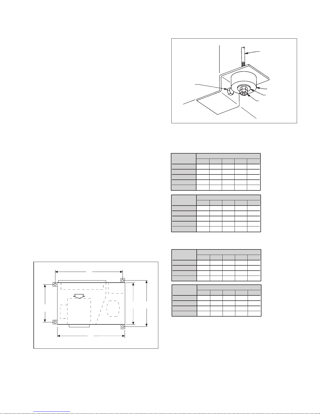
4. Each unit is suspended from the ceiling by four threaded
rods. The rods are attached to the unit corners by a hanger
bracket through a rubber isolator.
Caution: Do not use
rods smaller than shown in Figure 1B. The rods must
be securely anchored to the ceiling or to the bar
joists.
5. Each unit is furnished with a hanger kit. The kit is shipped
unassembled and includes hanger brackets, rubber
isolators, washers, bolts and lock washers. Lay out the
threaded rods per the dimension in Figures 1A and 1B.
6. When attaching the hanger rods to the unit, a double nut
is recommended since vibration could loosen a single
nut. The installer is responsible for providing the hex nuts
when installing hanger rods.
7. Leave minimum 3" (76 mm) extra threaded rod below the
double nuts or minimum 3" (76 mm) clearance between
top of unit and ceiling above to facilitate top panel removal for servicing.
Filter Access
Each unit is shipped with a filter bracket for side filter removal. For bottom removal push the filter up into top bracket to
gain clearance of bottom bracket and remove the filter. Also,
a sheet metal duct filter retainer can be fabricated when
return air duct work is used.
Figure 1A. Hanger bracket detail, sizes 007 thru 070
Figure 1B. Unit sizes 007 thru 070
-
Bolt & Lock
Washer
Hanger Bracket Dimensions
Models CCH & CCW
UNIT DIMENSIONS (INCHES)
SIZE A B C D E
007 – 009 17.5 34 22 34 20
012 17.5 40 22 40 20
019 – 024 17.5 40 22 40 20
030 – 036 18.5 46 23 46 21
042 – 060 25.5 52 30 52 28
UNIT DIMENSIONS (mm)
SIZE A B C D E
007 – 009 445 864 559 864 508
012 445 1016 559 1016 508
019 – 024 445 1016 559 1016 508
030 – 036 470 1168 584 1168 533
042 – 060 648 1321 762 1321 711
Models CRH & CRW
UNIT DIMENSIONS (INCHES)
SIZE A B C D E
007 – 012 17.5 34 22 34 20
015 – 024 17.5 42 22 42 20
030 – 042 18.5 46 23 46 21
048 – 070 25.5 52 30 52 28
3/8" Threaded Rod
(By Others)
Vibration Isolator
Washer
Hex Nuts
(By Others)
UNIT DIMENSIONS (mm)
SIZE A B C D E
007 – 012 445 864 559 864 508
015 – 024 445 1067 559 1067 508
030 – 042 470 1168 584 1168 533
048 – 070 648 1321 762 1321 711
IM 742 / Page 3
Page 4

Air Discharge Conversion
Unit sizes 007 thru 070 can be shipped as straight discharge
air or end discharge air arrangement. In the event that the
unit needs to be converted from straight discharge to end
discharge:
1. Remove top panel.
2. Remove the access panel to the fan motor. Remove the
piece of insulation at the bottom on the side of the bottom
panel.
3. Remove the fan discharge panel, rotate it 180 degrees,
and move it to the other side. In other words, with straight
Ductwork & Attenuation
Discharge ductwork is normally used with these conditioners. Return air ductwork may also be required.
All ductwork should conform to industry standards
of good practice as described in the ASHRAE Systems
Guide.
The discharge duct system will normally consist of a
flexible connector at the unit, a transition piece to the full
duct size, a short run of duct, an elbow without vanes, and
a trunk duct teeing into a branch duct with discharge diffusers as shown in Figure 2. The transition piece must not
have angles totaling more than 30° or severe loss of air
performance can result. Do not connect the full duct size to
the unit without using a transition piece down to the size of
the discharge collar on the unit. With metal duct material,
the sides only of the elbow and entire branch duct should
be internally lined with acoustic fibrous insulation for sound
attenuation. Glass fiber duct board material is more absorb
ing and may permit omission of the canvas connector.
The ductwork should be laid out so that there is no line of
sight between the conditioner discharge and the distribution
diffusers.
air discharge the housing is bottom horizontal and with
an end discharge the housing is top horizontal.
4. Remove the three bolts holding the fan motor on and
rotate it so that the motor oilers are in the up position.
5. Install insulation base panel below new access panel
location.
6. Reinstall the top panel.
7. Reinstall the piece of insulation and the access panel.
Return air ducts can be brought in through a low side
wall filter-grille and then up through the stud pieces to
a ceiling plenum or through air ceiling filter-grilles. The
ceiling filter-grille must not be placed directly under the
conditioner.
Return air ductwork can be connected to the standard
filter rack. See Figure 3 (side filter removal shown). The filter
rack can be installed for bottom filter removal or side filter
removal by locating the brackets. For side filter removal the
brackets should be located on the bottom, left side, and top.
For bottom filter removal the brackets should be mounted on
the left side top and right side with the spring clips supporting the filter.
Do not use sheet metal screws directly into the unit cabi
net for connection of supply or return air ductwork, especially return air ductwork which can hit the drain pan or the
air coil.
-
-
Figure 2. Suggested duct layout
Both Sides Internally Lined With
Acoustic Fibrous Glass Insulation
Transformation
Piece
Discharge Collar
On Heat Pump
Suggested Duct Layout For
Multiple Diffuser Application
Heat
Pump
Canvas
Collar
Square Elbow
2x2 Ft.
Diffuser
(Example
Only)
Trunk Duct
Branch Duct
Internally Lined
With Acoustic
Fibrous
Insulation
Ventilation Air
Ventilation may require outside air. The temperature of the
ventilation air must be controlled so that mixture of outside
air and return air entering the conditioner does not exceed
conditioner application limits. It is also typical to close off
the ventilation air system during unoccupied periods (night
setback).
Figure 3. Filter rack/return air duct collar
Standard 1" (25mm)
Optional 2" (51 mm) Rack also
available.
The ventilation air system is generally a separate building
subsystem with distribution ductwork. Simple introduction of
the outside air into each return air plenum chamber reasonably close to the conditioner air inlet is recommended. Do
not duct outside air directly to the conditioner inlet. Provide
sufficient distance for thorough mixing of outside and return
air. See Operating Limits on page 8.
Page 4 / IM 742
Page 5

Electrical Data
1. Verify the compatibility between the voltage and phase
of the available power and that shown on the unit serial
plate. Line and low voltage wiring must comply with
local codes or the National Electrical Code, whichever
applies.
7
2. Apply correct line voltage to the unit. A
and/or a 11⁄8" (29 mm) knockout is supplied on the side
of the unit. A disconnect switch near the unit is required
by code. Power to the unit must be sized correctly and
have dual element (Class RK5) fuses or an HACR circuit
All 208-230 volt single-phase and three-phase units are
factory wired for 208 volt operation. For 230 phase opera
tion, the line voltage tap on the 24 volt transformer must be
All fan motors are multi-speed, PSC type with integral
mounting brackets and thermal overload protection. The
motor is isolated from the fan housing for minimum vibration
transmission. Fan motors on 019 thru 070 have a terminal
strip on the motor body for simple motor speed change
without going back to the control box. To change fan motor
speed to high on size 015 through 048, interchange the red
wire with the black wire. For low speed, sizes 012, 024,
030, 036, 042, 060 and 070, interchange the black wire with
the red wire. To change the 460 volt motor from high to low
Figure 4. CCH, CCW, CRH & CRW Sizes 007 thru 070
(Factory wired)
⁄8" (22mm) hole
General
230 Volt Operation
Fan Assembly
breaker for branch circuit overcurrent protection. See the
nameplate for correct ratings.
3. Three phase 50 cycle units, 380/50/3, require a neutral
wire for 230/50/1 power to the fan circuit.
4. Connect the thermostat/subbase wiring with the power
“off ” to the unit.
Field supplied relays installed on the input terminals W1, W2, Y1,
5.
Y2 or G may introduce electrical noise. Never install relay coils in
series with the inputs.
changed. Disconnect and cap the red lead wire and interchange it with the orange lead wire on the primary of the 24
volt transformer.
speed, interchange Black and Red wires, then add jumper
between Black and Blue wires. All the fan/motor assemblies
have a removable orifice ring on the housing to accommodate motor and fan wheel removal without disconnecting the
ductwork. The fan housing protrudes through the cabinet
allowing adequate material for connection of flexible duct.
Each model unit is shipped from the factory for maximum
performance and minimum sound requirements. Fan sound
levels and performance can be affected by external static
pressure.
Figure 4a. CCH, CCW, CRH & CRW Sizes 042 thru 070
(Factory wired, 460 volt motor only)
1. All units should be connected to supply and return piping in a two-pipe reverse return configuration. A reverse
return system is inherently self-balancing and requires
only trim balancing where multiple quantities of units
with different flow and pressure drop characteristics
exist in the same loop. Check for proper water balance
by measuring differential temperature reading across
the water connections. To insure proper water flow, the
differential flow should be 10°F to 14°F (5°C to 8°C) for
units in cooling mode.
A direct return system may also work acceptably, but
proper water flow balancing is more difficult to achieve
and maintain.
2. The piping can be steel, copper or PVC.
3. Supply and return runouts usually join the unit via short
lengths of high pressure flexible hose which are sound
attenuators for both unit operating noise and hydraulic
pumping noise. One end of the hose should have a
swivel fitting to facilitate removal for service. Hard pip
Note: For low speed applications a jumper must be installed between the motor's Black and
Blue terminal.
Piping
4. Some flexible hose threaded fittings are supplied with
5. Supply and return shutoff valves are required at each
6. No unit should be connected to the supply and return
-
ing can also be brought directly to the unit. This option
is not recommended since no vibration or noise attenuation can be accomplished. The hard piping must have
unions to facilitate unit removal. See Figure 5 for typical
piping setup.
sealant compound. If not, apply Teflon tape to assure a
tight seal.
conditioner. The return valve is used for balancing and
should have a “memory stop” so that it can always be
closed off but can only be reopened to the proper position for the flow required.
piping until the water system has been cleaned and
flushed completely. After the cleaning and flushing
has taken place, the initial connection should have
all valves wide open in preparation for water system
flushing.
IM 742 / Page 5
Page 6
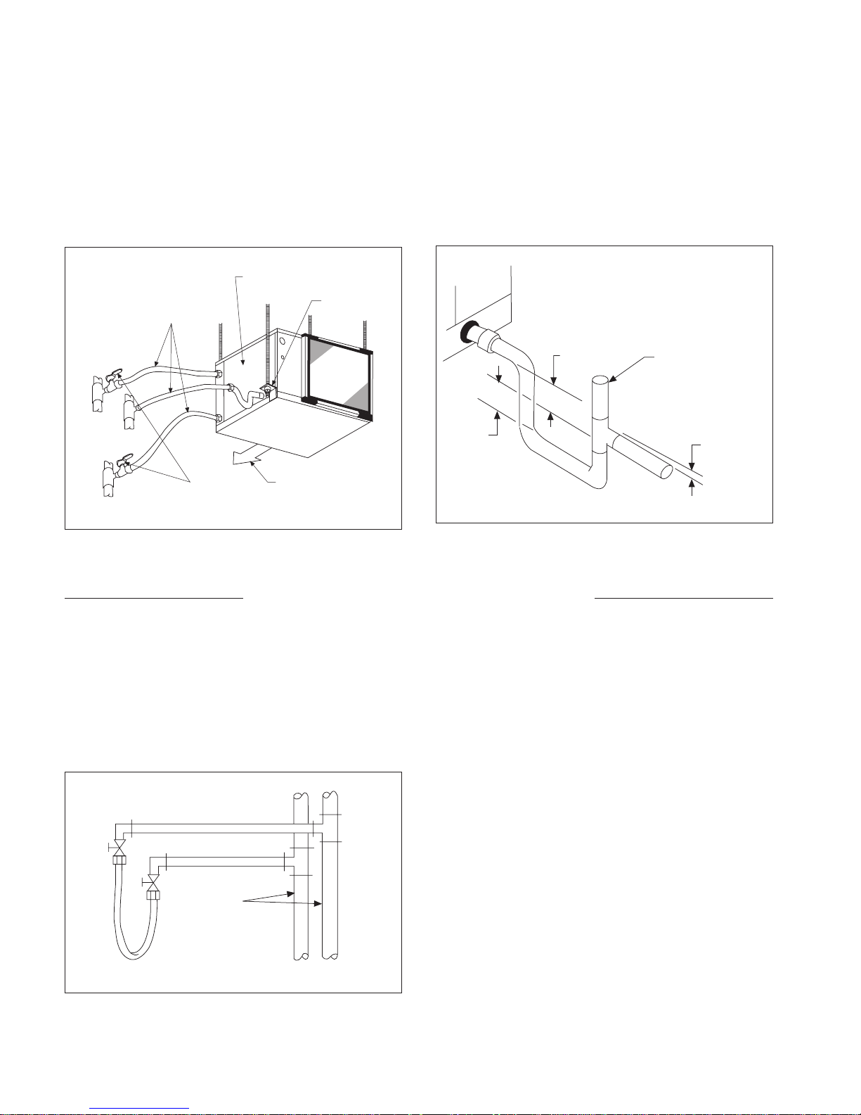
7. Condensate piping can be steel, copper or PVC. Each
unit includes a condensate connection.
8. The condensate disposal piping must be trapped. The
piping must be pitched away from the unit not less than
1
⁄4" per foot. The unit has a 3/4 inch female pipe fitting
on each water source heat pump to accommodate the
condense drain connection. Factory supplied conden
sate hose assemblies have a pipe thread fitting to facilitate connection of a flexible vinyl or steel braided hose.
A complete copper or PVC condense system can be
used. Union fittings in the copper or PVC lines should
be applied to facilitate removal.
9. Do not locate any point in the drain system above the
drain connection of any unit.
10. Automatic flow controlled devices must not be installed
-
prior to system cleaning and flushing.
11. A high point of the piping system must be vented.
12. Check local code for the need for dielectric fittings.
Figure 5. (Sizes 007 through 070 shown)
Electrical Access Panel
Hanger Kits (4)
Flex Hoses
Return
Riser
Condensate
Riser
Ball
Supply
Riser
Note: Do not overtorque fittings. The maximum torque without damage to fittings is 30 foot pounds. If a torque wrench is not available, use as a rule of thumb,
finger-tight plus one quarter turn.
Valves
Supply Air
Figure 6. Condensate disposal trapping detail
11⁄2"
11⁄2"
(38 mm)
(38 mm)
Optional Field
Installed Vent
1
⁄4" Per Foot
(21 mm Per
Meter)
Cleaning & Flushing System
1. Prior to first operation of any conditioner, the water
circulating system must be cleaned and flushed of all
construction dirt and debris.
If the conditioners are equipped with water shutoff
valves, either electric or pressure operated, the supply
and return runouts must be connected together at each
conditioner location. This will prevent the introduction of
dirt into the unit. See Figure 7.
Figure 7. Supply & return runouts connected together
Return Runout
Supply Runout
Mains
Flexible Hose
Runouts Initially
Connected Together
2. Fill the system at the city water makeup connection with
all air vents open. After filling, close all air vents.
The contractor should start main circulator with the
pressure reducing valve open. Check vents in sequence
to bleed off any trapped air, ensuring circulation through
all components of the system.
Power to the heat rejector unit should be off, and the
supplementary heat control set at 80°F (27°C).
While circulating water, the contractor should check
and repair any leaks in the piping. Drains at the lowest
point(s) in the system should be opened for initial flush
and blowdown, making sure city water fill valves are set
to make up water at the same rate. Check the pressure
gauge at pump suction and manually adjust the makeup
to hold the same positive steady pressure both before
and after opening the drain valves. Flush should continue
for at least two hours, or longer if required, to see clear,
clean drain water.
3. Shut off supplemental heater and circulator pump and
open all drains and vents to completely drain down the
system. Short circuited supply and return runouts should
now be connected to the conditioner supply and return
connections. Do not use sealers at the swivel flare con
nections of hoses.
4. Trisodium phosphate was formerly recommended as a
cleaning agent during flushing. However, many states
and localities ban the introduction of phosphates into
their sewage systems. The current recommendation is to
simply flush longer with warm 80°F (27°C) water.
-
Page 6 / IM 742
Page 7

5. Refill the system with clean water. Test the water using
litmus paper for acidity, and treat as required to leave the
water slightly alkaline (pH 7.5 to 8.5). The specified per
centage of antifreeze may also be added at this time. Use
commercial grade antifreeze designed for HVAC systems
only. Do not use automotive grade antifreeze.
Once the system has been filled with clean water
and antifreeze (if used), precautions should be taken
to protect the system from dirty water conditions. Dirty
water will result in system wide degradation of performance and solids may clog valves, strainers, flow regulators, etc. Additionally, the heat exchanger may become
clogged which reduces compressor service life or causes
premature failure.
Start-up
1. Open all valves to full open position and turn on power
to the conditioner.-
2. Set thermostat for “Fan Only” operation by selecting
“Off” at the system switch and “On” at the fan switch. If
“Auto” fan operation is selected, the fan will cycle with
the compressor. Check for proper air delivery.
3. For those units that have two-speed motors, reconnect
for low speed operation if necessary.
4. Set thermostat to “Cool.” If the thermostat is an automat
ic changeover type, simply set the cooling temperature
to the coolest position. On manual changeover types
additionally select “Cool” at the system switch.
Again, many conditioners have time delays which
protect the compressor(s) against short cycling. After
a few minutes of operation, check the discharge grilles
for cool air delivery. Measure the temperature differ
ence between entering and leaving water. It should be
approximately 11⁄2 times greater than the heating mode
temperature difference. For example, if the cooling
temperature difference is 15°F (8°C), the heating temperature difference should have been 10°F (5°C).
Without automatic flow control valves, target a cooling
temperature difference of 10°F to 14°F (5°C to 8°C).
Adjust the combination shutoff/balancing valve in the
return line to a water flow rate which will result in the
10˚F to 14°F (5°C to 8°C) difference.
5. Set thermostat to “Heat.” If the thermostat is the auto
matic changeover type, set system switch to the “Auto”
position and depress the heat setting to the warmest
selection. Some conditioners have built-in time delays
which prevent the compressor from immediately starting. With most control schemes, the fan will start imme
diately. After a few minutes of compressor operation,
check for warm air delivery at discharge grille. If this is
6. Set the loop water controller heat add setpoint to 70°F
-
-
-
-
-
(21°C) and the heat rejection setpoint to 85°F (29°C).
Supply power to all motors and start the circulating
pumps. After full flow has been established through all
components including the heat rejector (regardless of
season) and air vented and loop temperatures stabilized,
each of the conditioners will be ready for check, test and
start-up, air balancing, and water balancing.
a “cold building” start-up, leave unit running until return
air to the unit is at least 65°F (18°C).
Measure the temperature difference between enter
ing and leaving air and entering and leaving water. With
entering water of 60°F to 80°F (16°C to 27°C), leaving
water should be 6°F to 12°F (3.3°C to 6.6°C) cooler,
and the air temperature rise through the machine
should not exceed 35°F (19°C). If the air tempera
ture exceeds 35°F (19°C), then the water flow rate is
inadequate.
6. Check the elevation and cleanliness of the condensate
line. If the air is too dry for sufficient dehumidification,
slowly pour enough water into the condensate pan to
ensure proper drainage.
7. If the conditioner does not operate, check the following
points:
a. Is supply voltage to the machine compatible?
b. Is thermostat type appropriate?
c. Is thermostat wiring correct?
8. If the conditioner operates but stops after a brief period:
a. Is there proper airflow? Check for dirty filter, incor
rect fan rotation (3-phase fan motors only), or incorrect ductwork.
b. Is there proper water flow rate within temperature
limits? Check water balancing; backflush unit if dirtclogged.
9. Check for vibrating refrigerant piping, fan wheels, etc.
10. Do not lubricate the fan motor during the first year of
operation as it is prelubricated at the factory.
Field supplied relays installed on the input terminals W1, W2,
11.
Y1, Y2 or G may introduce electrical noise. Never install relay
coils in series with the inputs.
-
-
-
IM 742 / Page 7
Page 8
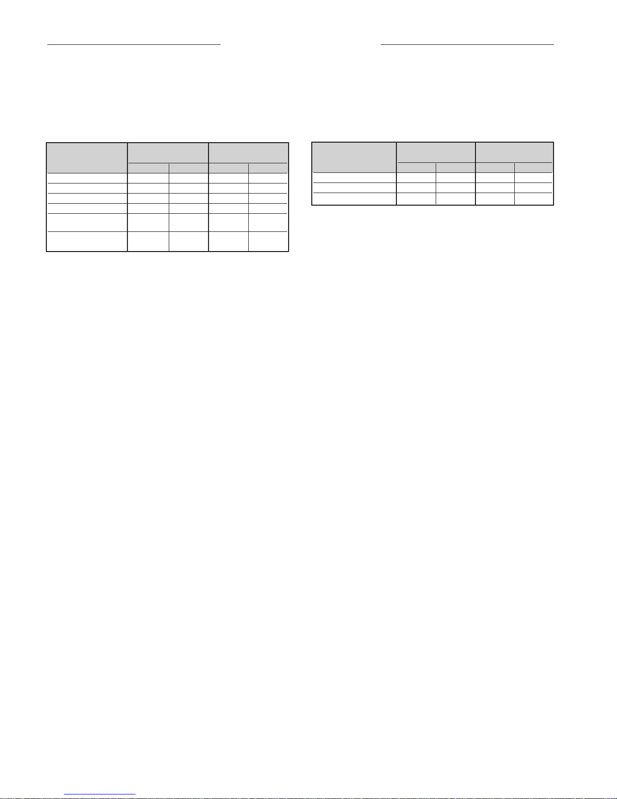
Operating Limits
Environment
This equipment is designed for indoor installation only.
Sheltered locations such as attics, garages, etc., gener
ally will not provide sufficient protection against extremes in
Air limits Water limits
Cooling Heating Cooling Heating
Min. Ambient Air 50˚F/10˚C 50˚F/10˚C 40˚F/5˚C 40˚F/5˚C
Normal Ambient Air 80˚F/27˚C 70˚F/21˚C 80˚F/27˚C 70˚F/21˚C
Max. Ambient Air 100˚F/38˚C 85˚F/29˚C 100˚F/38˚C 85˚F/29˚C
Min. Ent. Air ➀➁ 50˚F/10˚C 50˚F/10˚C 50˚F/10˚C 40˚F/5˚C
Normal Ent. Air, 80/67˚F 70˚F 80/67˚F 70˚F
dw/wb 27/19˚C 21˚C 27/19˚C 21˚C
Max. Ent. Air 100/83˚F 80˚F 100/83˚F 80˚C
db/wb ➀➁ 38/28˚C 27˚C 38/28˚C 27˚C
Standard Range Units
Geothermal Range
Units
Additional Information For Initial Start-up Only
temperature and/or humidity, and equipment performance,
-
reliability, and service life may be adversely affected.
Geothermal Range
Cooling Heating Cooling Heating
Min. Ent. Water ➀➁ 55°F/13°C 55°F/13°C 30°F/-1°C 20°F/-6°C
Normal Ent. Water 85°F/29˚C 70˚F/21°C 77°F/25˚C 40˚F/5°C
Max. Ent. Water ➀➁ 110°F/43˚C 90°F/32°C 110°F/43˚C 90°F/32°C
➀ At ARI flow rate.
➁ Maximum and minimum values may not be combined. If one
value is at maximum or minimum, the other two conditions may
not exceed the normal condition for standard units. Extended
range units may combine any two maximum or minimum conditions, but not more than two, with all other conditions being
normal conditions.
Standard Range Units
Units
Standard Range units CCH & CRH
Units are designed to start-up in an ambient of 50°F (10°C),
with entering air at 50°F (10°C), with entering water at 70°F
(21°C), with both air and water flow rates used in the ISO
13256-1 rating test, for initial start-up in winter.
Note: This is not a normal or continuous operating condition. It is assumed that such a start-up is for the purpose of
bringing the building space up to occupancy temperature.
Geothermal Range units CCW & CRW
Geothermal heat pump units are designed to start-up in an
ambient of 40°F (5°C), with entering air at 40°F (5°C), with
entering water at 25°F (-4°C), with both air and water at flow
rates used in the ISO 13256-1 rating test, for initial start-up
in winter.
Note: This is not a normal or continuous operating condition. It is assumed that such a start-up is for the purpose of
bringing the building space up to occupancy temperature.
Operating voltages
115/60/1 . . . . . . . . . . . . . . . . 104 volts min.; 127 volts max.
208-230/60/1 . . . . . . . . . . . . 197 volts min.; 253 volts max.
265/60/1 . . . . . . . . . . . . . . . . 238 volts min.; 292 volts max.
230/50/1 . . . . . . . . . . . . . . . . 197 volts min.; 253 volts max.
460/60/3 . . . . . . . . . . . . . . . . 414 volts min.; 506 volts max.
380/50/3 . . . . . . . . . . . . . . . . 342 volts min.; 418 volts max.
575/60/3 . . . . . . . . . . . . . . . . 515 volts min.; 632 volts max.
Note: Voltages listed are to show voltage range. However,
units operating with overvoltage and undervoltage for
extended periods of time will experience premature component failure. Three phase system unbalance should not
exceed 2%.
Page 8 / IM 742
Page 9
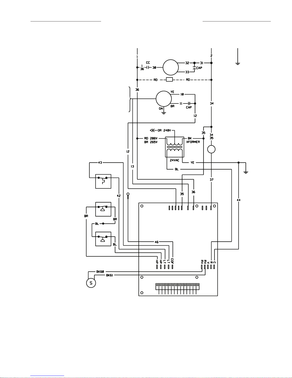
Typical Wiring Diagrams
Fan
Motor
070 - Blk
060 - Blk
048 - Red
042 - Blk
036 - Blk
030 - Blk
Compr
Motor
CC - Compressor Contactor
HTR - Crankcase Heater (Optional)
CAP - Motor Capacitor
Condensate
Sensor
Common
Fan
L1
Compressor
Reversing Valve
Solenoid (24 VAC)
0
W
2
G
W1Y
1
F E
L
U A
P
V
R C
Mark IV
PC
Board
Hi Pressure
Lo Pressure
Lo Temp
Ground
L1 L2
CC
Heater
Figure 8. Typical Mark IV/AC wiring diagram
COMPONENT LAYOUT
➀ COMPRESSOR CONTACTOR
➁ FAN CONTACTOR
➂ TRANSFORMER
➃ PC BOARD
➄ AUXILIARY RELAY
➅ CIRCUIT BREAKER
Notes:
1. Unit is factory wired for 208V operation. If 230V power supply is used,
transformer must be rewired by disconnecting the power lead from the
red transformer primary wire and connecting the power lead to the orange
transformer primary wire. Place an insulation cap on the red transformer
primary wire.
2. All temperature and pressure switches are normally closed.
3. Component layout shown below is typical. Some components may not be
used on this model or voltage.
4. Mark IV/AC controller board contains a static sensitive microprocessor.
Proper grounding of field service personnel should be observed or damage to controller may result.
5. Terminal block on Mark IV/AC board provides 24 VAC at terminals R and
C. All other outputs are 24 VDC.
6. Field supplied relays installed on the input terminals (W1, W2, Y1 or G) may inter-
fere with proper unit operation. Never install relay coils in series with inputs.
7. For more information pertaining to the Mark IV/AC controller, refer to
OM120.
IM 742 / Page 9
Page 10

Figure 9. Typical MicroTech 2000 WSHP unit controller single circuit wiring diagram
Notes:
1. Unit is factory wired for 208V operation. If 230V power supply is used,
transformer must be rewired by disconnecting the power lead from the
red transformer primary wire and connecting the power lead to the orange
transformer primary wire. Place an insulation cap on the red transformer
primary wire.
Page 10 / IM 742
2. All temperature and pressure switches are normally closed.
3. Wires 71 and 72 used only on units with no factory installed options.
Page 11

Figure 10. Typical BACnet® WSHP unit controller
BACnet
Controller
Notes:
1. Unit is factory wired for 208V operation. If 230V power supply is used,
transformer must be rewired by disconnecting the power lead from the
red transformer primary wire and connecting the power lead to the orange
transformer primary wire. Place an insulation cap on the red transformer
primary wire.
2. All temperature and pressure switches are normally closed.
IM 742 / Page 11
Page 12

Unit Operation
Chassis
Ground
Unit
1
Unit
2
Unit
3
To
Additional
Units
Time
Clock
Two types of units are available: Mark IV/AC control units or units equipped with the new MicroTech 2000 Water Source Heat
Pump Controller.
Mark IV/AC Control Units
The Mark IV/AC circuit board is an optional control system with built-in features such as random start, compressor
time delay, night setback, load shed, shutdown, condensate
overflow protection, defrost cycle, brownout, and LED/fault
outputs. Figure 11 shows the LED and fault output sequenc
es.
The unit has been designed for operation with a 24 volt
mercury bulb type wall thermostat or a microelectronic wall
thermostat selected by the manufacturer. Do not operate the
unit with any other type of wall thermostat.
Each unit has a printed circuit board control system. The
low voltage output from the low voltage terminal strip can be
either AC voltage or DC voltage to the wall thermostat. This
is dependent on what terminals you use. R is A/C voltage
output and F is D/C voltage output to the wall stat.
The 24 volt low voltage terminal strip is set up so R-G
or F-G energizes the fan, R-Y1 or F-Y1 energizes the compressor for cooling operation, R-W1 or F-W1 energizes the
compressor and reversing valve for heating operation. The
reversing valve is energized in the heating mode. The circuit
board has a fan interlock circuit to energize the fan whenever the compressor’s on if the thermostat logic fails to do
so.
Remember the output to the wall stat can be AC current
or DC current. Terminal (R) on the wall stat can be con
nected to terminal (R) on the PC board for AC voltage or to
terminal (F) on the PC board for DC voltage.
AC current DC current
R to G = fan only F to G = fan only
R to Y1 = cooling F to Y1 = cooling
R to W1 = heat F to W1 = heat
The Mark IV/AC control board has a lockout circuit to stop
compressor operation if any one of its safety switches opens
(high pressure switch and low pressure switch on units CCH
& CCW 019 thru 060, R-410A), (CRH & CRW 024 thru 070,
R-22). If the low temperature switch opens, the unit will go
into the cooling mode for 60 seconds to defrost any slush
in the water-to-refrigerant heat exchanger. After 60 seconds
the compressor is locked out. If the condensate sensor
detects a filled drain pan, the compressor operation will
be suspended only in the cooling mode. The unit is reset
by opening and closing the disconnect switch on the main
power supply to the unit in the event the unit compressor
operation has been suspended due to low temperature
(freezestat) switch, (high pressure switch, or low pressure
switch on units CCH & CCW 019 thru 060, R-410A), (CRH
& CRW 024 thru 070, R-22). The unit does not have to be
reset on a condensate overflow detection.
The Mark IV/AC control circuit fault output sends a signal
to an LED on a wall thermostat. Figure 11 shows for which
functions the fault output is “on” (sending a signal to the
LED).
Figure 11.
LEDs
Normal Mode Off On Off Off
High Pressure Fault Off Off Flash On
Low Temperature Fault* Flash Off Off On
Condensate Overflow On Dim Off On
Brownout Off Flash Off On On
Load Shed Off Off On Off Off
Unoccupied Mode On On Off Off
Unit Shutdown Off Flash Off On
Indication
Yellow Green Red
Fault
Output
The Remote Reset feature provides the means to
remotely reset automatic lockouts generated by high-pressure and/or low-temperature (in heating) faults. When the
Mark IV board is in automatic lockout due to one of these
faults, and the cause of the fault condition has been allevi-
ated, energizing the O-terminal for 10 seconds or more will
force the Mark IV board to clear the lockout. A unit power
cycle can also be used to clear an automatic lockout if the
conditions causing the fault have been alleviated.
The Fault Retry feature helps to minimize nuisance trips
of automatic lockouts caused by high-pressure and/or lowtemperature (in heating) faults. This feature clears faults the
first two times they occur within a 24-hour period and triggers an automatic lockout on the 3rd fault. The retry count
is reset to zero every 24 hours.
The Mark IV/AC control circuit has built-in night setback
operation. A “grounded’ signal to the “U” terminal on the
low voltage terminal strip puts the unit into the unoccupied
mode for night setback operation. Fan operation terminates
and unit control reverts to the night setback terminal on the
thermostat, W2; day heating and cooling operation is locked
out. R-W2 energizes the compressor and reversing valve for
heating operation. Night setback operation can be overrid
den for two hours by toggling the fan switch (intermittently
closing the R to O terminals) on the Deluxe Auto Changeover
thermostat. Day thermostat setpoints then control the heat
ing and cooling operation. The Mark IV/AC control system
also accommodates load shed and shutdown operation on
receipt of a “grounded” signal to the “L” and “E” terminals,
respectively, on the low voltage terminal strip.
Figure 12.
To activate the unoccupied mode for units on the same clock schedule,
a single wire can be “daisy chained” between units and simply grounded
through the time clock contacts. The same system can also be done to
activate the load shed and unit shutdown modes by running additional
wires between units to ground.
The P and C terminals of the Mark IV/AC board are used
for pump restart. These terminals pass a voltage signal
whenever the unit compressor is turned on. This signal is
detected by a pump restart relay board providing a N.O. or
N.C. set of contacts for heat pump loop circulation pump
control. When used with the Loop Water Controller, the relay
operation accommodates turning off circulation pumps during unoccupied periods with a safety override dependent, at
minimum, on WSHP’s need. The P and C terminals may be
“daisy chained” between 200 units. See page 21.
Field supplied relays installed on the input terminals W1,
W2, Y1, Y2 or G may introduce electrical noise. Never install
relay coils in series with the inputs.
-
-
Page 12 / IM 742
Page 13

MicroTech™ 2000 WSHP Unit Controller
Each McQuay Enfinity R-410A and standard R-22 horizontal
water source heat pump can be equipped with a MicroTech
2000 water source heat pump unit controller. The controller
is microprocessor-based and is designed to communicate
over a LonWorks® (LonTalk® or LonMark® 3.3) communications network. The unit controller is factory programmed
and tested with all the logic required to monitor and control
the unit. The controller sets the unit mode of operation,
monitors water and air temperatures, and can communicate
fault conditions to a LonWorks communications network.
The MicroTech 2000 unit controllers include unit-mounted
return air, discharge air and leaving water temperature sensors. Options include a tenant setpoint adjustment knob
and tenant override button, and the capability of substituting
the return air sensor with a wall-mounted room sensor.
MicroTech 2000™ WSHP unit controller
An amber, on-board status LED aids in diagnostics by
indicating the water source heat pump operating mode and
alarm conditions. If there are no current alarm conditions,
the LED will indicate the unit operating mode as shown in
the table below. If there are one or more alarm conditions
present, the LED will flash to indicate an alarm condition.
MicroTech 2000 heat pumps are designed to be linked
with a centralized building automation system through a
LonWorks communications network for centralized scheduling and management of multiple heat pumps. Wall-mounted
room sensors are available to control the heating and cooling operation of each MicroTech 2000 Water Source Heat
Pump Unit Controller. Available room sensors include: room
sensor with LED status and tenant override button, room
sensor with LED status, timed-override button, and bi-metal
thermostat, room sensor with LED status, timed-override
button, and setpoint adjustment, and room sensor with LED
status, timed-override button, setpoint adjustment and bimetal thermostat.
MicroTech 2000 Unit Controller LED Indication
Status LED State Mode
On Continually Occupied, Occupied Load
Shed
On 1⁄2 sec., Off 5 1⁄2 sec. Unoccupied
On 5 1⁄2 sec., Off 1⁄2 sec. Tenant Override, Override
Load Shed
Flashing Alarm Condition
Each unit controller orchestrates the following unit
operations:
● Enable heating and cooling to maintain setpoint based on
a room sensor.
● Enable fan and compressor operation.
● Monitor all safety controls.
● Monitor discharge air temperature.
● Monitor leaving water temperature.
● Relay status of all vital unit functions.
● Support optional control outputs.
MicroTech 2000™ WSHP unit control box
IM 742 / Page 13
Page 14

BACnet® WSHP Unit Controller
McQuay Enfinity horizontal water source heat pumps
are available with a factory mounted and tested Alerton
BACnet unit controller as a special. The unit controller is
factory programmed and tested with all the logic required
to control the unit, and is designed to communicate over
a BACnet MS/TP communications network to an Alerton
BACtalk building automation system (BAS). Each individual
controller must be programmed with a unique mac address.
Each controller must be physically addressed at the board
using dip switches. The controller operates the compressor,
fan, and reversing valve as required to maintain the space
temperature within the current setpoints. Data regarding
equipment status, water and air temperatures, and fault
conditions can be monitored by an Alerton BACtalk BAS.
Setpoints and other system preferences must be changed
remotely using an Alerton BACtalk workstation or Alerton
service tool software.
The controller makes operational data and commands
available on the Alerton BACtalk network using BACnet
objects and properties. Each heat pump controller connects
to the BACtalk network using a BACnet MS/TP LAN, which
is a simple twisted-pair communications connection that
operates at up to 76.8 Kbps. DIP switches on the control
ler enable the MS/TP MAC address to be set in the range
0-127. A status LED on the unit indicates communication
activity on the MS/TP LAN.
BACnet® WSHP unit controller
Each BACnet-compliant unit includes discharge air and
leaving water temperature sensors, as well as all safety
sensors, signals, and switches. Wall-mounted room sen
sors are available from Alerton to control heating and cooling operation. Available sensors include tamper-resistant
stainless steel wall sensors with optional push-button for
status override; wall-mounted sensors with tenant setpoint
adjustment lever and timed-override button; wall-mounted
sensors with LED status, timed-override button, tenant setpoint adjustment buttons, password-protected field service
access to operational data, and optional humidity sensor;
and wall-mounted sensors with LCD and programmable
operation.
Each BACnet-compliant controller has the following operating features:
● Start-up – The unit will not operate until all the inputs and
safety controls are checked for normal conditions.
● Fan operation – Fan operation can be customized in
software to run continuously during occupied mode, or to
cycle ON or OFF appropriately on a call for heating and
cooling.
● Cooling mode – On a call for cooling, the compressor
and fan start immediately. Compressor run-time is cal
culated as a percent of full cycle time (17 minutes) using
proportional-integral control to maximize efficiency.
● Heating mode – On a call for heating, the compressor
and fan start immediately, and compressor run-time
is calculated as a percent of full cycle time (17 minutes) using proportional-integral control to maximize
efficiency.
● Short Cycle Protection and Random Start – A start
delay of 180 seconds plus the compressor’s MAC
address in seconds prevents short-cycling and simultaneous start-up. A minimum 2-minute on time and
5-minute off time for the compressor further ensures
short-cycle protection.
-
● Occupied Mode – A simple software control signal
from the building automation system or a wall-mounted
unit puts the unit into occupied mode. The unit controls
compressor and fan operation to maintain occupied
setpoints. High and low limits for occupied setpoints are
software configurable.
● Unoccupied Mode – A simple software control signal
from the building automation system or a wall-mounted
unit puts the unit into unoccupied mode for night setback operation. The unit controls compressor and fan
operation to maintain unoccupied heating and cooling
setpoints, which are also software configurable.
● After-hours Override Mode – A simple software control
signal from the building automation system or a wallmounted unit can initiate after-hours heating or cooling
in half-hour increments. Maximum override time is soft
ware configurable up to 9.5 hours. This feature can also
be disabled in software.
● Reversing valve delay – When the compressor turns
off after heating mode, the reversing valve remains
energized for 60 seconds before it returns to the normal
cooling position to eliminate swishing. The reversing
valve energizes 10 seconds before the compressor.
● Load Shed – Load shedding can be orchestrated by the
building automation system using the occupied/unoccu-
-
pied command in software.
● Brownout Protection – An onboard sensor measures
input voltage and suspends compressor and fan operation if the supply voltage drops below 82% of the normal
line voltage for a minimum of 10 seconds, creating an
alarm available in software. The alarm automatically
resets when the supply voltage returns to above 90% of
normal.
Page 14 / IM 742
Page 15

BACnet® WSHP Unit Controller
● Condensate Overflow Protection – A liquid sensor at
the top of the drain pan senses a high water level. Upon
sensing water, cooling operation is suspended, while
heating operation is allowed. The controller creates an
alarm available in software. The alarm automatically
resets when the water level returns to normal.
● Safety Control – The unit monitors refrigerant pressure
and generates separate high-pressure and low-pressure alarms available in software. While either alarm is
active, compressor operation is suspended. In a refriger
ant low-temperature condition, an alarm occurs and the
unit operates in cooling mode for 60 seconds to defrost
the heat exchanger, after which compressor operation is
suspended. These alarms can be reset in software or by
cycling power to the controller.
● Attained Temperature and Water Temperature Alarms
– Attained temperature, water temperature alarms with
software-adjustable setpoints are available in software.
The controller samples supply air and records attained
temperatures for heating and cooling. If after two hours
of operation, the attained temperature does not meet the
software-configurable setpoint for heating or cooling as
appropriate, a software alarm occurs. The alarm auto
matically resets when the attained temperature is within
temperature is within setpoints. The controller also
monitors leaving water temperature. If the leaving water
temperature is outside software-configurable setpoints,
compressor operation is suspended and high or low
water temperature alarms occur. The alarm automatically
resets when the water temperature returns to within 6
deg. F of the setpoint.
● Unit Self-test Mode – While the unit is in occupied
mode, a self-test can be initiated via software. Upon
-
initiation of the test, compressor operation is suspended
for a minimum of five minutes, cooling attained temperatures are cleared, and attained temperature alarms
are cleared. The unit then switches to full heat for four
minutes and then records the attained supply air temperature. Compressor operation is then suspended for
five minutes. The unit then switches to full cooling for
four minutes and the attained supply air temperature
is recorded. Attained temperature alarms are set if the
attained temperatures failed to reach alarm setpoints
during heating or cooling.
-
IM 742 / Page 15
Page 16

WSHP Mark IV/AC Board Low Voltage Terminal Strip (Circuit 1)
O W
2 G
W1 Y1 F E L U A P V R C
W1 Y1 W2 Y2 G
Thermostat Terminals
-
C
+
R
Thermostat Connection Diagrams
WSHP Mark IV/AC Board Low Voltage Terminal Strip (Circuit 1)
O
W1 Y1 F E L U A P V R C
W1 Y1 W2 Y2 G O
Thermostat Terminals
Override (Optional)
-C +R
W2 G
S1
S2
S1
S2
Cut R12 from
circuit board
Remote Senso
r
Thermostat
Wire 1
Wire 2
Mark IV/AC Units – Unit Sizes 007-070
7-Day Programmable Electronic Thermostat (P/N 107095901)
Non-Programmable Electronic Thermostat (P/N 668054201)
Includes Thermostat and Wall Plate.
Refer to the installation, operation & application
guide (LIA217) for thermostat 107095901 installation details
Includes Thermostat and Wall Plate.
Optional Remote Sensor (P/N 667720401)
1. Remove cover from remote sensor housing.
2. Select an appropriate location for mounting the remote
sensor.
3. Mount remote sensor unit using hardware provided.
4. Install two strand shielded wire between remote sensor
and thermostat. Shielded wire must be used.
Do not run remote sensor wire in conduit with other wires.
• Wire 1 should run between the S1 terminal on the ther
mostat and the S1 terminal on the remote sensor
• Wire 2 should run between the S2 terminal on the ther-
mostat and the S2 terminal on the remote sensor
• Connect the shielding of the wire to the S2 terminal on
the thermostat
5. Disable the main sensor (R12) on the thermostat by
cutting it from the circuit board.
Page 16 / IM 742
Notes:
When remote reset of a lockout condition
is required at the wall thermostat, it will be
necessary to utiilize a conductor between
terminal "O" on the wall thermostat to terminal "O" on the Mark IV control board (nonprogrammable stat only).
Refer to the installation, operation & application guide (LIA204-4) for thermostat
668054201 installation details
-
Page 17

MicroTech Wall Sensor – Wiring Diagram
MicroTech Controller
J2
6 7 8 9 10 11 12
62 63 64 65 66 67 68
1 2 3 4 5 6 7
Terminal Board #1
Red
Grn
Wht
Blk
Stranded Wire
(Blk, Wht, Grn, Red)
Wall Sensor
Locate the sensor on a wall where exposure to unrestricted air circulation represents the average temperature of
the space. A common mistake is to mount the sensor too
close to the supply air diffuser in a room. This causes short
cycling of the air conditioning unit and large room temperature swings.
Note:
All sensors have black (common), white (thermistor), and
red (LED) wires. With the tenant override and /or set point
adjustment option, a green wire is provided. The optional
thermometer does not affect wiring.
Refer to IM 529 for detailed installation instructions.
Sensor Tenant Override Setpoint Bi-Metal No. of Conductors
Part No. Switch Adjustment Pot Thermometer Required
107230301 Yes No No 4 + Shield
107230401 Yes No Yes 4 + Shield
107230501 Yes Yes No 4 + Shield
107230601 Yes Yes Yes 4 + Shield
IM 742 / Page 17
Page 18

WSHP Mark IV/AC Board Low Voltage Terminal Strip
O W
2 G
W1 Y1 F E L U A P V R C
1
2
3
Auxiliary Relay
Orange
Yellow
White
WSHP Mark IV/AC Board Low Voltage Terminal Strip
O W
2 G
W1 Y1 F E L U A P V R C
1
2
3
Auxiliary Relay
Orange
Yellow
White
Auxiliary Relay (P/N 106059701)
WSHP Mark IV/AC Board Low Voltage Terminal Strip
O W2 G W1 Y1 F E L U A P V R C
1
2
3
Auxiliary Relay
Orange
Yellow
White
O W2 G W1 Y1 F E L U A P V R C
WSHP Mark IV/AC Board Low Voltage Terminal Strip
O W2 G W1 Y1 F E L U A P V R C
O W2 G W1 Y1 F E L U A P V R C
R
Y
G
W
R
Y
G
W
R
Y
G
W
G W Y R C
G W1 Y1 R Rc C
Thermostat Terminals
Multiple Unit
Control Panel
TB3
TB2
TB1
TB4
WSHP Mark IV/AC Board Low Voltage Terminal Strip
WSHP Mark IV/AC Board Low Voltage Terminal Strip
Operation: In this example the
auxiliary relay contacts can be
used to indicate a fault condition. With the auxiliary relay
connected as shown, the normally open contacts will close
during a fault condition.
Options on Mark IV/AC Units
The auxiliary relay is designed to interface external equipment with the Mark IV/AC board. The auxiliary relay
has been provided with the components necessary
to protect from electrical damage that may occur to the
Mark IV/AC board when using standard off-the-self relays.
The auxiliary relay can be used to provide fault signals,
unit operation signals, or to provide a means for remote
equipment to control the Mark IV/AC board. The orange,
yellow, and white connections are short flying leads
pre-attached to the board. The diagrams shown are some
connection examples.
Operation: In this example the
auxiliary relay contacts can be
used to signal WSHP fan operation to another device. In this
example when the thermostat
energizes the “G” terminal the
auxiliary relay normallyopen
contacts wil close.
Multiple Unit Control (up to 3 units) (P/N 056794201)
This multiple unit control board is an accessory used when
you need to control up to 3-units from a single thermostat.
The board is typically mounted in the unit control box closest to the thermostat. A maximum of 2 boards may be used
together if up to 6-units must be connected and controlled
from a single thermostat.
This version of the board uses VAC relays and should not
be used in combination with any other accessories or equip-
Operation: In this example the
auxiliary relay is used to interface
other control devices to the Mark
IV/AC board. Using the Orange
(-) and White (+) wires, and 24vac
or 24vdc, another device could be
used to start and stop the WSHP
heating sequence.
ment that require VDC connections to the “G”, “W1”, or “Y1”
terminals (i.e. Boilerless System Kit).
The multiple unit control board provides the components
necessary to protect the Mark IV/AC board from electrical
damage that may occur when using standard off-the-shelf
relays.
Do not use the unoccupied (U-terminal) feature with the
multiple unit control board.
Page 18 / IM 742
Page 19
Multiple Unit Control (up to 2 units) (P/N 106059801)
WSHP Mark IV/AC Board Low Voltage Terminal Stri
p
O W 2 G W1 Y1 F E L U A P V R C
R
Y
G
W
L
G W1 Y1 R Rc C
Thermostat Terminals
Multiple Unit
Control Panel
O W 2 G W1 Y1 F E L U A P V R C
G W Y C L
WSHP Mark IV/AC Board Low Voltage Terminal Strip
WSHP Mark IV/AC Board Low Voltage Terminal Strip
O W2 G W1 Y1 F E L U A P V R C
1
2
3
Auxiliary Relay
Orange
Yello w
White
6 3 1
Time Clock
(by others)
Daisy-chain to
additional Mark IV/AC
board “U” terminals
BL
GN
6
3
1
Black to 6
White to 1
Plug
Pins,
Female
Conduit
Anti-Short
Bushing
Connector
Valve
36" (915 mm)
Lead Length
This multiple unit control board is an accessory used when
you need to control up to 2-units from a single thermostat.
The board is typically mounted in the unit control box closest
to the thermostat. The
are short flying leads pre-attached to the board. A maximum
of 3 boards may be used together if up to 4-units must be
connected and controlled from a single thermostat.
This version of the board uses VDC relays and should
not be used in combination with any other accessories
“
G”, “W”, “Y”, “C”, and “L” connections
or equipment that require VAC connections to the “G”, “W1”,
or “Y1” terminals (i.e. Boilerless System Kit). Do not use
the unoccupied (U-terminal) feature with the multiple unit
control board.
The multiple unit control board provides the components
necessary to protect the Mark IV/AC board from electrical
damage that may occur when using standard off-the-shelf
relays.
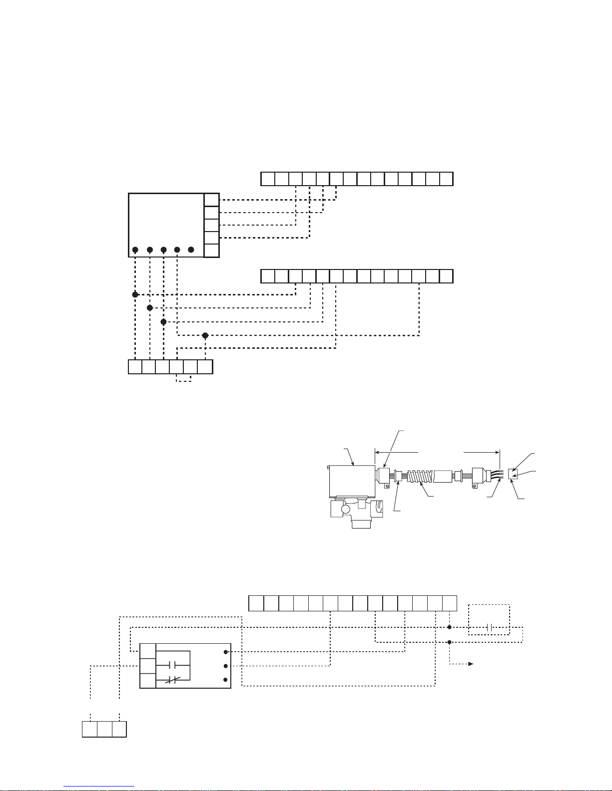
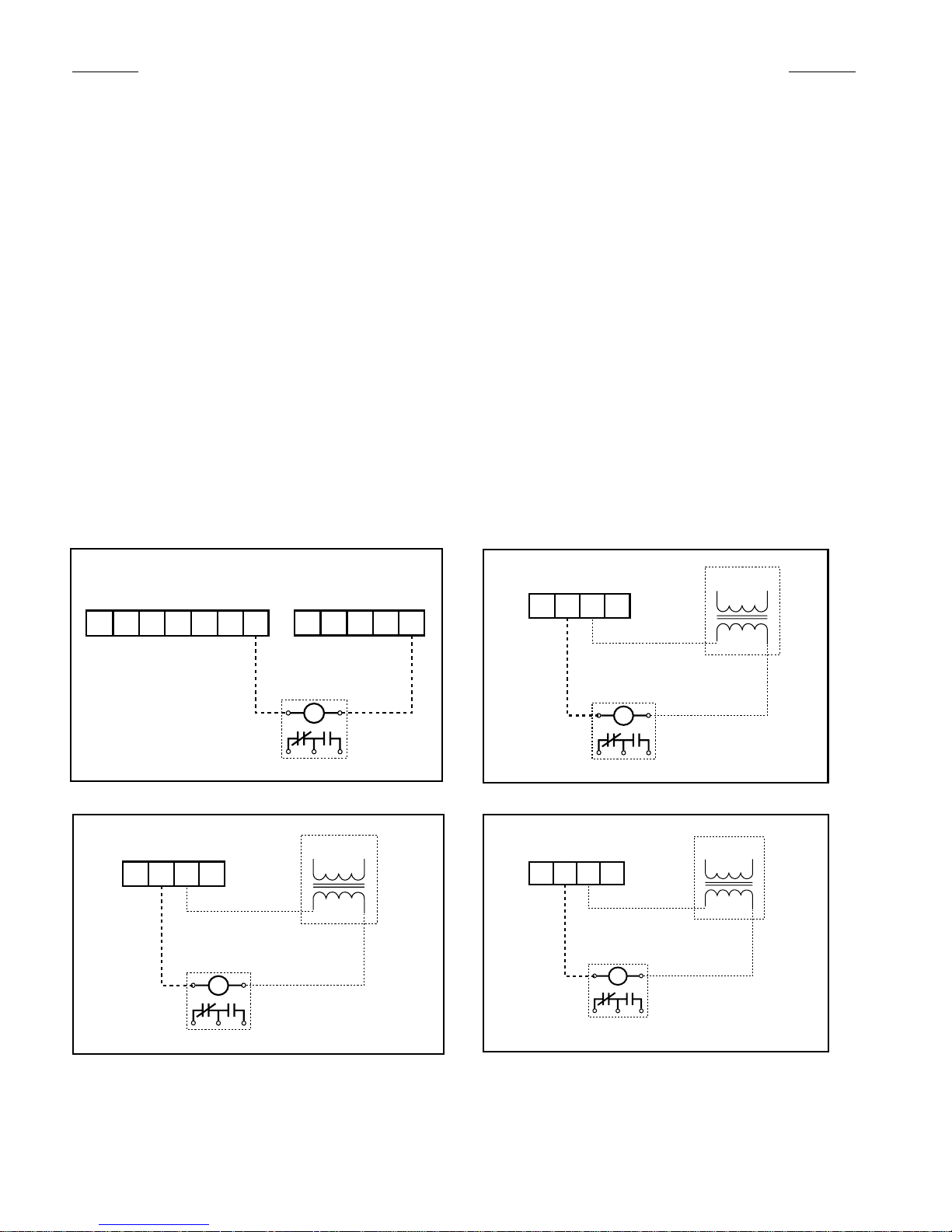
Motorized Valve & Relay for Unit Sizes 007 thru 070
Wired as shown below the motorized valve will open on a
call for compressor operation. Valves for unit sizes 007 to
019 are 1⁄2" power-open spring-return while unit sizes 024
to 070 are 3⁄4" power-open spring return. Other thermostat
combinations may be used. Valve and auxiliary relay are
purchased separately.
Note: The wiring shown below can only be used when the “P”
terminal is not being used as a pump restart signal to other equipment. If the “P” terminal must be used as a pump restart signal to
other equipment, then wire the auxiliary relay’s yellow wire to “Y1”,
white wire to “W1”, and orange wire to “C”, then the valve will
open on a call for occupied heating or cooling from the thermostat.
P/N 060977401 - 1/2" Motorized Valve Kit
P/N 060977301 - 3/4" Motorized Valve Kit
P/N 859004354 - Valve Relay Kit
IM 742 / Page 19
Page 20

Boilerless System Kit (BSK) – P/N 062522204 for sizes 007 - 070
RD
1
2
3
Auxiliary Relay
Orange
Yellow
White
1 2 3 4 5
RD
BR
WH
OR
OR
WH
WH
YE
GR GR
BK
WH
RD
OR
Normal
Override
Pot 1
Boilerless
System
Board
43 Ohm
4-pin
Plug
Water
Temperature
Sensor
Signal to remote
duct heater
control circuit
F L W1 V
Mark IV Board Terminals
9.66
(245 mm)
(007 – 042)
14.50
(368 mm)
(048 – 060)
6.5 (165 mm) (007 – 042)
4.12 (105 mm) (048 – 060)
1.75
(44.5 mm)
The BSK option for use with the Mark IV/AC control board
provides the capability to control a remote duct heater. The
duct heater must be provided with a low voltage control circuit that only requires a set of dry contacts for operation.
The contacts shown on the Boilerless System board (terminals 1, 2, and 3) are used to control the remote duct
heater, the N.O. contacts will close on a call for duct heater
heat. POT1 provides a means to manually adjust the water
temperature setpoint (adjustment range is 43oF to 60oF).
The Normal/Override switch provides a means to manually
force electric heat to always be used in place of heat pump
heat when in the override position (default position is normal
- heat pump heat).
When the water temperature drops below the value of
POT1, then the duct heater will be used instead of heat
pump heat on a call for heat from the low voltage thermostat
(not included).
The BSK field installed kits include the sheet metal enclosure
with cover, wire harness, boilerless system board, auxiliary
relay, and water temperature sensor. When used, one BSK
is required for each unit. To use the BSK kit you attach the
sheet metal enclosure to the unit as shown, route the 4-wire
harness through knockouts and connect to the Mark IV/AC
board, mount and connect and insulate the water temperature sensor on the water supply line, and then connect the
duct heater control contacts to the duct heater control circuit.
If night setback (U-terminal) is used, the duct heater will
respond to the occupied W1 thermostat signal. The load
shed input (L-terminal) cannot be used for other control functions when being used with the BSK.
The BSK is a DC voltage device, when the BSK is used the
thermostat must be wired for VDC operation.
Page 20 / IM 742
When the water temperature drops below the value of POT1,
then the duct heater will be used instead of heat pump
heat on a call for heat from the low voltage thermostat (not
included).
Page 21

Pump Restart Relay Kit P/N 061419001
WSHP Mark IV/AC Board Low Voltage Terminal Strip
Pump
Restart
Relay
7
6
5
4
3
2
1
O W2 G W1 Y1 F E L U A P V R C
Loop
Water
Controller
Terminals
Daisy chain to other Mar
k
IV/AC board “P” and “C”
terminals
64
58
65
WSHP Mark IV/AC Board Low Voltage Terminal Strip (Circuit 1)
Pump
Restart
Relay
7
6
5
4
3
2
1
O W2 G W1 Y1 F E L U A P V R C
Power by
others
Daisy chain to other Mar
k
IV/AC board “P” and “C”
terminals
Used as an option with the Mark IV/AC board, the pump
restart relay kit provides a means to alert the loop water
controller that water flow is required by a WSHP so that the
system pump can be started. This option is typically used in
installations where the pump may be shut off when there is
no need for water flow (i.e. temperature OK, etc.). Typically
only one pump restart relay kit is required per installation
as up to 200 Mark IV/AC boards can be “daisy-chained”
together.
The Mark IV/AC “P” terminal is used to determine WSHP
compressor operation. Wired as shown below, when com
pressor operation is required, the Mark IV/AC “P” terminal
will change state causing a contact closure between terminal
58 and 64 signaling the loop water control (LWC) panel to
restart the loop pump if Off.
The pump restart relay kit is typically mounted within one
WSHP or within the LWC panel, whichever is more convenient, diagrams are provided below for each location. To
install the relay, remove the cover on the double-faced tape
provided on the relay and attach the relay either to the inside
of the LWC panel (adjacent to circuit breaker CB1 and terminal block TB3) or in the WSHP control box (in a convenient
-
location), then wire as shown below.
Wiring Pump Restart Relay when Installed within the LWC Panel
Wiring Pump Restart Relay when Installed within a WSHP Control Box
IM 742 / Page 21
Page 22
Field Installed Options on MicroTech 2000 Units
1 2 3 4 5 6 7
E L U P C
4 3 2 1
(by others)
24VAC
4 3 2 1
(by others)
24VAC
4 3 2 1
(by others)
24VAC
MicroTech 2000 units can provide up to 4-outputs, that can
be configured for any of the following output control signals:
1) Scheduled Output
When using a Network Master Panel (NMP) these out
puts can be assigned to one of 32 available schedules.
The output will energize when the assigned schedule is
occupied and de-energize when in unoccupied. These
outputs could be used to control lights, etc.
2) Auxiliary Heat (Skin Heat)
When using a Loop Water Controller (LWC) the MicroTech
2000 receives loop water temperature information from
the LWC and will use the Auxiliary Heat output for heating when loop water temperature is inappropriate for heat
pump heating. These outputs provide a signal that can be
used to control a remote electric heater. The output will
energize on a call for electric heat and de-energize when
not required.
3) Fresh Air Damper
These outputs provide a signal that can be used to control
a remote fresh air damper. The output will energize when
the unit fan is energized and de-energize when the unit
fan is de-energized.
1st Control Signal Output
(Located externally on the WSHP chassis)
Terminal Boards
4) Motorized Water Valve
These outputs provide control for a motorized water valve
that can be used to stop or divert flow away from the
-
WSHP when compressor operation is not needed. The
output will be energized when compressor operation is
required.
If more than one of the above control signals is required on
a single WSHP, the MicroTech 2000 Auxiliary Module Kit
(1077311001) must be used and these additional output control signals will be connected to the Auxiliary board. 1-circuit
units can provide up to 4-outputs.
If the Auxiliary board is added in the field to provide additional outputs it will need to be mounted within the WSHP control
box so that J1 on the Auxiliary board can be connected to J6
on the MicroTech 2000 board without exceeding a maximum
wire length of 10".
Also, each output is by default configured to “none” and must
be field set to one of the four signal types listed above using
the Monitor software, cable, and a PC communicating to the
unit through an MCG panel.
2nd Control Signal Output
Terminals Located on
Microtech 2000 Auxiliary Board
J6
IMPORTANT:
To use onboard 24VAC,
change the jumper PF1 on the
MicroTech 2000 controller from
factory default pins 1 and 2 to
pins 2 and 3.
3rd Control Signal Output
Terminals Located on
Microtech 2000 Auxiliary Board
J7
Use contacts as needed for option
24VAC
Pilot Duty Relay
(by others)
24VAC
Pilot Duty Relay
(by others)
Pilot Duty Relay
Use contacts as needed for option
4th Control Signal Output
Terminals Located on
Microtech 2000 Auxiliary Board
J10
Pilot Duty Relay
(by others)
Use contacts as needed for option
24VAC
(by others)
24VAC
Page 22 / IM 742
Page 23
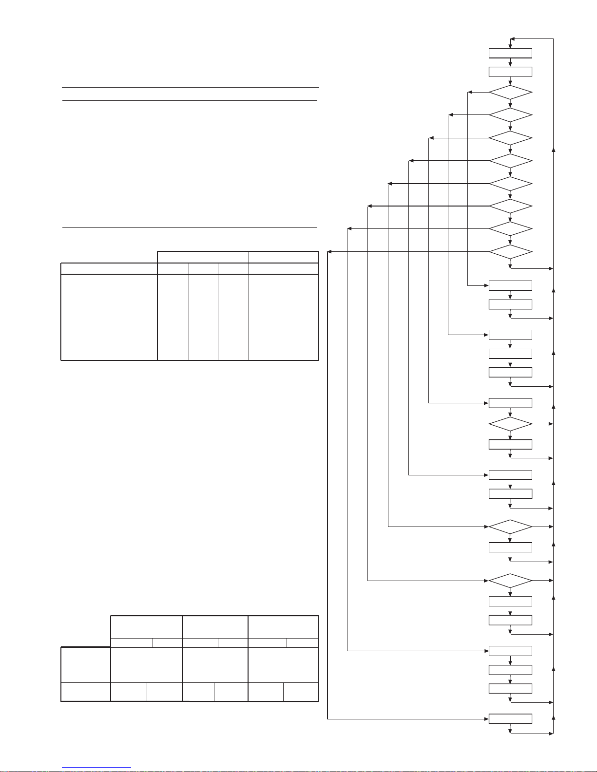
Read Outputs
Check Timers
Hi
Pres. Sw ?
Brown Out ?
Low Temp SW?
Lo Shed ?
N S B ?
Cond. Overflw?
R - W 1 ?
R -Y 1 ?
Stop Comp.
Flash Red LED
Stop Fan
Flash Green LED
Stop Comp.
Htg Mode?
Stop Comp.
Fla sh Yel low LE D
Stop Comp.
Turn On Red LED
R - W 2 ?
Start Comp.
Cooling Mode
Stop Comp.
Reversing Valve On
Time Delay
Start Comp.
Start Comp.
No
No
No
Ye s
No
No
No
No
No
No
No
No
Turn on Yellow LED
Yes
Yes
Yes
Yes
Yes
Yes
Yes
Yes
Yes
Mark IV/AC Sequence of Operation
14-Position Terminal Strip
Pin Designation Description
1 C Transformer ground (Ovac)
2 R Transformer supply (24vac)
3 V -DC power connection
4 P Pump request output
5 A Alarm fault output
6 U Unoccupied input
7 L Load shed input
8 E Remote shutdown input
9 F +DC power connection
10 Y1 Occupied cooling mode input
11 W1 Occupied heating mode input
12 G Fan only input
13 W2 Unoccupied heating mode input
14 O` Tenant override input
LED Status and Fault Output Status
Board Status LED’s Fault Output
Mode Yellow Green Red Terminal A
Occupied Off On Off Energized
Unoccupied On On Of Energized
Load Shed Off Off On Energized
Condensate Overflow On Dim Off De-Energized
High/Low Pressure Fault Off Off Flash De-Energized
Low Temperature Fault* Flash Off Off De-Energized
Brownout Off Flash Off De-Energized
Emergency Shutdown Off Flash Off De-Energized
*in heating mode only
Note: The fault output is energized when no faults exist. The fault ouput is
de-energized during faults and when unit power is off.
General Use and Information
The Mark IV/AC control board is provided with three drive terminals, R(24vac),
F(24vdc), and C(Ovac) that can be used by the end user to drive the thermostat
inputs (G, Y1, W1, and W2) and control inputs (U, L, E, and O). Any combination of
a single board drive terminal (R, F, or C) may be used to operate the Mark IV/AC
boards control or thermostat inputs. However, only one drive terminal (R, F, or C)
can be connected to any individual input terminal or damage will occur. Some of the
control inputs are used within the Water Source Heat Pump and not accessible to the
end user. For example, HP, LT, and COF are not available for use by the end user.
Typically the Mark IV/AC board’s R(24vac) terminal is used to drive the board’s
thermostat inputs and control inputs by connecting it to the R terminal of an industry
standard thermostat. The control outputs of the standard thermostat are then con
nected to the Mark IV/AC board thermostat inputs and control inputs as needed. Any
remaining board input(s) may be operated by additional thermostat outputs or remote
relays (dry contacts only).
All Mark IV/AC board inputs must be operated by dry contacts powered by the control board’s power terminals. No solid state devices (Triacs) may be used to operate
Mark IV/AC board inputs. No outside power source may be used to operate Mark
IV/AC board inputs.
Using Drive Using Drive Using Drive
Terminal R (24vac) Terminal F (24vdc) Terminal C (ground)
De-engergized Energized D-energized Energized De-energized Energized
Place the Meters
Red (+) Lead on
Input to be
checked
U, L, E, Y1, W1, 10 to 22 to
G. W2. P 14vac 26vac 33vdc 14vac 26vac
Place the Meters Place the Meters Place the Meters
on Black (-) Lead Black (-) Lead Black (-) Lead
on C on V on R
Ovdc
30 to 10 to 22 to
-
IM 742 / Page 23
Page 24
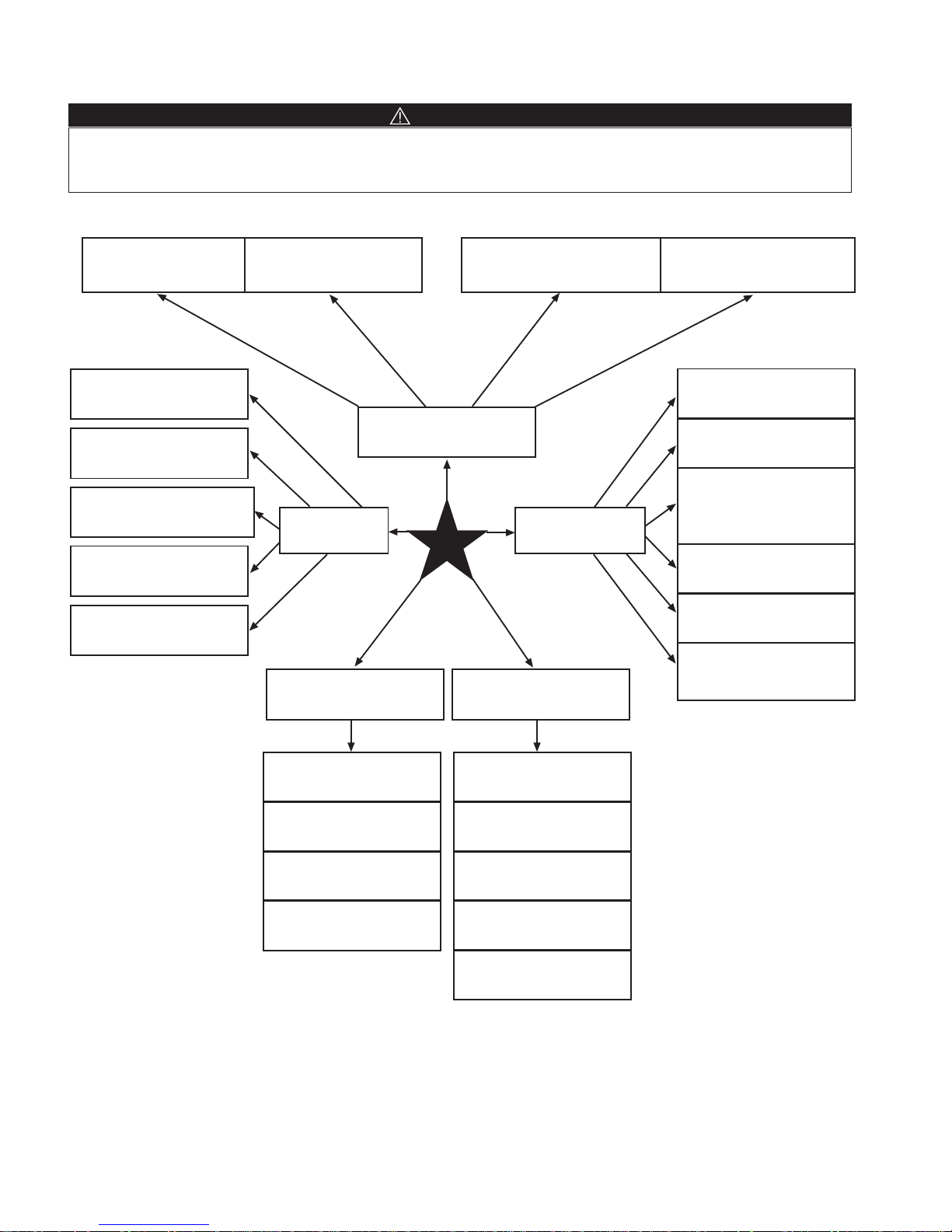
Troubleshooting Water Source Heat Pump
Low Voltage, check power
supply voltage
Fuse may be blown, circuit
breaker is open
Wires may be loose or broken.
Replace or retighten wires
Unit Control, check thermostat
for correct wiring or bad thermostat
Neither Fan, nor
Compressor Runs
Unit
Compressor runs
in short cycle
Fan operates,
Compressor does not
Compressor attempts to start
but does not
Insufficient cooling or heating
Check compressor wiring for
defective wiring or loose
connection
Check thermostat for improper
location
Check for defective compressor
internal windings with ohm meter
Check for bad compressor
capacitor
Check for lock rotor amp draw
Check for proper air flow. Filter
could be dirty
Check blower assembly for
dirt or bad fan motor capacity
Check for low refrigerant charge
Check amp draw on blower
assembly
Check capacitor
Check wiring - loose or broken
and check for bad
connection
Hi pressure lockout A. Cool mode, check water flow
B. Heating mode, check air flow
C. Check reversing valve for
proper valve position
Check compressor overload
make sure it is closed
Check compressor to ground,
or for internal short to ground.
Compressor winding may be
open. Check continuity with
ohm meter
Check wiring - loose or broken
and check for bad
connection
Check relays and contacts,
also capacitor and wiring
Check high pressure switch
and low temperature switch to
see if unit is cycling on the safety
Check to see if the reversing
valve is not hung up and is
operating correctly
Check condensate overflow
switch in cool mode of operation
DANGER
To avoid electrical shock, personal injury or death, be sure that field wiring complies with local and national fire, safety, and electrical
codes, and voltage to the system is within the limits shown in the job-specific drawings and unit electrical data plate(s).
Power supply to unit must be disconnected when making field connections. To avoid electrical shock, personal injury or death, be sure
to rigorously adhere to field wiring procedures regarding proper lockout and tagout of components.
Page 24 / IM 742
Page 25

The in and outs of Enfinity™ R-410A
Troubleshooting
Refrigerant 410A is a non-ozone depleting blend of two
refrigerants HFC-125 and HFC-32 in a fifty percent mixture. Refrigerant 410A exhibits higher operating pressure
and refrigeration capacity than R-22. R-410A refrigerant
is intended for use in new air conditioning application that
has traditionally been serviced by HCFC-22 or R-22. Due
to higher capacity and pressure of R-410A, it is not recommended as a retrofit to existing R-22 systems.
Although R-410A is non-flammable at ambient temperature and atmosphere pressure, it can become combustible under pressure when mixed with air. (NOTE:
R-410A should not be mixed with air under pressure for
leak testing. Pressure mixtures of dry nitrogen and R-410A
can be used for leak testing.)
Lubrication
R410A should be used only with polyolester (POE) oil. The
HFC refrigerant components in R-410A will not be compatible with mineral oil or alkylbenzene lubricants. R-410A systems will be charged with the OEM recommended lubricant,
ready for use with R-410A.
Charging
Due to the zeotropic nature of R-410A, it should be charged
as a liquid. In situations where vapor is normally charged
into a system, a valve should be installed in the charging
line to flash the liquid to vapor while charging.
Warning
It is very important to make certain that the recycle or recovery equipment used is designed for R-410A. The pressure
of R-410A refrigerant is approximately 60 percent greater
than that of R-22. Pressure gauges require a range up to
800 PSIG high side and 250 PSIG low side. Recovery cyl
inders require a 400 PSIG rating – do not put R-410A in a
300 PSIG rated cylinder.
(NOTE: because a water source heat pump operates under
a wide range of water and air temperatures, the values
printed below are to be taken as suggested pressure and
temperatures.) All McQuay water source heat pumps are
designed for commercial use. The units are designed for
the cooling mode of operation and fail safe to cooling.
The revising valve is energized for the heating mode of
operation.
Superheat Head Pressure Water Delta T
8 to 14 degrees 335-355 PSIG 10° to 12°
All information above is based on ISO standard 13256-1
and are tested at these conditions.
-
Troubleshooting Refrigeration Circuit
Air Water Safety
Symptom
Pressure Pressure Amp Draw Heat Differential Differential Out
Charge
Undercharge System Low Low Low High Low Low Low Low Pressure
(Possible Leak)
Overcharge System
Pressure
Low Air Flow Heating
Low Air Flow Cooling Low Low Low
Low Water Flow Heating Low Low
Low Water Flow Cooling High High High High Low Low High High Pressure
High Air Flow Heating Low Low Low Low High Low Low Low Temp
High Air Flow Cooling Low High Normal High Low Low Normal High Pressure
High Water Flow Heating Normal Low Normal High Normal Normal Low High Pressure
High Water Flow Cooling Low Low Low Low High Normal Low Low Temp
Head Suction Compressor Super
High High High Normal High Normal High
High High High
Low
Normal
Low
Normal
High
Low
Normal
Normal
Subcooling
High High Low Low Temp
High Low High Low Temp
Temp (loops) Temp Lock
Normal
Low
Low High Low High Pressure
TXV Restricted High Low High High Low Low
Normal
Low
IM 742 / Page 25
Page 26

Typical Refrigeration Cycles
Cooling Mode – (Single Circuit Only Shown)
Return Air
Thermal
Expansion Valve
Co-Axial Heat
Exchanger
Coil – Air to Refrigerant
Heat Exchanger
Blower
Reversing Valve
Conditioned Air – (Cooling)
Water In
Water Out
Sensing Bulb and
Capillary Tube
Compressor
Cooling Refrigeration Cycle
When the wall thermostat is calling for COOLING, the reversing valve directs the flow of the refrigerant, a hot gas, leaving the
compressor to the water-to-refrigerant heat exchanger. Here the heat is removed by the water and the hot gas condenses to
become a liquid. The liquid then flows through a thermal expansion metering system to the air-to-refrigerant heat exchanger
coil. The liquid then evaporates becoming a gas, at the same time absorbing heat and cooling the air passing over the surfaces
of the coil. The refrigerant then flows as a low pressure gas through the reversing valve and back to the suction side of the
compressor to complete the cycle.
Heating Mode – (Single Circuit Only Shown)
Return Air
Thermal
Expansion Valve
Co-Axial Heat
Exchanger
Coil – Air to Refrigerant
Heat Exchanger
Blower
Conditioned Air – (Heating)
Heating Refrigeration Cycle
When the wall thermostat is calling for HEATING, the reversing valve directs the flow of the refrigerant, a hot gas, leaving the
compressor to the air-to-refrigerant heat exchanger coil. Here the heat is removed by the air passing over the surfaces of the
coil and the hot gas condenses to become a liquid. The liquid then flows through a capillary thermal expansion metering system
to the water-to-refrigerant heat exchanger. The liquid then evaporates becoming a gas, at the same time absorbing heat and
cooling the water. The refrigerant then flows as a low pressure gas through the reversing valve and back to the suction side of
the compressor to complete the cycle.
Page 26 / IM 742
Reversing Valve
Water In
Water Out
Sensing Bulb
and Capillary Tube
Compressor
Page 27

General Maintenance
1. Normal maintenance on all conditioners is generally limited to filter changes. Motors used with WSHP unit size
007 through 070 are provided with permanently lubricated
motors and require no oiling even though oil caps may be
provided.
2. Filter changes are required at regular intervals. The time
period between changes will depend upon the project
requirements. Some applications such as motels pro
duce a lot of lint from carpeting and linen changes, and
will require more frequent filter changes. It is suggested
that the filter be checked at 60-day intervals for the first
year until experience is acquired. If light cannot be seen
through the filter when held up to sunlight or a bright light,
it should be changed. A more critical standard may be
desirable.
3. The condensate drain pan should be checked annually
and cleaned and flushed as required.
4. Recording of performance measurements of volts, amps,
and water temperature differences (both heating and
cooling) is recommended. A comparison of logged data
with start-up and other annual data is useful as an indica-
-
tor of general equipment condition.
5. Periodic lockouts almost always are caused by air or
water problems. The lockout (shutdown) of the condi
tioner is a normal protective result. Check for dirt in the
water system, water flow rates, water temperatures,
airflow rates (may be dirty filter), and air temperatures. If
the lockout occurs in the morning following a return from
night setback, entering air below machine limits may be
the cause.
-
IM 742 / Page 27
Page 28

®
McQuay Training and Development
Now that you have made an investment in modern, efficient McQuay equipment, its care should
be a high priority. For training information on all McQuay HVAC products, please visit us at www.
mcquay.com and click on training, or call 540-248-9646 and ask for the Training Department.
Warranty
All McQuay equipment is sold pursuant to its standard terms and conditions of sale, including Limited
Product Warranty. Consult your local McQuay Representative for warranty details. Refer to Form
933-43285Y. To find your local McQuay Representative, go to www.mcquay.com.
This document contains the most current product information as of this printing. For the most up-to-date
product information, please go to www.mcquay.com.
Products Manufactured in an ISO Certified Facility.
©2007 McQuay International • 800.432.1342 • www.mcquay.com IM 742 (Rev. 9-07)
 Loading...