

Page 1
INVERTER CEILING CASSETTE
SPLIT TYPE AIR CONDITIONER
(E Series)
© 2009 McQuay International
INSTALLATION MANUAL
IM-5CKYER-1009(1)-McQuay
Part Number: R08019034195A
Page 2

Page 3
1-1
English
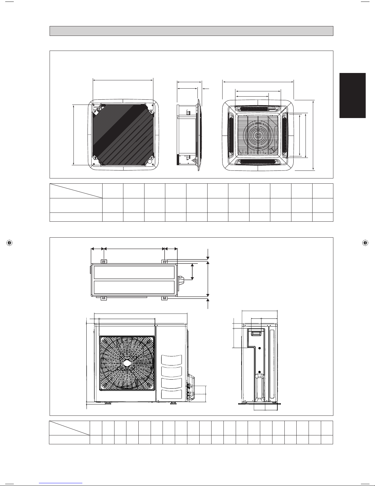
Indoor Unit 5CKY20/25E/ER & 5CKY28/40/50ER
A
B
C
D
E
F
H
K
J
I
G
Original Instruction
All dimensions are in mm
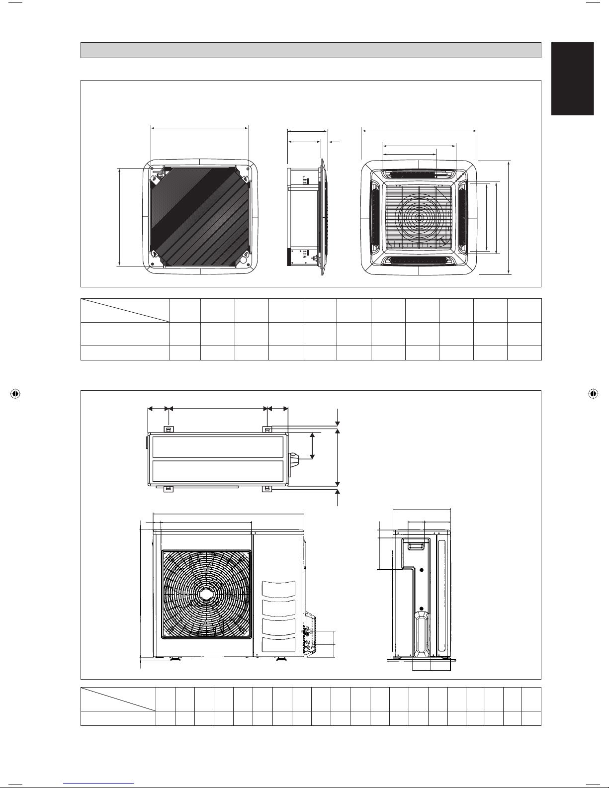
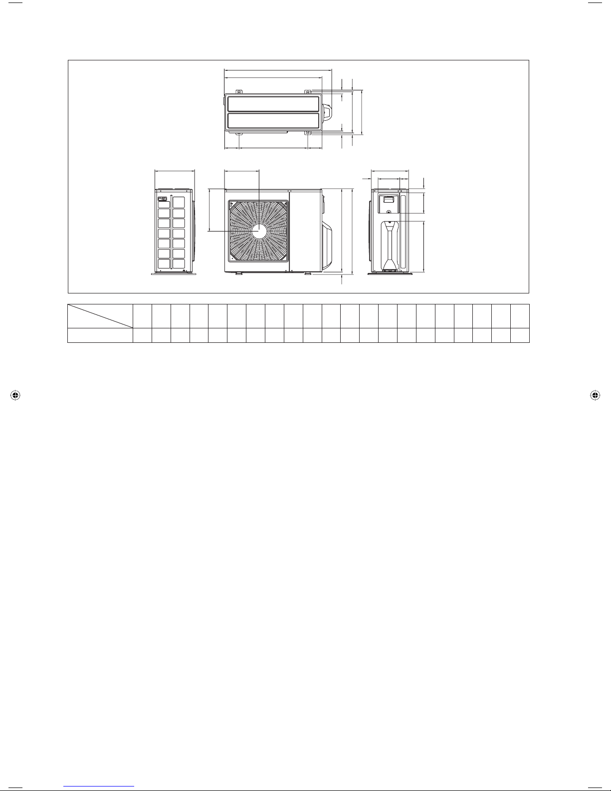
OUTLINE AND DIMENSIONS
Dimension
Model
AB C D E F GH I J K
5CKY20/25E/ER
5CKY28ER
820 820 340 300 40 990 990 627 627 607 430
5CKY40/50ER 820 820 375 335 40 990 990 627 627 607 430
Outdoor Unit 5SLY20/25C/CR
All dimensions are in mm
N
L
KL
TN
M
A
D
O
PBQ
RS
C
HG
FE
IJ
Dimension
Model
ABCDE FGH I JKLMNOPQRST
5SLY20/25C/CR 855 730 328 513 182 44 93 149 101 113 603 126 164 15 47 3 23 73 75 362
Page 4

1-2
Outdoor Unit 5SLY28CR
A
D
K
E
S
T
S
T
GRR
OMN
H
P
Q
L
C
FU
J
B
I
Dimension
Model
ABCDE FGH I JKLMNOPQRSTU
5SLY28CR 940 348 753 855 392 733 603 328 303 370 362 448 190 80 58 180 32 126 32 15 23
Page 5
1-3
English
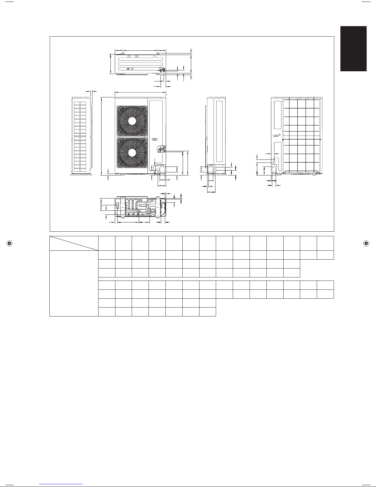
Outdoor Unit 5SLY40/50FR
AB AC AD
AE
AFAG
AH
AI
AA
AJ
AK
A
C
B
D
F
E
L
M
KJ
NO
Q
P
R
S
T
U
V
W
Z
X
Y
AT
AS
H
G
AU
AP
AQ
AO
AL
AM
AN
Dimension
Model
ABCDE FGH I JKLMN
5SLY40/50FR
900 1374 30 24 60 89 142 89 19 54 95 423 430 95
OPQRSTUVWXYZ
54 19 89 145 84 55 55 223 148 13 52 67
AA AB AC AD AE AF AG AH AI AJ AK AL AM AN
350 140 620 140 30 320 30 59 43 40 94 117 102 70
AO AP AQ AR AS AT AU
45 376 191 70 58 16 16
All dimensions are in mm
AR
I
Page 6
1-4
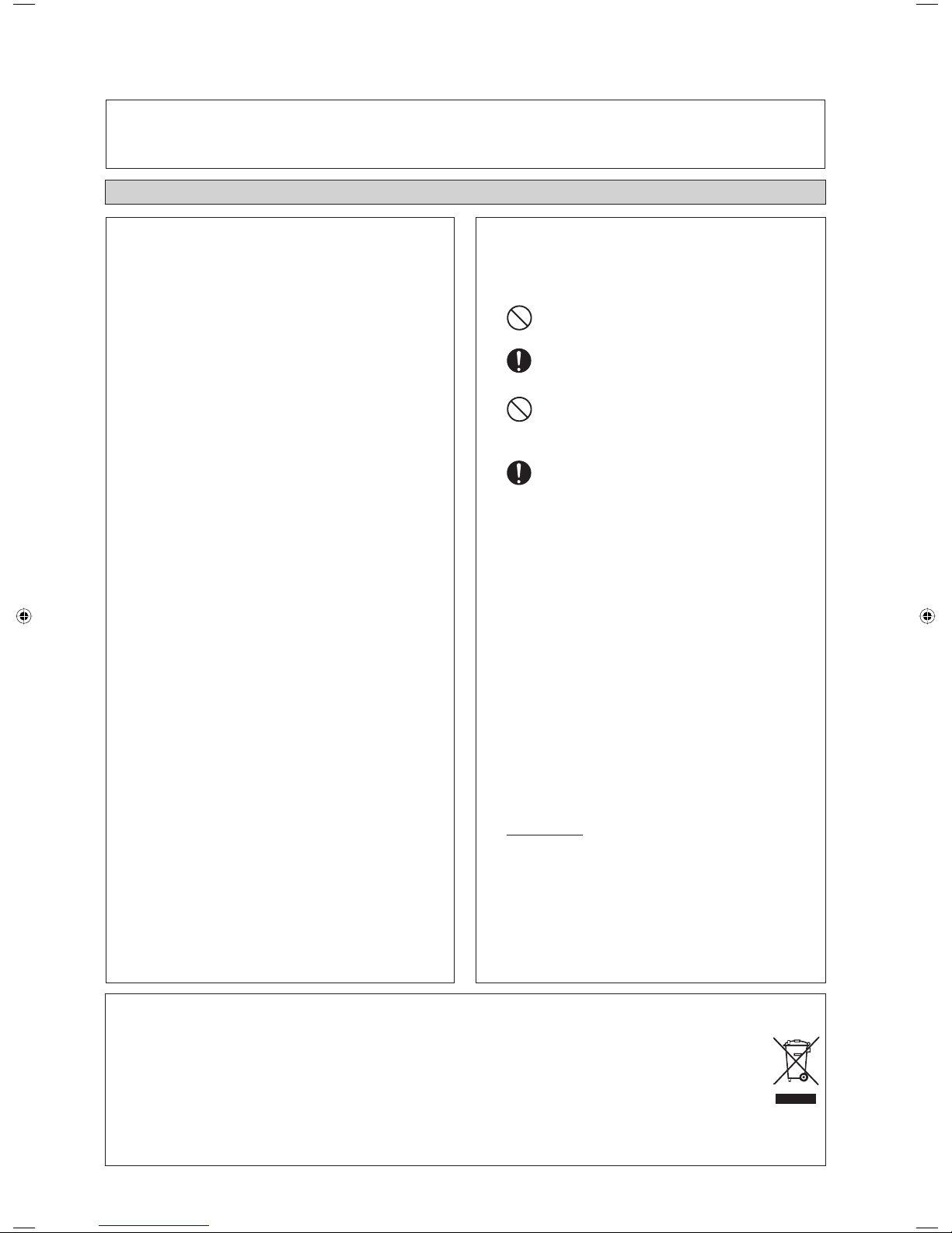
SAFETY PRECAUTIONS
! WARNING ! CAUTION
•
Installation and maintenance should be performed by qualifi ed
persons who are familiar with local code and regulation, and
experienced with this type of appliance.
•
All fi eld wiring must be installed in accordance with the national
wiring regulation.
•
Ensure that the rated voltage of the unit corresponds to that of
the name plate before commencing wiring work according to
the wiring diagram.
•
The unit must be GROUNDED to prevent possible hazard due
to insulation failure.
•
All electrical wiring must not touch the refrigerant piping, or
any moving parts of the fan motors.
•
Confi rm that the unit has been switched OFF before installing
or servicing the unit.
•
Disconnect from the main power supply before servicing the
air conditioner unit.
•
DO NOT pull out the power cord when the power is ON. This
may cause serious electrical shocks which may result in fi re
hazards.
•
Keep the indoor and outdoor units, power cable and transmission
wiring, at least 1m from TVs and radios, to prevent distorted
pictures and static. {Depending on the type and source of the
electrical waves, static may be heard even when more than 1m
away}.
Please take note of the following important points when
installing.
•
Do not install the unit where leakage of fl ammable gas may
occur.
If gas leaks and accumulates around the unit, it may cause
fi re ignition.
•
Ensure that drainage piping is connected properly.
If the drainage piping is not connected properly, it may
cause water leakage which will dampen the furniture.
•
Do not overcharge the unit.
This unit is factory pre-charged.
Overcharge will cause over-current or damage to the
compressor.
•
Ensure that the unitʼs panel is closed after service or
installation.
Unsecured panels will cause the unit to operate noisily.
•
Sharp edges and coil surfaces are potential locations which
may cause injury hazards.
Avoid from being in contact with these places.
•
Before turning off the power supply, set the remote
controllerʼs ON/OFF switch to the “OFF” position to
prevent the nuisance tripping of the unit. If this is not done,
the unitʼs fans will start turning automatically when power
resumes, posing a hazard to service personnel or the user.
•
Do not operate any heating apparatus too close to the air
conditioner unit. This may cause the plastic panel to melt or
deform as a result of the excessive heat.
•
Do not install the units at or near doorway.
•
Do not operate any heating apparatus too close to the air
conditioner unit or use in room where mineral oil, oil vapour
or oil steam exist, this may cause plastic part to melt or
deform as a result of excessive heat or chemical reaction.
•
When the unit is used in kitchen, keep fl our away from going
into suction of the unit.
•
This unit is not suitable for factory used where cutting oil
mist or iron powder exist or voltage fl uctuates greatly.
•
Do not install the units at area like hot spring or oil refi nery
plant where sulphide gas exists.
•
Ensure the color of wires of the outdoor unit and the
terminal markings are same to the indoors
respectively.
•
IMPORTANT: DO NOT INSTALL OR USE THE AIR
CONDITIONER UNIT IN A LAUNDRY ROOM.
•
Donʼt use joined and twisted wires for incoming power
supply.
•
Avoid direct contact of any coil treatment cleaners on plastic
part. This may cause plastic part to deform as a result of
chemical reaction.
•
For any enquiries on spare parts please contact your
authorized dealer.
•
The equipment is not intended for use in a potentially
explosive atmosphere.
This manual provides the procedures of installation to ensure a safe and good standard of operation for the air conditioner unit.
Special adjustment may be necessary to suit local requirements.
Before using your air conditioner, please read this instruction manual carefully and keep it for future reference.
This appliance is intended to be used by expert or trained users in shops, in light industry and on farms, or for commercial use by lay persons.
INSTALLATION MANUAL
NOTICE
Disposal requirements
Your air conditioning product is marked with this symbol. This means that electrical and electronic products shall not be mixed with unsorted
household waste.
Do not try to dismantle the system yourself: the dismantling of the air conditioning system, treatment of the refrigerant, of oil and of other parts
must be done by a qualifi ed installer in accordance with relevant local and national legislation.
Air conditioners must be treated at a specialized treatment facility for re-use, recycling and recovery. By ensuring this product is disposed of
correctly, you will help to prevent potential negative consequences for the environment and human health. Please contact the installer or local
authority for more information.
Batteries must be removed from the remote controller and disposed of separately in accordance with relevant local and national legislation.
Page 7
1-5
English
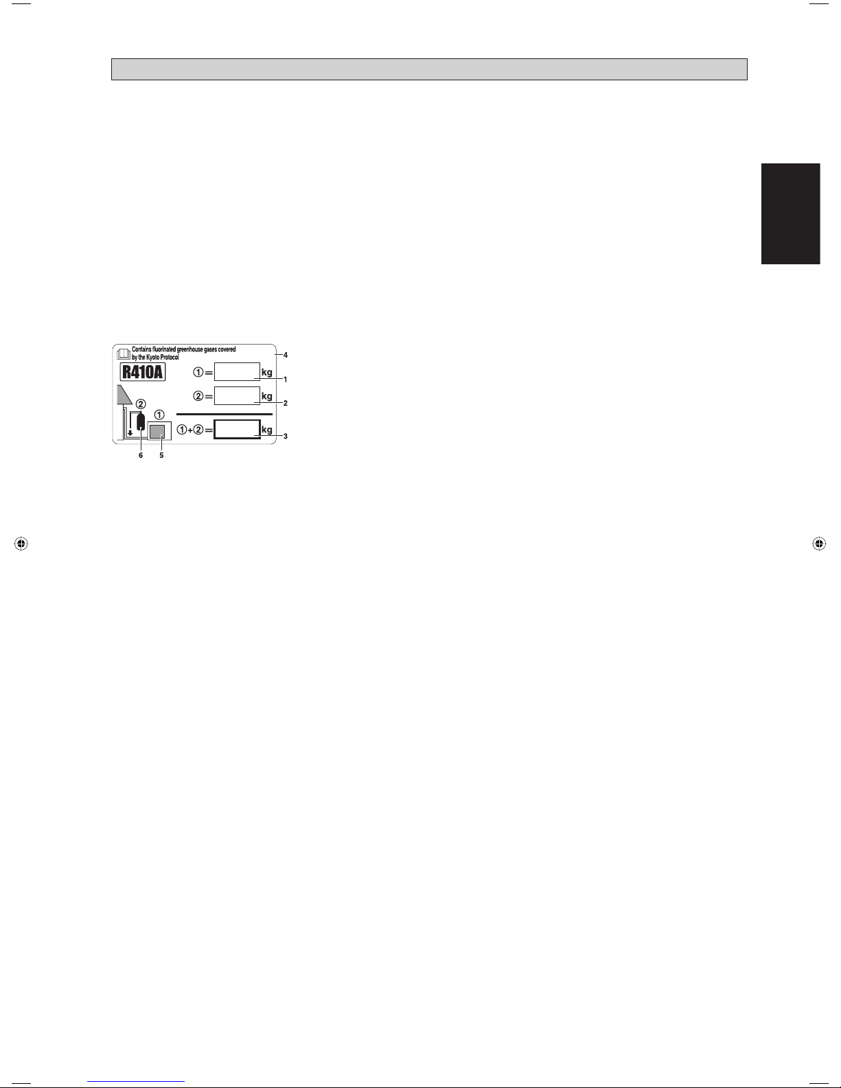
IMPORTANT
Important information regarding the refrigerant used
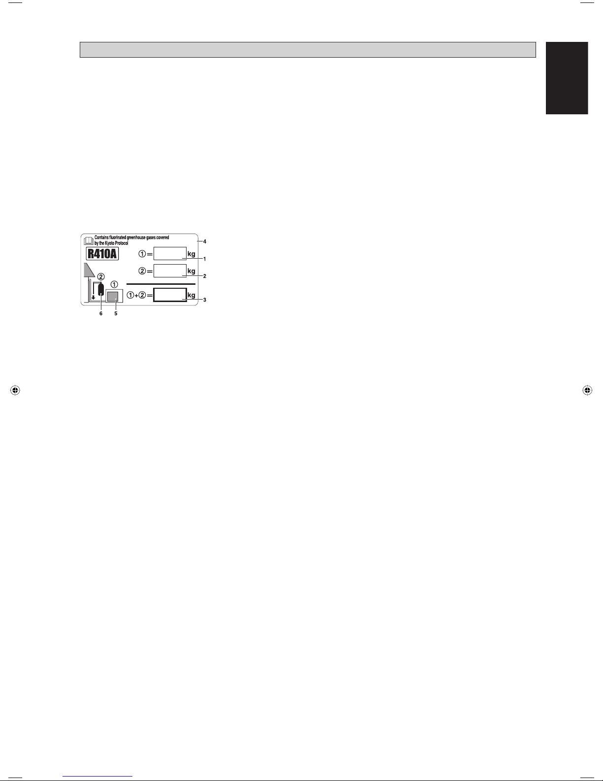
This product contains fl uorinated greenhouse gases covered by the Kyoto Protocol.
Do not vent gases into the atmosphere.
Refrigerant type: R410A
GWP
(1)
value: 1975
(1)
GWP = global warming potential
Please fi ll in with indelible ink,
n 1 the factory refrigerant charge of the product,
n 2 the additional refrigerant amount charged in the fi eld and
n 1 + 2 the total refrigerant charge
on the refrigerant charge label supplied with the product.
The fi lled out label must be adhered in the proximity of the product charging port (e.g. onto the inside of the service cover).
1 factory refrigerant charge of the product:
see unit name plate
(2)
2 additional refrigerant amount charged in the fi eld
3 total refrigerant charge
4 contains fl uorinated greenhouse gases covered by the Kyoto Protocol
5 outdoor unit
6 refrigerant cylinder and manifold for charging
(2)
In case of multiple indoor systems, only 1 label must be adhered*, mentioning the total factory refrigerant charge of all
indoor units connected in the refrigerant system.
Periodical inspections for refrigerant leaks may be required depending on European or local legislation. Please contact your
local dealer for more information.
* on the outdoor unit
Page 8

1-6
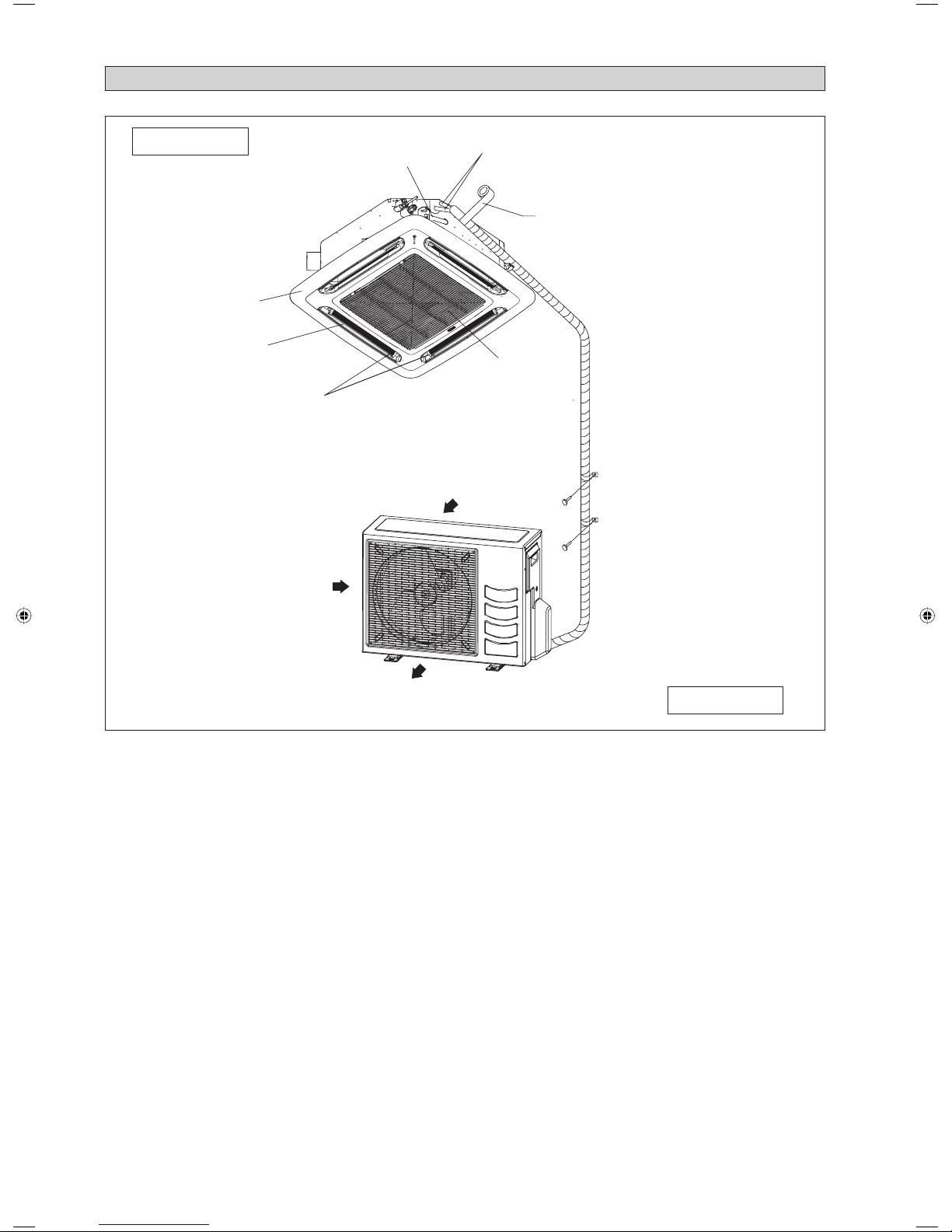
INSTALLATION DIAGRAM
Drain Piping
Front Panel
Air Filter
(behind the grille)
Air Intake Grille
Air Discharge
Air Discharge Louver
Air Intake
Air Intake
Thermal Insulation
Wrap the insulated pipe with the
fi nishing tape from bottom to top
Indoor Unit
Outdoor Unit
Page 9
1-7
English
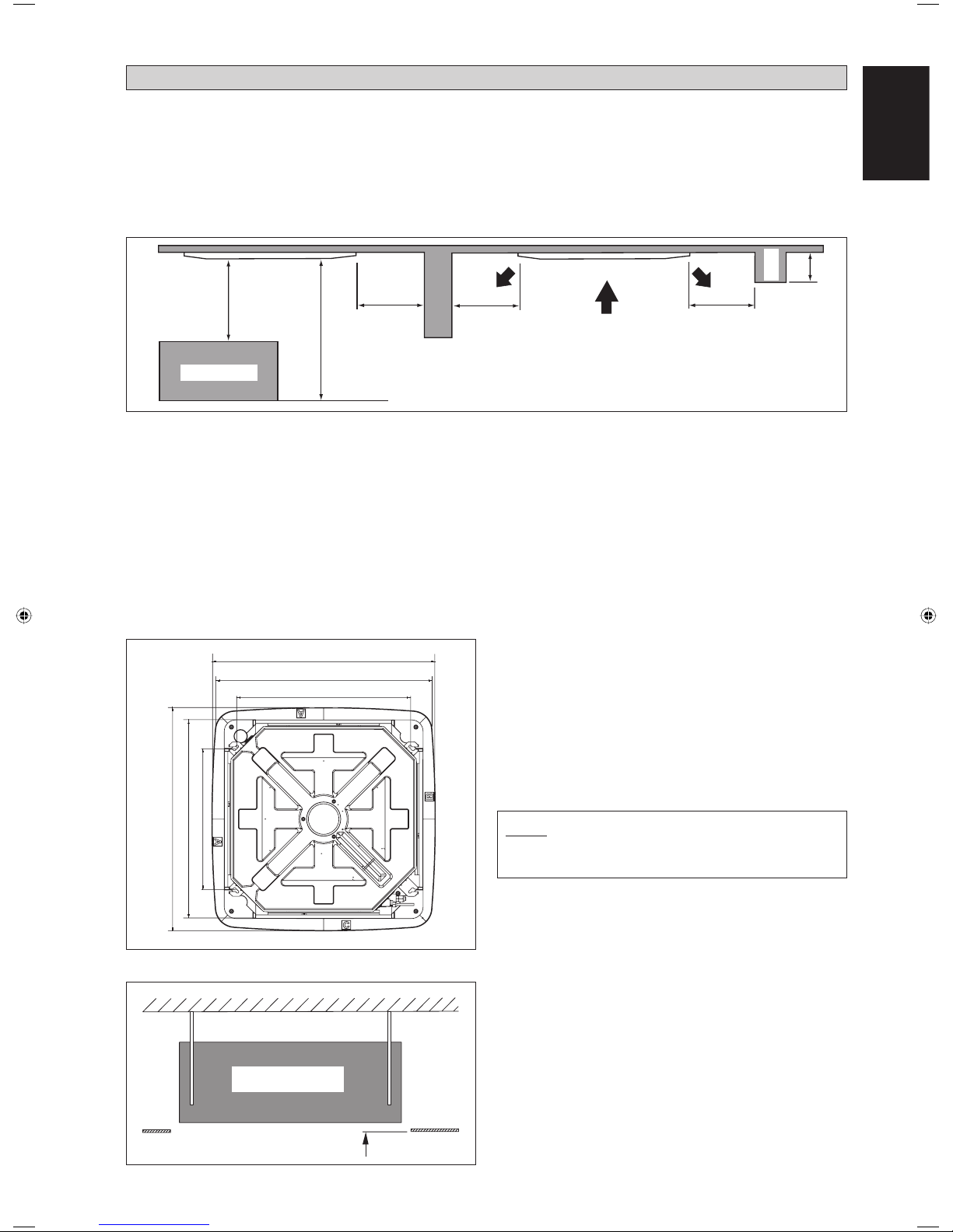
Obstacle
1m or more
3m or more
Floor
0.5m or more 0.5m or more 0.5m or more
0.3m or less
Beam
990.0mm
30 mm
Indoor Unit
Ceiling
Board
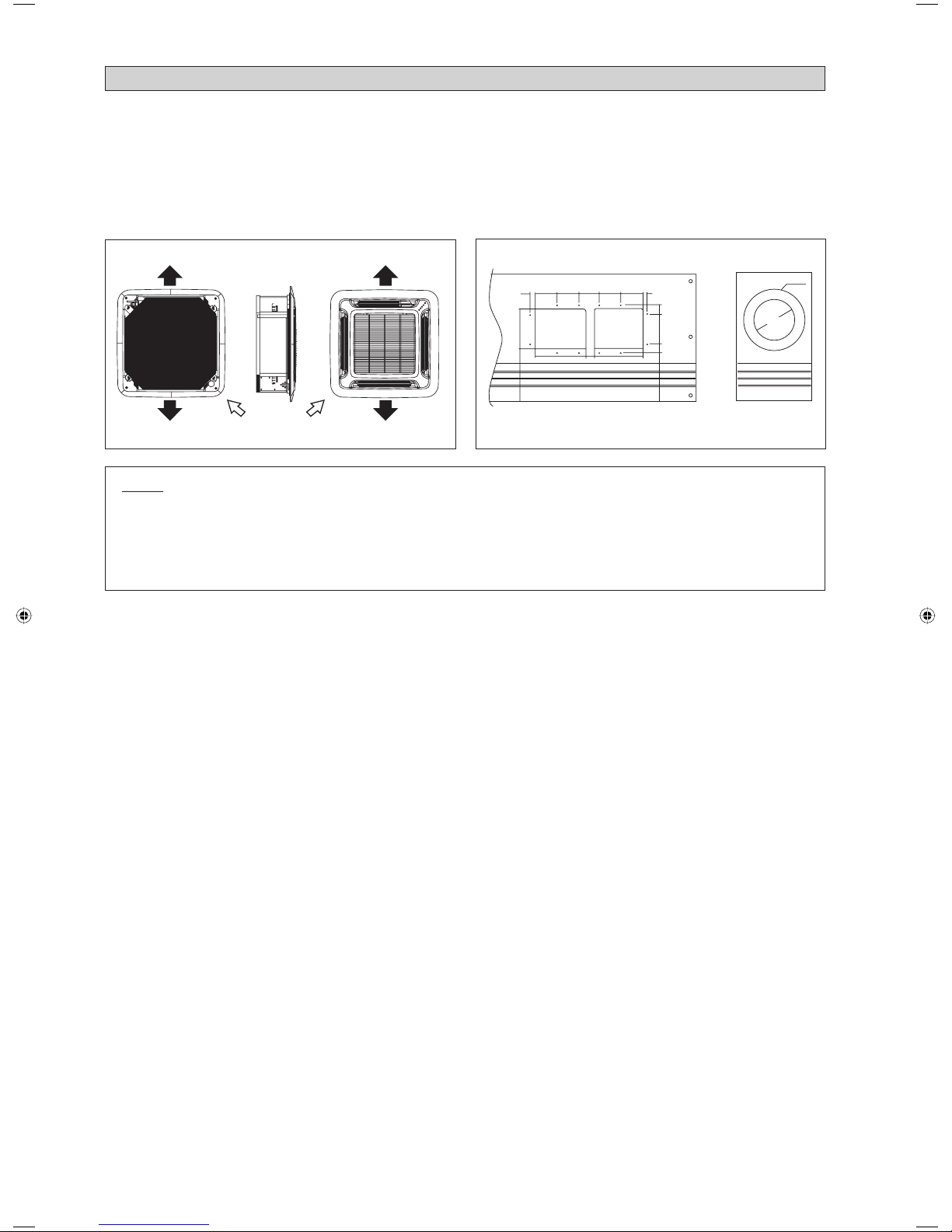
NOTE
Be sure to discuss the ceiling drilling work with the installers
concerned.
• Measure and mark the position for the hanging rod. Drill
the hole for the angle nut on the ceiling and fi x the hanging
rod.
• The installation template is extended according to
temperature and humidity. Check on dimensions in use.
• The dimensions of the installation template are the same as
those of the ceiling opening dimensions.
• Before ceiling laminating work is completed, be sure to fi t
the installation template to the indoor unit.
• Confi rm the pitch of the hanging rod is 770mm 622mm
sharp.
• Hold the unit and hang it on the hanging rod with the nut
and washer.
• Adjust the unit height to 30 mm between the indoor unit
bottom surface and the ceiling surface.
• Confirm with a level gauge that the unit is installed
horizontally and tighten the nut and bolt to prevent unit
falling and vibration.
• Open the ceiling board along the outer edge of the paper
installation template.
Unit Hanging
Unit Installation
INSTALLATION OF THE INDOOR UNIT
Preliminary Site Survey
Be sure to read this manual before installing the air-conditioner indoor unit.
• Voltage supply fl uctuation must not exceed ±10% of rated voltage. Electricity supply lines must be independent of welding
transformers which can cause high supply fl uctuation.
• Ensure that the location is convenient for wiring, piping and drainage.
• Do not exert pressure on the resin parts when opening the unit or when moving it after opening.
• Do not move the unit from packaging while moving, until it reaches the installation site. Use safe material or protection
plates when unpacking it or lifting it to avoid damage or scratches to the unit.
880.0~990.0mm (Ceiling Opening Site = 890mm)
770.0mm (Hanging Rod)
880.0~990.0mm (Ceiling Opening Site)
Piping Direction
622.0mm (Hanging Rod)
• Ensure a location where:
a) Drainage can be done easily.
b) Convenient for wiring and piping.
c) Which have enough space for installation and service work.
d) Where no risk of fl ammable gas leakage.
e) When free from any obstacles in path of cool air discharge and warm air return and must allow spreading of air throughout
the room (near the center of the room).
f) Must be provided clearance for indoor unit from the wall and obstacles as shown in fi gure below.
g) The installation place must be strong enough to support a load 4 times the indoor unit weight to avoid amplifying noise
and vibration.
h) The installation place (hanging ceiling surface) must be assuring levelness and the height in the ceiling is 350mm or
more.
i) The indoor unit must be away from heat and steam sources (avoid installing it near an entrance).
990.0mm
Page 10
1-8
Open
Screw
From
Unit
Control
Box
From
Front
Panel
LED Wire
Air Swing Wire
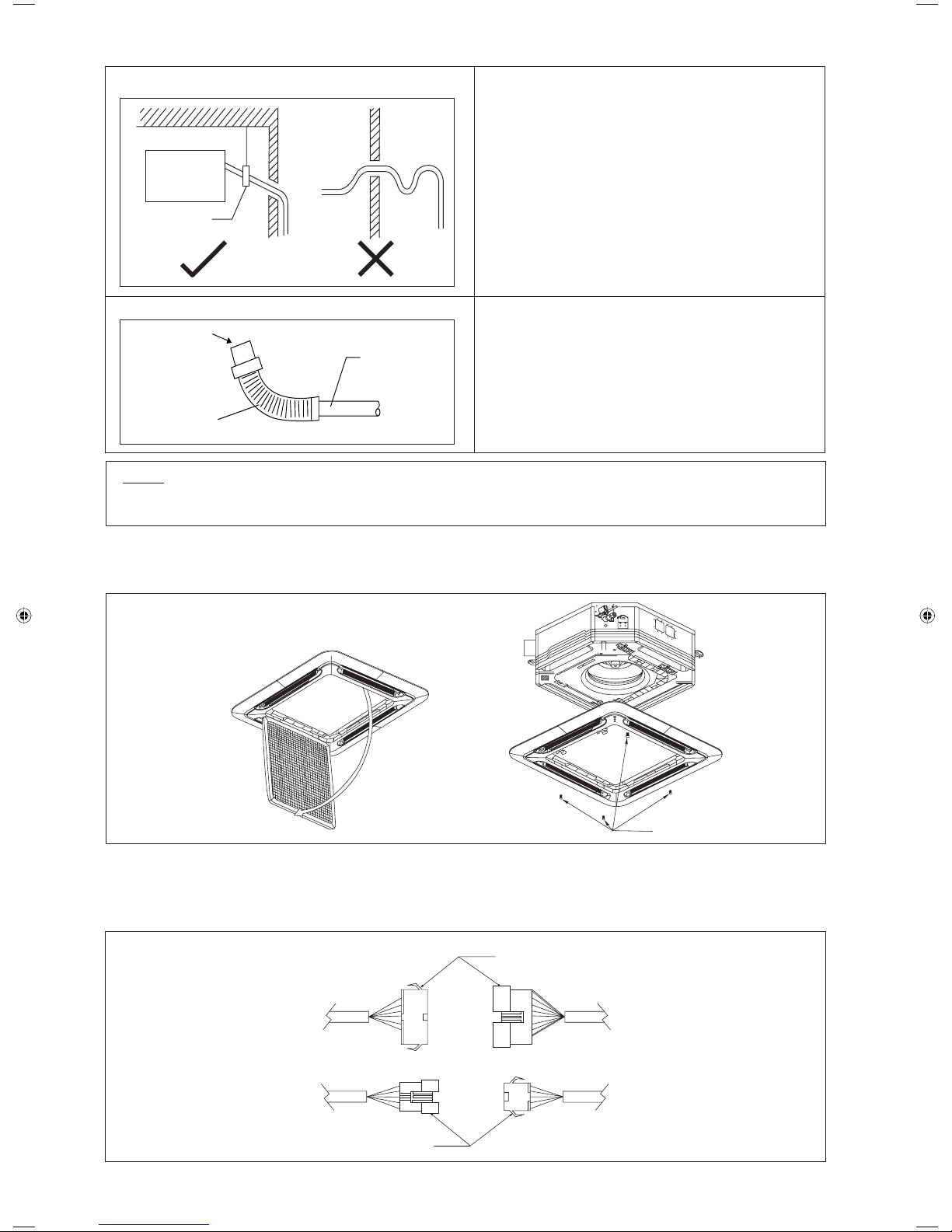
•
The front panel can only be fi tted in one direction, follow the piping direction. (Follow piping arrow sticker on front panel)
• Be sure to remove the installation template before installing the front panel.
Panel Installation
• Open the air intake grille by pulling back the catchers and removing it together with fi lter from panel.
• Install the front frame panel onto the indoor unit by 4 screws and tighten it completely to prevent cool air leakage.
• Connect the LED wire and air swing wire to the indoor unit.
• The air swing connector must put inside the control box after connected.
NOTE
This Indoor Unit uses a drain pump for condensed water drainage. Install the unit horizontally to prevent water leakage
or condensation around the air outlet.
Indoor Unit
Pipe Clamp
Feed Water
Flexible Drain Hose
Main Drain Pipe
•
Drain pipe must be in downward gradient for smooth
drainage.
•
Avoid installing the drain pipe in up and down slope to
prevent reversed water fl ow.
•
During the drain pipe connection, be careful not to exert
extra force on the drain connector at indoor unit.
•
The outside diameter of the drain connection at the
fl exible drain hose is 20 mm.
•
Be sure to execute heat insulation (polyethylene foam
with thickness more than 8.0 mm) on the drain piping to
avoid the condensed water dripping inside the room.
• Connect the main drain pipe to the fl exible drain.
• Feed water from fl exible drain hose to check the piping
for leakage.
• When the test is completed, connect the fl exible drain
hose to the drain connector on the indoor unit.
Drain Pump Work
Drain Test
Page 11
1-9
English
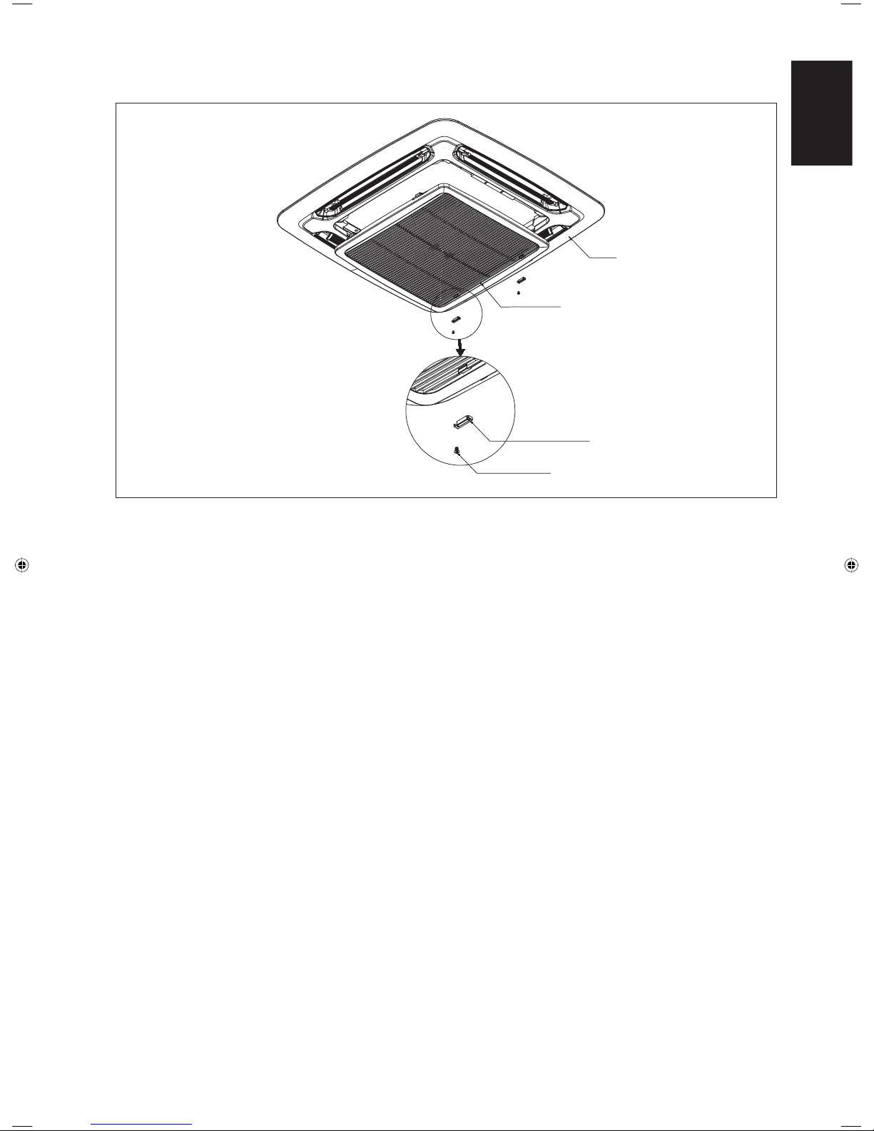
Frame
Intake Grille
Cover Lock Grille
(2pcs)
Screw M4 x 6
(2pcs)
Cover Lock Grille (The moving part protection for user direct touching)
Cover lock grill must be installed as the fi gure below.
If the unit need to be service, steps below shall be followed:
1. Confi rm that the unit had been switched off before servicing the unit.
2. Use screwdriver to unlock the screw on the cover lock grille.
3. Remove the cover lock grille and open the intake grille for the service purpose.
4. Install the intake grille and screw the cover lock grille after service and make sure the unit is proper install.
Page 12

1-10
Figure 2 Figure 3
Figure 4 Figure 5
Wires Installation
Figure 1 and Figure 2 shows the location of cover wire in CKE unit.
Steps to install power supply wires and wires from outdoor unit.
1. Remove wire cover by removing 2 screws as shown in Figure 3.
2. Wires will go through the hole as shown in Figure 4 and 5 respectively without crossing the height of the hole.
3. After that, wire cover will be assembled back to close the wire.
Figure 1
! CAUTION
Do not install the unit at altitude over 2000m for both indoor and outdoor.
Page 13
1-11
English
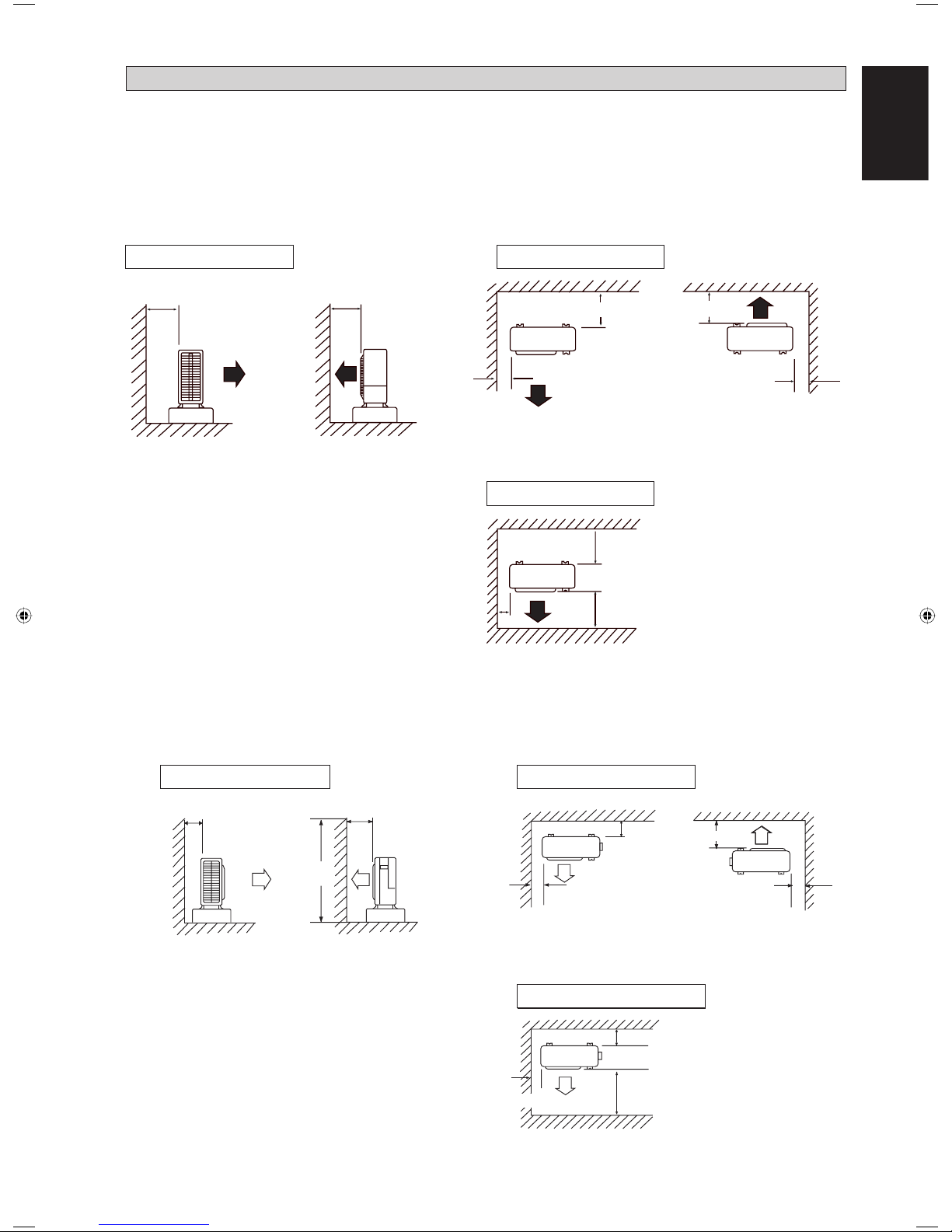
• The outdoor unit must be installed in such a way, so as to prevent short circuit of the hot discharged air or obstruction to
the smooth air fl ow. Please follow the installation clearance shown in the fi gures below. Select the coolest possible place
where intake air temperature is not greater than the outside air temperature.
• Where a wall or other obstacles is in the path of outdoor unitʼs intake or exhaust airfl ow, follow the installation guidelines
below.
• For any of the below installation patterns, the wall height on the exhaust side should be 1200mm or less.
5SLY20/25C/CR
More than 50 More than 100
Side View
Top View
Top View
More than 50
More than 50
More than 50
More than 150
More than 100
More than 150
More than 300
Unit: mm
INSTALLATION OF THE OUTDOOR UNIT
Wall facing one side
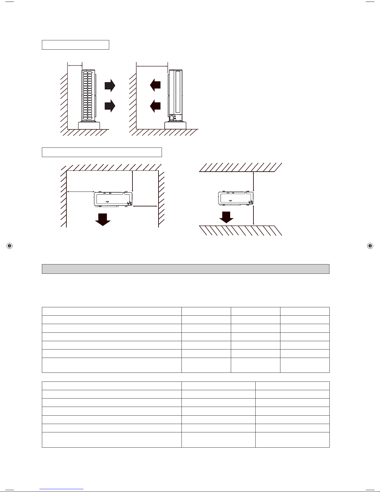
More than 100 More than 350
More than 50
More than 50
Top View
Top View
Side View
More
than 100
More than 350
More than 100
More than 350
Unit: mm
5SLY28CR
1200
or less
More than 50
Wall facing two sides
Wall facing two sides
Wall facing one side Wall facing two sides
Wall facing three sides
Page 14
1-12
5SLY40/50FR
More than 100 More than 500
More
than 100
More
than
100
More than 100
More than 100
More than 500
• Allow more space for installation above with additional obstacle at top side and installation in series.
Top View
Side View
Unit: mm
REFRIGERANT PIPING
Indoor 5CKY20E/ER 5CKY25E/ER 5CKY28ER
Outdoor 5SLY20C/CR 5SLY25C/CR 5SLY28CR
Max. allowable length, m 30 30 50
Max. allowable elevation, m 10 10 30
Liquid pipe size, mm/(in) 6.35 (1/4") 6.35 (1/4") 9.52 (3/8")
Gas pipe size, mm/(in) 12.70 (1/2") 15.88 (5/8") 15.88 (5/8")
Additional charge of refrigerant, g/m
(for piping length above 7.5m)
20 20 50
Indoor 5CKY40ER 5CKY50ER
Outdoor 5SLY40FR 5SLY50FR
Max. allowable length, m 75 75
Max. allowable elevation, m 30 30
Liquid pipe size, mm/(in) 9.52 (3/8") 9.52 (3/8")
Gas pipe size, mm/(in) 15.88 (5/8") 15.88 (5/8")
Additional charge of refrigerant, g/m
(for piping length above 30m)
50 50
Allowable Piping Length
When the pipe length becomes too long, both the capacity and reliability drop. As a result, compressor reliability will be
affected. Always choose the shortest path and follow the recommendation as tabulated below:
Wall facing one side
Wall facing more than 1 side of obstacle
Page 15
1-13
English
D
A
Piping Works And Flaring Technique
• Do not use contaminated or damaged copper tubing. If any pipings, evaporator or condenser had been exposed or had been
opened for 15 seconds or more, the system must be vacuumed. Generally, do not remove plastic, rubber plugs and brass
nuts from the valves, fi ttings, tubings and coils until it is ready to connect suction or liquid line into valves or fi ttings.
• If any brazing work is required, ensure that the nitrogen gas is passed through coil and joints while the brazing work is
being done. This will eliminate soot formation on the inside walls of the copper tubings.
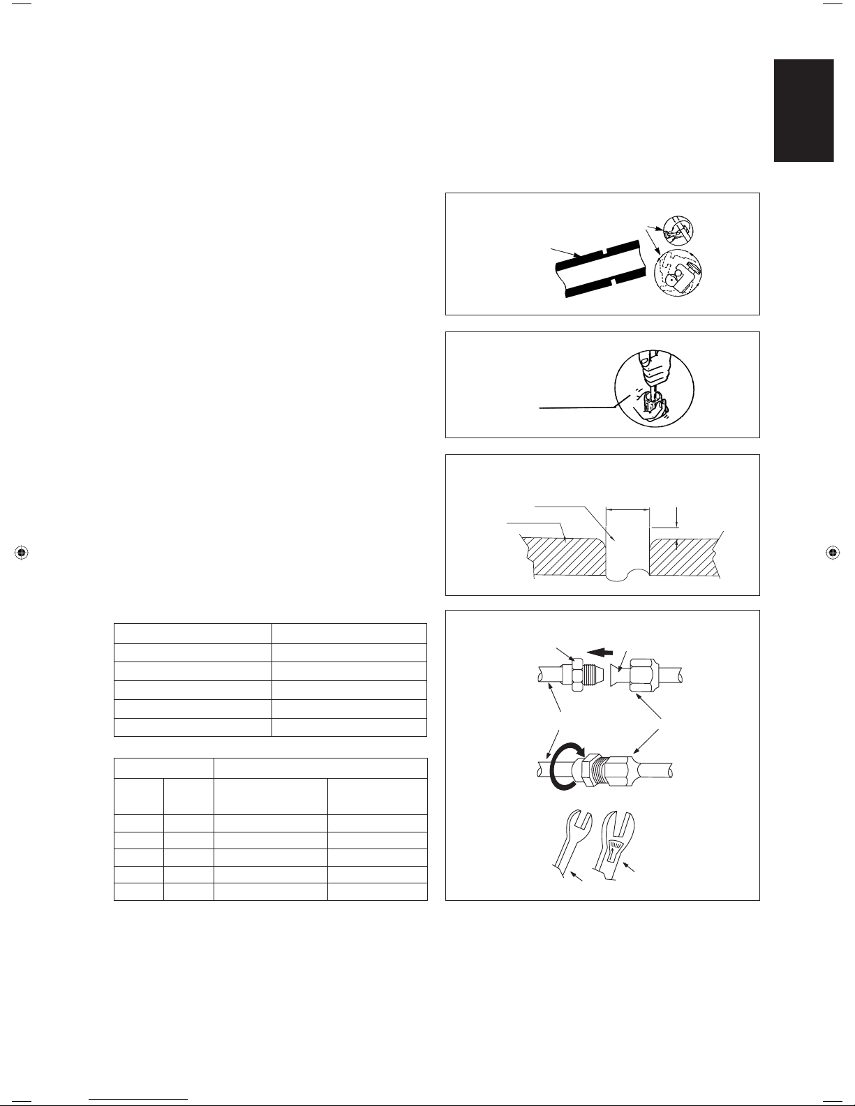
• Cut the pipe stage by stage, advancing the blade of the pipe cutter slowly. Extra force and deep cut will cause more distortion
on the pipe and thus extra burr. See Figure A.
Cutting Copper Tube
Fig. B
Fig. A
Remove Burr
Fig. C
Copper Tube
Swaging Block
• Remove burrs from cut edges of the pipes with remover
as shown in Figure B. This will avoid unevenness on the
fl are faces which will cause gas leak. Hold the pipe on
top position and burr remover at lower position to prevent
metal chips from entering the pipe.
• Insert the fl are nuts, mounted on the connection parts of
both the indoor unit and outdoor unit, into the copper
pipes.
• The exact length of pipe protruding from the top surface of
the swaging block is determined by the fl aring tool. Refer
Figure C.
• Fix the pipe fi rmly on the swaging block. Match the centers
of both the fl are die and the fl aring punch, and then tighten
the fl aring punch fully.
Piping Connection To The Units
• Align the center of the piping and tighten the fl are nut
suffi ciently with fi ngers. Refer Figure D.
• Finally, tighten the fl are nut with the torque wrench until
the wrench clicks.
• When tightening the fl are nut with the torque wrench,
ensure that the tightening direction follows the arrow
indicated on the wrench.
• The refrigerant pipe connection are insulated by closed
cell polyurethane.
Spanar
Torque Wrench
Indoor Piping
Flare Nut
Flared Tube
Flare Joint
Fig. D
Ø Tube, D A (mm)
Inch mm Imperial
(Wing-nut Type)
Rigid
(Clutch Type)
1/4" 6.35 1.3 0.7
3/8" 9.52 1.6 1.0
1/2" 12.70 1.9 1.3
5/8" 15.88 2.2 1.7
3/4" 19.05 2.5 2.0
Pipe Size (mm/in) Torque (Nm/ft-lb)
6.35 (1/4) 18 (13.3)
9.52 (3/8) 42 (31.0)
12.70 (1/2) 55 (40.6)
15.88 (5/8) 65 (48.0)
19.05 (3/4) 78 (57.6)
1/4t
Page 16
1-14
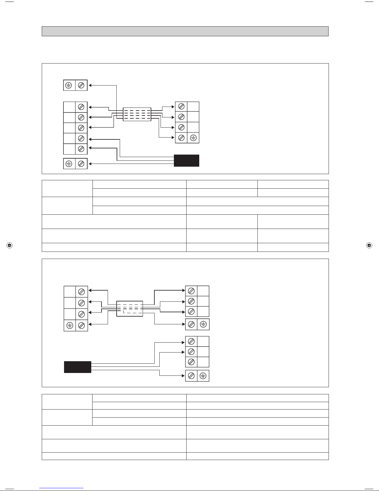
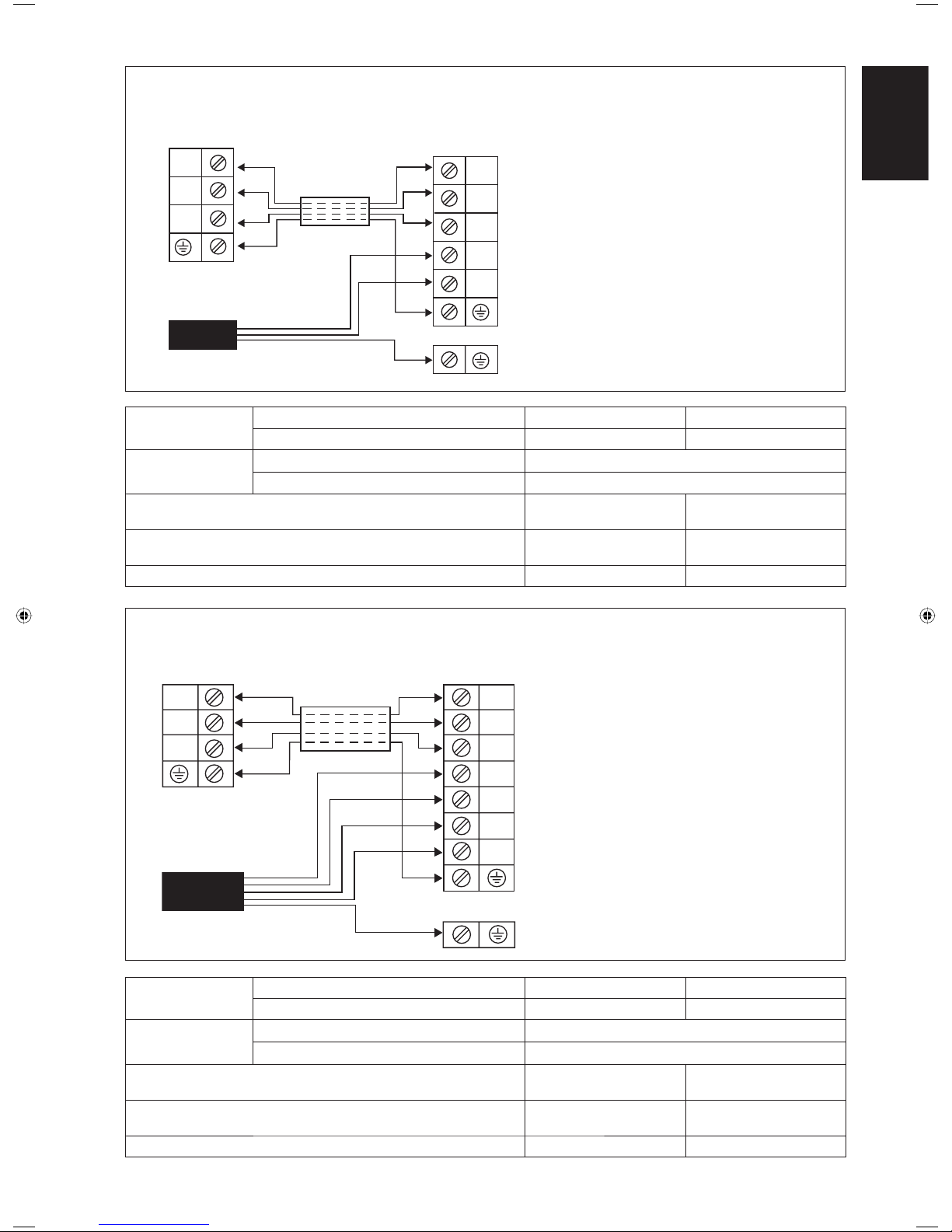
Power Supply Cable
Outdoor Unit
Terminal Block
Indoor Unit
Terminal Block
L
N
SIG
2
1
SIG
2
1
5CKY20/25E/ER - 5SLY20/25C/CR
IMPORTANT: *
These values are for information only, they should be checked and selected to comply with the local and/or national
codes and regulations. They are also subjected to the type of installation and size of conductors used.
**
The appropriate voltage range should be checked with the label data on the unit.
Interconnection
Cable
ELECTRICAL CONNECTION
Model Indoor 5CKY20E/ER 5CKY25E/ER
Outdoor 5SLY20C/CR 5SLY25C/CR
Voltage range** Indoor
220V - 240V /1Ph /50Hz + !
Outdoor
220V - 240V /1Ph /50Hz + !
Power supply cable size* mm
2
Number of conductors
2.5
3
2.5
3
Interconnection cable size* mm
2
Number of conductors
2.5
4
2.5
4
Recommended time delay fuse* A 20 20
5CKY28ER - 5SLY28CR
Indoor Unit
Terminal Block
L
Interconnection
Cable
Model Indoor 5CKY28ER
Outdoor 5SLY28CR
Voltage range** Indoor
220V - 240V/1Ph/50Hz + !
Outdoor
220V - 240V/1Ph/50Hz + !
Power supply cable size* mm
2
Number of conductors
2.5
3
Interconnection cable size* mm
2
Number of conductors
1.5
4
Recommended time delay fuse* A 25
Power Supply Cable
There must be an all pole
disconnection in the supply
mains with a contact separation
of at least 3mm.
!
There must be an all pole
disconnection in the supply
mains with a contact separation
of at least 3mm.
!
Outdoor Unit
Terminal Block
N
SIG
SIG
N
L
N
L
Page 17
1-15
English
3
2
1
3
2
1
L1
L2
L3
N
Power Supply Cable
Outdoor Unit
Terminal Block
Indoor Unit
Terminal Block
5CKY40ER - 5SLY40FR (1 Phase)
5CKY50ER - 5SLY50FR (1 Phase)
3
2
1
2
1
3
L
N
Interconnection
Cable
Model Indoor 5CKY40ER 5CKY50ER
Outdoor 5SLY40FR 5SLY50FR
Voltage range** Indoor
220V - 240V/1Ph/50Hz + !
Outdoor
220V - 240V/1Ph/50Hz + !
Power supply cable size* mm
2
Number of conductors
6
3
6
3
Interconnection cable size* mm
2
Number of conductors
1.5
4
1.5
4
Recommended time delay fuse* A 32 32
5CKY40ER - 5SLY40FR (3 Phase)
5CKY50ER - 5SLY50FR (3 Phase)
There must be an all pole
disconnection in the supply
mains with a contact separation
of at least 3mm.
!
Model Indoor 5CKY40ER 5CKY50ER
Outdoor 5SLY40FR 5SLY50FR
Voltage range** Indoor
220V - 240V/1Ph/50Hz + !
Outdoor
380V - 415V/3N~/50Hz + !
Power supply cable size* mm
2
Number of conductors
4
5
4
5
Interconnection cable size* mm
2
Number of conductors
1.5
4
1.5
4
Recommended time delay fuse* A 20 20
Power Supply Cable
Indoor Unit
Terminal Block
Interconnection
Cable
Outdoor Unit
Terminal Block
There must be an all pole
disconnection in the supply
mains with a contact separation
of at least 3mm.
!
Page 18
1-16
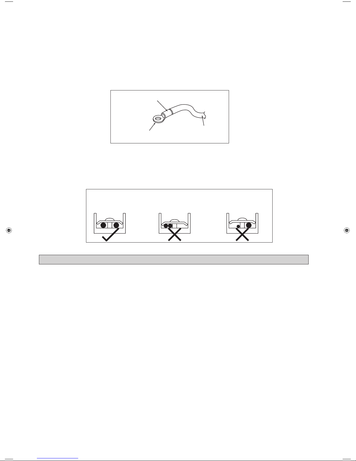
Attach insulation sleeve
Round crimp-style terminal
Electric wire
Connect wires of the
same gauge to both side.
Do not connect wires of the
same gauge to one side.
Do not connect wires
of different gauges.
• All wires must be fi rmly connected.
• Make sure all the wire do not touch the refrigerant pipings, compressor or any moving parts.
• The connecting wire between the indoor unit and the outdoor unit must be clamped by using provided cord anchorage.
• The power supply cord must be equivalent to H07RN-F which is the minimum requirement.
• Make sure no external pressure is applied to the terminal connectors and wires.
• Make sure all the covers are properly fi xed to avoid any gap.
• Use round crimp-style terminal for connecting wires to the power supply terminal block. Connect the wires by matching
to the indication on terminal block. (Refer to the wiring diagram attached on the unit).
• Use the correct screwdriver for terminal screws tightening. Unsuitable screwdrivers can damage the screw head.
• Over tightening can damage the terminal screw.
• Do not connect wire of different gauge to same terminal.
• Keep wiring in an orderly manner. Prevent the wiring from obstructing other parts and the terminal box cover.
R410A is a new HFC refrigerant which does not damage the
ozone layer. The working pressure of this new refrigerant is 1.6
times higher than conventional refrigerant (R22), thus proper
installation / servicing is essential.
• Never use refrigerant other than R410A in an air conditioner
which designed to operate with R410A.
• POE or PVE oil is used as lubricant for R410A
compressor, which is different from the mineral oil used
for R22 compressor. During installation or servicing, extra
precaution must be taken not to expose the R410A system
too long to moist air. Residual POE or PVE oil in the piping
and components can absorb moisture from the air.
• To prevent mischarging, the diameter of the service port
on the fl are valve is different from that of R22.
• Use tools and materials exclusively for refrigerant R410A.
Tools exclusively for R410A are manifold valve, charging
hose, pressure gauge, gas leak detector, fl are tools, torque
wrench, vacuum pump and refrigerant cylinder.
• As an R410A air conditioner incurs higher pressure
than R22 units, it is essential to choose the copper pipes
correctly. Never use copper pipes thinner than 0.8mm even
though they are available in the market.
• If the refrigerant gas leakage occurs during installation /
servicing, be sure to ventilate fully. If the refrigerant gas
comes into contact with fi re, a poisonous gas may occur.
• When installing or removing an air conditioner, do not
allow air or moisture to remain in the refrigerant cycle.
SPECIAL PRECAUTIONS WHEN DEALING WITH R410A UNIT
Page 19
1-17
English
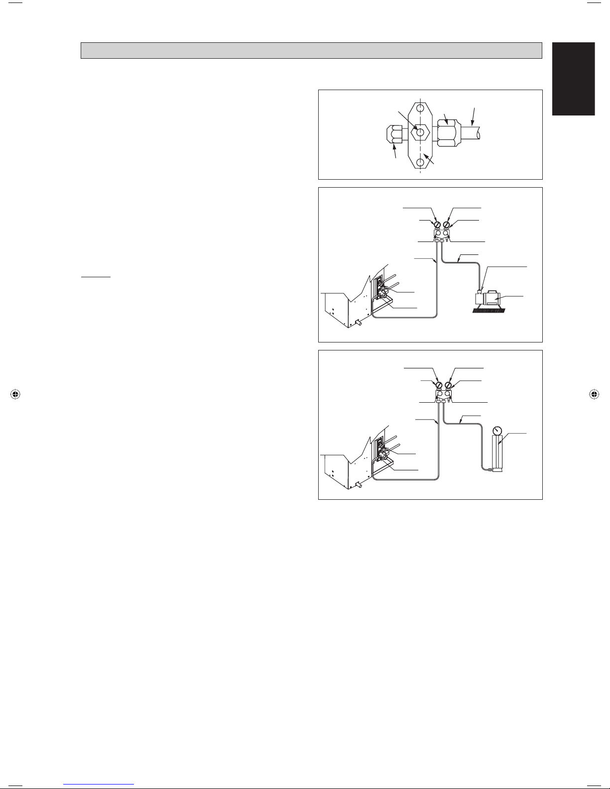
Vacuuming is necessary to eliminate all moisture and air from the system. The series II Outdoor Unit is provided with fl are
valve fi ttings.
Vacuuming The Piping And The Indoor Unit
Except for the outdoor unit which is pre-charged with
refrigerant, the indoor unit and the refrigerant connection
pipes must be air-purged because the air containing moisture
that remains in the refrigerant cycle may cause malfunction
of the compressor.
• Remove the caps from the valve and the service port.
• Connect the center of the charging gauge to the vacuum
pump.
• Connect the charging gauge to the service port of the 3-way
valve.
• Start the vacuum pump. Evacuate for approximately 30
minutes. The evacuation time varies with different vacuum
pump capacity. Confi rm that the charging gauge needle has
moved towards -760mmHg.
Caution
• If the gauge needle does not move to -760mmHg, be sure to
check for gas leaks (using the refrigerant detector) at fl are
type connection of the indoor and outdoor unit and repair
the leak before proceeding to the next step.
• Close the valve of the changing gauge and stop the vacuum
pump.
• On the outdoor unit, open the suction valve (3 way) and
liquid valve (2 way) (in anti-clockwise direction) with 4mm
key for hexagon sacked screw.
Charge Operation
This operation must be done by using a gas cylinder and a
precise weighing machine. The additional charge is topped-up
into the outdoor unit using the suction valve via the service
port.
• Remove the service port cap.
• Connect the low pressure side of the charging gauge to the
suction service port center of the cylinder tank and close
the high pressure side of the gauge. Purge the air from the
service hose.
• Start the air conditioner unit.
• Open the gas cylinder and low pressure charging valve.
• When the required refrigerant quantity is pumped into
the unit, close the low pressure side and the gas cylinder
valve.
• Disconnect the service hose from service port. Put back the
service port cap.
VACUUMING AND CHARGING
Refrigerant Piping
Outdoor Unit 3 ways valve
Allen key
Service Port
Flare nut
HIGH PRESSURE GAUGE
GAUGE MANIFOLD
LOW PRESSURE GAUGE
HANDLE HI (ALWAYS CLOSED)
CHARGE HOSE
-760mmHg
HANDLE LO
CHARGE HOSE
VACUUM PUMP
ADAPTER FOR
COUNTER FLOW
PREVENTION
CHECK VALVE
LIQUID VALVE
HIGH PRESSURE GAUGE
LOW PRESSURE GAUGE
GAUGE MANIFOLD
-760mmHg
HANDLE LO
HANDLE HI (ALWAYS CLOSED)
CHARGE HOSE
CHARGE HOSE
CHECK VALVE
LIQUID VALVE
GAS VALVE
(3-WAY)
CONFIGURATION OF AIR
PURGE BY CHARGING
CONFIGURATION OF AIR
PURGE BY CHARGING
GAS VALVE
(3-WAY)
Page 20
1-18
Sealing Material
• It is possible to seal one of the four air discharge outlet. (sealing two or more air discharge outlet could cause a
malfunction)
• Remove the front panel and insert the sealing material into the air discharge outlet on the indoor unit to seal the air
outlet.
• The sealing material is the same length as the longer air discharge outlet. If it is desired to seal the shorter air discharge
outlet, cut the sealing material to shorten it.
• Push the sealing material in about 10 mm beyond the bottom surface of the indoor unit so that it does not touch the air
louver. Be sure not to push the sealing material in any farther than about 10mm.
Short Duct Specifi cation
• The indoor unit is provided with air discharge and air intake “knock-out” hole for duct connection. However the connection
of the short duct for air discharge is possible on only one side.
• The use of short duct for air discharge will improve airfl ow distribution if there is an obstruction (such as a lighting fi xture)
or in a long, narrow room or an L-shaped room. It also use for air conditioning of two rooms simultaneously.
Possible Opening Dimension For Duct Connection
Air Discharge Knock Out Hole
Air Intake Knock
Out Hole
Possible Direction For Air Discharge And Air Intake
Air Intake
Air DischargeAir Discharge
Air Discharge Air Discharge
10
50 50 50 50 50 10
207020
90
Ø100
PCD Ø140
115 20 115
ACCESSORY PARTS
NOTE
• Avoid using the short duct on which the air discharge grille can be completely closed, to prevent evaporator
freezing.
• In order to prevent condensation forming, be sure that there is suffi cient thermal insulation and no leakage of cool
air when installing the short duct.
• Keep the introduction of fresh air intake within 20% of total air fl ow. Also provide chamber and use booster fan.
Page 21
1-19
English
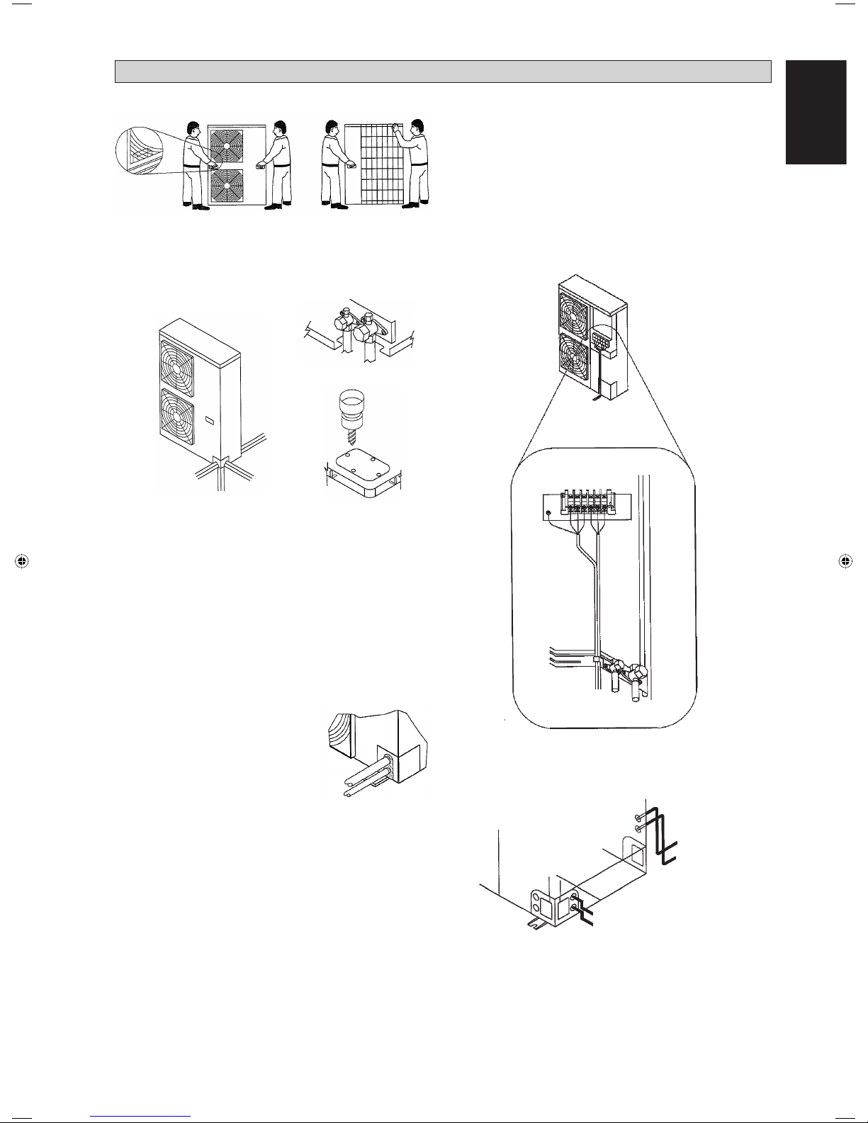
As shown in Figure above, it is recommended to move the
unit by grabbing the left and right grip. Place your hands on
the corner to avoid deforming of the casing.
Figure 1
A total of 4 direction options (refer fi gure 2a) for connecting
pipe (w, x, y, z) are available for your convenience.
Cutting out the 2 slits with a metal saw make it possible to
install as shown in Figures 2a.
In order to make the connecting pipe in a downward direction
(refer Figure 2b), make a knockout hole by drilling through
the center area around the knockout hole.
It is recommended to use a Ø6mm drill for this process
(refer Figure 2c).
After completing the knockout process, it is recommended
to apply repair paint to the edge and surrounding surfaces to
prevent rusting.
Z
Y
X
W
Figure 2a
Figure 2b
Figure 2c
1. Handling
2. Refrigerant piping
Cover the pipe through-holes with
insulation material to conceal all gaps
to prevent small animals or insects from
entering the outdoor unit which may
result short circuit in the control box.
Figure 3
3. Caution for handling service port
To be able to recover all remaining refrigerant at charge
hose, always use a fl exible charge hose with a push-rod and
valve. After the work, tighten the valve cover in place with
tightening torque: 11.5~13.9N.m
4. Charging refrigerant
For cases where complete recharge of refrigerant is required,
vacuuming via service part is mandatory, do not use stop valve
port in this case because vacuuming through this stop valve
port can not be executed completely.
Outdoor units have 1 port on the piping. It is between the heat
exchanger and the 4-way valve.
5. Pump-down operation
Never by-pass the low pressure switch or low pressure sensor
during pump down operation.
Power supply must be cut off before pump-down operation.
After opening the front panel, cover the PCB and terminal
board with insulation sheet to avoid electric shock by
accidental touching of LIVE parts.
Do not leave the unit unattended if the front panel is open.
Close the front panel before leaving the outdoor unit.
Turn on the power supply and carry out pumping-down
operation according to the steps written at front panel.
6. Electrical wiring work
BELOW INFORMATION IS APPLICABLE FOR 5SLY40/50FR ONLY
Figure 4
Secure the ground wire to the stop valve attachment plate
(refer Figure 4) so that it does not slide.
Ensure the front cover does not rise up after the wiring work
is down. Close the front cover securely.
1
2
1
2
Figure 5
When cables are routed from the unit, a protection sleeve for
the conduits can be inserted at the knock-out hole.
It there is no wire conduit, do protect the wires with
vinyl tubes to prevent cutting the wires by sharp edges of
knock-out hole.
1 Power supply wiring and earth wire
2 Interconnection wire
Page 22
1-20
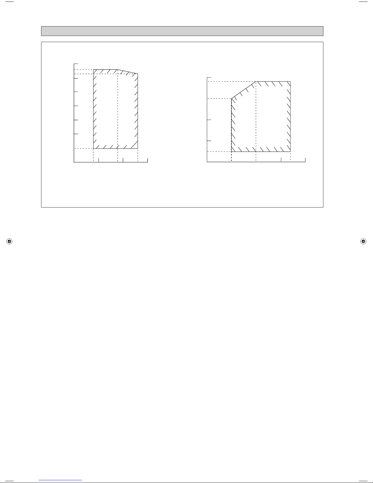
20
18
10
0
-10
-15
-20-20
10 15 20 25 27 30
50
46
43
40
20
30
10
0
-10
10 1415 19 20 23 25
COOLING HEATING
INDOOR TEMP. WB (˚C) INDOOR TEMP. DB (˚C)
DB: Dry bulb WB: Wet bulb
OUTDOOR TEMP. DB (˚C)
OUTDOOR TEMP. WB (˚C)
OPERATING RANGE
Page 23
1-21
English
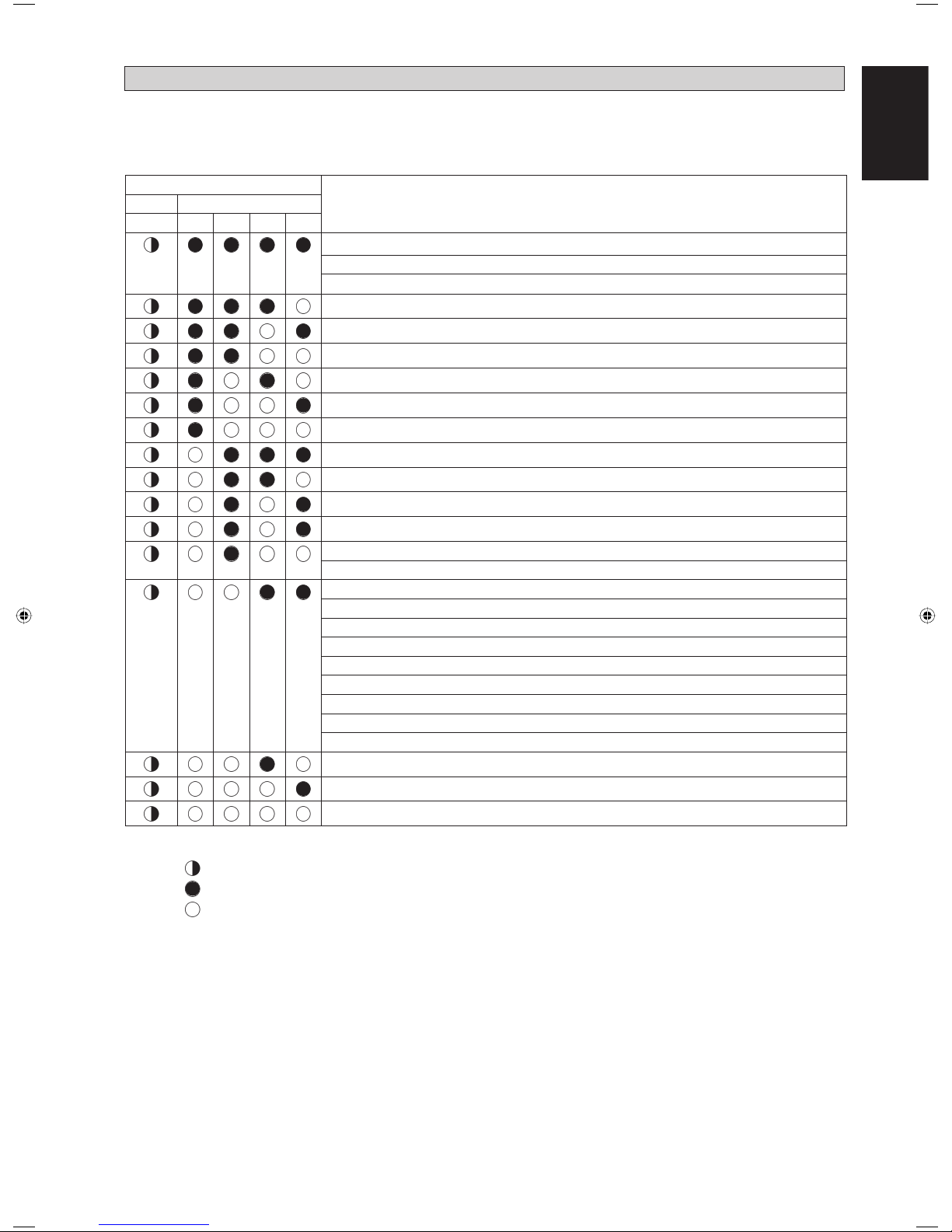
INDICATOR LIGHTS
Fault Diagnosis
LED INDICATION
DescriptionGreen Red
A1234
NORMAL
INSTALLATION ERROR
ANTIFREEZE (OTHER ROOMS)
HEAT SINK OVERHEAT
IPM ERROR/IGBT ERROR
INSUFFICIENT GAS
AC INPUT OVER CURRENT
COMPRESSOR START-UP ERROR
COMMUNICATION ERROR (OUTDOOR CONTROL PCB AND IPM PCB)
4 WAY VALVE ERROR
DC VOLTAGE OUT OF RANGE
COMPRESSOR MOTOR LOCK/COMPRESSOR OVERLOADED
DISCHARGE PIPE OVERHEAT
ANTIFREEZE (COOLING)/HEAT EXCHANGER OVERHEAT (HEATING)
HEAT EXCHANGER OVERHEAT
COMPRESSOR SENSOR SYSTEM ERROR
COMPRESSOR FEEDBACK DETECTION ERROR
AC CURRENT SENSOR ERROR
OUTDOOR AIR THERMISTOR SHORT/OPEN
COMPRESSOR DISCHARGE PIPE THERMISTOR SHORT/OPEN/MISPLACED
OUTDOOR HEAT EXCHANGER THERMISTOR SHORT/OPEN
LIQUID PIPE THERMISTOR SHORT/OPEN
GAS PIPE THERMISTOR SHORT/OPEN
HEAT SINK THERMISTOR SHORT/OPEN
OUTDOOR CONTROL BOX OVERHEAT
OUTDOOR PCB ERROR
OUTDOOR DC FAN MOTOR LOCK
The outdoor unit LED indicates the running condition of the system:
If faulty condition occurs, please contact the nearest local dealer or qualifi ed service personnel. Do not attempt to
troubleshoot the unit yourself. For any enquiries on spare parts please contact your authorized dealer.
Legend
Blinks
Off
On
5SLY28CR
Page 24

MEMO
Page 25
2-1
Français
Unité Intérieure 5CKY20/25E/ER & 5CKY28/40/50ER
A
B
C
D
E
F
H
K
J
I
G
Traduction des instructions dʼorigine
Toutes les dimensions sont données en mm
CONTOUR ET DIMENSIONS
Dimension
Modèle
ABCDE FGH I JK
5CKY20/25E/ER
5CKY28ER
820 820 340 300 40 990 990 627 627 607 430
5CKY40/50ER 820 820 375 335 40 990 990 627 627 607 430
Unité Extérieure 5SLY20/25C/CR
N
L
KL
TN
M
A
D
O
PBQ
RS
C
HG
FE
IJ
Dimension
Modèle
ABCDE FGH I JKLMNOPQRST
5SLY20/25C/CR
855 730 328 513 182 44 93 149 101 113 603 126 164 15 47 3 23 73 75 362
Toutes les dimensions sont données en mm
Page 26
2-2
Unité Extérieure 5SLY28CR
A
D
K
E
S
T
S
T
GRR
OMN
H
P
Q
L
C
FU
J
B
I
Dimension
Modèle
ABCDE FGH I JKLMNOPQRSTU
5SLY28CR
940 348 753 855 392 733 603 328 303 370 362 448 190 80 58 180 32 126 32 15 23
Page 27

2-3
Français
Unité Extérieure 5SLY40/50FR
AB AC AD
AE
AFAG
AH
AI
AA
AJ
AK
A
C
B
D
F
E
L
M
KJ
NO
Q
P
R
S
T
U
V
W
Z
X
Y
AT
AS
H
G
AU
AP
AQ
AO
AL
AM
AN
Dimension
Modèle
ABCDE FGH I JKLMN
5SLY40/50FR
900 1374 30 24 60 89 142 89 19 54 95 423 430 95
OPQRSTUVWXYZ
54 19 89 145 84 55 55 223 148 13 52 67
AA AB AC AD AE AF AG AH AI AJ AK AL AM AN
350 140 620 140 30 320 30 59 43 40 94 117 102 70
AO AP AQ AR AS AT AU
45 376 191 70 58 16 16
Toutes les dimensions sont données en mm
AR
I
Page 28
2-4
PRÉCAUTIONS DE SÉCURITÉ
! ATTENTION ! AVERTISSEMENT
•
Lʼinstallation et la maintenance doivent être exécutées par une personne
qualifi ée qui est familiarisée avec les lois et réglementations en vigueur,
et aussi expérimentée dans ce type dʼéquipements.
•
Tous les câblages doivent répondre aux réglementations électriques
nationales.
•
Avant de commencer le raccordement suivant le schéma électrique,
sʼassurer que la tension nominale de lʼappareil corresponde bien à celle
indiquée sur la plaque signalétique.
•
Lʼunité doit être raccordée à la TERRE pour prévenir tous les risques
possibles dûes à un défaut dʼisolation.
•
Aucun câble électrique ne doit toucher la tuyauterie du réfrigérant, le
compresseur ou les pièces mobiles des moteurs de ventilation.
•
Avant lʼinstallation ou lʼentretien du climatiseur, sʼassurer que lʼappareil
est éteint (OFF).
•
Débrancher lʼappareil du circuit dʼalimentation secteur avant de procéder
à lʼentretien du climatiseur.
•
NE PAS retirer le câble dʼalimentation électrique de la prise quand
lʼappareil est sous branché. Il peut en résulter des décharges électriques
importantes susceptibles de provoquer un incendie.
•
Les unités intérieures et extérieures, le cordon dʼalimentation et le
câblage de transmission doivent rester à une distance dʼau moins 1m
des téléviseurs et des radios, ce afi n dʼéviter les images déformées et
les parasites. {En fonction du type et de la source des ondes électriques,
des parasites peuvent être entendus même avec une distance supérieure
à 1m}.
Vérifi er les points suivants au cours de lʼinstallation.
•
Ne pas installer lʼappareil où il peut se produire des fuites de gaz
infl ammable.
En cas de fuite et accumulation de gaz autour de lʼappareil, il y a
risque dʼincendie.
•
Sʼassurer que le tuyau dʼévacuation du condensat est correctement
branché.
Si le tuyau dʼévacuation nʼest pas correctement branché, les
éventuelles fuites dʼeau risquent de mouiller le mobilier.
•
Ne pas surcharger lʼunité (en fl uide frigorigène).
Cet appareil est préchargé en usine.
Une charge trop importante risque de provoquer une surcharge
électrique ou dʼendommager le compresseur.
•
Sʼassurer que le panneau supérieur de lʼappareil est remis en place
après lʼinstallation ou lʼentretien.
Avec un panneau mal fixé lʼ appareil va fonctionner
bruyamment.
•
Les bords coupants et les surfaces du refroidisseur tuulaire présentent
un risque de blessure.
Mieux vaut éviter le contact avec ces endroits.
•
Avant de couper lʼalimentation électrique, veiller à ce que
lʼinterrupteur ON/OFF de la télécommande soit en position
« OFF » afi n dʼéviter une mise en marche intempestive de lʼappareil.
Si lʼinterrupteur de la télécommande nʼest pas en position « OFF », les
ventilateurs de lʼappareil se mettront en marche dès que lʼalimentation
électrique est rétablie. Il peut en résulter un danger pour le personnel
dʼentretien ou lʼutilisateur.
•
Ne pas utiliser dʼappareil de chauffage trop près du climatiseur. Une
chaleur excessive peut déformer ou faire fondre le boîtier de plastic.
• Ne pas installer les appareils à proximité ou près dʼun passage de porte.
•
Ne pas utiliser un appareil de chauffage trop près dʼune unité de
climatisation ou lʼutiliser dans une pièce où, de lʼhuile minérale ou
de la vapeur dʼhuile existent, cela peut faire fondre ou se déformer
les pièces en plastique en raison de la chaleur excessive ou de réaction
chimique.
•
Lorsque lʼappareil est utilisé dans la cuisine, le garder loin de la
farine qui peut aller dans dʼaspiration de lʼappareil.
•
Cet appareil nʼest pas approprié pour une utilisation en usine
lorsquʼun brouillard dʼhuile de coupe ou de la poudre de fer existe
ou bien quand la tension fl uctue grandement.
•
Ne pas installer les unités à des endroits comme une source dʼeau
chaude ou une raffi nerie de pétrole où des gaz sulfureux existent.
•
Sʼassurer que la couleur des câbles de lʼunité extérieure et les
marquages de bornes sont identiques à ceux de lʼunité intérieure.
•
IMPORTANT: NE PAS INSTALLER OU UTILISER LE
CLIMATISEUR DANS UNE BUANDERIE.
•
Nʼutilisez pas de câbles joints et torsadés pour lʼalimentation
électrique entrante.
•
Évitez dʼappliquer directement des produits de nettoyage et de
traitement pour bobines sur les pièces en plastique. Une réaction
chimique pourrait se produire et déformer les pièces en plastique.
•
Pour tout renseignement concernant les pièces détachées, contacter
votre revendeur agree.
•
Lʼéquipement nʼest pas conçu pour une utilisation dans une
atmosphère potentiellement explosive.
Ce manuel fournit les procédures dʼinstallation pour assurer le bon fonctionnement et la sécurité de cet appareil.
Des ajustements peuvent être nécéssaires pour suivre les réglementations locales.
Avant dʼinstaller et de faire fonctionner le climatiseur, lisez attentivement ce manuel et conservez le.
Cet appareil est destiné à être utilisé par des utilisateurs experts ou formés dans les magasins, dans lʼindustrie légère ou dans les fermes,
oupour un usage commercial par des personnes non spécialisées.
MANUEL DʼINSTALLATION
AVIS
Instructions dʼélimination
Cet appareil de conditionnement dʼair porte le symbole ci-joint. Ce symbole signifi e que les appareils électriques et électroniques doivent être éliminés
séparément des ordures ménagères non triées.
Nʼessayez pas de démonter vous-même lʼappareil : le démontage de lʼappareil de conditionnement dʼair ainsi que le traitement du réfrigérant, de lʼhuile
et dʼautres composants doivent être effectués par un installateur qualifi é, en accord avec les réglementations locales et nationales en vigueur.
Les appareils de conditionnement dʼair doivent être traités dans des installations spécialisées de dépannage, réutilisation ou recyclage. En vous assurant
que cet appareil est éliminé correctement, vous contribuez à éviter les conséquences potentiellement néfastes sur lʼenvironnement et la santé. Veuillez
contacter votre installateur ou les autorités locales pour plus dʼinformation.
Les piles de la télécommande doivent être enlevées et éliminées séparément, conformément aux réglementations locales et nationales en vigueur.
Page 29
2-5
Français
IMPORTANT
Information importante relative au réfrigérant utilisé
Ce produit contient des gaz fl uorés à effet de serre encadrés par le Protocole de Kyoto.
Ne pas laisser les gaz sʼéchapper dans lʼatmosphère.
Type de réfrigérant : R410A
Valeur GWP
(1)
: 1975
(1)
GWP = potentiel de réchauffement global
Prière de compléter à lʼencre indélébile,
n 1 la charge de réfrigerant dʼusine du produit,
n 2 la quantité de réfrigérant supplémentaire chargée sur place et
n 1 + 2 la charge de réfrigérant totale
sur lʼétiquette de charge de réfrigérant fournie avec le produit.
Lʼétiquette complétée doit être apposée à proximité de lʼorifi ce de recharge du produit (par ex. à lʼintérieur du couvercle
dʼentretien).
1 charge de réfrigérant dʼusine du produit :
voir plaquette signalétique de lʼunité
(2)
2 quantité de réfrigérant supplémentaire chargée sur place
3 charge de réfrigérant totale
4 contient des gaz à effet de serre fl uorés relevant du Protocole de Kyoto
5 unité extérieure
6 cylindre de réfrigérant et collecteur de recharge
(2)
Dans le cas de multiples systèmes intérieurs, seule 1 étiquette doit être apposée*, mentionnant la charge de réfrigérant dʼusine
totale de toutes les unités intérieures raccordées au système de réfrigérant.
Des inspections périodiques de fuites de réfrigérant peuvent être exigées en fonction de la législation européenne ou locale.
Veuillez contacter votre distributeur local pour plus dʼinformations.
* sur lʼunité extérieure
Page 30
2-6
DIAGRAMME DʼINSTALLATION
Tuyauterie dʼévacuation
Grille avant
Filtre à air
(derrière la grille)
Conduait de ventilation
Enveloppez le tuyau isolé de bande
defi nition de bas en haut
Grilles de reprise dʼair
Isolation thermique
Reprise air
Reprise air
Refoulement dʼair
Unité intérieure
Unité extérieure
Page 31

2-7
Français
• Assurez-vous que lʼinclinaison de la tige suspendue est de
770mm 622mm.
• Mainrenez lʼunité et accrochez-la à la tringle dʼaccrochage
à lʼaide des écrous et des joints.
• Laissez un espace de 30 mm entre la surface inférieure de
lʼunité intérieure et la surface du plafond.
• A lʼaide dʼun indicateur de niveau, assurez-vous que lʼunité
est installée horizontalement et serrez lʼécrou et le boulon
pour empêcher que lʼunité ne tombe et ne vibre.
• Ouvrez le coffrage du plafond le long du bord extérieur du
gabarit dʼinstallation en papier.
Obstacle
1m ou plus
3m ou plus
Sol
0,5m ou plus 0,5m ou plus 0,5m ou plus
0,3m ou moins
Poutre
30 mm
Unité Intérieure
Plaque
de faux-
plafond
REMARQUE
Assurez-vous de discuter le perçage du plafond avec les
installateurs.
• Mesurez et marquez lʼemplacement de la tige suspendue.
Percez un trou pour lʼécrou dʼangle dans le plafond et fi xez
la tige suspendue.
• Le gabarit dʼinstallation est allongé selon la température et
lʼhumidité. Vérifi ez les dimensions utilisées.
• Les dimensions du gabarit dʼinstallation sont les mêmes
que celles des dimensions de lʼouverture du plafond.
• Lorsque le travail de stratifi cation du plafond nʼest pas
terminé, veillez à fi xer le gabarit dʼinstallation sur lʼunité
intérieure.
Accrochage de lʼunité
Installation de lʼunité
INSTALLATION DE LʼUNITÉ INTÉRIEURE
Etude Preliminaire Du Site
Veillez à lire ce manuel avant dʼinstaller lʼunité de climatisation intérieure.
• La fl uctuation de lʼalimentation secteur ne doit pas dépasser +10 % de la tension nominale. Les lignes dʼalimentation électrique
doivent être indépendantes des transformateurs de soudage qui pourraient provoquer de fortes fl uctuations dʼalimentation.
• Assurez-vous que lʼemplacement est pratique pour les câblages, la tuyauterie et lʼévacuation.
• Nʼexercez pas de pression sur les pièces en résine pour ouvrir lʼunité ou lors de son déplacement après lʼouverture.
• Ne sortez pas lʼunité de son emballage avant quʼelle ne soit sur son site dʼinstallation. Utilisez des matériaux ou des plaques
de protection lors du déballage ou du soulèvement de lʼunité afi n dʼéviter de lʼendommager ou de la rayer.
• Choisissez un emplacement:
a) Qui permet une évacuation facile.
b) Pratique pour le câblage et les tuyauteries.
c) Assez dégagé pour lʼinstallation et lʼentretien.
d) Exempt de risque de fuite de gaz infl ammable.
e) Où aucun obstacle ne bloque le jet dʼair froid et la reprise de lʼair chaud, et où lʼair peut se répandre dans la pièce (près
du centre de la pièce).
f) Un espace de dégagement doit être respecté entre lʼunité intérieure et les murs et obstacles comme le montre
lʼillustration.
g) Lʼendroit dʼinstallation doit être assez fort pour supporter une charge quatre fois supérieure au poids de lʼunité intérieure
pour éviter lʼamplifi cation du bruit et des vibrations.
h) Lʼendroit dʼinstallation (surface du plafond) doit être plane et la hauteur du plafond dʼau moins 350mm.
i) Lʼunité intérieure doit être à lʼécart de sources de chaleur ou de vapeur (évitez de lʼinstaller près dʼune entrée).
990,0mm
880,0~990,0mm (Site dʼouverture au plafond = 890mm)
770,0mm (Tige suspendue)
880,0~990,0mm (Site dʼouverture au plafond)
Direction Tuyauterie
622,0mm (Tige suspendue)
990,0mm
Page 32

2-8
Ouvert
Vis
Depuis le
boîtier de
commandes
de lʼunité
Du
panneau
avant
Fil de la DEL
Fil de direction dʼair
•
Le panneau avant ne tient que dans un sens, suivez la direction de la tuyauterie. (Suivez le sens de la fl èche de lʼautocollant sur le panneau
avant)
•
Assurez-vous dʼôter le gabarit dʼinstallation avant dʼinstaller le panneau avant.
Installation du panneau
•
Ouvrez la grille dʼaspiration dʼair en tirant le dispositif de prise de griffes et ôtez-la avec le fi ltre.
•
Installez le panneau du cadre avant sur lʼunité intérieure à lʼaide de 4 vis et serrez-les complètement pour éviter que lʼair froid ne
sʼéchappe.
•
Connectez le fi l du voyant DEL et le fi l de direction dʼair à lʼunité intérieure.
•
Le connecteur de direction dʼair doit être placé à lʼintérieur de lʼarmoire de commande après la connexion.
REMARQUE
Cette Unite Interieure utilise une pompe dʼevacuation pour lʼevacuation de lʼeau condensee. Installez lʼunite horizontalement pour eviter que
lʼeau ne fuie ou ne se condense autour du defl ecteur exterieur.
Unité Intérieure
Collier pour
tuyaux
Envoyez
lʼeau
Tuyau dʼévacuation fl exible
Tuyau
dʼévacuation
principal
•
Le tuyau dʼévacuation doit être incliné vers le bas pour une
évacuation facile.
•
Evitez de positionner le tuyau vers le haut puis vers le bas afi n
dʼéviter que le fl ux dʼeau ne soit inversé.
•
Lorsque vous connectez les tuyaux dʼévacuation, assurezvous de ne
pas exercer de pression supplémentaire sur le connecteur de lʼunité
intérieure.
•
Le diamètre extérieur du connecteur de drainage au tuyau fl exible
est de 20 mm.
•
Assurez-vous dʼisoler le tuyau dʼévacuation contre la chaleur
(mousse en polyéthylène de plus de 8,0 mm dʼépaisseur) afi n dʼéviter
que lʼeau condensée ne goutte à lʼintérieur de la piéce.
•
Connectez le tuyau dʼévacuation principal au tuyau dʼévacuation
fl exible.
•
Envoyez de lʼeau dans le tuyau dʼévacuation fl exible et vérifi ez
quʼil nʼy a pas de fuite dans la tuyauterie.
•
Lorsque le test est terminé, connectez le tuyau fl exible au connecteur
dʼévacuation sur lʼunité intérieure.
Tuyauterie dʼévacuation
Test dʼévacuation
Page 33

2-9
Français
Cadre
Grille dʼadmission
Grille de protection verrouillée
(2 pièces)
6 vis M4
(2 pièces)
Grille de protection verrouillée (Protection des pièces mobiles pour éviter le contact direct de lʼutilisateur)
La grille de protection verrouillée doit être installée comme sur le schéma ci-dessous.
Si lʼunité nécessite un entretien, les étapes ci-dessous doivent être suivies :
1. Assurez-vous que lʼunité est hors tension avant dʼentretenir lʼunité.
2. Utilisez un tournevis pour retirer les vis de la grille de protection verrouillée.
3. Retirez la grille de protection verrouillée et ouvrez la grille dʼadmission pour lʼentretien.
4. Installez la grille dʼadmission et vissez la grille de protection verrouillée après lʼentretien, et vérifi ez la bonne installation
de lʼunité.
Page 34

2-10
Schéma 2 Schéma 3
Schéma 4 Schéma 5
Installation des fi ls
Le schéma 1 et le schéma 2 montrent lʼemplacement du couvercle des fi ls dans lʼunité CKE.
Étapes dʼinstallation des fi ls dʼalimentation et des fi ls partant de lʼunité extérieure.
1. Retirez le boîtier des fi ls en ôtant les 2 vis, comme sur le schéma 3.
2. Les fi ls passeront à travers le trou, comme montré dans les Schémas 4 et 5, sans occuper toute la hauteur du trou.
3. Ensuite, le boîtier des fi ls sera remis en place pour fermeture.
Schéma 1
! AVERTISSEMENT
Nʼinstallez pas lʼunité, intérieure comme extérieure, à une altitude supérieure à 2 000 m.
Page 35

2-11
Français
•
Lʼunité extérieure doit être installée de manière à ce quʼil nʼy ait pas de court-circuit de lʼair de rejet chaud ni dʼobstruction au passage régulier
de lʼair. Respecter les dégagements dʼinstallation illustrés ci-dessous. Choisir lʼemplacement le plus frais possible où la température de lʼair
dʼadmission nʼest pas plus élevée que la température extérieure.
•
Si un mur ou tout autre obstacle se trouve sur le chemin du jet dʼair dʼadmission ou de rejet de lʼunité extérieure, suivre les directives dʼinstallations
ci-dessous.
•
Pour nʼimporte lequel des schémas dʼinstallation ci-dessous, la hauteur du toit côté rejet doit être de 1 200 mm maximum.
5SLY20/25C/CR
Plus de 50 Plus de 100
Vue latérale
Vue de dessus
Vue de dessus
Plus de 50
Plus de 50
Plus de 50
Plus de 150
Plus de 100
Plus de 150
Plus de 300
Unité : mm
INSTALLATION DE LʼUNITÉ EXTÉRIEURE
Plus de 100 Plus de 350
Plus de 50
Plus de 50
Vue de dessus
Vue de dessus
Vue latérale
Plus de 100
Plus de 350
Plus de 100
Plus de 350
Unité : mm
5SLY28CR
1200 ou
moins
Plus de 50
Mur face à un côté Mur face à deux côtés
Mur face à trois côtés
Mur face à un côté Mur face à deux côtés
Mur face à trois côtés
Page 36

2-12
5SLY40/50FR
Plus de 100 Plus de 500
Plus de
100
Plus
de
100
Plus de 100
Plus de 100
Plus de 500
• Pour lʼinstallation ci-dessus, laissez plus dʼespace avec un obstacle supplémentaire sur le dessus et pour lʼinstallation en
séries.
Mur face à un côté
Mur face à plus dʼun côté de lʼobstacle
Vue de dessus
Vue latérale
Unité : mm
RACCORDEMENTS DES TUYAUTERIES
Intérieure 5CKY20E/ER 5CKY25E/ER 5CKY28ER
Extérieure 5SLY20C/CR 5SLY25C/CR 5SLY28CR
Longueur admissible maxi, m 30 30 50
Élévation admise max, m 10 10 30
Racc. tube liquide, mm / (pouces) 6,35 (1/4") 6,35 (1/4") 9,52 (3/8")
Racc. tube aspiration, mm / (pouces) 12,70 (1/2") 15,88 (5/8") 15,88 (5/8")
Complément de charge de réfrigérant, g/m
(pour longueur de tuyau supérieure à 7,5 m)
20 20 50
Intérieure 5CKY40ER 5CKY50ER
Extérieure 5SLY40FR 5SLY50FR
Longueur admissible maxi, m 75 75
Élévation admise max, m 30 30
Racc. tube liquide, mm / (pouces) 9,52 (3/8") 9,52 (3/8")
Racc. tube aspiration, mm / (pouces) 15,88 (5/8") 15,88 (5/8")
Complément de charge de réfrigérant, g/m
(pour longueur de tuyau supérieure à 30 m)
50 50
Longueur admissible de tuyauterie
Lorsque le conduit est trop long, la capacité et la fi abilité diminuent. En conséquence, la fi abilité du compresseur sʼen trouve
affectée. Choisissez toujours le chemin le plus court et suivez les recommandations données dans le tableau ci-dessous :
Page 37

2-13
Français
D
A
Travail Des Tuyaueries Et Technique Flare
• Ne pas utiliser de tuyauteries en cuivre encrassé ou endommagé. Si de la tuyauterie, un évaporateur ou un condensateur
a été exposé ou a été ouvert pendant 15 secondes ou plus, le système doit être mis sous vide. Dʼune manière générale, ne
pas retirer les bouchons en plastique ou caoutchouc et les écrous en laiton des vannes, raccords, tubes et serpentins jusquʼà
ce que les tuyauteries dʼaspiration ou de liquide soient prêtes à être raccordées aux vannes ou raccords.
• Si lʼon doit effectuer un travail de soudage, sʼassurer que lʼazote passe par les serpentins et les joints durant le travail du
soudage. Cela éliminera la formation de suie sur les parois internes des tuyauteries de cuivre.
• Couper les tuyaux progressivement, en faisant avancer la lame du coupe-tube lentement. Une force supplémentaire ou une
coupe profonde vont déformer le tube davantage et ainsi causer plus de bavures. Voir Schéma A.
Coupe des Tubes Cuivre
Schéma B
Schéma A
Ebavurage
Schéma C
Tube Cuivre
Dudgeonniere
• Ebarber les bords coupés des tubes à lʼaide dʼun alésoir,
comme le montre la Schéma B, pour éviter toutes
irrégularités sur les faces évasées, qui risqueraient de
causer des fuites de gaz. Tenir le tuyau en haut et lʼébarbeur
à une position plus basse pour éviter que des morceaux de
métal nʼentrent dans le tuyau.
• Relier les écrous ʻfl areʼ montés sur les connexions des
unités intérieure et extérieure aux tubes de cuivre.
•
La longueur exacte de tube dépassant de la dudgonnière
dépend du type de dudgonnière utilisé. Voir la Schéma C.
• Placer le tube fermement dans la dudgeonnière. Aligner
les centres du moule arrondi et du poinçon dʼévasement,
puis serrer totalement le poinçon dʼévasement.
Raccordement de la tuyauterie aux unités
• Aligner le centre de la tuyauterie et serrer assez fort le
raccord conique à la main. Voir la Schéma D.
• Enfi n, serrer lʼécrou à lʼaide dʼune clef dynamométrique
jusquʼau clic.
• En serrant lʼécrou avec la clef dynamométrique, veiller à
respecter le sens de la fl èche indiqué sur la clef.
• Le raccordement du tuyau de réfrigérant doit être isolé par
du polyuréthane à cellules fermées.
Clef dʼImmobilisation
Clef Dynamométrique
Tube de lʼUnité Intérieure
Écrou
Tube Avec Dudgeon
Raccord à Visser
Schéma D
Ø Tube, D A (mm)
Pouce mm Impérial
(Type dʼécrou à
oreilles)
Normal
(Type
dʼembrayage)
1/4" 6,35 1,3 0,7
3/8" 9,52 1,6 1,0
1/2" 12,70 1,9 1,3
5/8" 15,88 2,2 1,7
3/4" 19,05 2,5 2,0
Tuyau (mm/pouce) Couple (Nm/ft-lb)
6,35 (1/4) 18 (13,3)
9,52 (3/8) 42 (31,0)
12,70 (1/2) 55 (40,6)
15,88 (5/8) 65 (48,0)
19,05 (3/4) 78 (57,6)
1/4t
Page 38

2-14
L
N
SIG
2
1
SIG
2
1
SIG
N
L
SIG
N
L
N
L
Cordon Electrique
Unité Extérieure
Bornier
Bornier de
lʼunité intérieure
5CKY20/25E/ER - 5SLY20/25C/CR
IMPORTANT : *
Ces valeurs sont données à titre indicatif seulement; elles doivent être vérifi ées et ajustées en fonction des normes
et de la réglementations en vigueur. Elles dépendent aussi du type dʼinstallation et de la taille des conducteurs
utilisés.
**
Le voltage adéquat doit être vérifi é avec les données de lʼétiquette sur lʼappareil.
Il doit y avoir une déconnexion
de tour les pôles de lʼalimentation
secteur avec une séparation des
contacts dʼau moins 3 mm.
!
Câble
dʼinterconnexion
RACCORDEMENT ELECTRIQUE
Modèle Intérieure 5CKY20E/ER 5CKY25E/ER
Extérieure 5SLY20C/CR 5SLY25C/CR
Tension dʼalimentation** Intérieure
220V - 240V /1Ph /50Hz + !
Extérieure
220V - 240V /1Ph /50Hz + !
Section du câble dʼalimentation* mm
2
Nombre de conducteurs
2,5
3
2,5
3
Section du câble de liaison* mm
2
Nombre de conducteurs
2,5
4
2,5
4
Fusible temporisé recommandé* A 20 20
5CKY28ER - 5SLY28CR
Unité Extérieure
Bornier
Bornier de
lʼunité intérieure
Câble
dʼinterconnexion
Modèle
Intérieure
5CKY28ER
Extérieure
5SLY28CR
Tension dʼalimentation**
Intérieure
220V - 240V/1Ph/50Hz + !
Extérieure
220V - 240V/1Ph/50Hz + !
Section du câble dʼalimentation* mm
2
Nombre de conducteurs
2,5
3
Section du câble de liaison* mm
2
Nombre de conducteurs
1,5
4
Fusible temporisé recommandé* A 25
Cordon Electrique
Il doit y avoir une déconnexion
de tour les pôles de lʼalimentation
secteur avec une séparation des
contacts dʼau moins 3 mm.
!
Page 39

2-15
Français
3
2
1
3
2
1
L1
L2
L3
N
3
2
1
2
1
3
L
N
Cordon Electrique
Unité Extérieure
Bornier
Bornier de
lʼunité intérieure
5CKY40ER - 5SLY40FR (1 Phase)
5CKY50ER - 5SLY50FR (1 Phase)
Câble
dʼinterconnexion
Modèle Intérieure 5CKY40ER 5CKY50ER
Extérieure 5SLY40FR 5SLY50FR
Tension dʼalimentation** Intérieure
220V - 240V/1Ph/50Hz + !
Extérieure
220V - 240V/1Ph/50Hz + !
Section du câble dʼalimentation* mm
2
Nombre de conducteurs
6
3
6
3
Section du câble de liaison* mm
2
Nombre de conducteurs
1,5
4
1,5
4
Fusible temporisé recommandé* A 32 32
Modèle Intérieure 5CKY40ER 5CKY50ER
Extérieure 5SLY40FR 5SLY50FR
Tension dʼalimentation** Intérieure
220V - 240V/1Ph/50Hz + !
Extérieure
380V - 415V/3N~/50Hz + !
Section du câble dʼalimentation* mm
2
Nombre de conducteurs
4
5
4
5
Section du câble de liaison* mm
2
Nombre de conducteurs
1,5
4
1,5
4
Fusible temporisé recommandé* A 20 20
5CKY40ER - 5SLY40FR (3 Phase)
5CKY50ER - 5SLY50FR (3 Phase)
Cordon Electrique
Bornier de
lʼunité intérieure
Câble
dʼinterconnexion
Unité Extérieure
Bornier
Il doit y avoir une déconnexion
de tour les pôles de lʼalimentation
secteur avec une séparation des
contacts dʼau moins 3 mm.
!
Il doit y avoir une déconnexion
de tour les pôles de lʼalimentation
secteur avec une séparation des
contacts dʼau moins 3 mm.
!
Page 40

2-16
Fixez le manchon dʼisolation
Borne à sertir ronde
Fil électrique
Connectez des fi ls de même
section des deux côtés.
Ne connectez pas de fi ls de
même section sur un côté.
Ne connectez pas de fi ls
de sections différentes.
• Tous les fi ls doivent être fermement connectés.
• Aucun fi l électrique ne doit toucher ni la tuyauterie du réfrigérant, ni le compresseur, ni les pièces mobiles du moteur de
ventilation.
• Le câble de raccordement entre lʼunité intérieure et lʼunité extérieure doit être fi xé à l'aide du collier fourni.
• Le cordon électrique doit être êquivalent à H07RN-F au minimum.
• Les connecteurs et les câbles du répartiteur ne doivent subir aucune pression externe.
• Tous les couvercles doivent être correctement fi xés pour éviter tout vide.
• Utilisez des bornes à sertir rondes pour la connexion des fi ls au bloc dʼalimentation. Connectez les fi ls en les faisant
correspondre aux indications du bornier. (Référez-vous au schéma de câblage apposé sur lʼunité).
• Utilisez le bon tournevis pour serrer les vis du répartiteur. Utiliser un tournevis non adapté peut endommager la tête de la vis.
• Ne pas trop serrer sous peine dʼendommager la vis de la borne.
• Ne connectez pas de fi ls de sections différentes au même répartiteur.
• Réalisez le câblage de façon ordonnée. Le câblage ne doit pas obstruer les autres pièces ni le couvercle du boîtier du
répartiteur.
R410A est un nouveau réfrigérant de HFC qui nʼendommage
pas la couche dʼozone. La pression de travail de ce nouveau
réfrigérant est 1,6 fois supérieure à celle dʼun réfrigérant
conventionnel (R22), une installation appropriée et un bon
entretien sont donc essentiels.
• Jamais réfrigérant de lʼutilisation autre que R410A dans un
climatiseur qui est conçu pour fonctionner avec R410A.
• De lʼhuile POE ou PVE est employée comme lubrifi ant
pour le compresseur de R410A, qui est différente de
lʼhuile minérale utilisée pour le compresseur R22.
Pendant lʼinstallation ou lʼentretien, des précautions
supplémentaires doivent être prises pour ne pas exposer
le système de R410A trop long à lʼair moite. Lʼhuile
résiduelle de POE ou de PVE dans la tuyauterie et les
composants peuvent absorber lʼhumidité de lʼair.
• Pour empêcher mischarging, le diamètre du port de service
sur la valve de fusée est différent de celui de R22.
• Employez les outils et les matériaux exclusivement
pour le réfrigérant R410A. Les outils exclusivement
pour R410A sont valve diverse, tuyau de remplissage,
indicateur de pression, détecteur de fuite de gaz, outils de
fusée, clé dynamométrique, pompe de vide et cylindre de
réfrigérant.
• Car un climatiseur de R410A encourt une pression plus
élevée que les unités R22, il est essentiel de choisir les
pipes de cuivre correctement. Jamais diluant de cuivre
de pipes dʼutilisateur que 0,8 mm quoiquʼils soient
disponibles sur le marché.
• Si le gaz de réfrigérant fuit pendant lʼinstallation/servicing,
soyez sûr dʼaérer entièrement. Si le gaz réfrigérant entre
en contact avec le feu, un gaz toxique peut se produire.
• En installant ou en enlevant un climatiseur, ne laissez pas
lʼair ou lʼhumidité rester dans le cycle réfrigérant.
PRÉCAUTIONS SPÉCIALES EN TRAITANT LʼUNITÉ DE R410A
Page 41

2-17
Français
Aspirer est nécessaire pour éliminer toute humidité et air du système. La série II Unité Extérieure est fournie avec des raccords
de valve fl are.
Aspiration sous vide des tuyauteries et de lʼunité
intérieure
Hormis pour lʼappareil extérieur pré-chargé de réfrigérant,
lʼappareil intérieur et les tuyaux de connexion doivent
être purgés car lʼair restant dans le cycle frigorifique
contient de lʼhumidité et est susceptible de provoquer un
dysfonctionnement du compresseur.
• Enlever le bouchon central, ainsi que le bouchon de la prise
de pression sur chaque vanne.
• Raccorder le centre de la jauge de chargement à la pompe
à vide.
• Raccorder la jauge de chargement à lʼorifi ce de service de
la valve à trois voies.
• Démarrer la pompe à vide. Évacuer pendant environ 30
minutes. La période dʼévacuation varie selon la capacité
de la pompe à vide. Sʼassurer que lʼaiguille de la jauge de
chargement se soit déplacée vers –760mmHg.
Avertissement
• Si lʼaguille de la jaudge ne se déplace pas vers –760mmHg,
vérifi er quʼil nʼy ait pas de fuite de gaz (à lʼaide dʼun
détecteur de gaz) au niveau des raccordements évasés des
unités intérieures et extérieures, puis réparer la fuite avant
de passer à lʼétape suivante.
• Fermer la valve de la jauge de chargement et éteindre la
pompe à vide.
• Sur lʼunité extérieure, ouvrir la valve de succion (3 voies)
et la valve de liquide (2 voies) (dans le sens inverse
des aiguilles dʼune montre) à lʼaide dʼune clé pour vis
hexagonales de 4 mm.
Opération de chargement
Cette opération nécessite impérativement lʼutilisation dʼun
cylindre de charge ou une balance de précision. Le complement
de charge se fait sur lʼunité extérieure par la vanne dʼaspiration
via la prise de pression de la vanne de service.
• Enlever le bouchon de la vanne de service.
• Raccorder le côté de basse pression de la jauge de
chargement à lʼorifi ce de succion du réservoir cylindrique
et fermer le côté de haute pression de la jauge. Éliminer
lʼair du tuyau de service.
• Mettre le climatisateur en marche.
• Ouvrir le cylindre de gaz et la valve de chargement de basse
pression.
• Lorsquʼune quantité suffi sante de réfrigérant est injectée
dans lʼunité, fermer le côté basse pression et la valve du
cylindre de gaz.
• Débrancher le tuyau de service de lʼorifi ce de service.
Remettre le bouchon de lʼorifi ce de service.
TIRAGE AU VIDE ET CHARGE
Tuyauteries Frigorifi ques
Unité Extérieure Vannne 3 Voies
Cléf Allen
Prise de Pression
Écrou
MANOMÈTRE HAUTE PRESSION
MANOMÈTRE DE PRESSION
MANOMÈTRE BASSE PRESSION
POIGNÉE HI (HAUTE) (TOUJOURS FERMÉE)
TUYAU DE REMPLISSAGE
-760mmHg
POIGNÉE LO
TUYAU DE REMPLISSAGE
ADAPTATEUR DE
POMPE A VIDE POUR
LA PRÉVENTION DE
RETOUR DE FLOT
CLAPET DE
NON-RETOUR
ROBINET DU
LIQUIDE
MANOMÈTRE HAUTE PRESSION
MANOMÈTRE BASSE PRESSION
MANOMÈTRE DE PRESSION
-760mmHg
POIGNÉE LO
POIGNÉE HI (HAUTE) (TOUJOURS FERMÉE)
TUYAU DE REMPLISSAGE
TUYAU DE REMPLISSAGE
CLAPET DE
NON-RETOUR
ROBINET DU
LIQUIDE
ROBINET DE
GAZ ( 3 VOIES)
CONFIGURATION DE PURGE
DʼAIR PAR CHARGE
CONFIGURATION DE PURGE
DʼAIR PAR CHARGE
ROBINET DE
GAZ ( 3 VOIES)
Page 42

2-18
Matériau de bouchage
• Il est possible de boucher lʼun des quatre défl ecteurs de refoulement. (en boucher deux ou plus peut causer un mauvais
fonctionnement).
• Otez le panneau avant et insérez le matériau de bouchage dans le défl ecteur de refoulement dʼair de lʼunité intérieure pour
boucher lʼévent.
• Le matériau de bouchage est dʼune longueur égale à celle du défl ecteur de refoulement dʼair le plus long. Si vous souhaitez
boucher le défl ecteur le plus court, coupez le matériau de bouchage pour le raccourcir.
• Poussez le matériau de bouchage à lʼintérieur, environ 10 mm plus loin que la surface inférieure de lʼunité intérieure afi n
quʼil ne touche pas le volet dʼaération. Veillez à ne pas pousser le matériau de bouchage de plus de 10 mm.
Spécifi cation de canalisation courte
• Lʼunité intérieure est fournie avec un trou dʼéjection de refoulement dʼair et dʼaspiration dʼair pour la connexion de la
canalisation. Cependant, la connexion de la canalisation courte pour le refoulement dʼair nʼest possible que dʼun côté.
• Lʼutilisation dʼune canalisation courte pour le refoulement dʼair améliorera la distribution du fl ux dʼair sʼil y a obstruction
(comme un lustre) ou dans une longue pièce étroite ou une pièce en L. Elle est également utilisée pour la climatisation
simultanée de deux pièces.
Direction possible pour le refoulement dʼair et
lʼaspiration dʼair
Trou dʼéjection du refoulement dʼair
Trou dʼéjection
de lʼaspiration
dʼair
Direction possible pour le refoulement dʼair et
lʼaspiration dʼair
Reprise Air
Refoulement dʼairRefoulement dʼair
Refoulement dʼair Refoulement dʼair
10
50 50 50 50 50 10
207020
90
Ø100
PCD Ø140
115 20 115
PIÈCE ACCESSOIRE
REMARQUE
• Evitez dʼutiliser la canalisation courte sur laquelle la grille de refoulement dʼair peut être complètement fermée pour
empêcher que lʼévaporateur ne gèle.
• Afi n dʼéviter la formation de condensation, assurez-vous que lʼisolation thermique est suffi sante et quʼil nʼy a pas
de fuite dʼair froid lorsque vous installez la canalisation courte.
• Maintenez lʼintroduction dʼaspiration dʼair frais à 20% du fl ux dʼair total. Fournissez également une chambre et
utilisez un ventilateur dʼappoint.
Page 43

2-19
Français
Comme illustré ci-dessus, il est conseillé de déplacer lʼunité
en saisissant les poignées de gauche et de droite. Placer les
mains sur le coin afi n dʼéviter de déformer lʼenveloppe.
Schéma 1
Au total, 4 possibilités de sens (voir schéma 2a) sont
disponibles pour le raccordement du tuyau (w, x, y, z).
En découpant les 2 fentes à lʼaide dʼune scie à métal, il est
possible de réaliser lʼinstallation illustrée dans la Schéma 2a.
Pour que le tuyau de raccordement soit dirigé vers le bas
(voir Schéma 2b), faire un trou défonçable en perçant la zone
centrale autour du trou défonçable.
Pour ce faire, il est conseillé dʼutiliser un foret de perceuse
de Ø 6 mm (voir la Schéma 2c).
Une fois les trous réalisés, il est conseillé dʼappliquer une
peinture de réparation sur les bords et autour des surfaces
afi n dʼéviter la rouille.
Z
Y
X
W
Schéma 2a
Schéma 2b
Schéma 2c
1. Manipulation
2. Tuyauterie de réfrigérant
Couvrir les trous de tuyau à lʼaide
de matériau isolant afi n de boucher
tous les vides et dʼéviter aux petits
animaux et insectes de pénétrer dans
lʼunité extérieure, ce qui pourrait
occasionner un court-circuit dans le
boîtier de commande.
Schéma 3
3.
Précautions à prendre pour la manipulation du port de service
Afi n de pouvoir récupérer tout le réfrigérant restant dans
le fl exible de charge, toujours utiliser un fl exible de charge
souple équipé dʼune tige poussoir et dʼune valve. Une fois le
travail terminé, serrer le couvercle de la valve à lʼaide dʼune
clé dynamométrique : 11,5~13,9 N.m
4. Chargement du réfrigérant
Lorsquʼune recharge complète de réfrigérant est nécessaire, il
est obligatoire de faire un tirage au vide via la pièce de service,
ne pas utiliser de port de la vanne dʼarrêt dans ce cas car le
tirage au vide par ce port ne peut pas être complet.
Les unités extérieures sont équipées dʼ1 port sur la tuyauterie.
Il est situé entre lʼéchangeur thermique et la vanne 4 voies.
5. Opération de pump-down
Ne jamais contourner le commutateur de basse pression ou
le capteur de basse pression pendant lʼopération de pumpdown.
Lʼalimentation doit être coupée avant lʼopération de pump-
down.
Après avoir ouvert le panneau frontal, couvrir la carte de
circuit imprimé et le bornier avec une feuille isolante afi n
dʼéviter tout choc électrique dû au contact accidentel avec les
pièces SOUS TENSION.
Ne pas laisser lʼunité sans surveillance si le panneau frontal
est ouvert. Fermer le panneau frontal avant de sʼéloigner de
lʼunité extérieure.
Mettre lʼunité sous tension et lancer lʼopération de pump-down
en respectant les étapes inscrites sur le panneau frontal.
6. Câblage électrique
Schéma 4
Sécuriser le câble de terre sur la plaque de fi xation de la vanne
dʼarrêt (voir Schéma 4) de façon à ce quʼil ne glisse pas.
Sʼassurer que le couvercle frontal ne se soulève pas une fois
le câblage placé en bas. Bien refermer le couvercle frontal.
LES INFORMATIONS CI-DESSOUS SʼAPPLIQUENT UNIQUEMENT AU MODÈLE 5SLY40/50FR
1
2
1
2
Schéma 5
Une fois les câbles tirés de lʼunité, une feuille de protection
des conduits peut être insérée dans le trou défonçable.
En cas dʼabsence de gaine, protéger les câbles à lʼaide de
tubes en vinyle afi n dʼéviter tout cisaillement des câbles par
les bordures coupantes du trou défonçable.
1 Câblage dʼalimentation et câble de terre
2 Câble de liaison
Page 44

2-20
20
18
10
0
-10
-15
-20-20
10 15 20 25 27 30
50
46
43
40
20
30
10
0
-10
10 14 15 19 20 23 25
REFROIDISSEMENT CHAUFFAGE
TEMP. INT. WB (˚C) TEMP. INT. DB (˚C)
DB : Thermomètre sec WB : Thermomètre mouillé
TEMP. EXT. DB (˚C)
TEMP. EXT. WB (˚C)
PLAGE DE FONCTIONNEMENT
Page 45

2-21
Français
LʼINDICATEUR SʼALLUME
Diagnostic dʼerreurs
INDICATION DEL
DescriptionVert Rouge
A1234
NORMAL
ERREUR DʼINSTALLATION
ANTIGEL (AUTRES PIÈCES)
DISSIPATEUR THERMIQUE DE SURCHAUFFE
ERREUR IPM / ERREUR IGBT
INSUFFISANCE DE GAZ
SURINTENSITÉ DʼENTRÉE CA
ERREUR DE DÉMARRAGE DU COMPRESSEUR
ERREUR DE COMMUNICATION (CARTE DE COMMANDE ET CARTE IPM)
ERREUR DE VANNE À 4 VOIES
TENSION CC HORS PLAGE
VERROU DU MOTEUR DU COMPRESSEUR / COMPRESSEUR SURCHARGÉ
TUYAUTERIE DE VIDANGE DE SURCHAUFFE
ANTIGEL (REFROIDISSEMENT) / ÉCHANGEUR DE CHALEUR DE
SURCHAUFFE (CHAUFFAGE)
ÉCHANGEUR DE CHALEUR DE SURCHAUFFE
ERREUR DU SYSTÈME DE CAPTEUR DU COMPRESSEUR
ERREUR DE DÉTECTION DE LʼALIMENTATION DU COMPRESSEUR
ERREUR DU CAPTEUR DE COURANT CA
THERMISTANCE À AIR EXTÉRIEUR EN COURT-CIRCUIT / OUVERT
THERMISTANCE DE LA TUYAUTERIE DE VIDANGE DU COMPRESSEUR EN
COURT-CIRCUIT / OUVERTE / MAL POSITIONNÉE
THERMISTANCE DʼÉCHANGEUR DE CHALEUR EXTÉRIEUR EN COURT-
CIRCUIT / OUVERT
THERMISTANCE DE LA TUYAUTERIE DU LIQUIDE EN COURT-CIRCUIT /
OUVERTE
THERMISTANCE DE LA TUYAUTERIE DE GAZ EN COURT-CIRCUIT /
OUVERTE
THERMISTANCE DE DISSIPATEUR DE CHALEUR EN COURT-CIRCUIT /
OUVERT
BOÎTIER DE COMMANDE EXTÉRIEUR DE SURCHAUFFE
ERREUR DE CARTE EXTÉRIEURE
VERROU DU MOTEUR DE VENTILATEUR CC EXTÉRIEUR
Le voyant DEL de lʼunité extérieure indique lʼétat de fonctionnement du système :
Si un état défectueux se produit, veuillez contacter le revendeur local le plus proche ou du personnel dʼentretien
professionnel. Ne pas tenter de dépanner lʼappareil vous-même. Pour tout renseignement concernant les pièces
détachées, contacter votre revendeur agree.
Légende
Clignote
Arrêt
Sur
5SLY28CR
Page 46

LE MÉMO
Page 47

3-1
Deutsch
Innen-Gerät 5CKY20/25E/ER & 5CKY28/40/50ER
A
B
C
D
E
F
H
K
J
I
G
Übersetzung der Original-Anleitungen
Alle dimensionen sind in mm
AUSLEGUNG UND ABMESSUNGEN
Abmessung
Modell
ABCDE FGH I JK
5CKY20/25E/ER
5CKY28ER
820 820 340 300 40 990 990 627 627 607 430
5CKY40/50ER 820 820 375 335 40 990 990 627 627 607 430
Außen-Gerät 5SLY20/25C/CR
N
L
KL
TN
M
A
D
O
PBQ
RS
C
HG
FE
IJ
Abmessung
Modell
ABCDEFGH I JKLMNOPQRST
5SLY20/25C/CR
855 730 328 513 182 44 93 149 101 113 603 126 164 15 47 3 23 73 75 362
Alle dimensionen sind in mm
Page 48

3-2
Außen-Gerät 5SLY28CR
A
D
K
E
S
T
S
T
GRR
OMN
H
P
Q
L
C
FU
J
B
I
Abmessung
Modell
ABCDE FGH I JKLMNOPQRSTU
5SLY28CR
940 348 753 855 392 733 603 328 303 370 362 448 190 80 58 180 32 126 32 15 23
Page 49

3-3
Deutsch
Außen-Gerät 5SLY40/50FR
AB AC AD
AE
AFAG
AH
AI
AA
AJ
AK
A
C
B
D
F
E
L
M
KJ
NO
Q
P
R
S
T
U
V
W
Z
X
Y
AT
AS
H
G
AU
AP
AQ
AO
AL
AM
AN
Abmessung
Modell
ABCDE FGH I JKLMN
5SLY40/50FR
900 1374 30 24 60 89 142 89 19 54 95 423 430 95
OPQRSTUVWXYZ
54 19 89 145 84 55 55 223 148 13 52 67
AA AB AC AD AE AF AG AH AI AJ AK AL AM AN
350 140 620 140 30 320 30 59 43 40 94 117 102 70
AO AP AQ AR AS AT AU
45 376 191 70 58 16 16
Alle dimensionen sind in mm
AR
I
Page 50

3-4
VORSICHTMASSNAHMEN
! ACHTUNG ! VORSICHT
•
Die Installation und Wartung muß durch qualifi zietes Personal erfolgen,
Welches mit den örtlichen Bestimmungen und diesem Ausrüstungstyp
vertraut ist.
•
Die gesamte E-Verkabelung hat in Übereinstimmung mit den
landesspezifi schen Anschlußvorschriften zu erfolgen.
•
Vor dem Kabelanschluß gemäß Schaltbild ist sicherzustellen, daß die
Betriebsspannung mit der auf dem Datenschild des Gerätes angegebenen
Spannung übereinstimmt.
•
Das Gerät ist zum Schutz gegen fehlerhafte Isolierungen und
entsprechende Risiken zu ERDEN.
•
Die Kabel dürfen weder mit der Kühlmittelleitung, noch mit den
beweglichen Teilen der Gebläsemotoren in Berührung kommen.
•
Vor der Installation oder Wartung der Anlage ist sicherzustellen, daß
das Gerät ausgeschaltet ist (OFF).
•
Ziehen Sie vor der Wartung der Klimaanlage den Stecker aus der
Steckdose.
•
NICHT das Stromkabel herausziehen, wenn das Gerät noch eingeschaltet
ist. Ein elektrischer Schlag oder ein Wohnungsbrand können die Folge
sein.
•
Halten Sie Innen- und Außengerät mindestens 1m entfernt von
Fernsehern und Rundfunkgeräten, um verzerrte Bilder und statische
Entladungen zu vermeiden. {abhängig von Type und Quelle der
elektrischen Wellen, können statische Entladungen auch noch hörbar
sein bei Abständen von mehr als 1m}.
Vor der Installation sind folgende wichtige Punkte zu prüfen.
•
Gerät nicht installieren, falls ein Leck entzündbaren Gases festgestellt
wird.
Es besteht Feuergefahr, wenn Gas aus der Anlage entweicht und
sich in der Umgebung ansammelt.
•
Die Kondensat-Abfl ußleitung muß sachgemäß angeschlossen sein.
Ist die Abfl ußleitung nicht richtig angeschlossen, besteht Gefahr,
daß durch auslaufendes Wasser das Mobiliar feucht wird.
•
Gerät nicht überlasten.
Das Gerät ist werkseitig vorgefüllt.
Im Falle einer Überfüllung besteht die Gefahr einer Überbelastung
oder sonstigen Beschädigung des Kompressors.
•
Nach Installation oder Wartung ist sicherzustellen, daß die
Geräteabdeckung wieder montiert ist.
Eine mangelhafte Befestigung der Abdeckung führt zu
Geräuschentwicklung während des Betriebs.
•
Scharfe Kanten und Wärmetauscherflächen stellen eine
Gefahrenquelle dar.
Jeglicher Kontakt mit diesen Stellen ist zu vermeiden.
•
Vor Abschalten der Stromzufuhr muss der ON/OFF-Schalter der
Fernbedienung auf „OFF“ gestellt werden, um eine versehentliche
Fehleinstellung zu vermeiden. Andernfalls schaltet sich bei
Wiederherstellung der Stromzufuhr das Kühlgebläse automatisch wieder
ein und kann somit für den Benutzer oder Wartungspersonal ein
unerwartetes Risiko darstellen.
•
Keine Heizgeräte zu dicht bei der Klimaanlage einschalten. Dies kann
zur Folge haben, dass die Kunststoffabdeckung durch zu große Wärme
schmilzt oder beschädigt wird.
• Die Geräte dürfen nicht bei oder in der Nähe von Türen installiert werden.
•
Betreiben Sie keine Heizgeräte in direkter Nähe des Klimagerätes,
und verwenden Sie das Gerät nicht in Räumen, in denen es
Mineralölen, Öldämpfen oder -nebel ausgesetzt ist, da dies zu einem
Schmelzen oder einer Verformung der Plastikbestandteile aufgrund
von Hitze oder chemischer Reaktion führen könnte.
•
Sollte das Gerät in einer Küche eingesetzt werden, so achten Sie bitte
darauf, dass kein Mehlstaub eingesaugt werden kann.
•
Dieses Gerät ist nicht für den Einsatz in Fabriken geeignet, in denen
es zur Entwicklung von Öldämpfen oder Eisenstaub kommt, bzw. In
denen es zu starken Stromschwankungen kommen kann.
•
Das Gerät eignet sich nicht zur Installation in der Nähe von
Heißquellen oder Raffi nerien, wo Sulfi dgase entstehen können.
•
Sorgen Sie dafür, dass die Farben der Drähte des Außengerätes und
der Anschlussmarkierungen dieselbe sind wie die Übereinstimmende
des Innengerätes.
•
WICHTIG : DAS KLIMAGERÄT SOLLTE NICHT IN EINEM
WÄSCHERAUM INSTALLIERT ODER BENUTZT WERDEN.
•
Verwenden Sie zur Stromversorgung keine zusammengefügten und
geknickte Kabel.
•
Vermeiden Sie direkten Kontakt der Plastikteile mit den Reinigern
für die Wärmetauscher. Die Plastikteile können sich aufgrund
chemischer Reaktionen verformen.
•
Bei Fragen zu Ersatzteilen wenden Sie sich bitte an einen autorisierten
Händler.
•
Das Gerät ist nicht zur Verwendung in einer potentiell explosiven
Atmosphäre konzipiert.
Das vorliegende Handbuch enthält die Installationsanweisungen für einen sicheren und ordnungsgemäßen Betrieb dieser Anlage.
Je nach den örtlichen Gegebenheiten können spezielle Anpassungen notwendig sein.
Vor der Inbetriebnahme des Klimagerätes dieses Handbuch bitte aufmerksam zur Kenntnis nehmen und für künftigen Bedarf aufbewahren.
Dieses Gerät für den Betrieb durch Fachleute oder geschulte Benutzer in Geschäften, der Leichtindustrie und in landwirtschaftlichen Betrieben sowie
für gewerbliche Zwecke durch Laien ausgelegt.
INSTALLATIONSHANDBUCH
BEMERKUNG
Vorschriften zur Entsorgung
Ihre Klimaanlage ist mit diesem Symbol gekennzeichnet. Das bedeutet, dass elektrische und elektronische Produkte nicht mit unsortiertem Haushaltsabfall entsorgt
werden dürfen.
Versuchen Sie auf keinen Fall das System selbst zu demontieren : Die Demontage des Klimaanlagensystems sowie die Handhabung von Kältemittel, Öl und
möglichen weiteren Teilen muss von einem qualifi zierten Monteur gemäß den entsprechenden örtlichen und staatlichen Bestimmungen vorgenommen werden.
Klimaanlagen müssen bei einer fachkundigen Einrichtung für Wiederverwendung, Recycling und Wiedergewinnung aufbereitet werden. Indem Sie dieses Produkt
korrekt entsorgen, helfen Sie potenzielle negative Folgen für die Umwelt und die Gesundheit der Menschen zu vermeiden. Nehmen Sie bitte hinsichtlich weiterer
Informationen Kontakt auf mit dem Monteur oder den örtlichen Behörden.
Die Batterien müssen aus der Fernbedienung entfernt werden und gemäß den entsprechenden örtlichen und staatlichen Vorschriften separat entsorgt werden.
Page 51

3-5
Deutsch
WICHTIG
Wichtige Informationen hinsichtlich des verwendeten Kältemittels
Dieses Produkt enthält fl uorierte Treibhausgase, die durch das Kyoto-Protokoll abgedeckt werden.
Lassen Sie Gase nicht in die Atmosphäre ab.
Kältemitteltyp : R410A
GWP
(1)
Wert : 1975
(1)
GWP = Treibhauspotential
Bitte füllen Sie das Etikett betr. Auffüllen des Kühlmittels,
n 1 die werkseitige Kältemittelbefüllung des Produktes,
n 2 die am Montageort befüllte zusätzliche Kältemittelmenge und
n 1 + 2 die gesamte Kältemittelbefü
der Lieferung dieses Gerätes beigelegt, mit abriebfester Tinte wie folgt aus,
Das ausgefüllte Etikett muss in der Nähe der Kältemittel-Einfüllöffnung angehängt werden (z.B. auf der Innenseite der
Wartungsblende).
1 werkseitige Kältemittelbefüllung des Produktes :
siehe Typenschild der Einheit
(2)
2 zusätzliche am Montageort befüllte Kältemittelmenge
3 gesamte Kältemittelbefüllung
4 enthält vom Kyoto-Protokoll erfasste fl uorierte Treibhausgase
5 Außen-Gerät
6 Kältemittelzylinder und Sammelleitung für die Befüllung
(2)
Bei System mit mehreren Geräten muss nur ein Etikett angehängt werden*, dass die gesamte werkseitige Kältemittelbefüllung
am Kältemittelsystem angeschlossener Gertäte angibt.
Überprüfungen in Bezug auf Kältemittellecks müssen in regelmäßigen Abständen je nach den europäischen oder nationalen
Bestimmungen durchgeführt werden. Kontaktieren Sie bitte Ihren örtlichen Händler bezüglich weiterer Informationen.
* auf der im Freienmaßeinheit
Page 52

3-6
INSTALATIONSDIAGRAMM
Ablassrohr
Frontpaneel
Luftfi lter
(hinter Jalousie)
Abluftaufsatz
Umwickeln Sie die isolierte Rohrleitung von
oben bis unten mit Finishingtape
Lufteinlassgitter
Wärmeisolierung
Lufteinlass
Lufteinlass
Luftauslaß
Innen-Gerät
Außen-Gerät
Page 53

3-7
Deutsch
Vorbereitende Massnahmen
Bitte lesen Sie diese Anleitung vor der Installation des Innengeräts.
• Netzspannungsschwankungen dürfen nicht um mehr als +10% von der Nennspannung abweichen. Die Stromleitungen müssen
vom Aufschweißen von Transformatoren, wodurch bei der Stromversorgung hohe Schwankungen entstehen können, abhängig
sein.
• Achten Sie darauf, daß der Installationsort für die Verkabelung, die Rohrleitungsführung und die Ablaufleitungen geeignet ist.
• Üben Sie beim Öffnen der Einheit oder nach dem Öffnen keinen Druck auf die Kunststoffteile aus.
• Entfernen Sie das Verpackungsmaterial der Einheit erst, nachdem das Gerät seinen Bestimmungsort erreicht hat. Verwenden Sie
beim Auspacken oder Anheben sicheres Material oder Schutzbleche, um Schäden oder Kratzer an der Einheit zu vermeiden.
Wandelement
1m oder mehr
3m oder mehr
Fußboden
0,5m oder mehr 0,5m oder mehr 0,5m oder mehr
0,3m oder weniger
Balken
990,0mm
30 mm
Innen-Gerät
Decken-platte
HINWEIS
Besprechen Sie die Deckenbohrungen mit den zuständigen
Installateuren.
• Messen und markieren Sie die Position der Abhängstange.
Bohren Sie das Loch für die Winkelmutter in die Decke
und befestigen Sie die Abhängstange.
• Die Installationsschablone ist zwecks Berücksichtigung
von Schwankungen der Temperatur und relativen
Luftfeuchtigkeit verlängert. Bitte tatsächliche Abmessungen
überprüfen.
• Die Abmessungen der Installationsschablone sind identisch
mit den Abmessungen der Deckenöffnung.
• Wenn die Deckenverkleidung noch nicht fertiggestellt ist,
muß die Installationsschablone am Raumgerät angebracht
werden.
• Achten Sie darauf, daß die Abhängstangen im genauen
Abstand von 770mm 622mm montiert werden.
• Das Gerät anheben und mit Hilfe von Mutter und
Unterlegscheibe an der Aufhängestange anbringen.
• Justieren Sie die Höhe des Raumgeräts auf 30 mm zwischen
Geräteunterseite und Abhängdecke.
• Überprüfen Sie mit einer Wasserwaage, ob das gerät
waagerecht installiert ist, und ziehen Sie die Bolzenmutter
zur Vorbeugung von Vibrationen fest an.
• Öffnen Sie das Deckenplatte entlang der Außenkante der
Installationsschablone.
Abgehängtes Raumgerät
Installation des Geräts
INSTALLATION DES INNENGERÄTES
880,0~990,0mm (Öffnung Deckenseite = 890mm)
770,0mm (Abhängstange)
880,0~990,0mm (Öffnung Deckenseite)
Leitende Richtung
622,0mm (Abhängstange)
• Folgendes sollte als Installationsort beachtet werden:
a) Der Ablauf sollte leicht sein.
b) Es muss für die Verkabelung und Rohrleitungsführung geeignet sein.
c) Es muss genügend Platz für die Installation und Wartung zur Verfügung stehen.
d) Kein Risiko an brennbarem Gasaustritt.
e) Der Kühlluftauslass und der Warmlufteinlass dürfen nicht blockiert werden und die Kühlluft muss gleichmäßig über den
Raum verteilt werden (nahe Raummitte).
f) Das Raumgerät muss entsprechend der Abbildung ausreichend weit entfernt von Wänden und anderen Hindernissen
installiert werden.
g) Der Installationsorts muß zwecks Vermeidung von Geräusch- und Vibrationsverstärkung das Vierfache der Last des
Raumgeräts tragen können.
h) Der Installationsort (abgehängte Decke) muß waagerecht sein und einen Hohlraum von mindestens 350mm aufweisen.
i) Das Raumgerät muß abseits von Wärme- und Dampfquellen installiert werden (möglichst nicht in der Nähe von Eingängen
installieren).
990,0mm
Page 54

3-8
Offen
Schraube
Von Steuerkasten
des Gerätes
Vom
Front
paneel
LED-Kabel
Durchhängendes Kabel
•
Das Frontpaneel kann nur in einer Richtung montiert werden. (Ausrichtung der Rohrleitungen und Rohrleitungspfeil auf Frontpaneel beachten)
•
Sorgen Sie dafür, daß die Installationsschablone vor der Montage des Frontpaneels entfernt wird.
Montage des Paneels
•
Öffnen Sie die Lufteinlaßjalousie durch Zurückziehen der Halterungen und nehmen Sie die Jalousie zusammen mit dem Filter vom Frontpaneel ab.
•
Montieren Sie den Frontpaneelrahmen mit vier Schrauben am Raumgerät und ziehen Sie die Schrauben zur Vorbeugung gegen Kühlluftaustritt gut fest.
•
Schließen das LED-Kabel und das durchhängende Kabel an das Raumgerät an.
•
Der durchhängende Anschluss muss nach dem Anschließen in das Steuergehäuse gelegt werden.
ANMERKUNG
Dieses raumgerät hat eine ablasspumpe für das abpumpen von kondenswasser. Waagerechte installation des geräts beugt gegen wasseraustritt oden
kondenswasserbildung am luftauslass vor.
Innen-Gerät
Rohrschelle
Speisewasser
Flexibler Ablaufschlauch
Hauptrohrleitung
•
Ablaßrohrleitung muß für störungsfreien Ablauf lotrecht installiert
werden.
•
Vermeiden Sie zur Vorbeugung gegen Wasserrückfl uß jegliche
Gefälle oder Steigungen beim Installieren der Ablaufrohrleitung.
•
Achten Sie darauf, daß der Ablaufanschluß am Raumgerät beim
Anschließen der Ablaufrohrleitung nicht übermäßig belastet wird.
•
Der Ablaufanschluß hat des fl exiblen Ablaufschlauchs hat einen
Außendurchmesser von 20 mm.
•
Sorgen Sie dafür, daß die Ablaufrohrleitungen (mit mindestens
8,0 mm Polyäthylen-Schaumstoff) gegen Außenwärme isoliert
werden, um das Abtropfen von Kondenswasser in den Raum zu
unterbinden.
•
Verbinden Sie das Hauptablaufrohr mit dem fl exiblen Ablauf.
•
Füllen Sie Wasser in den fl exiblen Ablaufschlauch und überprüfen
Sie die Rohrleitungen auf Undichtigkeiten.
•
Verbinden Sie nach Durchführung des Ablauftests den fl exiblen
Ablaufschlauch mit dem Ablaufanschluß am Raumgerät.
Arbeiten an der Ablasspumpe
Ablauftest
Page 55

3-9
Deutsch
Rahmen
Einlassgitter
Sperre für das Abdeckgitter
(2 Stück)
Schraube M4 x 6
(2 Stück)
Sperre für das Abdeckgitter (Der Schutz für bewegliche Teile, die der Benutzer direkt berühren kann)
Die Sperre für das Abdeckgitter sollte wie in der unten abgebildeten Darstellung installiert werden.
Falls das Gerät gewartet werden muss, sind folgende Schritte durchzuführen :
1. Prüfen Sie, ob das Gerät vor der Wartung ausgeschaltet wurde.
2. Verwenden Sie einen Schraubendreher, um die Schrauben der Sperre des Abdeckgitters zu öffnen.
3. Entfernen Sie die Sperre des Abdeckgitters und öffnen Sie das Einlassgitter für die Wartung.
4. Setzen Sie das Einlassgitter ein und ziehen Sie die Schraube der Sperre des Abdeckgitters nach der Wartung fest. Stellen
Sie sicher, dass das Gerät korrekt installiert ist.
Page 56

3-10
Abb. 2 Abb. 3
Abb. 4 Abb. 5
Installation der Kabel
Abb. 1 und Abb. 2 zeigen die Lage der Kabelabdeckung im CKE Gerät.
Schritte zur Installierung der Stromkabel und der Kabel des Außengeräts.
1. Die Kabelabdeckung entfernen, indem 2 Schrauben wie in Abb. 3 dargestellt entfernt werden.
2. Die Kabel durch das Loch ziehen, wie in Abbildung 4 und 5 dargestellt. Die Höhe des Lochs nicht überschreiten.
3. Danach die Kabelabdeckung einsetzen.
Abb. 1
! VORSICHT
Innen- und Außengerät nicht in Höhen über 2000 m installieren.
Page 57

3-11
Deutsch
• Das Außengerät ist so zu installieren, dass Kurzschlüsse im Warmluftkreislauf oder Blockierungen des Luftstroms
vermieden werden. Bitte beachten Sie den Installationsabstand, wie im nachfolgenden Bild gezeigt. Wählen Sie möglichst
den kühlsten Ort, wo die angesaugte Luft nicht wärmer als die Außentemperatur ist.
• Befolgen Sie nachfolgende Hinweise, wenn eine Wand oder ein anderes Hindernis den Ansaugfluss des Außengerätes
behindert.
• Die abluftseitige Wandhöhe sollte bei allen nachfolgenden Installationsbeispielen max. 1200 mm betragen.
5SLY20/25C/CR
Über 50 Über 100
Seitenansicht
Draufsicht
Draufsicht
Über 50
Über 50
Über 50
Über 150
Über 100
Über 150
Über 300
Gerät: mm
INSTALLATION DES AUßENGERÄTES
Über 100
Über 350
Über 50
Über 50
Draufsicht
Draufsicht
Seitenansicht
Über 100
Über 350
Über 100
Über 350
Gerät: mm
5SLY28CR
1200 oder
weniger
Über 50
Wand an einer Seite Wand an zwei Seiten
Wand an drei Seiten
Wand an einer Seite Wand an zwei Seiten
Wand an drei Seiten
Page 58

3-12
Erlaubte Leitungslänge
Ist die Länge der Rohrleitungen zu lang, so sinkt sowohl die Kapazität als auch die Zuverlässigkeit. Dies führt dazu, dass
die Effi zienz des Kompressors abnimmt. Immer den kürzesten Leitungsweg unter Beachtung nachstehender Empfehlungen
wählen:
5SLY40/50FR
Über 100 Über 500
Über 100
Über
100
Über 100
Über 100
Über 500
• Installieren Sie das Gerät mit einem zusätzlichen Abstand, wenn sich ein Hindernis an der Oberseite befi ndet, oder bei
einem Reiheneinbau.
Wand an einer Seite
Hindernis an mehr als 1 Seite
Draufsicht
Seitenansicht
Gerät: mm
KÜHLMITTELLEITUNG
Innen 5CKY20E/ER 5CKY25E/ER 5CKY28ER
Außen 5SLY20C/CR 5SLY25C/CR 5SLY28CR
Zulässige Höchstlänge, m 30 30 50
Max. zulässige Höhe, m 10 10 30
Flüssigkeitsleitungs-Durchm, mm / (zoll) 6,35 (1/4") 6,35 (1/4") 9,52 (3/8")
Gasleitungs-Durchm, mm / (zoll) 12,70 (1/2") 15,88 (5/8") 15,88 (5/8")
Zusätzliche Kühlmittelbefüllung, g/m
(für Rohrleitungslänge über 7,5 m)
20 20 50
Innen 5CKY40ER 5CKY50ER
Außen 5SLY40FR 5SLY50FR
Zulässige Höchstlänge, m 75 75
Max. zulässige Höhe, m 30 30
Flüssigkeitsleitungs-Durchm, mm / (zoll) 9,52 (3/8") 9,52 (3/8")
Gasleitungs-Durchm, mm / (zoll) 15,88 (5/8") 15,88 (5/8")
Zusätzliche Kühlmittelbefüllung, g/m
(für Rohrleitungslänge über 30 m)
50 50
Page 59

3-13
Deutsch
D
A
Leitungsverlegung U. Anschlusstechnik
• Keine verschmutzten oder beschädigten Kupferrohre verwenden. Wurden Rohrleitungen, Verdampfer oder Verfl üssiger
freigelegt oder waren mehr als 15 Sekunden geöffnet, dann muss das System abgesaugt werden. Allgemein sollten keine
Plastikabdeckungen, Gummistopfen oder Messinggewinde von den Ventilen, Armaturen, Rohren und Kühlschlangen
abgenommen werden, bis die Ansauge- bzw. Flüssigkeitsleitung bereit zum Anschließen ist.
• Falls Lötarbeiten vorzunehmen sind, ist sicherzustellen, dass während des Lötens Stickstoff durch die Kühlschlangen und
Kupplungen geführt wird. Dadurch werden Rußablagerungen auf den Kupferrohr-Innenwandungen vermieden.
• Rohrleitungen nach und nach zurechtschneiden und dabei das Schneidegerät langsam in das Rohr eingreifen lassen.
Höherer Kraftaufwand und ein schneller Schnittvorschub verursachen eine stärkere Verformung des Rohres und zusätzliche
Gratstellen. Siehe Abb. A.
Zuschneiden des Kupferrohres
Abb. B
Abb. A
Rohrentgratung
Abb. C
Kupferrohr
Stauchblock
• Rohrkanten mit einer Reibahle entgraten, wie in Abb.
B dargestellt. Dadurch werden Unregelmäßigkeiten an
der Anschlußfl äche vermieden, die zu undichten Stellen
führen könnten. Halten Sie das Rohr ganz oben und den
Entgrater ganz unten, damit keine Metallspäne in das Rohr
geraten.
• Die Gewindeüberwurfteile an den Armaturen des Innenund Außengerätes in die Kupferrohre einziehen.
• Die genaue überstehende Rohrleitungslänge an
der Kupplungs-Stirnfläche richtet sich nach dem
Kupplungswerkzeug. Siehe Abb. C.
• Das Rohr fest auf den Stauchblock aufdrücken.
Anschließend Gewinde-und Überwurfteil zentrieren und
beide Teile gegeneinander festziehen.
Geräte-Rohranschluss
• Rohrleitung zentrieren und Gegenmutter mit der Hand
anziehen. Siehe Abb. D.
• Abschließend Gewindemutter und Moment-schlüssel bis
an die gewünschte Moment-Einraststelle anziehen.
•
Beim Anziehen der Gewindemutter mit dem Momentschlüssel
ist die durch den Pfeil angezeigte Anzugsrichtung des
Momentschlüssels zu beachten.
•
Die Kühlmittelleitungsanschlüsse sind mit geschlossenzelligem
Polyurethanschaum isoliert.
Anzugsschlüssel
Drehmomentschlüssel
Innenmontagerohr
Gewinde-Überwurf
Aufgeweitetes Rohr
Anzugsring
Abb. D
Ø Rohr, D A (mm)
Zoll mm Aufgeweite
(Flügelmutter-Typ)
Starr
(Kupplungstyp)
1/4" 6,35 1,3 0,7
3/8" 9,52 1,6 1,0
1/2" 12,70 1,9 1,3
5/8" 15,88 2,2 1,7
3/4" 19,05 2,5 2,0
Rohrgröße (mm/zoll) Anzugsmoment (Nm/ft-lb)
6,35 (1/4) 18 (13,3)
9,52 (3/8) 42 (31,0)
12,70 (1/2) 55 (40,6)
15,88 (5/8) 65 (48,0)
19,05 (3/4) 78 (57,6)
1/4t
Page 60

3-14
SIG
N
L
SIG
N
L
N
L
L
N
SIG
2
1
SIG
2
1
Anschluss-Kabel
Außen-Gerät
Klemmblock
Innen-Gerät
Klemmenblock
5CKY20/25E/ER - 5SLY20/25C/CR
WICHTIG : *
Die in der Tabelle aufgeführten Daten sind als reine Information zu verstehen und sollten daher geprüft und so
ausgewählt werden, dass sie den örtlichen/nationalen Bestimmungen entsprechen. Außerdem sind sie abhängig
von der Art der Installation und von der Größe der verwendeten Leitern.
**
Der geeignete Spannungsbereich sollte den Etikettdaten auf der Einheit entnommen werden.
Verbindungskabel
KABELANSCHLUSS
Modell Innen 5CKY20E/ER 5CKY25E/ER
Außen 5SLY20C/CR 5SLY25C/CR
Spannungsbereich**
Innen
220V - 240V /1Ph /50Hz + !
Außen
220V - 240V /1Ph /50Hz + !
Zuleitungskabequerschnitt* mm
2
Anzahl der Leiter
2,5
3
2,5
3
Zwischenkabelquerschnitt* mm
2
Anzahl der Leiter
2,5
4
2,5
4
Zusätzliche Kühlmittelbefüllung* A 20 20
5CKY28ER - 5SLY28CR
Außen-Gerät
Klemmblock
Innen-Gerät
Klemmenblock
Verbindungskabel
Modell Innen 5CKY28ER
Außen 5SLY28CR
Spannungsbereich** Innen
220V - 240V/1Ph/50Hz + !
Außen
220V - 240V/1Ph/50Hz + !
Zuleitungskabequerschnitt* mm
2
Anzahl der Leiter
2,5
3
Zwischenkabelquerschnitt* mm
2
Anzahl der Leiter
1,5
4
Zusätzliche Kühlmittelbefüllung* A 25
Anschluss-Kabel
In dem Hauptversorgungsnetz muss eine
Unterbrechung aller Pole vorhanden
sein, mit einem Kontaktunterbrecher von
mindestens 3 mm.
!
In dem Hauptversorgungsnetz muss eine
Unterbrechung aller Pole vorhanden
sein, mit einem Kontaktunterbrecher von
mindestens 3 mm.
!
Page 61

3-15
Deutsch
In dem Hauptversorgungsnetz muss eine
Unterbrechung aller Pole vorhanden
sein, mit einem Kontaktunterbrecher von
mindestens 3 mm.
!
3
2
1
3
2
1
L1
L2
L3
N
3
2
1
2
1
3
L
N
Anschluss-Kabel
Außen-Gerät
Klemmblock
Innen-Gerät
Klemmenblock
5CKY40ER - 5SLY40FR (1 Phase)
5CKY50ER - 5SLY50FR (1 Phase)
In dem Hauptversorgungsnetz muss eine
Unterbrechung aller Pole vorhanden
sein, mit einem Kontaktunterbrecher von
mindestens 3 mm.
!
Verbindungskabel
Modell Innen 5CKY40ER 5CKY50ER
Außen 5SLY40FR 5SLY50FR
Spannungsbereich**
Innen
220V - 240V/1Ph/50Hz + !
Außen
220V - 240V/1Ph/50Hz + !
Zuleitungskabequerschnitt* mm
2
Anzahl der Leiter
6
3
6
3
Zwischenkabelquerschnitt* mm
2
Anzahl der Leiter
1,5
4
1,5
4
Zusätzliche Kühlmittelbefüllung* A 32 32
5CKY40ER - 5SLY40FR (3 Phase)
5CKY50ER - 5SLY50FR (3 Phase)
Innen-Gerät
Klemmenblock
Verbindungskabel
Außen-Gerät
Klemmblock
Modell Innen 5CKY40ER 5CKY50ER
Außen 5SLY40FR 5SLY50FR
Spannungsbereich**
Innen
220V - 240V/1Ph/50Hz + !
Außen
380V - 415V/3N~/50Hz + !
Zuleitungskabequerschnitt* mm
2
Anzahl der Leiter
4
5
4
5
Zwischenkabelquerschnitt* mm
2
Anzahl der Leiter
1,5
4
1,5
4
Zusätzliche Kühlmittelbefüllung* A 20 20
Anschluss-Kabel
Page 62

3-16
Dämm-Manschette befestigen
Runder Crimp-Anschluss
Elektrokabel
Schließen Sie die Kabel
von gleichen Messteilen
an beide Seiten an.
Schließen Sie die Kabel von
gleichen Messteilen nicht an
einer Stelle an.
Schließen Sie keine
Kabel unterschiedlicher
Messteile an.
• Alle Adern sind fest zu verdrahten.
• Stellen Sie sicher, dass alle Kabel die Kältemittelleitungen, den Kompressor oder andere bewegliche Teile nicht
berühren.
• Der Verbindungsdraht zwischen dem Innen- und Außengerät muss durch die mitgelieferte Kabelbefestigung eingeklemmt
werden.
• Das Anschlusskabel muss zumindest dem H07RN-F entsprechen.
• Stellen Sie sicher, dass kein externer Druck auf die Anschlussklemmen und Drähte ausgeübt wird.
• Stellen Sie sicher, dass alle Abdeckungen festsitzen, um Zwischenräume zu vermeiden.
• Verwenden Sie runde Crimpanschlüsse, um Kabel an den Anschlussblock anzuschließen. Schließen Sie die Kabel an die
entsprechenden Markierungen des Anschlussblocks an. (Siehe Schaltbild, angeheftet am Gerät).
• Verwenden Sie den korrekten Schraubendreher, um die Blockschrauben festzudrehen. Ungeeignete Schraubendreher
können den Schraubenkopf beschädigen.
• Überdrehen kann die Klemmschraube beschädigen.
• Schließen Sie nicht Drähte von unterschiedlichen Instrumenten an den gleichen Anschluss an.
• Verkabelung in geregelter Anordnung halten. Die Verkabelung sollte keine anderen Teile und nicht die Abdeckung des
Anschlusskastens blockieren.
R410A ist ein neues HFC Kühlmittel, das nicht die OzonSchicht beschädigt. Der Betriebsdruck dieses neuen
Kühlmittels ist 1,6 Mal höher, als herkömmliches Kühlmittel
(R22), dadurch ist es äußerst wichtig, das Unterhaltsarbeiten
und Installationen korrekt durchgeführt werden.
• Nie Kühlmittel des Gebrauches anders als R410A in
einer Klimaanlage, die entworfen ist, um mit R410A zu
funktionieren.
• POE- oder PVE-Öl wird als Schmiermittel für
R410A Kompressor benutzt, das zu dem Mineralöl
unterschiedlich ist, das für Kompressor R22 benutzt wird.
Während der Installation oder der Wartung muß weitere
Vorsichtsmaßnahme genommen werden, um das R410A
System auszusetzen, das nicht feuchter Luft zu lang ist.
Verbleibendes POE- oder PVE-Öl in der Rohrleitung
und andere Rückstände können Feuchtigkeit aus der Luft
aufsaugen.
• Dem Auffl ackernventil zu dem von R22 unterschiedlich.
• Benutzen Sie Werkzeuge und Materialien
ausschließlich für Kühlmittel R410A. Werkzeuge
ausschließlich für R410A sind vielfältiges Ventil,
aufl adenschlauch, Druckanzeiger, Gasleckstell Detektor,
Auffl ackernwerkzeuge, Drehkraftschlüssel, Vakuumpumpe
und Kühlmittelzylinder.
• Da eine R410A Klimaanlage auf höheren Druck als
Maßeinheiten R22 sich nimmt, ist es wesentlich, die
kupfernen Rohre richtig zu wählen. Nie kupferner
Rohrverdünner des Benutzers als 0,8 mm obwohl sie im
Markt vorhanden sind.
• Wenn das Kühlmittelgas während der Installation /servicing
ausläuft, seien Sie sicher, völlig zu lüften. Wenn das
abkühlende Gas in Kontakt mit Feuer kommt, kann ein
giftiges Gas auftreten.
• Wenn Sie eine Klimaanlage, lassen Sie Luft oder
Feuchtigkeit nicht im abkühlenden Zyklus bleiben
anbringen oder entfernen.
SPEZIELLE VORKEHRUNGEN BEIM BESCHÄFTIGEN R410A MASSEINHEIT
Page 63

3-17
Deutsch
Das Absaugen ist erforderlich, um alle eventuell im System vorhandene Feuchtigkeit und Luft zu entfernen. Das Außengerät der Baureihe II ist mit
Ablaßventilen bestückt.
Evakuierung der Leitung und des Innenmontagegeräts
Mit Ausnahme des Außen-Gerätes, der mit dem Kühlmittel gefüllt
ist, muss das Innen-Gerät und der Anschluss der Kühlmittelleitungen
luft-gereinigt werden, weil die Luft Feuchtigkeit enthält,- die im
Kühlmittel-Kreislauf zurückbleibt und die eine Funktionsstörung des
Kompressors verursachen kann.
• Die Abdeckungen vom Ventil und dem Wartungsanschluß
abnehmen.
• Den Lademesser von der Mitte aus an die Vakuumpumpe
anschliessen.
• Den Lademesser an die Wartungsöffnung des 3-Weg-Ventils
anschliessen.
• Die Vakuumpumpe einschalten und etwa 30 Minuten laufen
lassen. Die Evakuierungszeiten sind je nach Kapazität der Pumpe
verschieden. Darauf achten, dass die Nadel des Lademessers bei
–760mmHg steht.
Vorsicht
• Falls die Nadel des Lademessers nicht bei –760mmHg steht, ist
nachzuprüfen (mit dem Kältemittel- Anzeigegerät), ob an der aus
dem aufgeweiteten Rohr bestehenden Verbindung zwischen Innenund Aussengerät ein Gasleck besteht. Vor Ausführen des nächsten
Schrittes muss das Leck behoben werden.
• Das Ventil des Lademessers schliessen und und die Vakuumpumpe
abschalten.
• Am Aussengerät das Saugventil (3-Weg-Ventil) und das
Flüssigkeitsventil (2-Weg-Ventil) mit einem 4 mm- Schlüssel für
6-kantige Sackschrauben öffnen (gegen den Uhrzeigersinn).
Kältemittel-Zusatzbefüllung
Dieser Arbeitsgang erfordert unbedingt den Einsatzeines
Gas-Füllzylinders sowie einer Präzisionswaage. Die Zusatzbefüllung
erfolgt am Außenmontage-Gerät mithilfe des Ansaugventils und dem
Wartungsanschluß.
• Abdeckung der Wartungsöffnung entfernen.
• Verbinden Sie die Niederdrucköffnung des Füllmanometers mit
dem Ansaug-Wartungsanschluss in der Mitte des Zylindertanks
und verschließen Sie die Hochdrucköffnung des Manometers. Die
verbleibende Luft aus dem Zulieferschlauch entfernen.
• Klimaanlage einschalten.
• Den Gaszylinder und das Niederdruck-Ladeventil öffnen.
• Sobald die benötigte Kältemittelmenge in das Gerät gepumpt ist,
schließen Sie die Niederdrucköffnung des Füllmanometers und den
Gaszylinder.
• Den Wartungsschlauch von der Wartungspumpe entfernen. Bringen
Sie die Abdeckung wieder an.
VAKUUMHERSTELLUNG UND LADEN
Kältemittel-leitung
Außen-Gerät- 3-Wege-ventil
Sechskantsteckschlüssel
Wartungsanschluss
GewindeÜberwurf
ÜBERDRUCKMANOMETER
KRÜMMERMESSGERÄT
UNTERDRUCKMANOMETER
SCHALTER HI (IMMER
GESCHLOSSEN)
BEFÜLLUNGSSCHLAUCH
-760mmHg
SCHALTER LO
BEFÜLLUNGSSCHLAUCH
VAKUUMPUMPENADAPTER ZUM
SCHUTZ GEGEN
RÜCKFLUSS
PRÜFVENTIL
FLÜSSIGKEITSVENTIL
ÜBERDRUCKMANOMETER
UNTERDRUCKMANOMETER
KRÜMMERMESSGERÄT
-760mmHg
SCHALTER LO
SCHALTER HI (IMMER
GESCHLOSSEN)
BEFÜLLUNGSSCHLAUCH
BEFÜLLUNGSSCHLAUCH
PRÜFVENTIL
FLÜSSIGKEITSVENTIL
GASVENTIL
(3-WEGE)
LUFTEVAKUIERUNG DURCH
BEFÜLLUNG
LUFTEVAKUIERUNG DURCH
BEFÜLLUNG
GASVENTIL
(3-WEGE)
Page 64

3-18
Abdichtmaterial
• Einer der vier Luftauslässe kann abgedichtet werden. (Abdichtung von zwei oder mehr Luftauslässen kann zu
Betriebsstörungen führen)
• Entfernen Sie das Frontpaneel und führen Sie das Abdichtmaterial in den Luftauslaß am Raumgerät ein.
• Das Abdichtmaterial hat dieselbe Länge wie der längere Luftauslaß. Wenn der kürzere Luftauslaß abgedichtet werden soll,
muß das Abdichtmaterial entsprechend gekürzt werden.
• Drücken Sie das Abdichtmaterial höchstens ca. 10 mm tief in das Raumgerät ein. Stellen Sie sicher, dass das Dichtungsmaterial
nicht mehr als 10 mm hineingedrückt wird.
Technische Daten der kurzen Rohrleitung
• Das Raumgerät ist für den Anschluß einer Rohrleitung zwecks Aus- und Einlaß von Luft mit ausbrechbaren Öffnungen
bestückt. Der Anschluß der kurzen Rohrleitung für den Luftauslaß kann jedoch nur auf einer Seite hergestellt werden.
• Die Verwendung einer kurzen Rohrleitung für den Luftauslaß verbessert die Luftverteilung bei Vorhandensein von
Hindernissen (z.B. Beleuchtungskörpern) oder in langen, schmalen oder L-förmigen Räumen. Sie kann außerdem für die
gleichzeitige Versorgung von zwei Räumen genutzt werden.
Mögliche Abmessungen für Öffnungen zum Anschluß
der kurzen Rohrleitung
Ausbrechöffnung für Luftauslaß
Ausbrechöffnung
für Lufteinlaß
Mögliche Richtungen für Lufteinlaß und Luftauslaß
Lufteinlass
LuftauslaßLuftauslaß
Luftauslaß Luftauslaß
10
50 50 50 50 50 10
207020
90
Ø100
PCD Ø140
115 20 115
ZUBEHÖRTEIL
ANMERKUNG
• Vermeiden Sie den Anschluß der kurzen Rohrleitung an einer Stelle, an der die Luftauslaß-Jalousie geschlossen
werden kann, um gegen das Einfrieren von Verdampfungsmittel vorzubeugen.
• Sorgen Sie bei Installation der kurzen Rohrleitung zwecks Vorbeugung gegen Kondenswasserbildung dafür, daß die
Leitung ausreichend wärmeisoliert ist und keine Kühlluft austreten kann.
• Halten Sie das Volumen des Frischlufteinlasses innerhalb von 20% des gesamten Luftdurchsatzes. Installieren Sie
außerdem eine Zwischenkammer und verwenden Sie ein Verstärkergebläse.
Page 65

3-19
Deutsch
Wie in obiger Abbildung gezeigt, sollte das Gerät nur mithilfe des
rechten und linken Griffs bewegt werden. Schützen Sie die Ecken
mit der Hand, um eine Verformung des Gehäuses zu vermeiden.
Abb. 1
Die Rohrleitungen können an 4 Seiten angeschlossen werden (w, x,
y, z - s. Abb. 2a).
Um einen Anschluss wie in Abb. 2a zu ermöglichen, sägen Sie 2
Schlitze mit einer Metallsäge.
Um die Anschlussleitung nach unten zu führen (Abb. 2b), bohren
Sie eine Ausbrechöffnung.
Benutzen Sie dazu einen Ø6mm Bohrer (siehe Abb. 2c).
Es wird empfohlen, nach Fertigstellung der Ausbrechöffnung den
Rand und anliegende Flächen mit Reparaturlack zu behandeln, um
Rost zu vermeiden.
Z
Y
X
W
Abb. 2a
Abb. 2b
Abb. 2c
1. Handhabung
2. Kühlmittelleitungen
Dichten Sie die Durchgangsbohrungen
in den Leitungen mit Isoliermaterial
vollständig ab, um zu verhindern,
dass kleine Tiere oder Insekten in das
Außengerät gelangen, wo sie einen
Kurzschluss im Steuerkasten verursachen
können.
Abb. 3
3. Vorsicht bei Arbeiten am Wartungsanschluss
Verwenden Sie einen flexiblen Füllschlauch mit Schubstange
und Ventil, um sämtliches verbleibendes Kühlmittel aus dem
Befüllschlauch zu entfernen. Befestigen Sie nach Arbeitsende die
Ventilkappe mit einem Anzugsmoment von: 11,5~13,9 N.m
4. Kühlmittelbefüllung
Wenn eine vollständige Neubefüllung mit Kühlmittel notwendig
ist, muss das Gerät über den Wartungsanschluss entleert werden.
Verwenden Sie in diesem Fall nicht das Absperrventil, da hierüber
keine vollständige Entleerung möglich ist.
Die Rohrleitungen der Außengeräte sind mit 1 Anschluss
versehen. Er befi ndet sich zwischen dem Wärmetauscher und dem
4-Wege-Ventil.
5. Abpumpen
Umgehen Sie beim Abpumpen niemals den Niederdruckschalter oder
den Niederdrucksensor.
Vor dem Abpumpen ist das Gerät vom Netz zu trennen.
Bedecken Sie die Leiterplatte und die Anschlusstafel nach dem
Öffnen des Frontpaneels mit Isolierband, um Stromschläge
durch versehentliches Berühren STROMFÜHRENDER Teile zu
vermeiden.
Lassen Sie ein Gerät mit geöffnetem Frontpaneel niemals
unbeaufsichtigt. Schließen Sie das Frontpaneel, bevor Sie das
Außengerät verlassen.
Schalten Sie den Strom ein und führen Sie den Abpumpvorgang
gemäß den auf dem Frontpaneel beschriebenen Schritten durch.
6. Elektroverkabelung
Abb. 4
Befestigen Sie den Erdungsdraht so an der Montageplatte des
Absperrventils (Abb. 4), dass es nicht verrutscht.
Stellen Sie sicher, dass sich die vordere Abdeckung nach Verlegung
der Kabel nicht anhebt. Bringen Sie die vordere Abdeckung sicher
wieder an.
NACHFOLGENDE INFORMATIONEN GELTEN NUR FÜR 5SLY40/50FR
1
2
1
2
Abb. 5
Kabel können mit einer Schutzhülle durch die Kabelführung
in der Ausbrechöffnung des Geräts eingeführt werden.
Wenn keine Kabelführung vorhanden ist, schützen Sie die
Kabel mit Venylschläuchen, um zu verhindern, dass sie an den
scharfen Kanten der Ausbrechöffnung beschädigt werden.
1 Strom- und Erdungskabel
2 Verbindungskabel
Page 66

3-20
20
18
10
0
-10
-15
-20-20
10 15 20 25 27 30
50
46
43
40
20
30
10
0
-10
10 14 15 19 20 23 25
KÜHLUNG HEIZEN
INNENTEMP. WB (˚C) INNENTEMP. DB (˚C)
DB: Trockenkugel WB: Feuchtkugel
AUSSENTEMP. DB (˚C)
AUSSENTEMP. WB (˚C)
BETRIEBSBEREICH
Page 67

3-21
Deutsch
BETRIEBSLEUCHTANZEIGE
Fehlerdiagnose
LED-ANZEIGE
BeschreibungGrün Rot
A1234
NORMAL
INSTALLATIONSFEHLER
FROSTSCHUTZ (ANDERE RÄUME)
KÜHLKÖRPER ÜBERHEIZT
IPM FEHLER / IGBT FEHLER
GAS UNGENÜGEND
AC-EINGANGSSTROM ZU HOCH
KOMPRESSOR-ANLAUFFEHLER
KOMMUNIKATIONSFEHLER (STEUER-PCB UND IPM-PCB AUSSEN)
VIERWEGVENTILFEHLER
DC-SPANNUNG NICHT IM NORMALBEREICH
KOMPRESSORMOTOR VERRIEGELT / KOMPRESSOR ÜBERLASTET
AUSLASSROHR ÜBERHITZT
FROSTSCHUTZ (KÜHLUNG) / WÄRMEAUSTAUSCHER ÜBERHITZT
(HEIZUNG)
WÄRMEAUSTAUSCHER ÜBERHITZT
KOMPRESSORENSENSOR-SYSTEMFEHLER
KOMPRESSOR-FEEDBACK-ERFASSUNGSFEHLER
AC-STROM-SENSORFEHLER
AUSSENLUFT-THERMISTOR KURZ / OFFEN
KOMPRESSORABLUFTROHR-THERMISTOR KURZ / OFFEN / VERLEGT
AUSSENTÜRWÄRMEAUSTAUSCHER KURZ / OFFEN
FLÜSSIGKEITSLEITUNGSROHR-THERMISTOR KURZ / OFFEN
GASLEITUNGSROHR-THERMISTOR KURZ / OFFEN
KÜHLKÖRPER-THERMISTOR KURZ / OFFEN
STEUERKASTEN AUSSEN ÜBERHITZT
AUSSEN-PBC-FEHLER
DC-AUSSENVENTILATORMOTOR VERRIEGELT
Die LED-Anzeigen am Außengerät zeigen den Betriebszustand des Systems an :
Sollte eine Fehlfunktion auftreten, wenden Sie sich bitte an einen Händler in Ihrer Nähe oder an eine qualifi zierte Service-
Fachkraft. Versuchen Sie nicht, das Gerät selbst zu reparieren. Bei Fragen zu Ersatzteilen wenden Sie sich bitte an einen
autorisierten Händler.
Legende
Blinkt
Aus
An
5SLY28CR
Page 68

MITTEILUNG
Page 69

4-1
Italiano
Unità Interna 5CKY20/25E/ER & 5CKY28/40/50ER
A
B
C
D
E
F
H
K
J
I
G
Traduzione delle istruzioni originali
Tutte le dimensioni sono in mm
DISEGNI E DIMENSIONI
Dimensioni
Modello
AB C D E F GH I J K
5CKY20/25E/ER
5CKY28ER
820 820 340 300 40 990 990 627 627 607 430
5CKY40/50ER 820 820 375 335 40 990 990 627 627 607 430
Unità Esterna 5SLY20/25C/CR
N
L
KL
TN
M
A
D
O
PBQ
RS
C
HG
FE
IJ
Dimensioni
Modello
ABCDE FGH I JKLMNOPQRS T
5SLY20/25C/CR
855 730 328 513 182 44 93 149 101 113 603 126 164 15 47 3 23 73 75 362
Tutte le dimensioni sono in mm
Page 70

4-2
Unità Esterna 5SLY28CR
A
D
K
E
S
T
S
T
GRR
OMN
H
P
Q
L
C
FU
J
B
I
Dimensioni
Modello
ABCDE FGH I JKLMNOPQRSTU
5SLY28CR
940 348 753 855 392 733 603 328 303 370 362 448 190 80 58 180 32 126 32 15 23
Page 71

4-3
Italiano
Unità Esterna 5SLY40/50FR
AB AC AD
AE
AFAG
AH
AI
AA
AJ
AK
A
C
B
D
F
E
L
M
KJ
NO
Q
P
R
S
T
U
V
W
Z
X
Y
AT
AS
H
G
AU
AP
AQ
AO
AL
AM
AN
Dimensioni
Modello
ABCDE FGH I JKLMN
5SLY 40/50FR
900 1374 30 24 60 89 142 89 19 54 95 423 430 95
OPQRSTUVWXYZ
54 19 89 145 84 55 55 223 148 13 52 67
AA AB AC AD AE AF AG AH AI AJ AK AL AM AN
350 140 620 140 30 320 30 59 43 40 94 117 102 70
AO AP AQ AR AS AT AU
45 376 191 70 58 16 16
Tutte le dimensioni sono in mm
AR
I
Page 72

4-4
NORME DI SICUREZZA
! AVVERTENZA ! CAUTELA
•
Lʼinstallazione e la manutenzione devono essere eseguite da
personale qualifi cato, competente in questo genere di apparecchi e
al corrente delle leggi e regolamenti in vigore.
•
Tutti gli allacciamenti elettrici devono essere eseguiti conformemente
alla regolamentazione elettrica in vigore.
•
Prima di procedere agli allacciamenti secondo lo schema elettrico
presentato più avanti, accertarsi che il voltaggio dellʼapparecchio
corrisponda a quello della rete.
•
Dotare il condizionatore di una presa di TERRA al fi ne di prevenire i
rischi originati da eventuali defi cienze del sistema di isolamento.
•
Evitare che i fi li elettrici tocchino le tubazioni frigorifere o un
qualsiasi organo rotante dei motori del ventilatore.
•
Prima di installare il condizionatore o di procedere ad interventi di
manutenzione, accertarsi che sia spento (OFF).
•
Togliete sempre la corrente prima di effettuare la manutenzione del
condizionatore.
•
NON rimuovere il cavo di alimentazione quando il condizionatore
è acceso. Questo può causare seri shock elettrici e pericolo
dʼincendio.
•
Mantenere lʼunità interna e quella esterna, il cavo di alimentazione
e il cablaggio di trasmissione ad almeno 1m di distanza da TV e
radio, per evitare immagini distorte e scariche statiche. {A seconda
del tipo e sorgente di onde elettriche, si possono sentire scariche
statiche anche a più di 1m di distanza}.
Durante lʼinstallazione, verifi care accuratamente i punti seguenti.
•
Non procedere allʼinstallazione in luoghi dove possano verifi carsi
fughe di gas.
Pericolo dʼincendio in caso di fughe o di concentrazioni di gas
intorno al condizionatore.
•
Verifi care che i condotti di drenaggio siano stati correttamente
installati.
Unʼinstallazione incorretta può causare delle perdite dʼacqua e
danneggiare il mobilio.
•
Non sovraccaricare il condizionatore.
Lʼapparecchio è precaricato in fabbrica.
Qualsiasi sovraccarico provoca una sovracorrente e può
danneggiare il compressore.
•
Dopo lʼinstallazione o gli interventi di manutenzione accertarsi di
rimettere a posto il pannello di chiusura.
Una difettosa chiusura del pannello è causa di rumori durante il
funzionamento.
•
I bordi affi lati e le superfi ci della serpentina sono possibili aree che
possono causare pericolo di lesioni.
Evitare di entrare in contatto con tali aree.
•
Prima di spegnere lʼapparecchio, impostare lʼinterruttore ON/OFF
del telecomando sulla posizione “OFF” in modo da evitare lʼapertura
nociva dellʼunità. In caso contrario, le ventole dellʼunità iniziano a
ruotare automaticamente quando si riaccende lʼapparecchio, causando
pericoli di lesioni al personale di servizio ed agli utenti.
•
Non utilizzare apparecchiature di riscaldamento nelle immediate
vicinanze del condizionatore. Lʼeccessivo calore potrebbe danneggiare
o deformare il pannello in plastica.
•
Non installare le unità sul vano della porta o nelle sue vicinanze.
•
Non mettere in funzione apparecchi per il riscaldamento troppo vicini
al condizionatore dʼaria o non utilizzare lʼunità in un ambiente in cui
sono presenti olio minerale o vapori da olio, ciò potrebbe provocare la
fusione o la deformazione della plastica a seguito del calore eccessivo
o di una reazione chimica.
•
Quando lʼunità è utilizzata in cucina, tenere la farina lontana in modo
da evitare che lʼunità la aspiri.
•
Questa unità non è idonea allʼutilizzo in stabilimenti dove sono
presenti nebbie di olio da taglio o polveri metalliche o dove cʼè una
forte oscillazione di tensione.
•
Non installare le unità in aree quali le sorgenti calde o le raffi nerie
petrolifere in cui è presente gas solforoso.
•
Accertarsi che i colori dei fi li dellʼunità esterna corrispondano ai
contrassegni dei morsetti dellʼunità interna.
•
IMPORTANTE: NON INSTALLARE O UTILIZZARE IL
CONDIZIONATORE DʼARIA IN UNA ZONA LAVANDERIA.
• Non usare fi li congiunti e intrecciati per lʼalimentazione in ingresso.
•
Evitare il contatto diretto di detergenti per il trattamento della bobina
con parti in plastica. La parte in plastica potrebbe deformarsi come
conseguenza della reazione chimica.
•
Per richieste di pezzi di ricambio contattare il proprio rivenditore
autorizzato.
•
Lʼimpianto non è destinato allʼuso in un ambiente dallʼatmosfera
potenzialmente esplosiva.
Il presente manuale descrive come procedere allʼinstallazione del condizionatore per assicurarne il corretto funzionamento in condizioni di
sicurezza.
Degli adattamenti possono rivelarsi necessari per rispondere a particolari esigenze locali.
Prima di utilizzare il condizionatore, leggere attentamente le presenti istruzioni. Conservarle per ogni evenienza futura.
Questo apparecchio è destinato allʼuso da parte di persone esperte o formate in negozi, nellʼindustria leggera o in aziende agricola o allʼuso
commerciale da parte di persone non addette.
MANUALE DʼINSTALLAZIONE
AVVISO
Specifi che di smaltimento
Il climatizzatore è contrassegnato con questo simbolo, ciò signifi ca che i prodotti elettrici ed elettronici non possono essere smaltiti insieme
ai rifi uti domestici non differenziati.
Non cercare di demolire il sistema da soli: la demolizione del sistema di condizionamento, nonché il recupero del refrigerante, dellʼolio e di
qualsiasi altra parte devono essere eseguiti da un installatore qualifi cato in conformità alla legislazione locale e nazionale vigente in materia.
I climatizzatori devono essere trattati presso una struttura specializzata nel riutilizzo, riciclaggio e recupero dei materiali. Il corretto smaltimento
del prodotto eviterà le possibili conseguenze negative allʼambiente e alla salute dellʼuomo. Per maggiori informazioni contattare lʼinstallatore
o le autorità locali.
Le batterie devono essere tolte dal telecomando e smaltite separatamente conformemente alla legislazione locale e nazionale vigente in
materia.
Page 73

4-5
Italiano
IMPORTANTE
Informazioni importanti sul refrigerante utilizzato
Questo prodotto contiene gas fl uorinati ad effetto serra inclusi nel Protocollo di Kyoto.
Non liberare tali gas nellʼatmosfera.
Tipo di refrigerante : R410A
Valore GWP
(1)
: 1975
(1)
GWP = potenziale di riscaldamento globale
Compilare con inchiostro indelebile,
n 1 la carica di refrigerante di fabbrica del prodotto,
n 2 la quantità di refrigerante aggiuntiva nel campo e
n 1 + 2 la carica di refrigerante totale
sullʼetichetta di carica del refrigerante fornita con il prodotto.
Lʼetichetta compilata deve essere collocata in prossimità della porta di carica del prodotto (ad esempio, allʼinterno del coperchio
di ispezione).
1 carica di refrigerante di fabbrica del prodotto :
vedi targhetta con il nome dellʼunità
(2)
2 quantità di refrigerante aggiuntiva nel campo
3 carica di refrigerante totale
4 contiene gas fl uorurati ad effetto serra disciplinati dal Protocollo di Kyoto
5 unità esterna
6 cilindro del refrigerante e collettore di carica
(2)
Se sono presenti sistemi con più unità interne, applicare una sola etichetta*, indicante la carica totale di refrigerante eseguita
in fabbrica di tutte le unità interne collegate al sistema refrigerante.
È possibile che siano necessarie ispezioni periodiche per controllare eventuali perdite di refrigerante secondo le normative
locali e/o europee. Per informazioni più dettagliate, contattare il rivenditore locale.
* sullʼunità esterna
Page 74

4-6
DIAGRAMMA PER LʼINSTALLAZIONE
Condutture di scarico
Pannello anteriore
Filtri dellʼaria
(dietro alla griglia)
Feritoria di ventilazione
Avvolgere il tubo isolato con nastro di
fi nitura dal basso allʼalto
Griglia dellʼentrata dellʼaria
Isolamento termico
Ingresso dellʼaria
Ingresso dellʼaria
Scarico aria
Unità interna
Unità esterna
Page 75

4-7
Italiano
Ostacolo
1m o più
3m o più
Pavimento
0,5m o più 0,5m o più 0,5m o più
0,3m o meno
Trave
30 mm
Unità interna
Soletta
soffitto
NOTA
È consigliabile concordare lʼintervento di trapanatura del
soffitto con gli installatori.
• Misurare e riportare la posizione della traversa. Praticare un
foro con il trapano per il dado angolare sul soffitto e fissare
la traversa.
• La mascherina dellʼinstallazione viene estesa per adeguarla
alle esigenze di temperatura ed umidità. Controllare le
dimensioni in uso.
• Le dimensioni della mascherina dellʼinstallazione sono le
medesime di quelle relative allʼapertura del soffitto.
• Quando lʼopera di soffittatura è ancora incompleta,
ricordarsi di montare la mascherina di installazione
sullʼunità per interni.
• Verificare che il passo della traversa sia esattamente pari a
770mm 622mm.
• Sollevate lʼunitaʼed assicurarla alla barra di sospensione
con un dado e rondella.
• Regolare lʼaltezza dellʼunità su 30 mm fra la superficie
inferiore dellʼunità per interni e la superficie del soffitto.
• Con un calibro verificare che lʼunità sia installata
orizzontalmente e serrare il bullone per evitare cadute e
vibrazioni dellʼunità stessa.
• Aprire la soletta del soffitto lungo il bordo esterno della
mascherina di installazione in carta.
Unità sospesa
Installazione unità
INSTALLAZIONE DELLʼUNITÀ INTERNA
Verifi che Preliminari
Assicurarsi di leggere questo manuale prima di installare lʼunità interna del condizionatore.
• Le fluttazioni del voltaggio di alimentazione non devono scostarsi dal voltaggio nominale di più del +10%. Sulle linee
elettriche di alimentazione non devono essere inseriti eventuali trasformatori da saldatura che per natura tendono a provocare
delle alte fluttuazioni nel voltaggio.
• Verificare che la posizione sia idonea ad ospitare collegamenti, tubi e scarico.
• Non esercitare pressione sulle parti in resina quando si apre lʼunità o quando la si sposta dopo lʼapertura.
• Non togliere lʼunità dallʼimballaggio durante lo spostamento, fino a che non raggiunge il sito dellʼinstallazione. Usare materiali
di sicurezza o piastre di protezione quando si toglie dallʼimballaggio o la si solleva per evitare danni e graffi allʼunità.
880,0~990,0mm (Sito apertura a soffitto = 890mm)
770,0mm (Traversa)
880,0~990,0mm (Sito apertura a soffitto)
lʼistruzione che trasporta a mezzo di tubazioni
622,0mm (Traversa)
• Assicurare una locazione in cui:
a) Lo spurgo possa avvenire facilmente.
b) Cablaggio e tubazioni siano comodi.
c) Ci sia spazio sufficiente per installazione e lavori di manutenzione.
d) Non ci sia rischio di perdite di gas infiammabile.
e) Non ci siano ostacoli nel percorso dello scarico dellʼaria fredda e nel ritorno dellʼaria calda e sia possibile la diffusione
dellʼaria in tutto il locale (vicino al centro del locale).
f) Ci sia spazio tra lʼunità interna e la parete e eventuali ostacoli come mostra la figura che segue.
g) Il luogo di installazione deve essere sufficientemente forte per sostenere un carico pari a quattro volte il peso dellʼunità
per interni al fine di evitare lʼamplificazione di eventuali rumori e vibrazioni.
h) Il luogo di installazione (superficie soffitto) deve offrire una planarità ottimale e lʼaltezza del soffitto deve corrispondere
a 350mm o più.
i) Lʼunità per interni deve essere lontana da fonti di calore e vapore (evitare installaziono in prossimità di ingressi).
990,0mm
990,0mm
Page 76

4-8
Aprire
Vite
Da casella
controllo
unità
Dal
pannello
anteriore
Filo LED
Filo cambiamento aria
•
Il pannello anteriore è installabile in una sola direzione. (Seguire la direzione della tubazione)
• Togliere la mascherina di installazione prima di installare il pannello anteriore.
Installazione pannello
• Aprire la griglia per la presa dellʼaria tirando allʼindietro i relativi fermi e sfi larla dal pannello unitamente al fi ltro.
• Installare il pannello del telaio anteriore sullʼunità per interni con 4 viti e serrare completamente per evitare perdite di aria fredda.
• Collegare lʼunità per interni al fi lo dei LED e a quello per il cambiamento dellʼaria.
• Una volta effettuato il collegamento, inserire il connettore per lʼoscillazione dellʼaria nella scatola di controllo.
NOTA
Questa unità per interni utilizza una pompa di scarico specifi ca per lo scarico della conensa. Installare lʼunità
orizzontalmente per evitare perdite di acqua o condensa nella zona di uscita aria.
Unità interna
Morsetto tubatura
Alimentazione
acqua
Tubo di scarico fl essibile
Tubo scarico
principale
•
Il tubo di scarico deve trovarsi in pendenza per consentire uno
scarico omogeneo.
•
Evitare che il tubo di scarico sia su piani ad inclinazione mista per
evitare un ritorno del fl usso dellʼacqua.
•
Durante il collegamento delle tubazioni di scarico, evitare
accuratamente di non esercitare alcuna forza ulteriore sul connettore
di scolo dellʼunità per interni.
•
Il diametro esterno del collegamento dello scarico sul tubo fl essibile
di scarico è pari a 20 mm.
•
Le tubature di scarico debbono essere sottoposte a trattamento di
isolamento termico (schiuma in polietilene con spessore superiore
a 8,0 mm) per evitare che la condensa goccioli nel locale.
•
Collegare il tubo principale di scarico allo scarico fl essibile.
•
Inserire acqua dal tubo fl essibile di scarico e controllare la presenza
di eventuali perdite dalla tubatura.
•
Al completamento del test, collegare il tubo fl essibile di scarico al
relativo connettore sullʼunità per interni.
Pompa di scarico
Test di scarico
Page 77

4-9
Italiano
Telaio
Griglia di ingresso
Griglia di blocco di copertura
(2 pezzi)
Vite M4 x 6
(2 pezzi)
Griglia di blocco di copertura (la protezione della parte mobile che lʼutente diretto può toccare)
La griglia di blocco di copertura deve essere installata come mostra la fi gura che segue.
Se lʼunità ha bisogno di manutenzione devono essere seguiti i punti che seguono :
1. Assicurarsi che lʼunità sia spenta prima di eseguire manutenzioni.
2. Usare il cacciavite per togliere la vite della griglia di blocco di copertura.
3. Togliere la griglia di blocco di copertura e aprire la griglia di ingresso per la manutenzione.
4. Montare la griglia di ingresso e avvitare la griglia di blocco di copertura dopo la manutenzione assicurandosi che lʼunità
sia correttamente installata.
Page 78

4-10
Figura 2 Figura 3
Figura 4 Figura 5
Installazione cavi elettrici
Le Figura 1 e 2 mostrano la posizione del cavo dellʼunità CKE.
Punti per lʼinstallazione dei cavi di alimentazione e dei cavi provenienti dallʼunità esterna.
1. Togliere il copri-cavo togliendo le 2 viti come mostra la Figura 3.
2. I cavi vanno attraverso il foro come mostrano le Figura 4 e 5 senza attraversare lʼaltezza del foro.
3. Dopo di ciò, il copri-cavo deve essere rimontato per chiudere il cavo.
Figura 1
! CAUTELA
Non installare lʼunità ad altitudini superiori a 2000 m sia per interno che per esterno.
Page 79

4-11
Italiano
• Lʼunità esterna deve essere installata di modo da evitare cortocircuiti dellʼaria calda scaricata e ostacoli ad un libero flusso
dellʼaria. Seguire le distanze per lʼinstallazione mostrate nelle figure sotto. Selezionare il luogo più freddo possibile in cui
la temperatura per le prese dʼaria non sia superiore a quella esterna.
• Laddove una parete o un altro ostacolo sia sul percorso del flusso dellʼaria dellʼunità esterna in ingresso o in uscita, seguire
le linee guida per lʼinstallazione che seguono.
• Per tutti gli schemi di installazione sotto, lʼaltezza della parete sul lato di scarico deve essere 1200 mm o inferiore.
5SLY20/25C/CR
Oltre 50 Oltre 100
Vista laterale
Vista superiore
Vista superiore
Oltre 50
Oltre 50
Oltre 50
Oltre 150
Oltre 100
Oltre 150
Oltre 300
Unità: mm
INSTALLAZIONE DELLʼUNITÀ ESTERNA
Oltre 100 Oltre 350
Oltre 50
Oltre 50
Vista superiore
Vista superiore
Vista laterale
Oltre 100
Oltre 350
Oltre 100
Oltre 350
Unità: mm
5SLY28CR
1200 o
di meno
Oltre 50
Un lato rivolto alla parete Due lati rivolti alla parete
Tre lati rivolti alla parete
Un lato rivolto alla parete Due lati rivolti alla parete
Tre lati rivolti alla parete
Page 80

4-12
5SLY40/50FR
Oltre 100 Oltre 500
Oltre 100
Oltre 100
Oltre 100
Oltre 100
Oltre 500
• Lasciare più spazio sopra per lʼinstallazione in caso di ulteriore ostacolo al lato superiore e per installazione in serie.
Vista superiore
Vista laterale
Unità: mm
CONDOTTI DEL REFRIGERANTE
Interna 5CKY20E/ER 5CKY25E/ER 5CKY28ER
Esterna 5SLY20C/CR 5SLY25C/CR 5SLY28CR
Lunghezza massima, m 30 30 50
Altezza Massima Consentita, m 10 10 30
Diametro tubi liquidi, mm/(pol) 6,35 (1/4") 6,35 (1/4") 9,52 (3/8")
Diametro tubi gas, mm/(pol) 12,70 (1/2") 15,88 (5/8") 15,88 (5/8")
Carica aggiuntiva refrigerante, g/m
(per lunghezza tubo superiore a 7,5 m)
20 20 50
Interna 5CKY40ER 5CKY50ER
Esterna 5SLY40FR 5SLY50FR
Lunghezza massima, m 75 75
Altezza Massima Consentita, m 30 30
Diametro tubi liquidi, mm/(pol) 9,52 (3/8") 9,52 (3/8")
Diametro tubi gas, mm/(pol) 15,88 (5/8") 15,88 (5/8")
Carica aggiuntiva refrigerante, g/m
(per lunghezza tubo superiore a 30 m)
50 50
Lunghezza dei tubi consentita
Nel caso di lunghezza eccessive dei tubi, sia la capacità sia lʼaffi dabilità diminuiranno. Ciò avrà delle ripercussioni
sullʼaffi dabilità del compressore. Scegliere sempre il percorso più corto e obbedire le raccomandazioni delle tavole
seguenti:
Un lato rivolto alla parete
Più di 1 lato rivolto alla parete di ostacolo
Page 81

4-13
Italiano
D
A
Meccanica Delle Condutture E Tecnica Di Svaso
• Non usare condotti di rame contaminati o danneggiati. Se qualsiasi tubo, evaporatore o condensatore è stato esposto o
sia stato aperto per 15 secondi o più, bisogna aspirare lʼaria dal sistema. Come regola generale, non rimuovere le parti in
plastica, i tappi in gomma e i dadi di ottone da valvole, accessori vari, condutture e serpentini fi no a quando non si è pronti
a collegare le tubature di aspirazione e dei liquidi alle valvole e altri accessori.
• Caso siano necessari lavori di saldatura, assicurarsi che del gas azoto passi traverso i serpentini e connessioni durante
lʼesecuzione della saldatura. Di questo modo si elimina la formazione di fuliggine nelle pareti interne dei tubi di rame.
• Tagliare il tubo con uno secatore in modo progressivo. Un eccesso di forza e un taglio in profondità provocheranno una
maggiore distorsione sul tubo e, di conseguenza più bava. Vedere Figura A.
Taglio Del Tubo Di Rame
Fig. B
Fig. A
Togliere Sbavatura Del Tubo
Fig. C
Tubo Di Rame
Estremità Rastremata
• Utilizzando un punzone, rimuovere le bavature dalle
estremità del tubo appena tagliate, come mostrato nella
Figura B. Ciò eviterà le irregolarità dello svaso che
possono dare origine a fughe di gas. Tenere il tubo sopra
e il dispositivo di rimozione sotto, per evitare che trucioli
metallici entrino nel tubo.
• Inserire sui tubi di rame i dadi svasati che si trovano sulle
bocchette dʼingresso delle unità interna ed esterna.
• La lunghezza esatta di inserimento dello stampo di svaso
dipende dallʼattrezzo utilizzato per lo svaso. Fare riferimento alla Figura C.
• Fissare saldamente il tubo allo stampo di svaso. Allineare
con cura il mandrino allo stampo e stringere a fondo.
Collegamento Delle Condutture Alle Unità
• Allineare il centro dei tubi e stringere a mano il dado di
svasatura quanto basta. Fare riferimento alla Figura D.
• A mezzo di una chiave torsiometrica, stringere quindi il
dado fi no a che si produca lo scatto previsto.
• Durante lʼ operazione, verificare che la rotazione di
serraggio rispetti la direzione indicata dalla freccia della
chiave.
• Le connessioni dei tubi del refrigerante sono isolate con
poliuretano a cellule chiuse.
Chiave Fissa
Chiave Torsiometrica
Tubature Interne
Dadi Di Svaso
Tubo Svasato
Giunto Svasato
Fig. D
Ø Tubo, D A (mm)
Pollici mm Imperiale
(Tipo dado ad alette)
Rigido
(Tipo a leva)
1/4" 6,35 1,3 0,7
3/8" 9,52 1,6 1,0
1/2" 12,70 1,9 1,3
5/8" 15,88 2,2 1,7
3/4" 19,05 2,5 2,0
Dimensioni Del Tubi (mm / Pol) Torsione (Nm/piedi-libre)
6,35 (1/4) 18 (13,3)
9,52 (3/8) 42 (31,0)
12,70 (1/2) 55 (40,6)
15,88 (5/8) 65 (48,0)
19,05 (3/4) 78 (57,6)
1/4t
Page 82

4-14
Cavo di Alimentazione di Corrente
Unità Esterna
Morsettiera
Morsettiera Dellʼ
Unità Interna
L
N
SIG
2
1
2
1
5CKY20/25E/ER - 5SLY20/25C/CR
IMPORTANTE : *
I valori sopra indicati hanno solo un carattere indicativo. Devono quindi essere verifi cati e scelti in modo da
rispondere alle leggi vigenti e ai regolamenti locali. Essi variano anche a seconda del tipo di installazione e alle
dimensioni dei conduttori usati.
**
Lʼappropriato intervallo di tensione deve essere confrontato con i dati della targa dellʼapparecchio.
Cavo per
interconnessione
ALLACCIAMENTI ELETTRICI
Modello Interna 5CKY20E/ER 5CKY25E/ER
Esterna 5SLY20C/CR 5SLY25C/CR
Voltaggi ammessi** Interna
220V - 240V /1Ph /50Hz + !
Esterna
220V - 240V /1Ph /50Hz + !
Dimensioni del cavetto di alimentazione* mm
2
Numero di conduttori
2,5
3
2,5
3
Dimensioni del cavetto di interconnessione* mm
2
Numero di conduttori
2,5
4
2,5
4
Tempo consigliato ritardo fusibile* A
20 20
5CKY28ER - 5SLY28CR
Unità Esterna
Morsettiera
Morsettiera Dellʼ
Unità Interna
SIG
N
L
SIG
N
L
Cavo per
interconnessione
N
L
Modello Interna 5CKY28ER
Esterna 5SLY28CR
Voltaggi ammessi** Interna
220V - 240V/1Ph/50Hz + !
Esterna
220V - 240V/1Ph/50Hz + !
Dimensioni del cavetto di alimentazione * mm
2
Numero di conduttori
2,5
3
Dimensioni del cavetto di interconnessione* mm
2
Numero di conduttori
1,5
4
Tempo consigliato ritardo fusibile* A 25
Cavo di Alimentazione di Corrente
SIG
Tutti i poli devono essere scollegati
nella rete di alimentazione, con
una separazione di contatto di
almeno 3 mm.
!
Tutti i poli devono essere scollegati
nella rete di alimentazione, con
una separazione di contatto di
almeno 3 mm.
!
Page 83

4-15
Italiano
Cavo di Alimentazione di Corrente
Unità Esterna
Morsettiera
Morsettiera Dellʼ
Unità Interna
5CKY40ER - 5SLY40FR (1 Fase)
5CKY50ER - 5SLY50FR (1 Fase)
3
2
1
2
1
3
L
N
Cavo per
interconnessione
Modello Interna 5CKY40ER 5CKY50ER
Esterna 5SLY40FR 5SLY50FR
Voltaggi
ammessi**
Interna
220V - 240V/1Ph/50Hz + !
Esterna
220V - 240V/1Ph/50Hz + !
Dimensioni del cavetto di alimentazione* mm
2
Numero di conduttori
6
3
6
3
Dimensioni del cavetto di interconnessione* mm
2
Numero di conduttori
1,5
4
1,5
4
Tempo consigliato ritardo fusibile* A 32 32
Modello Interna 5CKY40ER 5CKY50ER
Esterna 5SLY40FR 5SLY50FR
Voltaggi
ammessi**
Interna
220V - 240V/1Ph/50Hz + !
Esterna
380V - 415V/3N~/50Hz + !
Dimensioni del cavetto di alimentazione* mm
2
Numero di conduttori
4
5
4
5
Dimensioni del cavetto di interconnessione* mm
2
Numero di conduttori
1,5
4
1,5
4
Tempo consigliato ritardo fusibile* A 20 20
5CKY40ER - 5SLY40FR (3 Fase)
5CKY50ER - 5SLY50FR (3 Fase)
Tutti i poli devono essere scollegati
nella rete di alimentazione, con
una separazione di contatto di
almeno 3 mm.
!
3
2
1
3
2
1
L1
L2
L3
N
Cavo di Alimentazione
di Corrente
Unità Esterna
Morsettiera
Morsettiera Dellʼ
Unità Interna
Cavo per
interconnessione
Tutti i poli devono essere scollegati
nella rete di alimentazione, con
una separazione di contatto di
almeno 3 mm.
!
Page 84

4-16
Fissare il manicotto di isolamento
Terminale rotondo piegato
Cablaggio elettrico
Collegare i cavi dello stesso
calibro su entrambi i lati.
Non collegare i cavi dello
stesso calibro su un lato.
Non collegare cavi di
calibro diverso.
• Tutti i fi li devono essere collegati saldamente.
• Assicurarsi che tutti i cavi elettrici non vengano a contatto con i tubi del refrigerante, il compressore o qualsiasi parte in
movimento.
• Il cavo di collegamento tra lʼunità interna e lʼunità esterna deve essere fi ssato usando un aggancio apposito.
• Il cavo di alimentazione deve equivalere ad un minimo di H07RN-F.
• Assicurarsi che non sia esercitata alcuna pressione esterna sui connettori terminali e sui cavi elettrici.
• Assicurarsi che tutti i coperchi siano fi ssati correttamente per evitare aperture.
• Usare un terminale rotondo piegato per collegare i cavi al blocco terminale di alimentazione. Collegare i cavi secondo le
indicazioni presenti sul blocco terminale. (Vedere i diagramma del cablaggio allegato allʼunità).
• Usare il cacciavite corretto per stringere le viti del terminale. Cacciaviti non adatti possono danneggiare la testa della
vite.
• Un serraggio eccessivo può danneggiare la vite terminale.
• Non collegare cavi elettrici di misura divesa allo stesso terminale.
• Mantenere la disposizione dei cavi in modo ordinato. Evitare che i cavi elettrici non ostruiscano altre parti e il coperchio
della centralina.
R410A è un nuovo refrigerante di HFC che non danneggia
lo strato di ozono. La pressione di funzionamento di questo
nuovo refrigerante è 1,6 volte superiore rispetto al refrigerante
convenzionale (R22), in tal modo è essenziale unʼinstallazine
/ manutenzione corretta.
• Mai refrigerante di uso tranne R410A in un condizionatore
dellʼaria che è destinato per funzionare con R410A.
• Lʼolio di POE o PVE è usato come lubrifi cante per il
compressore R410A, che è differente dallʼolio minerale
usato per il compressore R22. Durante installazione o
lʼassistenza, la precauzione supplementare deve essere
presa per non esporre il sistema di R410A troppo lungo ad
aria umida. Lʼolio residuo di POE o PVE nelle condutture
e i componenti possono assorbire lʼumidità dellʼaria.
• Impedire mischarging, il diametro dellʼorifi cio di servizio
sulla valvola del chiarore è differente da quello di R22.
• Usi gli attrezzi ed i materiali esclusivamente per il
refrigerante R410A. Gli attrezzi esclusivamente per
R410A sono valvola molteplice, tubo fl essibile caricantesi,
manometro, rivelatore della perdita del gas, attrezzi del
chiarore, chiave da coppia di torsione, pulsometro e cilindro
del refrigerante.
• Poichè un condizionatore dellʼaria di R410A subisce lʼpiù
alta pressione che le unità R22, è essenziale per scegliere
correttamente i tubi di rame. Mai diluente di rame dei
tubi dellʼutente che 0,8 mm anche se sono disponibili nel
mercato.
• Se il gas del refrigerante propaga durante lʼinstallazione/
servicing, sia sicuro arieggiare completamente. Se il gas
refrigerant entra in contatto con fuoco, un gas tossico può
accadere.
• Nellʼinstallare o rimuovendo un condizionatore dellʼaria,
non lasci che lʼaria o lʼ umidità rimanga nel ciclo
refrigerant.
PRECAUZIONI SPECIALI QUANDO SI OCCUPANO DELLʼUNITÀ DI R410A
Page 85

4-17
Italiano
Lʼintervento di vuoto è necessario per eliminare tutta lʼumidità e lʼaria presenti nel sistema. La serie Unità per Esterni II è
dotata di raccorderia per valvole svasate.
Aspirazione Delle Tubazioni E DellʼUnità Interna
Fatto salvo per lʼunità esterna prevaricata con refrigerante,
lʼunità interna e le tubature di collegamento del refrigerante
devono essere privi dʼaria, in quanto lʼaria umida che rimane
nel ciclo del refrigerante può causare guasti al compressore.
• Rimuovere i tappi della valvola e del porto di servizio.
• Collegare il centro della valvola del collettore alla pompa
di estrazione.
• Collegare la valvola del collettore alla bocchetta di servizio
della valvola a 3 vie.
• Avviare la pompa di estrazione. Far spurgare per 30 minuti
circa. Il tempo di spurgo varia a seconda della capacità della
pompa di estrazione. Controllare che lʼago della valvola del
collettore si sia portata su –760mmHg.
Cautela
• Se lʼago non si sposta su –760mmHg, controllare che non ci
siano perdite di gas (utilizzando il rivelatore di refrigerante)
in prossimità del collegamento svasato del blocco interno
ed esterno e riparare la perdita prima di procedere.
• Chiudere la valvola del collettore e spegnere la pompa di
estrazione.
• Sul blocco esterno, aprire la valvola di aspirazione a (3 vie)
e la valvola per il liquido a (2 vie) in senso antiorario con
una brugola di 4 mm.
Operazioni Di Carica
Tale operazione deve essere effettuata utilizzando il cilindro
del gas e una bilancia di precisione. Il gas refrigerante viene
introdotto nellʼunità esterna tramite la bocchetta di servizio
della valvola aspirante.
• Rimuovere il tappo della bocchetta di servizio.
• Collegare il collettore a bassa pressione alla bocchetta di
aspirazione del serbatoio cilindrico e chiudere il collettore
ad alta pressione. Spurgare lʼaria dal tubo fl essibile.
• Mettere in funzione il condizionatore.
• Aprire il cilindro del gas e la valvola del collettore a bassa
pressione.
• Quando la quantità richiesta di refrigerante è stata pompata
nellʼimpianto, chiudere la valvola del collettore a bassa
pressione e la valvola del cilindro del gas.
• Scollegare il tubo fl essibile dalla bocchetta di servizio.
Rimettere il tappo della bocchetta di servizio.
SPURGO E RICARICA
Condotti del
refrigerante
Valvola a 3 vie del blocco esterno
Brugola
Bocchetta di servizio
Dadi Di
Svaso
INDICATORE DELLA PRESSIONE ALTA
COLLETTORE CON MANOMETRO
INDICATORE DELLA PRESSIONE BASSA
MANOPOLA ALTA (SEMPRE CHIUSA)
TUBO DI CARICAMENTO
-760mmHg
MANOPOLA BASSA
TUBO DI CARICAMENTO
ADATTATORE
DELLA POMPA DI
ASPIRAZIONE PER
LA PREVENZIONE
DEL RIFLUSSO
VALVOLA DI
RITEGNO
VALVOLA
LIQUIDI
INDICATORE DELLA PRESSIONE ALTA
INDICATORE DELLA PRESSIONE BASSA
COLLETTORE CON
MANOMETRO
-760mmHg
MANOPOLA BASSA
MANOPOLA ALTA (SEMPRE CHIUSA)
TUBO DI CARICAMENTO
TUBO DI CARICAMENTO
VALVOLA DI
RITEGNO
VALVOLA LIQUIDI
VALVOLA DE
GAS (A 3 VIE)
CONFIGURAZIONE DELLO SPURGO DELLʼARIA
ATTRAVERSO CON IL CARICAMENTO
CONFIGURAZIONE DELLO SPURGO DELLʼARIA
ATTRAVERSO CON IL CARICAMENTO
VALVOLA DE
GAS (A 3 VIE)
Page 86

4-18
Materiale sigillante
• É possibile sigillare solo una delle quattro uscite per lo scarico dellʼaria. (sigillando due o più uscite per lo scarico dellʼaria,
si possono originare anomalie nel funzionamento)
• Smontare il pannello anteriore ed inserire il materiale sigillante nellʼuscita per lo scarico dellʼaria sullʼunità per interni per
sigillare lʼuscita aria.
• Il materiale sigillante ha la stessa lunghezza dellʼuscita più lunga per lo scarico dellʼaria. Se necessario, sigillare lʼuscita
scarico aria più corta, tagliare il materiale sigillante per accorciarlo.
• Spingere il materiale sigillante di circa 10 mm verso lʼinterno e oltre la superfi cie inferiore dellʼunità per interni in modo tale
che non tocchi la feritoia dellʼaria. Prestare attenzione per non spingere il materiale sigillante oltre i 10 mm suggeriti.
Specifi che per conduttura breve
• Lʼunità per interni è dotata di foro “di esclusione” per lo scarico e la presa dellʼaria utile per il collegamento alla conduttura.
Il collegamento, tuttavia, della conduttura breve per lo scarico dellʼaria è possibile solo su un lato.
• Lʼimpiego di una conduttura breve per lo scarico dellʼaria migliorerà la diffusione del fl usso dʼaria nel caso di ostruzioni (quali
un elemento di illuminazione) o in un locale lungo e stretto o a forma di L. Viene anche utilizzato per il condizionamento
simultaneo di due locali.
Possibile dimensione dellʼapertura per il collegamento
alla conduttura
Foro esclusione scarico aria
Foro esclusione
presa aria
Possibile direzione per lo scarico dellʼaria e la presa
dellʼaria
Ingresso
dellʼaria
Scarico AriaScarico Aria
Scarico Aria Scarico Aria
10
50 50 50 50 50 10
207020
90
Ø100
PCD Ø140
115 20 115
ACCESSORIO
NOTA
• Evitare lʼuso di condutture brevi sulle quali sia presente una griglia di scarico aria completamente chiusa per evitare
congelamenti dellʼevaporatore.
• Per evitare la formazione di condensa, verifi care che esista un isolamento termico suffi ciente e che non si verifi chi
alcuna perdita di aria fredda durante lʼinstallazione della conduttura breve.
• Mantenere lʼintroduzione di aria fresca entro il 20% del fl usso totale di aria. Dotarsi anche della camera e utilizzare
il ventilatore.
Page 87

4-19
Italiano
Come mostra la Figura sopra, si consiglia di spostare
lʼunità afferrando la presa sinistra e destra. Mettere le mani
nellʼangolo per evitare di deformare lʼalloggiamento.
Figura 1
Per comodità sono disponibili 4 opzioni di direzione (w, x, y,
z) (vedere fi gura 2a) per il collegamento della tubatura.
Eseguendo 2 tacche con una sega di metallo è possibile
lʼinstallazione come mostra la Figura 2a.
Per la connessione del tubo verso il basso (vedere Figura
2b) praticare un foro trapanando la zona al centro attorno
al foro.
Per questo processo si consiglia di usare un trapano di Ø6mm
(vedere Figura 2c).
Dopo aver completato il processo di foratura, si consiglia di
applicare una vernice al bordo e alle superfi ci circostanti per
prevenire la ruggine.
Z
Y
X
W
Figura 2a
Figura 2b
Figura 2c
1. Gestione
2. Condotti del refrigerante
Coprire i fori di passaggio dei tubi
con materiale isolante per nascondere
tutte le distanze e impedire a piccoli
animali o insetti ci entrare nellʼunità
esterna provocando cortocircuiti nella
cassetta di controllo.
Figura 3
3. Attenzione nella gestione dellʼattacco di servizio
Per poter recuperare tutto il refrigerante che resta nel tubo di
carica, usare sempre un tubo fl essibile con alberino a spinta
e valvola. Dopo stringere lʼangolo della valvola in posizione
con una coppia di serraggio: 11,5~13,9 N.m
4. Carica refrigerante
Nel caso sia necessaria al completa ricarica del refrigerante,
è obbligatorio lo svuotamento attraverso lʼattacco di servizio,
non usare lʼattacco della valvola di arresto in questo caso
perché lo svuotamento attraverso esso non può essere eseguito
completamente.
Le unità esterne hanno 1 attacco sulla tubatura. Si trova tra lo
scambiatore di calore e la valvola a 4 vie.
5. Operazione di pompaggio
Durante lʼoperazione di pompaggio mai bypassare lʼinterruttore
di bassa pressione o il sensore di bassa pressione.
Prima dellʼoperazione di pompaggio lʼalimentazione deve
essere disattivata.
Dopo aver aperto il pannello frontale, coprire la scheda
elettronica e la morsettiera con un foglio isolante per evitare
shock elettrici in caso di contatto accidentale con le parti
SOTTO TENSIONE.
Non lasciare lʼunità incustodita se il pannello frontale è
aperto. Chiudere il pannello frontale prima di lasciare lʼunità
esterna.
Accendere lʼalimentazione ed eseguite lʼoperazione di
pompaggio seguendo le fasi riportate sul pannello frontale.
6. Cablaggio elettrico
Figura 4
Fissare il cavo di terra alla piastra di collegamento della
valvola di arresto (vedere Figura 4) in modo che non
scivoli.
Assicurare che la copertura anteriore non si sollevi dopo
la fi ne delle operazioni di cablaggio. Chiudere bene la
copertura anteriore.
LE INFORMAZIONI CHE SEGUONO SONO APPLICABILI SOLO A 5SLY40/50FR
1
2
1
2
Figura 5
Quando i cavi sono instradati dallʼunità, con un manicotto
di protezione per i condotti possono essere inseriti nel foro.
Se non cʼè condotto per i cavi proteggerli con tubi in vinile
per impedire che vengano tagliati dai bordi taglienti del
foro.
1 Cablaggio alimentazione e fi lo di terra
2 Cablaggio di interconnessione
Page 88

4-20
20
18
10
0
-10
-15
-20-20
10 15 20 25 27 30
50
46
43
40
20
30
10
0
-10
10 14 15 19 20 23 25
RAFFREDDAMENTO RISCALDAMENTO
TEMP. INTERNA WB (˚C) TEMP. INTERNA DB (˚C)
DB: Termometro asciutto WB: Termometro bagnato
TEMP. ESTERNA. DB (˚C)
TEMP. ESTERNA. WB (˚C)
RANGE DI FUNZIONAMENTO
Page 89

4-21
Italiano
LʼINDICATORE ACCENDE
Diagnosi dei guasti
SPIA LED
DescrizioneVerde Rosso
A1234
NORMALE
ERRORE DʼINSTALLAZIONE
ANTIGELO (ALTRE STANZE)
SURRISCALDAMENTO DEL TERMODISPERSORE
ERRORE IPM / ERRORE IGBT
GAS INSUFFICIENTE
SOVRACORRENTE ENTRATA CA
ERRORE DI AVVIAMENTO DEL COMPRESSORE
ERRORE DI COMUNICAZIONE (PCB DI CONTROLLO ESTERNO E PCB IPM)
ERRORE DELLA VALVOLA A 4 VIE
FUORI PORTATA DELLA TENSIONE CC
BLOCCO DEL MOTORE COMPRESSORE / COMPRESSORE SOVRACCARICO
SURRISCALDAMENTO DEL TUBO DI SCARICO
SCAMBIATORE ANTIGELO (RAFFREDDAMENTO) / CALORE
(RISCALDAMENTO)
SURRISCALDAMENTO DELLO SCAMBIATORE DI CALORE
ERRORE DEL SISTEMA DEL SENSORE DEL COMPRESSORE
ERRORE DI RILEVAMENTO DEL FEEDBACK DEL COMPRESSORE
ERRORE DEL SENSORE DI CORRENTE CA
TERMISTORE DELLʼARIA ESTERNA IN CORTO / APERTO
TERMISTORE DEL TUBO DI SCARICO DEL COMPRESSORE IN CORTO /
APERTO / FUORI POSTO
TERMISTORE DELLO SCAMBIATORE DI CALORE ESTERNO IN CORTO /
APERTO
TERMISTORE DEL TUBO DEL LIQUIDO IN CORTO / APERTO
TERMISTORE DEL TUBO DEL GAS IN CORTO / APERTO
TERMISTORE DEL TERMODISPERSORE IN CORTO / APERTO
SURRISCALDAMENTO DELLA SCATOLA DI CONTROLLO ESTERNA
ERRORE DEL PCB ESTERNO
BLOCCO MOTORE VENTOLA CC ESTERNO
Il LED dellʼunità esterna indica la condizione di funzionamento del sistema:
Se si verifi ca un errore, contattare il più vicino rivenditore di zona o personale di servizio qualifi cato. Non tentare
di risolvere da soli il problema dellʼunità. Per richieste di pezzi di ricambio contattare il proprio rivenditore
autorizzato.
Legenda
Lampeggia
Fuori Di
Su
5SLY28CR
Page 90

PROMEMORIA
Page 91

5-1
Español
Unidad Interior 5CKY20/25E/ER & 5CKY28/40/50ER
A
B
C
D
E
F
H
K
J
I
G
Traducción de las instrucciones originales
Todas las dimensiones están en mm
ESQUEMA Y DIMENSIONES
Dimensión
Modelo
ABCDE FGH I JK
5CKY20/25E/ER
5CKY28ER
820 820 340 300 40 990 990 627 627 607 430
5CKY40/50ER 820 820 375 335 40 990 990 627 627 607 430
Unidad Exterior 5SLY20/25C/CR
N
L
KL
TN
M
A
D
O
PBQ
RS
C
HG
FE
IJ
Dimensión
Modelo
ABCDE FGH I JKLMNOPQRST
5SLY20/25C/CR
855 730 328 513 182 44 93 149 101 113 603 126 164 15 47 3 23 73 75 362
Todas las dimensiones están en mm
Page 92

5-2
Unidad Exterior 5SLY28CR
A
D
K
E
S
T
S
T
GRR
OMN
H
P
Q
L
C
FU
J
B
I
Dimensión
Modelo
ABCDE FGH I JKLMNOPQRSTU
5SLY28CR
940 348 753 855 392 733 603 328 303 370 362 448 190 80 58 180 32 126 32 15 23
Page 93

5-3
Español
Unidad Exterior 5SLY40/50FR
AB AC AD
AE
AFAG
AH
AI
AA
AJ
AK
A
C
B
D
F
E
L
M
KJ
NO
Q
P
R
S
T
U
V
W
Z
X
Y
AT
AS
H
G
AU
AP
AQ
AO
AL
AM
AN
Dimensión
Modelo
ABCDE FGH I JKLMN
5SLY40/50FR
900 1374 30 24 60 89 142 89 19 54 95 423 430 95
OPQRSTUVWXYZ
54 19 89 145 84 55 55 223 148 13 52 67
AA AB AC AD AE AF AG AH AI AJ AK AL AM AN
350 140 620 140 30 320 30 59 43 40 94 117 102 70
AO AP AQ AR AS AT AU
45 376 191 70 58 16 16
Todas las dimensiones están en mm
AR
I
Page 94

5-4
PRECAUCIONES DE SEGURIDAD
! ADVERTENCIA ! PRECAUCIÓN
•
La instalación y el mantenimiento deben ser realizador por personas
califi cadas que estén familiarizadas con el código y los reglamentos
locales y que tengan experiencia en este tipo de equipo.
•
Todo el cableado de campo debe instalarse de acuerdo al reglamento
de cableado nacional.
•
Antes de comenzar la instalación eléctrica de acuerdo con el
diagrama de cableado, asegúrese de que el voltaje nominal de la
unidad se corresponde con el de la place de identifi cación.
•
La unidad debe estar PUESTA A TIERRA para evitar posibles
peligros debidos a fallas del aislamiento.
•
Ningún cable eléctrico debe tocar el conducto de refrigeración ni
ninguna parte móvil de los motores de ventilación.
•
Antes de iniciar la instalación o reparación de la unidad, asegúrese
de que ha sido apagara (OFF).
•
Desconéctela de la fuente de energía principal antes de una revisión
de la unidad de acondicionador de aire.
•
NO tire del cable de energía cuando esté en funcionamiento.
Esto puede causar graves sacudidas lo que puede producir un
incendio.
•
Mantenga las unidades interiores y exteriores, el cable de corriente y
el cableado de transmisión, como mínimo a 1 m de las TVs y radios,
para evitar imágenes distorsionadas y estáticas. {Dependiendo del
tipo y fuente de ondas eléctricas, se mostrarán estáticas incluso a
más de 1m de distancia}.
Asegúrese de seguir durante la instalación los siguientes puntos
importantes.
•
No instalar la unidad ahí donde pueda haber fuga de gas
infl amable.
Si el gas se escapa y se acumula alrededor de la unidad, podría
iniciarse un incendio.
•
Asegúrese de que la tubería de desagüe está conectada
correctamente.
Si la tubería de desagüe no está conectada correctamenta se puede
producir una fuga de agua que mojaría los muebles.
•
No sobrecargar la unidad.
Esta unidad está pre-cargada en fábrica.
Su sobrecarga ocasionará sobre-corrinte o rotura del
compresor.
•
Asegúrese de que el panel de la unidad vuelve a cubrirla bien
colocado o de cualquier reparación.
Un panel mal sujetado hará que la unidad haga ruido al
funcionar.
•
Los extremos afilados y superficies de la bobina son lugares
potenciales que podrían provocar peligro de lesiones.
Evite todo contacto con estas partes.
•
Antes de desenchufar la fuente de energía, coloque el interruptor de
control remoto ON/OFF en posición “OFF” para impedir la molesta
activación de la unidad. Si no es así, los ventiladores de la unidad
empezarán a girar automáticamente cuando se restablezca la corriente,
signifi cando un peligro para el personal técnico o para el usuario.
•
No opere aparatos de calor cerca de la unidad de aire acondicionado.
Esto podría derretir el panel de plástico o deformarlo como resultado
del calor excesivo.
•
No instale las unidades en o cerca de la puerta.
• No opere aparatos de calor cerca de la unidad de aire acondicionado
ni los utilice en una habitación donde haya aceite mineral, vapor de
aceite ya que eso puede provocar que una pieza de plástico se derrita o
deforme como resultado del calor excesivo o de una reacción química.
•
Cuando la unidad se utilice en la cocina, evite que entre harina en
la zona de aspiración de la unidad.
•
Esta unidad no es adecuada para su uso en fábricas donde haya
niebla de aceite cortante o haya polvo de acero o en zonas donde el
voltaje fl uctúe mucho.
•
No instale las unidades en un lugar como un muelle caliente o una
planta refi nadora de petróleo donde haya gases sulfúricos.
•
Asegúrese de que el color de los cables de la unidad exterior y de
las marcas de la terminal son iguales a los de la unidad interior
respectivamente.
•
IMPORTANTE: NO INSTALE O UTILICE LA UNIDAD
DE AIRE ACONDICIONADO EN UNA HABITACIÓN DE
LAVANDERÍA.
• No utilice cables con líos o junturas para la alimentación entrante.
•
Evite el contacto directo de cualquier limpiador de tratamiento de
serpentín en la parte plástica. Esto podría provocar deformaciones
en la parte plástica como resultado de una reacción química.
•
Para cualquier duda sobre piezas de recambio, póngase en contacto
con su proveedor autorizado.
•
El equipamiento no es aplicable para un ambiente potencialmente
explosivo.
Este manual facilita instrucciones de instalación que garantizan un seguro y buen funcionamiento de la unidad de aire acondicionado.
Es posible que sea necesario realizar un ajuste especial para adecuarse a los requisitos locales.
Por favor, antes de usar su equipo de aire acondicionado, lea cuidadosamente este manual de instrucciones, y consérvelo para futuras consultas.
Este aparato está diseñado para ser utilizado por especialistas o usuarios formados, en tiendas, industria ligera y en granjas, o para uso comercial por
personas no expertas.
MANUAL DE INSTALACIÓN
AVISO
Requisitos para la eliminación
Su acondicionador de aire está marcado con este símbolo. Esto signifi ca que los productos eléctricos y electrónicos no deben mezclarse con
el resto de residuos domésticos no clasifi cados.
No intente desmontar el sistema usted mismo: El desmantelamiento del acondicionador de aire, así como el tratamiento del refrigerante, aceite
y otros componentes, debe ser efectuado por un instalador competente de acuerdo con las normas locales y nacionales aplicables.
Los acondicionadores de aire deben ser tratados en instalaciones especializadas para su reutilización, reciclaje y recuperación. Al asegurarse
de desechar este producto de la forma correcta, está contribuyendo a evitar posibles consecuencias negativas para el entorno y para la salud de
las personas. Contacte, por favor, con el instalador o con las autoridades locales para obtener más información.
Las pilas del control remoto deben extraerse y eliminarse por separado y de acuerdo con la normativa local y nacional aplicable.
Page 95

5-5
Español
IMPORTANTE
Información importante en relación al refrigerante utilizado
Este producto contiene los gases invernaderos fl uorados regulados por el Protocolo de Kioto.
No vierta gases a la atmósfera.
Tipo de refrigerante : R410A
Valor GWP
(1)
: 1975
(1)
GWP = potencial de calentamiento global
Rellene con tinta indeleble,
n 1 la carga de refrigerante de fábrica del producto,
n 2 la cantidad adicional de refrigerante cargado en campo y
n 1 + 2 la carga total de refrigerante
en la etiqueta de carga de refrigerante suministrada con el producto.
La etiqueta rellenada debe pegarse cerca de la conexión de carga del producto (p.ej. al dorso de la tapa de servicio).
1 carga de refrigerante de fábrica del producto :
véase placa de especifi caciones técnicas de la unidad
(2)
2 cantidad adicional de refrigerante cargado en campo
3 carga total de refrigerante
4 contiene gases fl uorados de efecto invernadoro regulados por el Protocolo de Kioto
5 unidad exterior
6 cilindro del refrigerante y dosifi cador de carga
(2)
En el caso de sistemas de multiples unidades interiores, sólo debe pegarse 1 etiqueta*, en la cual debe fi gurar la carga total
de refrigerante de fábrica de todas las unidades de interior conectadas en el sistema refrigerante.
Puede ser necesario realizar inspecciones periódicas para localizar fugas de refrigerante, dependiendo de la legislación europea
o local vigente. Contacte, por favor, con su distribuidor local para obtener más información.
* en la unidad exterior
Page 96

5-6
DIAGRAMMA DE LA INSTALACIÓN
Tubo de drenaje
Panel delantero
Filtros del aire
(detrás de la rejilla)
Persiana de descarga de aire
Envuelva el tubo aislado con la cinta
de acabado de abajo a arriba
Rejilla de entrada de aire
Aislamiento termal
Entrada de aire
Entrada de aire
Descarga de aire
Unidad interior
Unidad exterior
Page 97

5-7
Español
Obstaculo
1m o más
3m o más
Suelo
0,5m o más 0,5m o más 0,5m o más
0,3m o menos
Vig a
990,0mm
30 mm
Unidad interior
Panel del
cielo raso
NOTA
Recuerde coordinarse con los instaladores del aparato sobre
el trabajo de taladro del techo.
• Tome medidas y marque la posición para la varilla colgante.
Taladre el agujero para la tuerca del techo y fije la varilla
colgante.
• La instalación de la placa base se extiende de acuerdo con
la temperatura y humedad. Revise las dimensiones durante
el uso.
• Las dimensiones de la placa base de instalación posee las
mismas dimensiones que la abertura del techo.
• Cuando el trabajo de laminación del techo no esté completo,
asegúrese de fijar la placa base de instalación a la unidad
interior.
• Confirme que el emplazamiento de la varilla colgante sea
de 770mm 622mm.
• Sostenga la unidad y cuélguela del soporte colgante usando
la tuerca y la arandela.
• Ajuste la altura de la unidad a 30 mm entre la superficie
inferior de la unidad interior y la superficie del techo.
• Confirme con un calibrador de nivel que la unidad esté
instalada horizontalmente y, apriete la tuerca y el tornillo
para prevenir que la unidad caiga y vibre.
• Abra la placa del techo a lo largo del extremo exterior de
la placa base de papel de viga instalación.
Unidad Colgante
Unidad De Instalación
INSTALACIÓN DE LA UNIDAD INTERIOR
Revisión preliminar del lugar
No deje de leer este manual antes de instalar la unidad interior del acondicionador de aire.
• La fluctuación de voltaje del suministro eléctrico no debe ser superior a +10% del voltaje nominal. Las líneas de suministro de electricidad
deben ser independientes de los transformadores de soldadura que pueden causar una fluctuación alta en el suministro.
• Asegúrese de que el emplazamiento sea adecuado para el cableado, las tuberías y el drenaje.
• No ejerza presión sobre las piezas de resina al abrir la unidad o al moverla después de abrirla.
• No extraiga la unidad del embalaje al transportarla, hasta que llegue al lugar de instalación. Utilice material de seguridad o planchas de
protección al desembalar o alzar la unidad para evitar dañarla o rayarla.
880,0~990,0mm (Apertura en techo = 890mm)
770,0mm (Varilla colgante)
880,0~990,0mm (Apertura en techo)
Dirección tubería
622,0mm (Varilla colgante)
• Busque una ubicación:
a) Donde pueda efectuarse fácilmente el drenaje.
b) Que sea conveniente para el cableado y la tubería.
c) Que tenga suficiente espacio para el montaje y el mantenimiento.
d) Donde no haya riesgo de fugas de gases inflamables.
e) Que esté libre de obstáculos en la salida de aire frío y el retorno del aire caliente, y que permita difundir el aire por toda
la habitación (cerca del centro).
f) La unidad de interiores debe estar separada de la pared y de otros obstáculos como se muestra en el gráfico siguiente.
g) El lugar de instalación debe ser lo suficiente robusto como para soportar una carga superior a 4 veces el peso de la unidad
interior para evitar la amplificación del ruido y de vibraciones.
h) El lugar de instalación (superficie manejable de techo) debe asegurar que la nivelación y la altura del techo sea de
350 mm o superior.
i) La unidad interior debe estar alejada de fuentes de calor y vapor (evite la instalación cerca de una entrada).
990,0mm
Page 98

5-8
Abierto
Tornillo
De la caja de
control de la
unidad
Del
panel
delanter
Cableado del indicador luminoso
Cableado oscilante de aire
•
El panel delantero sólo puede ajustarse en una dirección, siga la dirección de la tubería. (Siga la fl echa del adhesivo de la
tubería en el panel delantero)
• Asegúrese de retirar la placa base de instalación antes de instalar el panel delantero.
Panel de Instalación
• Abra la rejilla de entrada de aire reteniendo los receptores y retirándolos junto con el fi ltro del panel.
• Instale la estructura del panel delantero en la unidad interior con 4 tornillos y ajústela completamente para prevenir
pérdidas de aire frío.
• Conecte el cableado del indicador luminoso y cableado oscilante de aire a la unidad interior.
• El conector de giro de aire deberá ponerse dentro de la caja de control después de ser conectado.
NOTA
Esta Unidad Interior usa una bomba de drenaje para drenar agua condensada. Instale la unidad horizontalmente para
prevenir pérdidas de agua o condensación alrededor de la salida de aire.
Unidad interior
Hierro de sujeción
de las tuberías
Alimentación de
agua
Manguera de drenaje fl exible
Tubería de drenaje
principal
•
La tubería de drenaje debe estar en pendiente para un drenaje
fl uido.
•
Evite que la tubería presente diversas inclinaciones para evitar que
el fl ujo de agua cambie de dirección.
•
Durante la conexión de drenaje de tuberías, debe evitarse la aplicación
de una fuerza extra en el conector de drenaje de la unidad interior.
•
El diámetro exterior de la conexión de drenaje en la manguera fl exible
de drenaje es de 20 mm.
•
Asegúrese de ejecutar el aislamiento de calor (espuma de poliestireno
con un grosor superior a 8,0 mm) en la tubería de drenaje para evitar
que el agua condensada gotee dentro de la habitación.
• Conecte la tubería de drenaje principal a la manguera
de drenaje.
• Realice la alimentación de agua que procede de la
manguera de drenaje fl exible y revise que no existan
pérdidas en las tuberías.
• Cuando haya terminado la prueba, conecte la manguera
de drenaje fl exible al conector de drenaje de la unidad
interior.
Trabajo de bomba de drenaje
Prueba de drenaje
Page 99

5-9
Español
Marco
Rejilla de entrada
Retén tapa rejilla
(2 unidades)
Tornillo M4 x 6
(2 unidades)
Retén Tapa Rejilla (Protección contra contacto del usuario con partes móviles)
El retén de la tapa rejilla se debe instalar como se indica en el gráfi co siguiente.
Si la unidad necesita servicio técnico, se deben seguir los pasos siguientes :
1. Confi rme que la unidad esté apagada antes de proceder.
2. Use un destornillador para desbloquear el tornillo del retén de la tapa rejilla.
3. Extraiga el retén de la tapa rejilla y abra la rejilla de entrada para el servicio.
4. Después del servicio instale la rejilla de entrada y atornille el retén respectivo y verifi que que la unidad esté
correctamente instalada.
Page 100

5-10
Figura 2 Figura 3
Figura 4 Figura 5
Cableado
Figura 1 y 2 exponen la ubicación de la tapa de cables en la unidad CKE.
Pasos para instalar los conductores de la fuente de alimentación y conductores de la unidad de exteriores.
1. Extraiga la tapa de cables quitando los 2 tornillos como se muestra en el Figura 3.
2. Los cables se pasarán por el orifi cio como se muestra en Figura 4 y 5 respectivamente sin sobrepasar la altura del
orifi cio.
3. Después de eso, se volverá a montar la tapa de cables.
Figura 1
! PRECAUCIÓN
No instale la unidad a una altura superior a 2000 m. para el interior y exterior.
 Loading...