

Page 1

MGQumi”
Absorption Chiller/Heater
Operation and
Maintenance Data
Bulletin No. OM 114
March, 1993
Form No. 573442Y
DC-U Model
I
/
Page 2
NOTESTO USERS
1 . Before operating this chiller/heater, You should first thoroughly
read this manual.
You may not
you firstly read this booklet, however, please strictly follow the
directions as drown hereinafter.
3. Be sure not to leak the airinto the chiller/heater atany
(Take care when You handle the manual purge valves and service
valves. )
4 . Perform sufficiet ventilation in the machine room.
Required fresh airratefor combustion;
Approximately 1.2 m3/h (43 ft3/h) per fuel
1,000 kcal/h (4,000 But/h) .
5 . If You smell gas in the machine room, stop the chiller/heater
immediately and close the main gas cock, then advise thesituation
toour agency assoon aspossible.
When you could find out theleak point you maytemporarily rectify
it.
understand all of the explanations foroperations when
consumption of
I
cases.
7 . Keep the operation of chilled water pump(s) and air handling unit(s)
even when chiller/heater runs into dilution cycle operation, to
avoid damage of the chiller/heater caused by over cooling or any
other unusual situation.
(Diluted cycle operation)
normal operation or at emergency,
working until the density of the absorbent comes to a specified
value. )
8 . Before operating the chiller/hinter on the beginning of cooling OF
heating season, it shall be assured that the Cooling/heating change
over procedure inaccordance
9 . Specifications and equipment may be changed as required by the
manufacture without any notice and obligation tothe users.
: When the chiller/heater is stopped under
the chiller/heater continues its
with Section 3.3 has been made.
814-6-0502-449-01
Page 3

(HMTKYIMWUtK
CONTENTS
Page No.
SEmON 1
;:;
1.3
1.4
SUXON 3
3.1
3.2
3.3
3.4
3.5
3.6
NYIES ‘R) m--------------------------------------------------------------
GmwRALDE92UPTION------------------------------------------------------1
m FRIWPLE OF MHIRI1-roN -----------------------------------------2
(XIOHNG/HE4TIlKCYUE DIHRIFI’ION ------------------------------20
U-IIIllR/HE41TR IIJMJRATKM.I-----------------------------------------25
SAFEIYDEvm --------------------------------------------------------------37
WERATION ----------------------------------------------------------------------39
OPIRATIONDIRD -----------------------------------------------------------40
lRdFfRAluRE SEXTING“----”-------”--”------------------------------------ 43
fEJ?-DIAGNOH’ICSRINCMRJ -------------------------------------------51
FIWARATIONFOR HART UP-----------------------------------------------54
OPJMTION ---------------------------------------------------------------------58
MmnmANm
DAILYh9AMlmIMXz '---"---"----------------------------"---------"----"----73
SASCNALMAINIHWMX-----------------------------------------------------75
UXHJNG/HEATING(l-l/ME OVIR -----------------------------------------80
WATFR‘IREAM ------------------------------------------------------------82
M41NllMME m
PARTSlNSfK1’ION------------------------------------------------------------89
~`"-------------" -"-"--"-""----------------------86
72
i
ii
mm 4 ‘IROuBU9-IOOTING------------------------------------------------------------91
4.1 ALARMINDICATIONIMP ---------------------------------------------------92
4.2 K3WlR FAILURE---------------------------------------------------------------94
4.3 ALARMIN ‘II-WCOOLINGOFIRAT~ -------------------------------------95
4.4 ALARMIN ‘IHE HEATINGOPERATION-------------------------------------98
4.5 ALARMTIME ~------------------------------------------------------------lOl
Page 4

SECTION1 GENERAI-DESCRIPTION
CONTENTS
Page No.
SECTION1
1.1
1.2 (lXILIIW/HEATINGCYCLEDEWWTION
1.3 CWJJIR/HEAIERIiLUSIRATION
GENERALDE!XRIPTION
THEPRINCIPLEOF AES3RPTION
(1) ~ ~A
(2) ~pRI~I~ @ ~r~ ....................................... q
(3) SINGLEEmmT TYPE (BASICCYUE)
(~] m m ~ .................................................... ;
(~) ~~~ ~A~ .............................................................. 9
(~) “Am .....................................................................lo
(7) LIIHUMBROMIDE(LiBr
(8) ~~~ ~~ ............................................................l6
(9) HEATINGCYCLE--------------------------------------------------------------19
( 1) mIM mm -------------------------------------------------------------2O
(2) WTIM am -------------------------------------------------------------24
~TI~ ~1~ ? . . . . . . . .. . . . . . . . . . . . . . . . . . . . . . . . . .. . . . . ~
............................................
............
: ABWWENT)--”---”------”--------””-----11
................................
------------------------------------------25
...........
... ..........
.............
1
2
20
(1) ILLUSTRATION
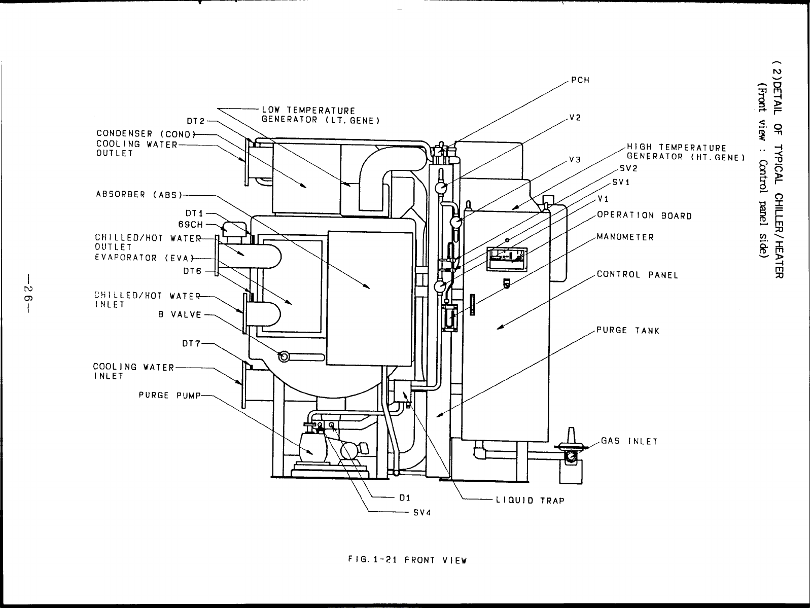
(2) DETAIT@ TYPICAL~IWWm(mm VIEW) ------- 26
(3) DETAITOF TYPICAL(llIUJZR/HEAllR(REARVIEW)---------- 27
(4) ~AIT w ~Im ~Iw~~(RI~ Vim) ------- 28
(5) ~AIT OF TYPICALGIILJ.JWHE4TER(IJFTVIEW)-----------29
(6) TYPICAL~= pm -----------------------:----------------------30
(7) TYPICALBURNER,GAS‘IRAINANDB. CONTPANEL-----------32
(8) m .......................................................................34
1.4 S4FETYDEVICES---------------------------------------------------------------37
(XII.UD/HOTWATERANo~1~ WA~ ..........................37
(1)
~~~ ~~ -TfJR ......................................37
(2)
BURNER---------------------------------------------------------------------38
(3)
MOTUR--------------------------------------------------------------------------38
(4)
U1’HRS ------------------------------------------------------------------------38
(5)
--------------------------------------------------------------25
—l–
Page 5
1.1 THEPRINCIPLEOFABSORPTION
(1) WHY DOES A HEATINGCHILL ?
I
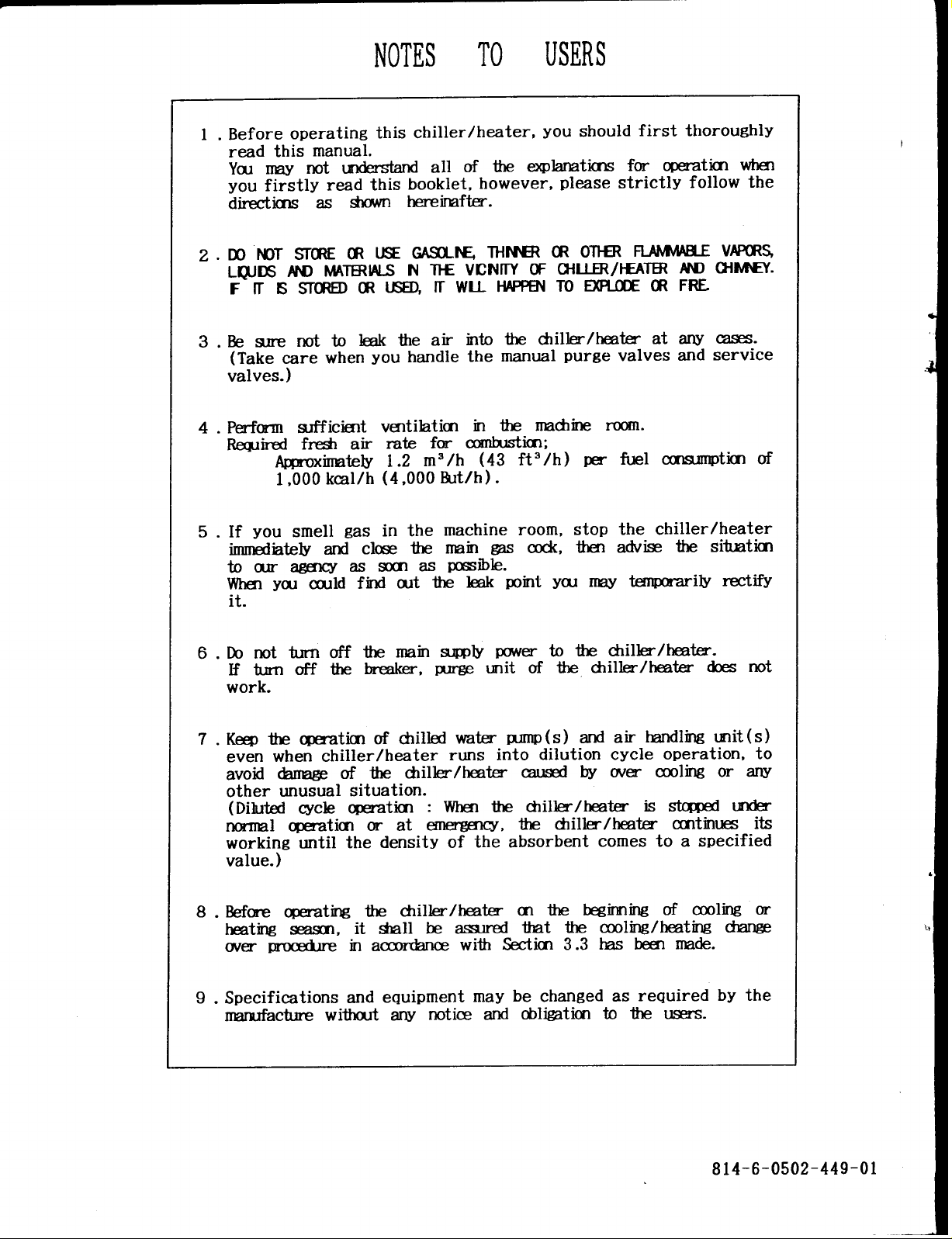
The cooling means keeping the room temperature lower than outside temperature. AS
shown Fig.1-1, operate to carry the heat from the room with a lower temperature (28”C,
82”F) to the open air with a higher temperature is required.
heat cannot move from alowtemperature side toahigh temperature side. So, to
transmit the heat as oppposed to this law (principle), some way (apparatus) is
necessary.
That is, a heat pump (chiller) is used topump out thehear from low
temperature one asifawater pump isused todraw upthewater from adeep well.
But, in the nature, the
IU l~C AI I-IUGU-I-U
COOLING LOAD
(82 “F) (90 ‘F)
AIR CONDITIONER
FIG . 1-1 HEAT FLOW
+
HEAT FLOW
–2–
Page 6
The typical c+iller using an electric as a operation
curry the heat in Fig.1-2 is an electric turbo chiller
heat energy is an absorption chiller.
power source as a conveyer to
and the typical chiller using a
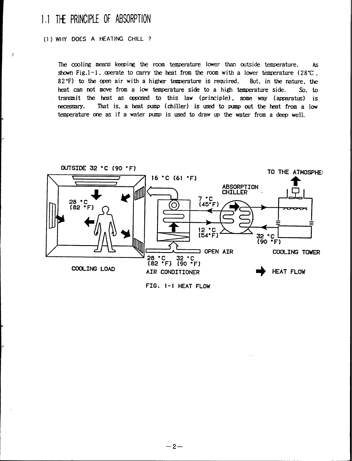
Chilled water is made by using the latent hear released byaliquid asitevaporates.
We can find this principle through our experience in a daily life.
having an injection, after applying as alcohol for disinfection on the arm, we feel
thepartofarm cool..
heat from thearmwhen itevaporates.
we sweat in a hot day or bytaking exercise.
automatically controlled by the evaporation of sweat which takes theheat fromthe
body.
necessary to return to liquid for using vaporized liquid.
compressor is used in anelectric turbo chiller and anabsorbent isusedin an
absorption
The
absorbing the vaporized solution. To recover
concentrating Process of the absorbentis required.
natural gas, steam or hot water.
A chiller also uses an latent heat of evaporation
chiller.
absorbent decrease
Because. the alcohol is heated by body's temperature. took the
And another sample is that we feel cool when
Because, the body temperature
But in a chiller, it is
the absorption power when it becomes diluted solution by
the absorption power, the heating and
Asheat source itis used by
For example, when
For this purpose, the
n
:&KOWEIJ:PERATIRE SIDE
I
A GRAIN OF HEAT
FIG .1-2 HEAT FLOW AT CJ30UNG
iv
HIGHER TEt4PERATuRE
ENERGY
SIDE
–3–
Page 7
(2) TI-E PRlNCIPLE OF ABSORPTION
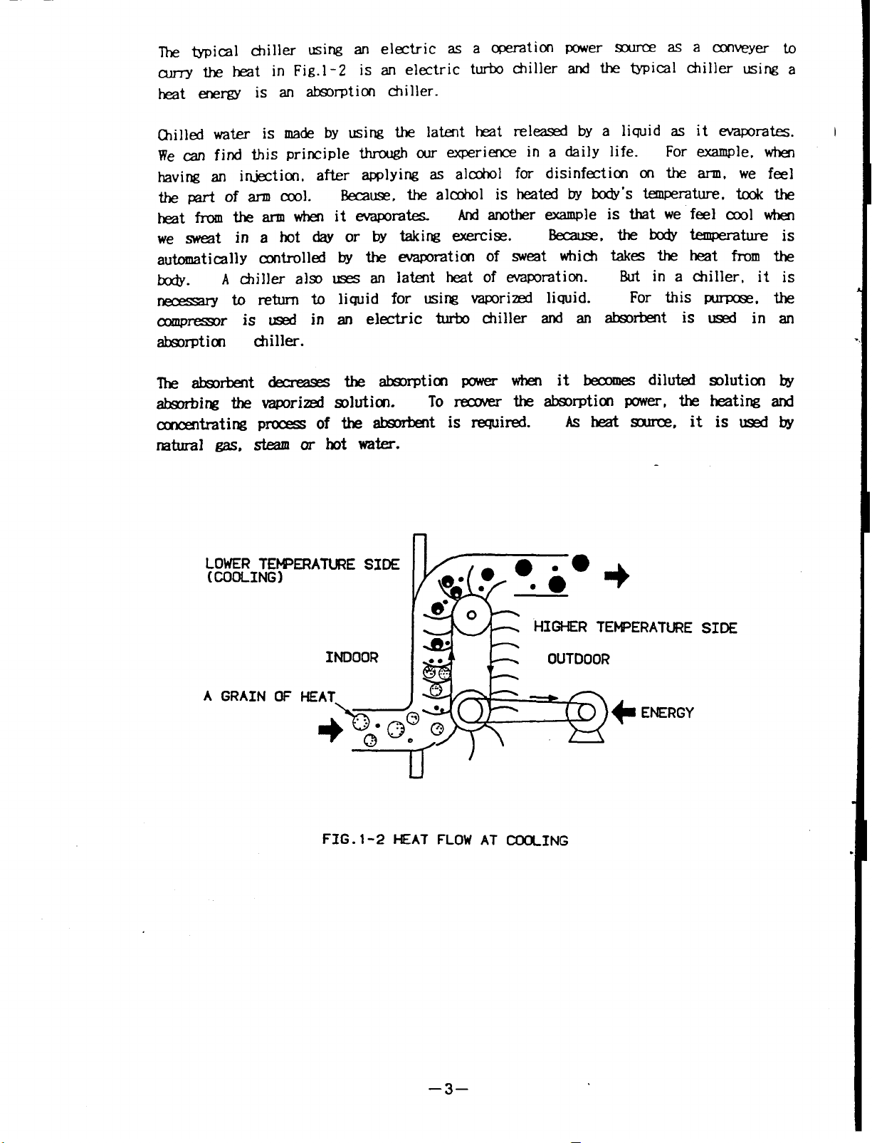
Install heat transfer tubes in a closed vessel and put a dry silicagel (Silicagel is
high quality absorbent material) in it as shown Fig.l -3.
vessel tomake avacuum
with the pressure
of approx. 6.5mmHg (1/4 inchHg). Drops of
water are allowed to fall on the heat transfer tubes (Evaporator).
vacuum vessel evaporates at5-C (41 ‘F) .
The water takes an evaporation heat from the
water intheheat transfer tubes, when it become vapor.
Take out an air in the
The water in the
(Such liquid is called a
refrigerant and shown as a refrigerant liquid or a refrigerant vapor for the
following. )
silicagel, a vacuum
As this evaporated refrigerant vapor is absorbed immediately by a
is kept inside the vessel.
Onthe other hand. the water in the
heat transfer tubes becomes chilled because the heat equivalent to the exaporation
heat is taken.
impossible to keep a vacuum
But, when the silicagel reaches the limit of absorptiono it
in the vessel and chilled water can not be obtained.
WATER
(REFRIGERANT)
is
CHILLED
WATER
WATER
tiEAT
I k P’=
~lcAGEL
TRANSFER
TUBE
FIG. 1-3
–4–
Page 8
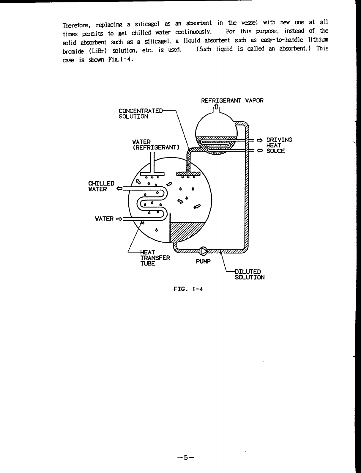
lherefore, replacing a silicagel as absorbent
lithiu
times permits to get chilled water continuously.
solid absorbent such asasilicagel,
bromide (LiBr) solution, etc. is used.
a liquid absorbent such as easy-to-handle
(Such liquid is called an absorbent.) This
case is shown Fig.l -4.
REFR~GERANT VAPOR
CHILLED
WATER
in the vessel with new one at all
For this purpose, instead ofthe
DRIVING
HEAT
SOUCE
WATER
‘+31LUTED
SOLUTION
FIG. 1-4
–5–
Page 9

Drops ofLiBr solution are allowed
solution absorbs refrigerant vapor.
refrigerant vapor, it is diluted and decreases
chilled water can not be obtained.
in continuously.
At this stage, the diluted solution isheated bydriving heat
to fall (Absorber) inside the vessel. The LiBr
But, when the absorbent once absorbs the
ability to absorb. Resulting in the
This means that concentrated solution must be fed
source (natural gas, steam orhot water:Generator). The heat causes thesolution to
release the absorbed refrigerant and also
reconcentrates the solution.
The refrigerant vapor which is relased from the solution when heated is cooled in a
seperate vessel (Condenser) tobecome
liquid refrigemnt.
Drops of this water are
again introduced into the vacuum vessel and recyled. This is shown Fig.l -5.
COOLIN
WATER
e ~R;ING
FIG. 1-5
Put@
C=
SOUCE
Page 10
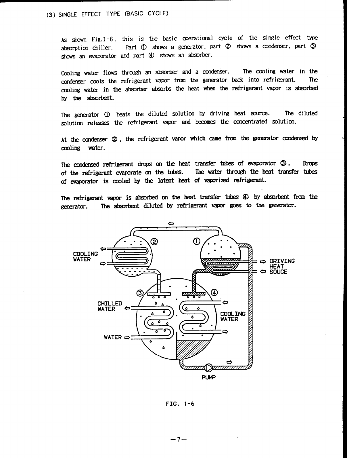
(3] SINGLE EFFECT TYPE (BASIC CYCLE)
AS * Fig.l -6.
absorption chiller.
shows an evaporator
Cooling water flows
condenser—cools the
cooling water in the absorber absorbs the heat when the refrigerant vapor is absorbed
by the absorbent.
The generator 0 heats the diluted solution by driving heat source.
solution releases the refrigerant vapor and becomes the concentrated solution.
Atthe condenser (2),the refrierant vapor which came from thegenerator condensed by
cooling water.
The condensed refrigerant drops onthe heat transfer tubes ofevaporator(3).Drops
of the refrigerant evaporate on the tubes.
of evaporator is cooled by the latent heat of vaporized refrigerant.
f--=--n
,— . .
The water Through the heat transfer tubes
The diluted
/?h@
COWING 1-, -
c=-&-=s /.” ”-w
WATE
~.\
I*-=
d
‘----’’--”=44 ~
CHILLED
WATER
WATER
(“~>” ‘ “ ‘WATER
COOLING
FIG. 1-6
—7–
Page 11
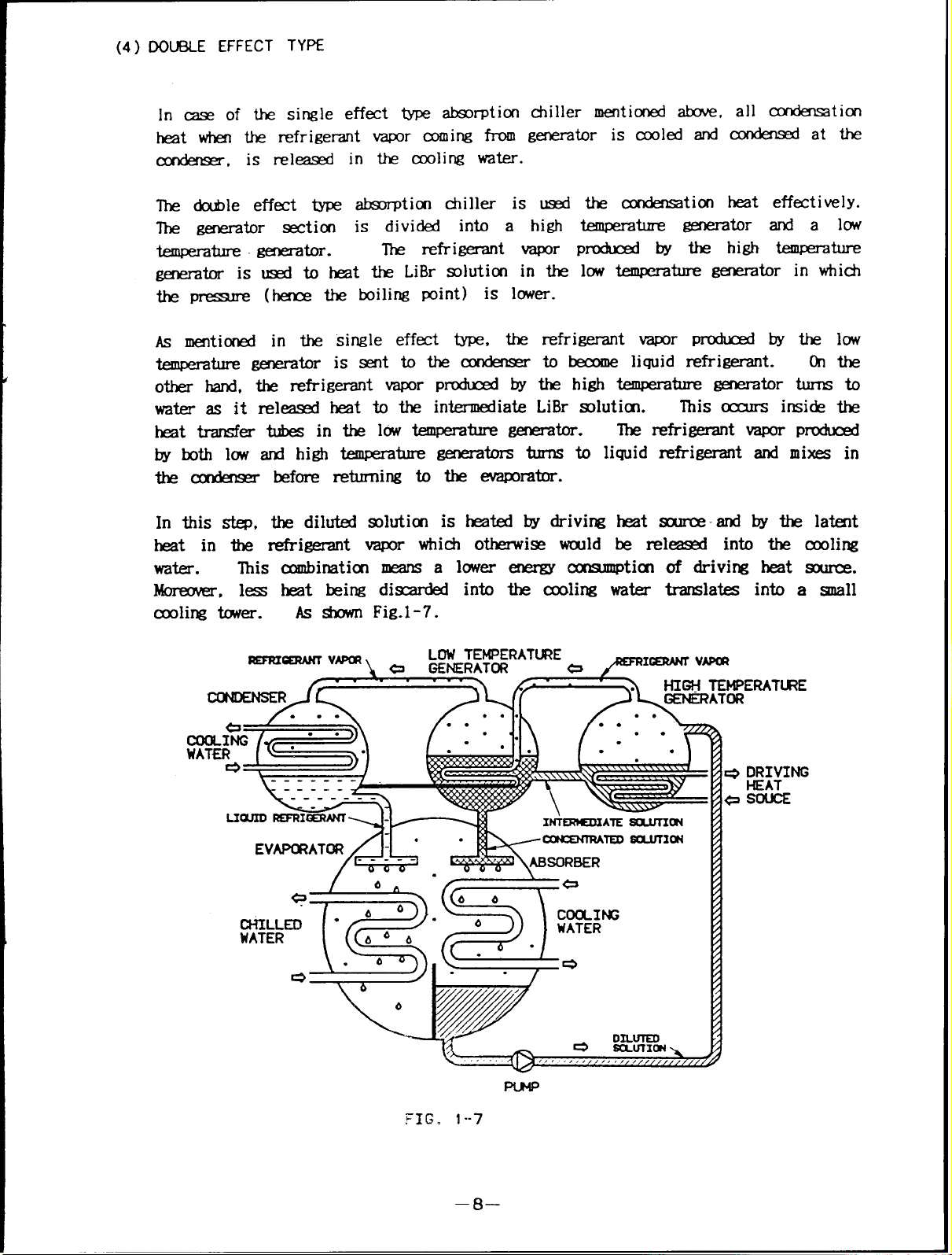
(4) DOU8LE EFFECT TYPE
In case of the single effect type absorption chiller mentioned above
heat when the refrigerant vapor coming from generator is cooled and
all condensation
condensed at the
condenser, is released in the cooling water.
The double effect type absorption chiller is used
The generator section is divided into a high
temperature generator.
The refrigerant vapor
generator is used to heat the LiBr solution in the
temperature generator and a low
produced by the high temperature
low temperature generator in which
heat effectively.
the pressure (hence the boiling point) is lower.
As mentioned in the single effect type, the refrigerant vapor produced by the low
temperature generator issent tothe condenser
to become liquid refrigerant. On the
other hand, the refrigerant vapor produced by the high temperature generator turns to
water as it released heat to the intermediate LiBr solutitn.
heat transfer tubes in the low temperature generator.
The refrigerant vapor produced
This occurs inside the
by both low and high temperature generators turns to liquid refrigerant and mixes in
the condenser before returning to the evaporator.
In this step, the diluted solution is heated by driving heat source by the latent
heat in the refrigerant vapor which otherwise would be released into the cooling
water.
This combinatiom means a lower energy consumption of driving heat source.
Moreover, less heat being discarded into the ceding water translates into a small
cooling tower. As shown Fig.1-7.
‘~ ‘-\ a GENERATCR
LDW TEMPERATL8?E
@ -x~ ‘-
DRIVING
HEAT
–8–
Page 12
(5) COOLIK WATER
Cooling water flows through an absorber and a condenser.
The cooling water takes the heat which the LiBr solution absobs the refrigerant vapor
at absorber.
This means the aborbent is cooled by cooling water.
The refrigerant vapor from the generator is cooled by cooling water.
The lower temperate of cooling water
a)
The absorption power of LiBr solution is strong at the lower temperature
cooling water.
condensed temperature of refrigerant downs.
low.
AS the boiling temperature (generator temperature) of the LiBr solution downs
when the condensed
decrease.
It is not acceptable
b)
This means save energy.
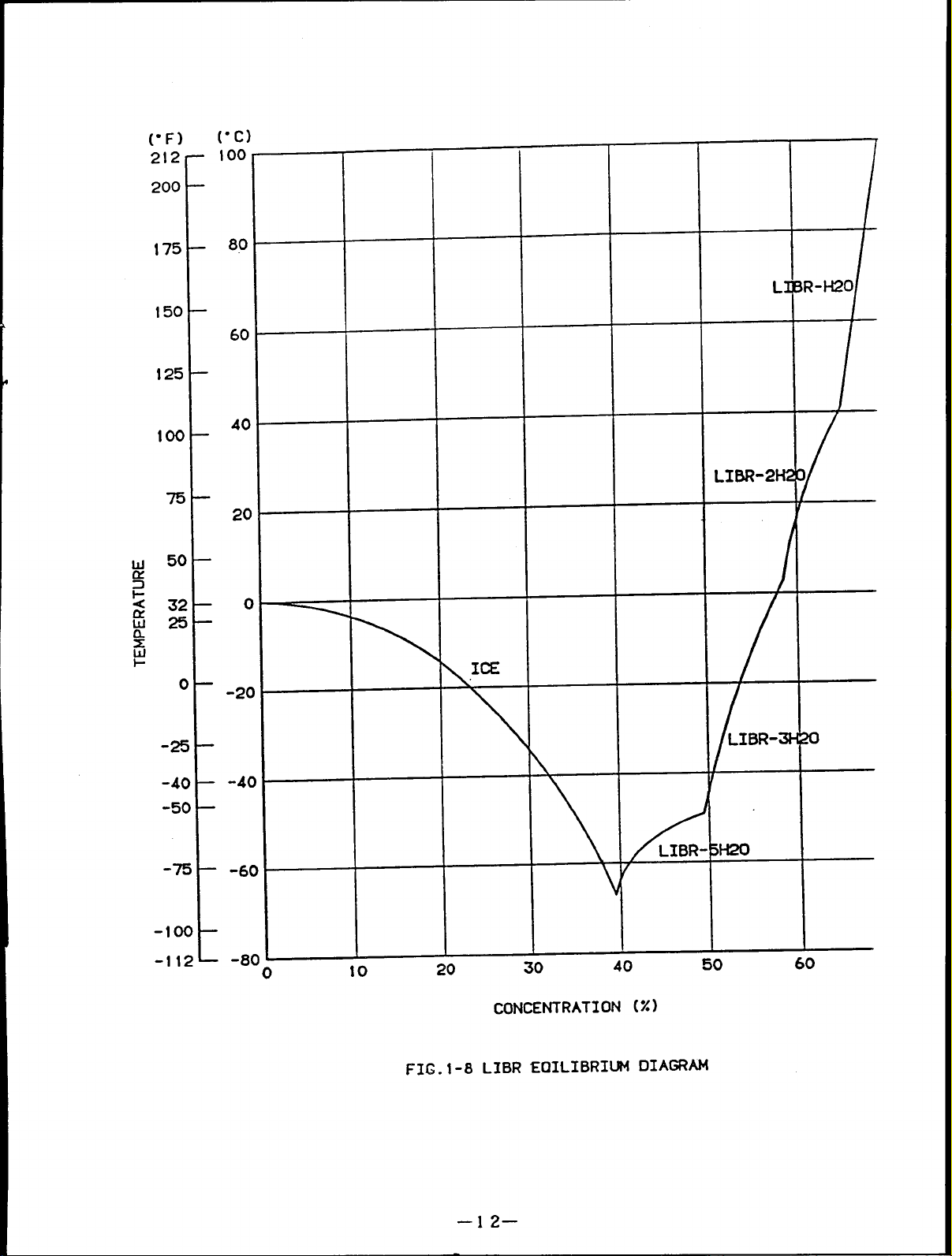
As shown Fig.1-8, a
LiBr solution of
temperature. For
When the temperature ofcooling water inthe condenser
Therefore condensed pressure
pressure is low, calolific value of driving heat source can
that the temperature of cooling water is too low.
few LiBr dissolves with water at low temperature.
high concentration becomes crystallization under the lower
example, it is crystallized with concentration” of 65% at the
temperature lower then 42C (108F) with concentration of 60%
lower than 17C (63°F).
Chiller has some problems when cooling water temperature becomes too high
c)
When the temperature of the cooling water becomes high, the absorption power of the
LiBr solution decreases.
temperature and wastes much fuel.
The chiller can not get the normal chilled water
Therefore. to prevent this, the maintenance for
cooling water system (equipment and control) and water treatment are required.
of the
is low.
becomes
lhat is, the
at the temperature
d)
Water treatment of
cooling water
The water treatment of the cooling water is an important factor for the chiller. If
the water quality is no good, scale adheres to the inside of the heat transfer tubes,
resulting in the decreases transfer heat effect and waste fuel.
Asthe heat transfer
tubes may become corroded, itisrequired to fully take care of the water treatment.
–9–
Page 13
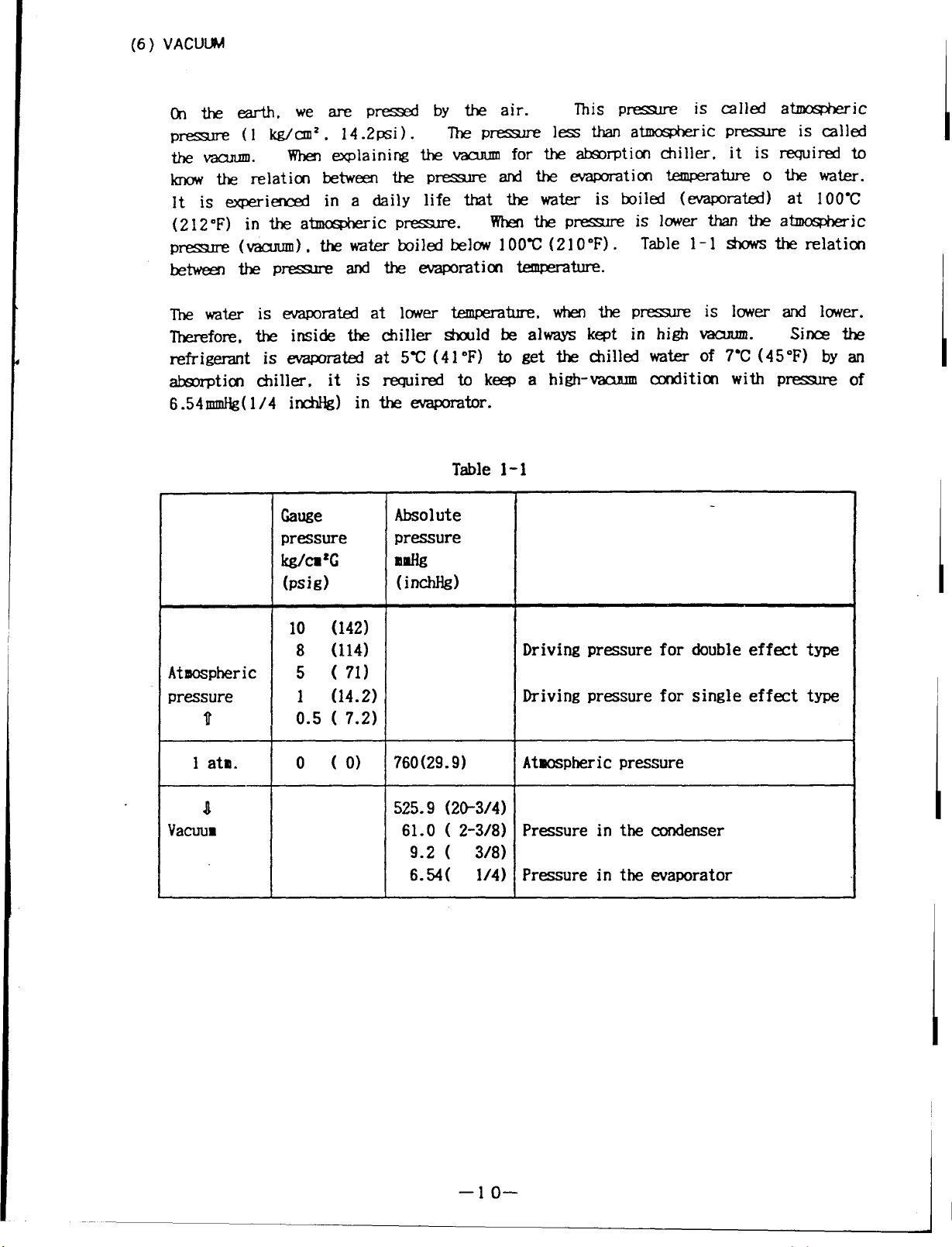
(6) VACUUM
Onthe earth, wearepressed by the air.
pressure (1 kg/cm2, 14.2psi). The pressure
the vacuum.
know the relation between the pressure
lt is experienced in a daiily life that the water is boiled (evaporated) at 100C
(212”F) in theatmospheric pressure.
pressure
between the pressure
Ihe
Therefore, the inside the chiller should be always kept in high vacuum.
refrigerant is evaporated at 5C (41 oF) to get the chilled water of 7C (45F) by an
absorption chiller,
6.54mmHg(1/4 inchHg) in the evaporator.
(
water is evaporated at lower temperature, when the pressure
When explaining the vacuum
vacuum), the water boiled below 100C (210”F). Table 1-1 shows the relation
and the evaporation temperature.
it is required to keep a high-vacuum condition with
Table 1-1
Gauge
pressure pressure
kgh’e
(psig)
Absolute
mldk
(inchM)
for the absorption chiller. it is required to
and the
When the pressure
This pressure
less than atmospheric pressure
evaporation t.emperature o the water.
is lower than the atmospheric
is called atmospheric
is called
is lower and lower.
Sines the
Pressure
of
10 (142)
8 (114)
Atmospheric
pressure 1 (14.2)
u
1 ata.
n
Yacmm
5 ( 71)
0.5 ( 7.2)
o (o) 760(29. 9)
Driving pressure for double effect type
Driving pressure for single effect type
Atwpheri c pressure
525.9 (2&3/4)
61.0 ( 2-3/8) Pressure in the condenser
9.2 ( 3/8)
6.54( 1/4) Pressure in the waporator
I
I
–lo–
Page 14
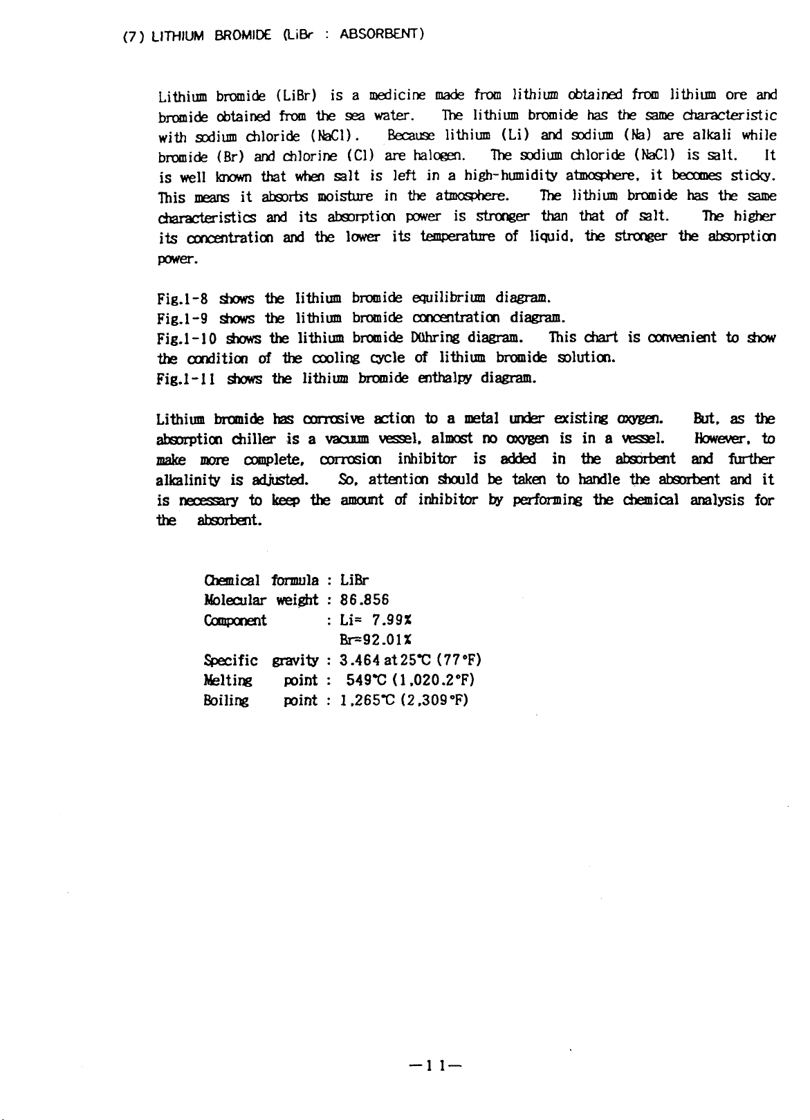
(7) LITYIUM BROMIDE (LiBr : ABSORBENT)
Lithium bromide (LiBr) is a medicine made from lithium obtained from lithium ore and
bromide obtained from the sea water.
with sodium chloride (NaCl) .
Because lithium (Li) and sodium (Na) are alkali while
brumide (Br) and chlorine (Cl) are halcgen.
The lithium bromide has the same characteristic
the sodium chloride (Ml) is salt. It
is well known that when salt is left in a high-humidity atmosphere. it becomes sticky.
This means it absorbs moisture in the atmosphere.
The lithium bromide has the same
characteristics and its absorption power is Stronger than that of salt.
its concentration and the lower itstemperature of liquid. thestronger the absorption
power.
Fig.1-8 shows the lithium bromide equilibrium diagram.
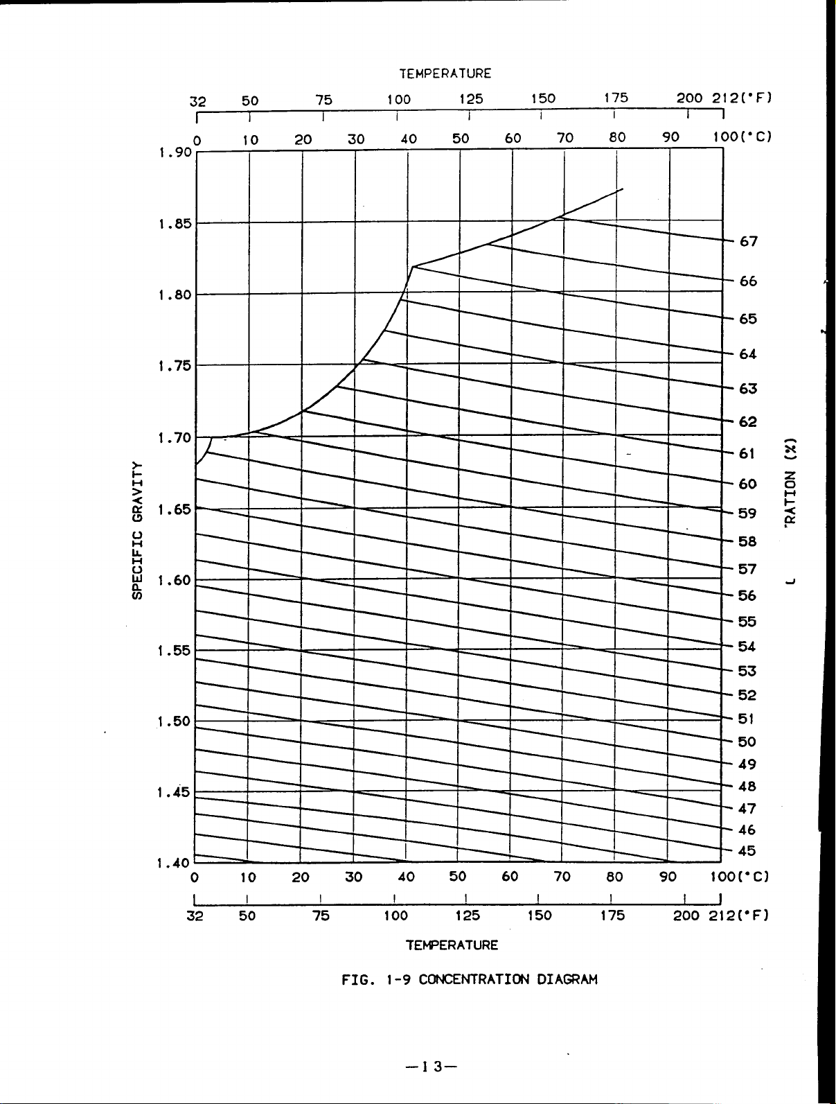
Fig.1-9 shows the lithium bromide concentration diagram.
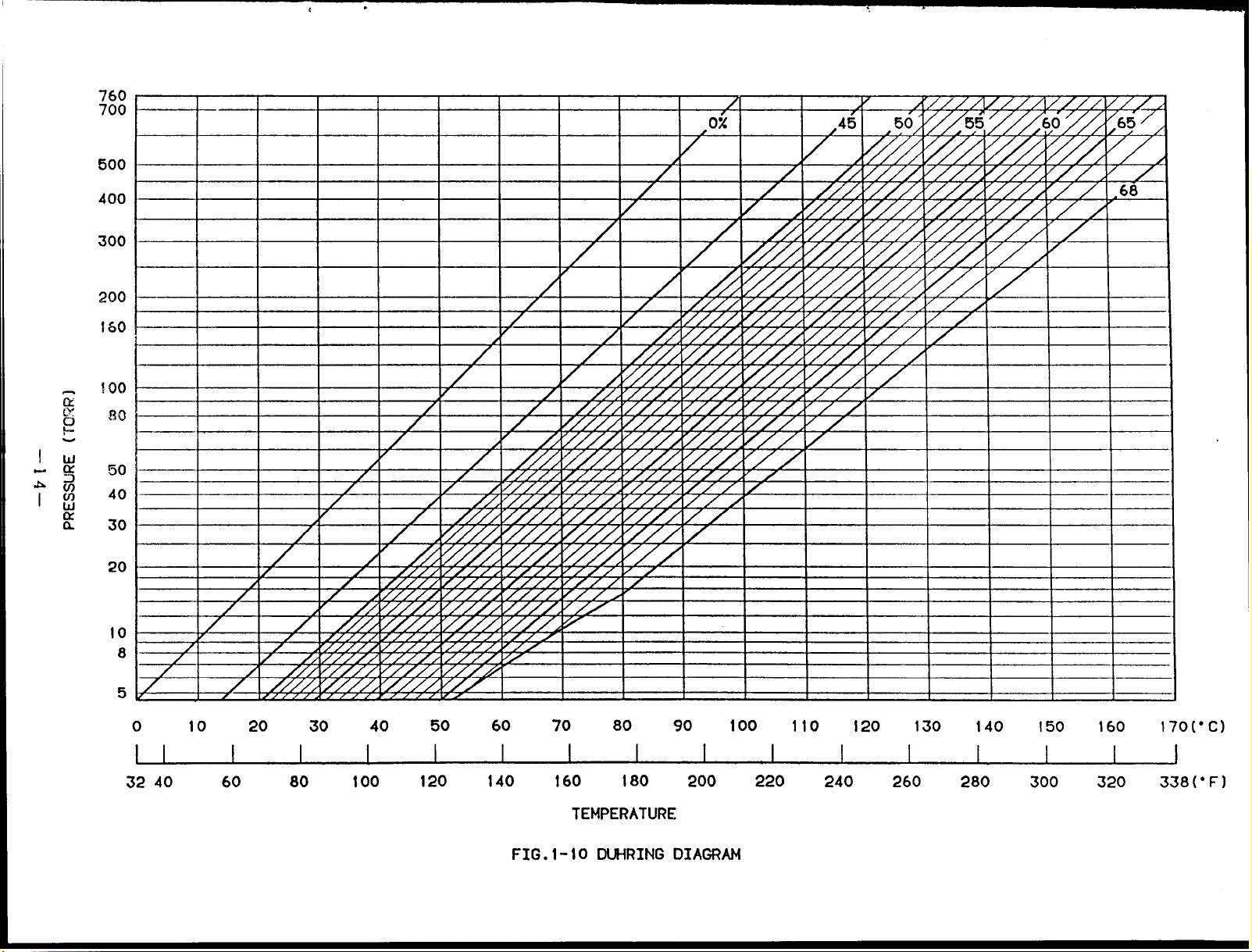
Fig.1-l0 shows the lithium bromide DUhring diagram.
This chart is convenient to show
thecondition of the cooling cycle of lithium bromide solution.
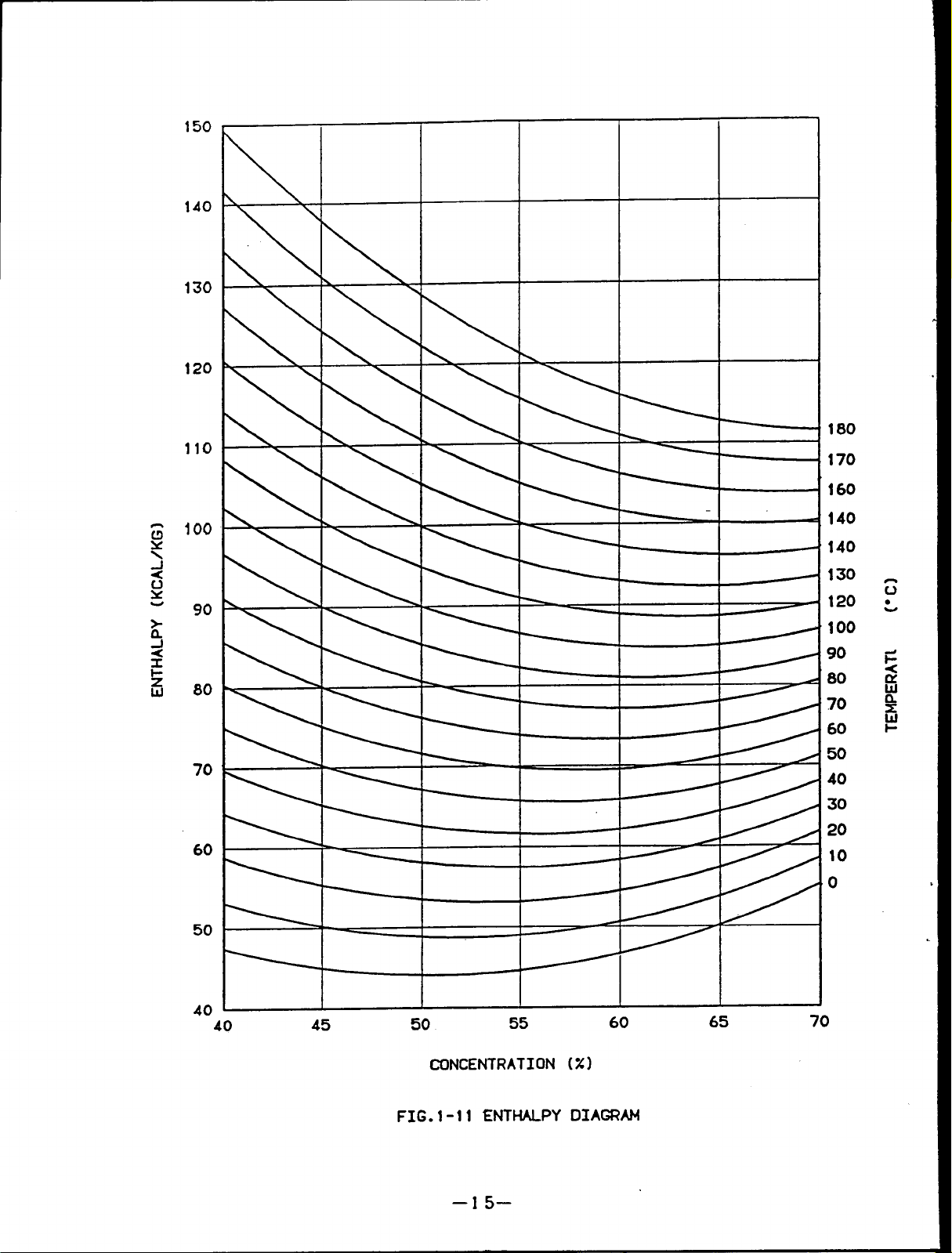
Fig.1-l1 shows the lithium bromide enthalpy diagram.
Ihe higher
Lithium bromide has corrosive action to a metal under existing oxygen.
absorption chiller is a vacuum vessel, almost no oxygen is in a vessel.
But, as the
However, to
make more complete, corrosion inhibitor is added in the absorbent and further
alkalinity is adjusted.
So, attention should be taken to handle the absorbent and it
isnecessary to keep the amount of inhibitor by performing the chemical analysis for
the absorbent.
Chemical formula : Li13r
Molecular weight : 86.856
Component
: Li= 7.99%
Br=92.01%
Specific gravity : 3.464 at25C (77”F)
Melting
Boiling point : 1,265C
point :
549C ( 1,020.2”F)
(2,309Φ)
–11–
Page 15
(“F)
2!2
200
(“c)
I 00
17!5
150
125
10C
5(
x
80
60
40 ‘
20
0
-20
-lo
-2!
-4(
-5’
-7
-40
-60
-80
10
20
CONCENTRATION (X)
FIG.1-8 LIBR
30
EOILIBRI~ DIAGRAM
40
50
60
–12–
Page 16
TEMPERATURE
1.90°
1.85
1.80
1.75
1.70
32 50
10
-
75
I
I
100
I
125
I
150
I
20 30 40 50 60 70 80 90
I I
175
I
1
200 212(”FI
I
1OO(”C)
I
67
66
65
64
63
62
61
60
I
1.65
1.60
1.55
1.50
1.45
1.401
59
58
m
57
56
l=+
1
I
55
54
53
52
-1
51
50
49
48
47
46
45
0
10 20 30 40 50 60 70 80 90
100[”CI
32 50 75
FIG.
100 125 150
TEt@ERATURE
1-9 CDNCENTRATICN DIAGRAM
–13–
175
200 212(”F)
Page 17
;::
500
400
300
200
160
!cm
f30
50
40
30
‘z
J21
20
10
8
5
0
32 40
10 20 30 40 50 60 70 80 90
60
80
100
120 140 160
TEMPERATURE
FIG.1-10
180 200
DUHRINGDIAGRAM
100 110 120
220
240
260
130
280
140
150
160
300 320
170(”C)
338(°F)
Page 18
150
140
130
120
110
— 160
100
90
k -.
80
70
60
170
50
40
40
45 50
FIG.1-11 ENTHALPY DIAGRAM
55
CONCENTRATION (%)
–15–
60
65
70
Page 19

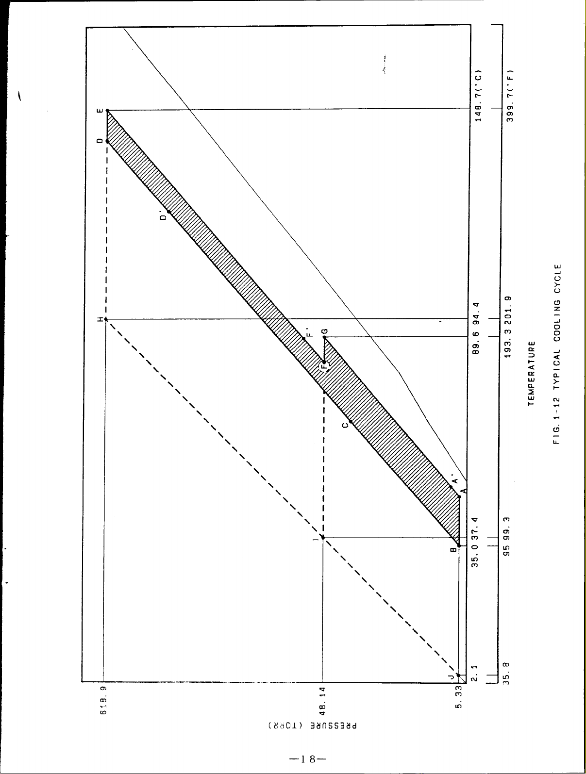
r
(8) COOLING CYCLE
An example for the actual driving cycle of double effect type is explained using the
Duhring diagram.
A Bshows the absorption process in theabsorber.
a)
The absorbent with concen-
tration of 63.6% at point A absorbs the refrigerant vapor from the evaporator as it is
cooled until 36.3-C (97.3”F) by cooling water, then becomes diluted solution with
concentration of 58.1% at point B.
The pressure of this point is 6.31mmHg(torr) which is equal to the saturation vapor
pressure of water at 4.3C (39.7°F) (cross point on
the chilled water at 7C (44.6°F) can be produced in
Therefore, the higher the temperature of the cooling
internal pressure (equal to the evaporator internal
evaporation temperature of refrigerant becomes high
the saturation liquid line) , so,
the evaporator.
water, the higher the absorber
pressure) .
As a result, the
and chilled water can not be
obtained.
B+ C+ D”shows the temperature rise
b)
process under the fixed concentration when
the diluted solution pass through the low
D’+D+E shows the heating and concentrating process inthe high temperature
c)
generator..
The diluted solution at point D’ is heated until point D.
the refrigerant vapor and
is concentrated. Then it becomes the intermediate
It releases
solution of 61.1% at point E and finishes the first stage of concentrating.
The pressure at point E becomes approx. 707.lmmHg(torr).
the pressure of 55.7mmHg(torr) in the condenser
temperature of cooling water.
That is, the pressure inside the low temperature
determining it according to the
(This pressure
depends on
generator has to be performed at the temperature higher than 91.1C(196”F) of the
concentrated solution obtained from the cross point with the concentrated solution
of 63.6%. Whensetting to 97.9C (208.2 “F) by making this as AT 6.8C (12.2”F) , the
pressure of the high temperature generator becomes 707.lmmHg(torr).
d)
--16–
Page 20
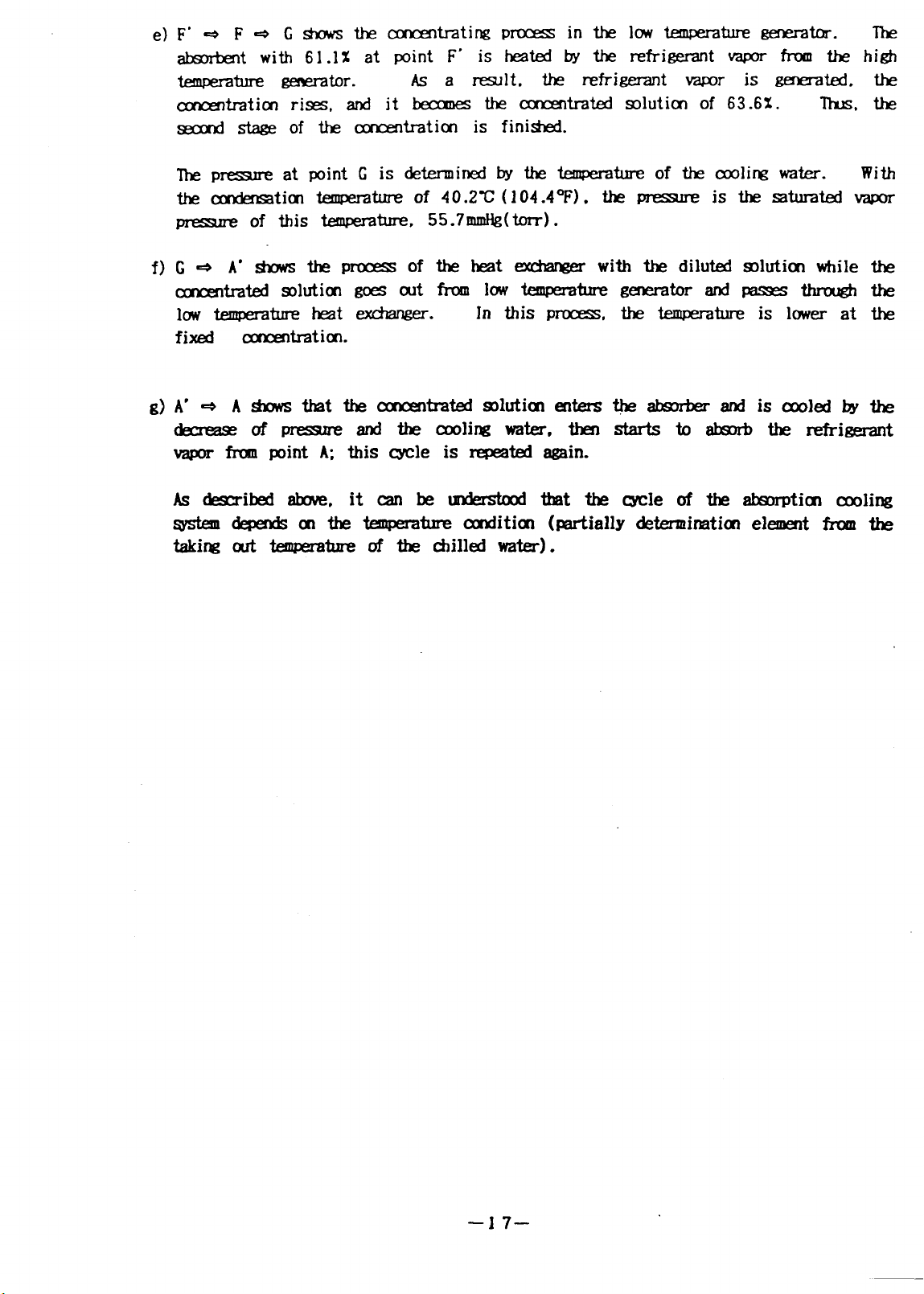
e
absorbent with 61.1% at point F’ is heated by the refrigerant vapor from the
temperature generator.
concentration rises, and it becomes the concentrated solution of 63.6%. thus
second stage of the concentration is finished.
As a result.
the refrigerant vapor is generated.
F+F+Gshows the
The
high
the
the
conce
The pressure at point G is determined by the temperature of the cooling water.
the condensation temperature of 40.2C (104.4”F). the
pressure of this temperature. 55.7mmHg(torr).
f)
A’+Ashows that the concentrated solution enters the absorber and iscooled bythe
g)
decrease ofpressure and
vapor from point A; this cycle is repeated again.
Asdescribed above, itcanbeunderstood that the cycle of the absorption cooling
system depends onthe temperature condition (partially dertermination element from the
taking out temperature of the chilled water).
With
pressureis thesaturated vapor
thecooling water, then starts toabsorb the refrigerant
–17–
Page 21
w
-1
cl
z
-1
t-
ti
-. —
v,
m“
.,
CfJ
u
e
C6
u
—18—
.-,
m
It+
Page 22
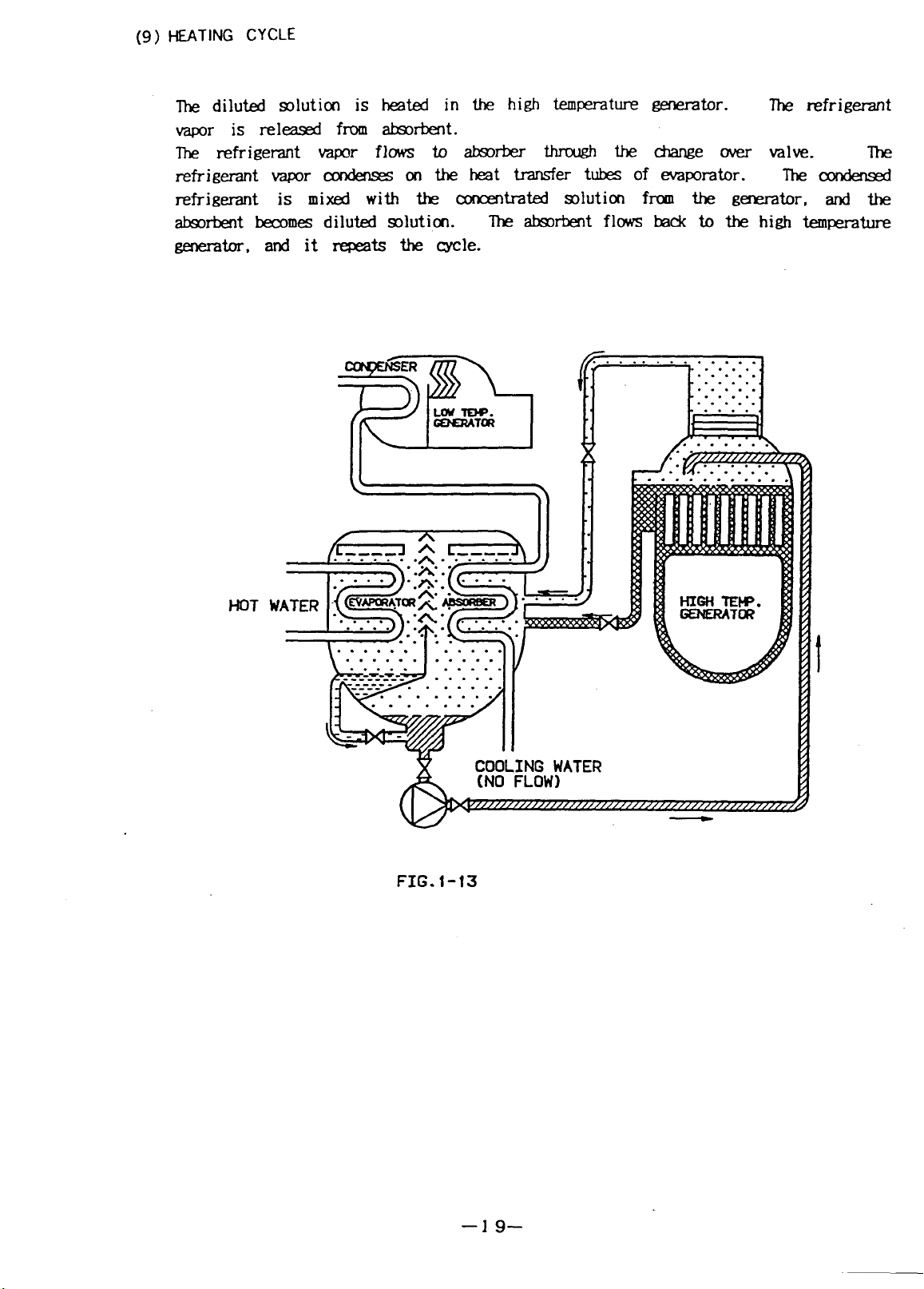
HEATING CYCLE
(9)
The diluted solution is heated in the high temperature generator.
The refrigerant
vapor is released from absorbent.
The refrigerant vapor flows to absorber through the change over valve.
refrigerant vapor
condenses on the heat transfer tubes of evaporator. The condensed
The
refrigerant is mixed with the concentrated solution from the generator, and the
absorbent becomes diluted solution.
The absorbent flows back to the high temperature
generator, and it repeats the role.
ER
LtM W.
~TU?
m
HOT
w
t
FIG. f-13
–19–
Page 23

I
N
7’
6
G
I
CHILLED
INLET
PURGE I
UNIT
I
I
t
COOLING WATER I )
OUIL T—
t
II
Ii n JJ15Ld
—
I
I
I
I
I
I
I
I
I
I
L!Kx__d3cH
mcoNcENTRATEO SOLUTION
=INTERMEo IATE SOLUTION
~~OILUTEO SOLUTION
REFRIGERANT PUMP
012
n I
Cotjofi
. . . . . .
L
/wl
/
/
B VALVE
1
[-J REFRIGERANT
[-] REFRIGERANT VAPOR
I I
——
——_
“T
LOW TEMP. GENERATOR
I
.< ‘ “
w
DT 7
‘P
_+
——
——
—
——— __
—
— — _ _ _ _—_—_—_
t
COOLING WATER’
LuL___
L 81 ABSORBENT PUMP
~OPEN
MCLOSE
..
1-
63GH ~
(II
km
I
I
I
I
I
I
I
I
I
I
I
REa_Ns
—
—
—
—
—
——
—_ ___ ___ _
—-l
—
— —
I
I
I
I
I
I
-H ‘
G ‘xcHANG”-
(THIS PUMP IS PRC)VIOEO ON
MOOEL OC-23 TO OC-83 ONLY)
LOW TEMP.
HEAT EXCHANGER
FIG. 1-14 COOLING FLOW CHART
Page 24

Evapaator
a)
The refrigerant isdispersed on the heat transfer
through the heat transfer tubes ofevaporator
vaporized
Absorber
b)
refrigerant.
tubes of evaporator.
Chilled water
is cooled by the latent beat of
FIG. I-15
–21–
Page 25
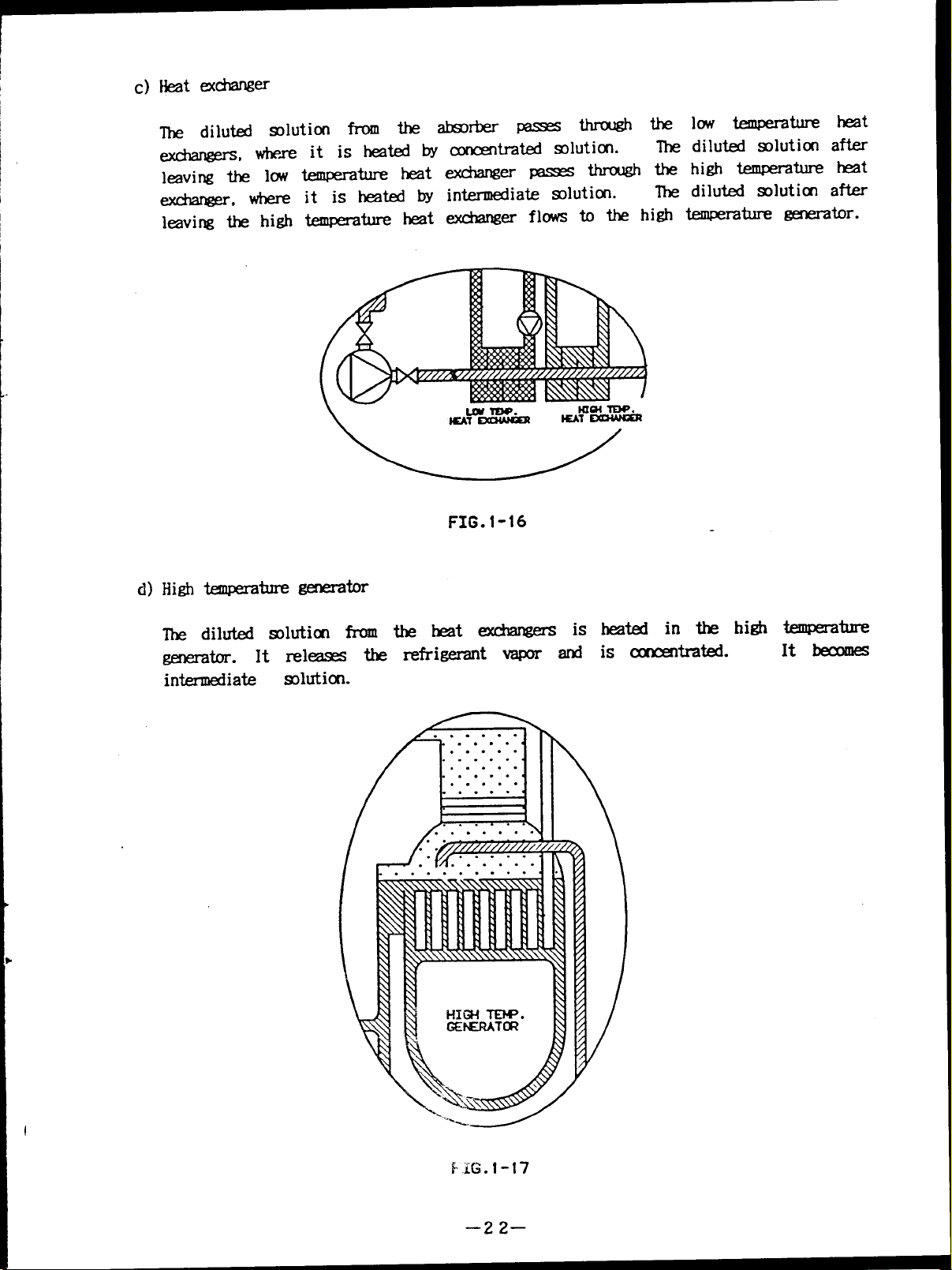
low temperature
the
diluted solution
The
high temperature
the
diluted solution
The
heat
after
heat
after
leaving the high temperature heat exchanger flows to the high temperature generator.
FIG. I-16
The diluted slution from the heat exchangers
is heated in the high temperature
generator. It releases therefrigerantvapor and is concentrated.
intermediate
solution.
It becomes
EiG.l -17
–22–
Page 26
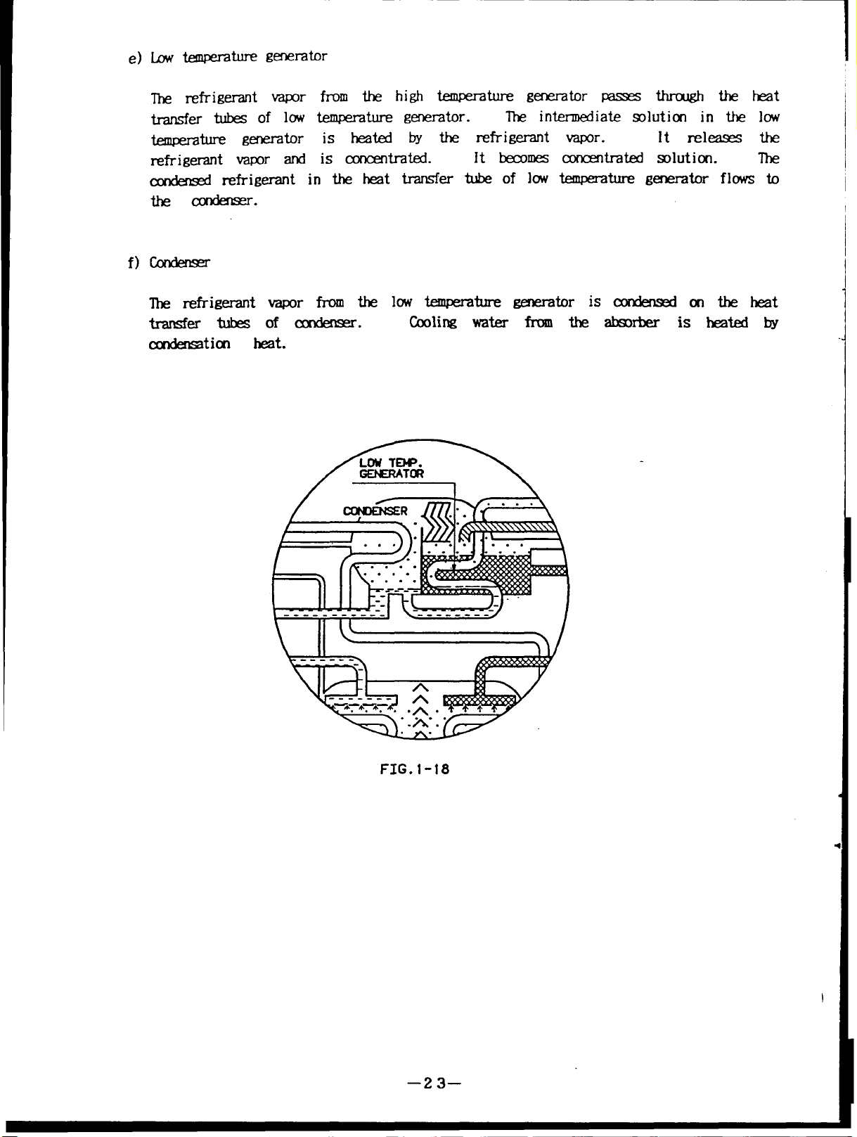
The refrigerant vapor from the high temperature passes through the heat
transfer
temperature generator is
tubes of low temperature generator.
heated by the refrigerant vapor.
refrigerant vapor and is concentrated.
The intermediate solution in the low
It releases the
lt becomes concentrated solution. The
condensed refrigerant in the heat transfer tube of low temperature generator flows to
the condenser.
f)Condenser
The refrigerant vapor from the low temperature
transfer tubes ofcondenser.
Cooling water
condensation heat.
generator is condensed
from the absorber isheated by
onthe heat
FIG.1-18
–23–
Page 27
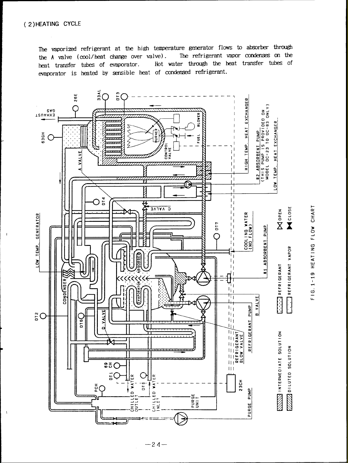
( 2) HEATING CYCLE
The vaporized refrigemnt at the high temperature generator flows to absorber through
the A valve (cool/heat change over valve).
—.-
transfer tubes of evaporator.
heat
Hot water through the heat
The refrigerant condenseson the
transfer tubes of
evaporator is heated by sensible heat of condensed refrigerant.
Svfl
‘HX3
m
:
k——————— —
‘? ?
———————
.
v>y\\.,..\\\\\\.>\\\.\
il
\
.
.
B
0
——T
I
0-
. . .
,
UJ
z
4
>
.-
. . .
. .
yr---
0<
u>
<
w’,nff!j‘!
~
I
r. m, —
‘“’”mr~
Zll 111~
1111-11
III
r
I
1
L
II 7 II ~~ II II
\
\
Y
1X1
II 1111
II 111[
,
1
1
II
—
t$---l’
,1
1;
II
.
—
!1
I
I
I
3-
--J
>1
UJ
>
A
-1
>
m
1
z
i!
t-
4
u
x
n
0)
.
I
.+
cl
u
.,______ .=
–24–
u
1-
2
Page 28

m
I L
)LplIr“
.,
n
u
F
r
c
C/?
+
m
>
~
o
z
t
!!!
‘CONTROL PANEL
PURGE UNIT
FIQ. 1-20 ILLUSTRATION
I
‘HIGH TEMPERATURE GENERATOR
I
~GAS TRAIN
$
L BURNER
Page 29
—
PCH
I
w
T
LOW TEMPERATURE
CONOENSER (CON,
,12-T
COOLING WATER
OUTLET
“sORBER(ABs)AlxlM
CHILLEOiHOT
OUTLET
EVAPORATOR
CH1iLEEJ/HOT
INLET
69CH
WATER--- r
(
EVA+
oT6—
WATE
B
VALVE
GENERATOR (LT. GENE)
\
‘/
OT7=
11/
,’
/“’-”
/
,V2
/-”
/“”
/
/vf
,OPERATION BOARD
,MANOMETER
,CONTROL PANEL
,PURGE TANK
SV2
Svl
HIGH TEMPERATURE
GENERATOR (HT. GENE)
M
xl
‘URGE‘uMp----k
FIG. 1-21 FRONT VIEW
‘L-- LIQU,D
TRAP
GAS INLET
+’
Page 30

( 3 )DETAIL OF TYPICAL CHILLER/ HEATER
(Rear
view : Burner side)
WE
no
zl-
wa
I-CY
n
3Y
OUJ
-lC!J
t<
m
0
n
4
>
1-
1-
\\k\
/
>
m
ml
W
I
.
u
rY
n
1-
a
&w
U.l (cl
Z3
–27–
Ck
5
a
CE
1-
m
a
C!Y
Page 31

( 4 )DETAIL OF TYPICAL CHILLER/ HEATER
(Right side view
: High temperature genmtor side)
m
J
z
a
w
1-
‘“d
an
>
Ida
~ >>
\
‘%
<
.w\
L1.1./F
o
d
>
u)
\
w
1-
zm JO
0< an
l-+ (J-)
J
)
)
>
-1
Otx
(no
-u-
Lua
>Z
-1=1
an
>
zm
0<
—
I-tu
a=
-1
Om
o-1o
-L
m
rY
m
Cd
+
Ci
IL
1
0’!
n
I
-J
w
z
a
o.
-1
0
w
t-z
G
L1
‘1
LLJn
>ZILJ
-13 >
-xn_l
>a
m>
zm -
0< v
l-ml
an
$CK
U-JO
—LA-
–28–
Page 32

CHECK VALVE
COOLING WATER
OUTLET
r
D VALVE
REFRIGERANT TANK
rOT’
*
SV9
I
N
T
1
1# .
I
1
1
CHILLED/HOT WATER
OUTLET
CHILLEO/HOT WATER
INLET
#2 ABS PUMP
P
-IsOLATION VALVE
FOR REF PUMP
L
ISOLATION VALVE
FOR REF PUMP
FOR Ill ABS PUMP
L
\
ISOLATION VALVE
81 ABS PUMP
FOR
NO. 1 ABSORBENT PUMP
ISOLATION VALVE
NO, 2 ABSORBENT PUMP
(82 ABS PUMP)
(81 ABS PUMP)
FIG. 1-24 LEFT VIEW
Page 33

(6) TYPCALCCNTROLP-
f
‘<
INDICATION LAMP
m
OPERATION BOARD
EMERGENCY
STOP SWITCH
II
‘“ CONTROL PANEL
/ HIGH VOLTAGE
FIELD W
/
CONTROL
FIELD W
I
b
II
RING OPEN
CIRCUIT
RING OPEN
NG
NG
FIT. 1-25 CONTROL PANEL
—3 o—
Page 34

/,/”
/’
/
/’-’-’
,’
.
,cONTROL BOARD
CONTROL RELAY
FAN MOTOR
,MODE SELECT SWITCH UNIT
\
,/
.
.
/’-” ‘“’ES
,
~ TERMINAL BLOCK
~ CONTROL TRANSFORMER
PoTENTIOMETER
FUSE HOLDERS
I
POWER TRANSFORMER
INVERTER
000
REACTOR
L
000
CIRCUIT BREAKER
/“”
,
WIRE CHANNELS
I //
I-’-J
w.,
[
FIG. 1-26 INSIDE OF CONTROL PANEL
I
‘-=--
.
--....
1.
.
‘“‘-\
.
~MAGNETIC CONTACTOR
~MAGNETIC coNTAcTOR
— REFRIGERANT PUMP
~ CONTRO CIRCUIT
~ MOTOR TERMINAL BLOCK
-~
=-..
NO. 1 ABSORBENT PUMP
NO. 2 ABSORBENT PUMP
MAGNETIC CONTACTOR
PURGE PUMP
MAGNETIC CONTACTOR
TERMINAL BLOCKS
HIGH VOLTAGE
FIELD WIRING TERMINAL BLOCK
= INTERNAL WIRING
\,
‘\
CONTROL CIRCUIT
FIELD WIRING TERMINAL BLOCK
–31—
Page 35

( 7) TYPICAL BURNER, GAS TRAIN AND BURNER CONTROL PANEL
MA NI HOLD PRESSURE GAUGE
/
I-7’ / “
14
,MODULATUIN MOTOR
/BUTTERFLY VALVE
URNER BLOWER
/’
P
FIG. 1-27 TYPICAL
BURNER
CONTROL
PANEL
BURNER
MANUAL GAS SHUTOFF VALVE
I
REGULATOR
n
~1 g
/
2N0 SOLENOID VALVE
FIG. 1-28 TYPICAL GAS TRAIN
MAIN SOLENOID VALVE
/
BUTTERFLY VALVE
—32–
Page 36

ON-OFF SWITCH
\.
CALL FOR
HEAT LIGHT
“’/,, \
“/ / \
‘\
‘w,
OJOIO
IGNITION LAMP
FUEL ON LAMP
ALARM LAMP
i\
\
~llllt !
!
,/’
‘//
/
6’ @&j
/FUEL TRANFER SWITCH
/
,,
/MANUAL/AUTO
SELECT SWITCH
FIRING RATE
CONTROLLER
\\
\\
‘\,
\
AIR FLOW
SAFETY SWITCH
///
\
MAGNETIC CONTACTOR
\
\ OVERCURRENT RELAY
FIG. I-29 BURNER CONTROL PANEL
\ TRANSFORMER
/
\ BURNER
(FLAME
CONTROLLER
SAFEGUARO)
“–33–
Page 37

(8)SYMBOL
a) Chiller/heater
EVA
AM
CCND
HT.GENE
LT.GENE
HT.EX
LT.EX
#l ABs PuMP No.1 Abmrbent w
#2 A5s PuMP NO.2 Absxbent Pump
REF
constrwtion
symbol
Evawrator
Nxwber
High temperature fmemtir
Imw temper-alum mhemtor
High temperature heat exchanger
I.m temperature heat @&langer
FuMP Refrigerant m
Name
b) Temperatum smsor
s@Xd
DT1
DT2
Chilled/hot water ~tlet (%illed/hot water outlet pipe
Cooling water outlet
bcation
before
flange.
Cooling water outlet pipe
before
flange.
—
DT3 High temperature generator Back side of high tenuxrature
~t.or.
DT4 b t.enwemture generator
Intermediate mlution pipe of
LT.GENE outlet.
-—
DT5 Refrigerant pipe of mndensx
outlet.
—
DT6
.
DT7 Cooling water outlet
Chilled/hot water inlet
Chilled/hot water inlet pipe
before flarge
Cooling wak inlet pipe
before
flange.
–34–
Page 38

I
c) Sensor
d) Valve
Name
23CH
26E
Electronic controller
Exhaust gasikrmmXat
El J12J13J?4 Gmednr dutim level
electrod
33AL
beratur soluticn level
cmtrol board switch
63GH GmeAor presmre switch
69CH I ~illedhot water flow Witch
PCH
symbol
A valve
Palladium cell heater
Name
holing/hmting &al-l@ W=
A valve
Location
Incllxkxl opemticn board
Flue Pipecnthe HrLENE
Solution level box beside the
high t.empemturw ~tor
In the control panel
Near the
duticn level box
Chilled/hot Wati mtlet P@
ropal them tank
Location
Refrigerant vapor pipe bAind
the control panel
B valve
cooling/hinting change W=
B valve
C valve
cooling/hinting change wetC valve
D valve Cooling/hinting dangle w=
D valve
V1
V2
V3
V4 IRefrigerant blow valve
No.1 ~ valve
Ib2 ~ valve
No.3 mrge
valve
Under theevaporator heack?r
(Front side)
E!ehind the
invef-ter ml
NmrtheevapomtQ- hea&T
llesidethe~tank
E!esi&ttK? *tank
Bd&?thepLm3tank
EvaPcmtorside
—3 5—
Page 39

e) Service valve
SW-M
Name
Svl Service Mve for maintenance
Location
Besi&!the PlJr13e tank
-—
SV2 Service wdve far
SV3 Sewice valve for refrmt
SV4
Service valve for diluted
solution
SV5 Service valve for intermediate
solution
SV6
Service valve for ancmtratd Beside thelowtempemtln-e
solution
-.
SV7 Service valve for gmerator
Inamxm?ter BeSick them tank
h the refrigerant pipe
IbX-the No.labmrflmt pump
(outlet Pipe of #l m HJMP)
Besi& Ihe high tenwerati
heat ex&angel-
hmt eXc&nger-
On the solution level box
~-
SV8 =i~ valve for gmetator
maintmance
SV9
Service valve for heat
exchanEEr
mainterlanm hmt exdanger’s hemkr
Bottcmofthehightempemture
~b
E?esi& of high temperature
Svl 1
Setvice valve for Blladium
TcQthe~ tank
cell
f) IkmlP=
ml
D1
I
Name
IhnmY for diluted soluticn
Location
outlet pipe of#ll AIISFuIvlP
after check nlve
D2
Damper for intermediate
solution
D3
kmPer for Cmcmtrated
solution
.
g) Sight glass
symbol
Name
Mermdiate dutim Pipe
betwem ~EX and
Cmcmtratd Smtial pipe
LTIXNE
betwxm LTGJ3JEand LT.EX
Location
—
SGl
sight gk for refrigerant
Evaporator
level
—
SG2
sight glass for @lemtcr
Hfgmed.orbox
SG3
sight glass far kurw!r flare
.— .-—
—36–
Behind the gmezatcu-
Page 40

1,4SAFETYDEVICES
( l) CHILLED/HOT WATER AND COOLING WATER
No
Item
1 Interlock of chilldhot water pump
—
2 interlock of cooling water pump
3 Few flow ME of chiWcJ/hot water
4 Chilled water freeze protection
(Unv-d of chilled water outlet *.)
5 High-cut of hot water outlet temperatu.m
6 M-cut of cooling water inlet teuwerati
( 2)
HIGH TEMPERATURE GENERATOR
Setting point
Alarm indication
Mication lamp
klication lamp
50 % Indication lamP
2 .5°C (36 .50F) Itiication lamP
70T (158”F)
19°C (66.2°F)
Indication lamP
Indication lamp
after 30 min.
—
No
7 High-cut of generatnr temperature (Cooling)
8 High-cut of generator temperature(lleating)
Item Setting point Alarm indication
165°C (329°F)
130”C (266”F)
9 High-cut of generator pressure
10 High-cut of gened.or mlution level
+
—
11 *cut of gerxmtor ~lution level
—
12 High-cut of exhaust gas t.ewerature(bs) 300”C (5720F)
13 High-cut of exhaust gas temperature(Oil) 350”C (662°F)
14 Crystallization
(High-at of =lution concdration)
protection
65%
after 10 min.
—
Indication lamp
Indication lamP
Indication lamP
Indication lamP
Itiication lamP
Indication lamP
–3 7–
Page 41

(3)BURNER
No
15 Flame failure
16 Abrmnal combustion
(4)
MOTOR
No
Ovemlrrent relay of No.1 akrbent pump Rated ampemge
17
Ov
18
19
ermrrent relay of NO.2 akxberlt pump Rated amperage
0/
erarrent relay of refrigerant pump Rated amperage
Item
Item
Setting point
——
Setting point
Alarm
indication
Indication lamp
Indication lamp of
flame failure
AlamI indication
Indication lamP
Indication lamP
Indication lamP
( 5)
(Iv
20
[
OTHERS
No
21
22
23
24
[
ercmrent relay of burner blower
Item
Inverter
protection
Power interruption protect icm
Chattering protection of flow switch
Rupture di&
MM ~e
Indication lamp
Setting point Alarm indication
Indication lamp
100 m =.
I
I
3 sec.
I
Indication lamp
I
–38–
Page 42

SKKItf2 OMATMI
Si33VON2 OFIRATION--------------------------------------------------------------------39
2.1 OFiTtATIONBOARD------------------------------------------------------------40
CONTENTS
Page No.
.
(1) ~A~ ~
(2) INSITUTm OF ~S---------------------------------------------------42
2.2 lXMFIRAluRESEITING ""----------"-----"--"----"----------"--"------"--"---43
(I) ~AJL ~ M~~ ........................................................43
(2) ~ ~ ~ D~~~ D~y ................-................44
(3) %1-1’IM ~ --------
2.3 SIZJ?-DIAGKSI’ICSF’UNCI’ION---------------------------------------------51
(1)
SLF-DIIMNXTIGS FUhKXION -------------------------------------------51
o~T~ ~~.- .. . . . .. . . . . . . . . .. . . . . . . . ..__.. _. . . . . . . ...40
------------------------------------------------46
(2)ERtURMESSAGEBY SllF-DIAGNO~D--------------------------52
2.4 PRD31RATIONFOR STARTW------------------------------------------------54
( 1) ~IRMATION W
(2) CONFIRMATION~ ~~ po~s .................................55
(3) ~IRMATION OF U4AlWEOVIR VAL~--------------------------55
(4) ~wT~ ~ ~~m-- .........................................56
OHRATIONSWI’IUES--------------------------54
2.5 OPEiATION -----------------------------------------------------------------------58
CXXIJNGOFIRAT~ -------------------------------------------------------58
(1)
HEATIMOFIRATION-------------------------------------------------------6O
(2)
OPIRATIONBOARDCURINGOPIRATION-----------------------------62
(3)
COMBUSTIONTIME ~-------------------------------------------------65
(4)
CONTROLTIME CHART---------------------------------------------------67
(5)
MAXIMJM~ ~-----------------------------------------------69
(6)
mm CONIROLOF #l A6s
(7)
FR12X1’ OF U-IW
(8)
—3 9–
WATIRTEMFEWTURE-----------------------71
FUMP-’--------”-------------------70
Page 43

21 OPERATIONBOARD
(
l) DETAIL OF OPERATION BOARD
m--,
......... .. ................----
; TMZRATORE
I 0 GENERATOR
[ 0 EXHAUSTGAS
; 0 CH/HT W CWLET
:o CO WINLET
!mz&ilzi&’5 ‘::’ ~
!WATER ALARM
!ocHv TRm’.
:0 CH/NT W FLIX RATEO
~Ot?JWTEMp.
;O CO W FLIX RATE O BURNDi BLOWER O
\oHTw TEMP.
OPERATIONREtORD
0 C/H OPERATION
0 C/H ON-OFF
0 REF. PUMP OPERATION ,....................
0 COHINJSTION
MOTOR ALARM
0 REF. PUMP
Ail AK. PUMP O
0 112A6$. POMP O
OCHWTENP. ::
OHTWTEUP. [j
.........................
v .... .. . .. . . . . . ... .
GENERATORALARM
PRESSORE
o
SOLUTIONLEVEL
TFNPXDNCENTNATION O CM PRFMJN.E !
EXHAUSTGAS TEMP.
Cz..: @.;
SET POINT ~
,,
:;
::
.. .... ....
;TOP RUN
0 0 CHILLER/HE4TER
O 0 REF. POMP
O 0
#l ABS. PUMP
o 0 #z Ms.
0 0
0 0 BURNER BLOWER
SYSTEM AL4RN (1NTERLOCK)
0 CH W FUMP
o co w FunP
0 AIR FAN
PUMP
PURGE PIMP
CD -:
,.CZ3 ;-m a.:
:,
...........
~o COOLINC
;0 HEATIM
......... . .
-----.---------l––--i
OPERATION REMOTE
r––n c––~ ..
STOP
r-––l ~–’1 j
COMBUSTIONALAN ;
O AIR FLOW ~
O FLAKE FAILURE ;
0 BURNER
0 ALARM
IEZER STCP
————.
——
.........
... ....
!-CD
FIG. 2-1 Typical C&ration Board
A
Page 44

(i) Monitor
This area has some indication lamps (Red) which indicate temperature of several
points, operating hours,
temperature, and digital display (Red) which indicates data of lighted item.
(2) Select key
There is “SELECT”key for selection
insequence bypush thekey.
automatically after approx. 1 minute.
chilled and hot water parameter.
@ Equipment RUN-STOPindicator
This area has some “RUN” indication
(Red) which indicate conditions of
@ Operation mode indicator
The indication lamp
indicates operaton mode.
@ Combustion indicator
The indication lamp
lights during combustion.
number of burner ON-OFF times and setting point of
of display data item.
The item is displayed
The item returns to generator temperature
There are” A”and” V”keys forgetting of
lamps (Green) and some “STOP" indication 1amps
the equipment.
@ Alarm indicator
The indication lamp
flickers when the chiller/heater has abnormal condition.
@ Alarm item indicator
The indication lamp
@ Operation mode mode key
indicates alarm item.
There are keys for chiller/heater cperation.
@ Alarm buzzer stop key
There isbuzzer stop key when the abnormal condition ofthe
chiller/heater.
—41–
Page 45

( 2) INSTRUCTION OF KEYS
“ SELECT”
I
For the use of item selection for display.
The item is displayed in sequence
Change the item automatically when
by push the key.
You push the key continuously more
than 1second.
“A” For the use of change of setting Point.
Setting number is increased by push the key.
Increase
the number automatically when You push the key continuously
more than 1 second.
“v”
For the use of change of setting point.
Setting number is decreased
bythekey.
Decrease the number automatically when YOUpush the key continuously
more than lsecond.
“ OPERATION”
Operate the
chiller/beater by local mode.
The chiller/heater does not operate when the mode is set “Remote”.
The indication lamp on “OPERATION”key flickers when the male is set
“Local” .
For the chiller/heater operation, You must push the key more than
1 second ccntinuously.
This is protection of the chiller/heater.
Please Push the key continuously until flicker the indication lamp on
the key.
“ STOP” Stop the chiller/heater by local mode.
“STOP” key is accepted on either mode of “Local” and “Remote”.
The indication lamp on “STOP” key flickers when the stop signal is
accepted by push thekey.
For the chiller/heater stop, You must push the key over 1 second
continuously.
This is protection of the chiller/beater.
Please push the key continuously until flicker the indication lamp on
the key.
“
LOCAL” For the use of operation
on of the chiller/heater by “OPERATION”key on
the operation board.
not operate.
does
remote panel.
“ REMOTE”
When the mode isset
“Remote”,
the chiller/heater
For the use of operation of the chiller/beater by
“OPERATION”key is not accepted on “Remote” mode.
“ BUZZER STOP” For the use of stop of alarm buzzer when the
buzzer sounds by
abnormal condition of the chiller/heater.
I
-–4 2–
Page 46

2,2TEMPERATURESETTING
(1)
DETAIL OF MONITOR
I
TEMPERATURE
● GENERATOR
C) EXHAUSTGAS
0 CH/HT W OUTLET
C) CO W
INLET
OPERATIONRECORD
() C/H OPERATION
() C/H ON-OFF
0 REF. PUMPOPERATION
0
COMBUSTION
0 BURNER
ON-OFF
SET POINT
0 CHWTEMP.
0 HTW
TEMP.
● ‘F
I
: z
The data is displayed on the digital display by “SELECT”key.
indicated by indication lamp of item.
The data on the digital display is returned to generator temperature after approx.
1 minute automatically.
Fig. 2-2 is shown generator temperature.
The indication lamp after digital display lights according to unit of item.
Unit of temperature is “F ( Fahrenheit ).
3.
FIG. 2-2 Monitor
- 0 HOURS
OSTARTS
The item is selected by push on “SELECT”key.
C571
The selected item is
I
–43–
)
Page 47

(2) SEWN= (N TtE DGITAL DISPIAY
item is dimlwed in SEXWME
Sequene
K%%‘tiimtim1-
1 Gek&;emPerature
Exhaust gas
2
(EXI-lAw GAS)
3 Cb
4 Cooling witer
5 (%i 1lerkater
i 1led/hot water
out let temeratum
(CHm w m)
inlet temperature
WINIXI’)
(CO
operating hours :
(C/H CIPI33ATION)
temperature
Mmhka’.
Semmce ikms are as follows;
~le on the digital display
3
G G- =
(
300.0)
3 9
v w G
B
D G G
a
5. n
n
(
390.0)
(
44.0)
(
85.0)
( 1000)
6 Nmber of Chiller/heater
ON-OFFtimes :
(cm O?wFlv
Refrigerant pmm
7
operating hours
(R13?.FIRI!P0P13MTICN)
8
Combustion hours
(COMBUSTION)
9 BAmberof burner
ON-OFFt ims
(Buwm a+Om
z D
(
3 c E
( 900)
9
s G
(
z D G
( 200)
120)
950)
—44—
Page 48

Sequence
——.
10
——
11
Lighted indication lamP
——
Chilled water
temperature setting
for temperature
(CHW TEMP.)
Chilled water
temperature setting P z- G
for proportional
(CHW TEMP.)
12
13 Chilled water
Chilled water
temperature setting
for integral
(CHU
TEMP.)
_——
temperature setting
for differential
(CHWTEMP.)
Sample on the digital display
——. —
: B
[
d
4
4. D
Z2 a
:
(t44.0)
2.0)
(P
—
I
(1800)
E
(d 10)
14
Hot water
temperature setting
for temperature
k :
3
:- =
(HTW TIM’.) (t131.o)
15 Hot water
temperature setting
for proportional
(HTW TEMP.)
—
‘-1-6-”-
17 Hot water
Display sequence repeats No.1 thru No. 17.
Note) l.It will happen to display below number between No.1O and No.11.
This temperature which is controlled the chilled water outlet temperature by
external condition.
Hot water
temperature setting
for integral
(HTWTEMP.)
temperature setting
for differential
(HTU TEMP.)
“- ‘“””
..—.. ..— -.
——
F 5- Z
(P 6.0)
:
d
s G
(I 50) ~
3 ~
(d 30)
~
I
J
~(c
2.It will happen to display below number
This temperature which is controlled
external condition.
~(h,z,l)
–4 5–
46.4)
between No.14 and No.15.
the hot water outlet temperature by
.
—
Page 49

(3) SETTING METHOD
Chilled/hot water outlet temperature is mtrolled by digital PID (proportional.
Integral and differential).
temperature.
a) Chilled water setting point range
Setting item
Chilled water outlet
temperature
Proportional
Integral
Differential
Note) Temperati data sampling is 10 second interval.
b) Hot water setting point range
Setting item
Hot water outlet
temperature
::L 2.;:+
(1)
(D)
(t) \
41.0- 53.6 ‘F .-.
0
.—
o - 100s
I
I 104.0 -140.0 ‘F1 0.1-0.2 I
It is able to get chilled/hot water of stable
.—
:: -
- 2500 sec 10 sec P or PD action at O sec
1
- P or PI acticn at O sec
I
Range
step
I
1=
I
Remark
.—
—
Proportional
Integral
Differential
Note) Temperatum data sampling is 10 second interval.
Notice 1.
2.
3.
4.
5.
6.
-nij---p: ,00 sJ---T-
Please confirm the indication lamp of setting item before setting.
“A”and” V
If you change the setting during chiller/heater operation, chiller/heater is
controlled by new setting point soon.
Original setting point is set at factory.
Setting point of chilled water outlet temperature is for cooling mode.
And setting point of hot water outlet temperature is for heating mode.
Setting point is stored by non-volatile memory of semiconductor.
Therefore, setting point is kept continuously when power cut off.
(P) (
(1) I
2.0- 10.0 I 0.1-0.2 /
o - 2500 sec I 10 sec Por PDactionat Osec
1 secl Por PIactionat Osec
“ keys do not accept to cross the range number.
—.
Page 50

c) To take
an example((hilled water setting)
Setting item
. ..—
Chilled water outlet
temperature
Proportional
Integral
Differential
(t)
(P)
(1)
(D)
$
Setting procedure is as follows;
“ A “
2
‘ImlIII1
Original
+-
2.0 –
800 sec
—.. .— —
Iosefl
Target
———
46.0 “F
2.5
—.——
+----
——
t
900 S
40 Sec
‘p’ma=--l
se] ect the chi 11ed water temperatur~
setting(CH WTEMP.) by push the key.
The indication lamp of “CHWTEMP.”
1ights.
——
Push the “ A “ key.
Display data increases 0.1.
._L__-L-..-(t 44”2)
“SELECT” 1
4
~
(P
2.0)
“A”
5
‘EIIElll
(1’ 2.1)
“A”
6
EmIzIEl
(P 2.5)
Push the “ A “ key until 7.5.
If display data increases over 7.5,
push the “ v “ key.
data decreases 0.1.
..-
The display
Push the ‘“SELECT”key.
Display data indicates proportional
of chilled water outlet temperature.
.—
Push the “ A “ key.
Displw” data increases 0.1.
?ush the “ A
“ key until 2.5.
If display data increases over 2.5,
msh the “ V “ key.
The display
~ata decreases 0.1.
–47–
Page 51

No. Key
“SELECT’”
7
Digital display Explanation
Display data indicate; integral of
— ————
“A”
8
, &?”’’sELEon “Y -
J_
..—
(I 800)
I ~hi ]led water outlet
+
t,e~p~rat”r~o
———
‘ DmiiIEl ‘~’~;t:i;$;;es ‘0-
(1 810)
,
,.
~-- +
10
+
“SELECT”
, IItEiEl ~~ ~~ ; :;
If display data increases ove~ 900
~“nt~e’~sp~ay
.
.
“A”
9
Display data lndlcate~ differential
*7
(d 10)J
——
of chilled water outlet temperature.
11 “A”
~ 1‘:&;4i&&es 1-
I
(d 11)
L
12
“A”
I
~
(d 40)
If dlspla~ data increases ov~r 40
~~”~ “ :: ~ ‘nt~fli~p~~
data decreases 1. “
–48–
Page 52

an example{Hot water setting)
setting item
‘-.ter .+:-
temperature
Proportional
Integral
%
Differmtial
Procdure is as follows;
No.
—— .—
1
2
3
4
Key
“SELECT”
“ A “
“A”
“SELECT”
I
(t)
(P)
(I) – -
—.
(D) ~
6.0
50 s=
30 = 20 =
Digital display
&
(t131. o)
EImEIIl
(t131 .1)
EIImEl
(t134.6)
~
(P 6.0)
=1=
1:?’”
5.0
900 SEX
—. —
Explanation
Select the hot water temperature
setting(HT WTEMP.)by push the key.
The indication lamp of “HTW TEMP.”
lights.
——
‘:1%;:t$i:5J’es010 -
L-
—.
If display dat: increases ov&”57 O,
~~ ~ :: “ ~
‘nt~e’li~p]~
data decreases 0.1. ”
Push the “SELECT”key.
Display data indicates proportional
of hot water outlet temperature.
—
“v”
5
~
+
“v”
6
9
(P 5.9)
~J=2;;es 0’
If display data decreases ~l~w 5 0,
ti-
(P 5.0)
~~ ~~ ““:: ~
data increases 0.1. ”
“nt~~d~sp]a~
–4 9–
Page 53

No.
“nt~
7
__#_T..
Key
“SELECT;
A
“A”
Digital display
““m-;sE”a” “Y
(I 50) ~
~ ~~~~~~~$~~es ‘0-
.—.
(1 60)
I Display data indicate; integral of
hot water outlet temperature.
If display data increases ove~ 900
EuIIIiI,~~~~:::~
,.
:~1
“SELECT”
~
——
11 “v”
d ‘;~e;:;zies ‘-
‘k
12 “v”
(1 900)
(d 30) ,
(d 29)
——
data decreases 10. “
Push the “SELECT”key.
Display data indicates differential
of hot water outlet temperature.
Explanation
~ ~~i~i~~ ~z;~e~~~~
(d 20)
data decreases 1. “
–50–
Page 54

283 SELF-DIAGNOSTICS FUNCTIONS
(
1) SELF-DIAGNOSTIC FUNCTIONS
Self -diagxxtics
a) Some
indidim
FUWTCN
fmcticn darts, * the breaker of the chiller/hinter tum cn.
lamps light as - Fig.2-3.
Symbol O: Indication lamp does not light
Symbol ●
Symbol B
TEwmTtRE
0 CfNERAT~
ormALLsTc4s
Ooullrwm
Oalwlhlm
mm5zl:k55 “
VATTRALARM
● CHWTEW. ● Rm. F’lMP
● cW?fTw FUWmntilw. w
● CD WIWP.
● covmwm ● BLFuJm-
● Hrw TTMP.
: Indication lamp lights.
: lndication lamp of the key lights.
OPERATIONRKYRD
0 C/H cP!WT1f14
() c/H WCFF
0 RET. W cffJblTION
o mlKlmmN
Omm
KmRw GEMmm
● mEssmJ!
● scUJrlcN IJzWL ● mvl l!=’
● #2 Jws. fwK’
● -/CIXENRATICN
● EMML!STC4STEW.
m mlNr
OCHWTFMF’.
OtlrwTmP.
v
AIAFN
SRx’lw
● ● aiIulwHEAm
● ● Rm. FIM’
● ● al Ars. Fwr’
● ● #2 APs. PIJMP
● ● FIRCEFWF’
● ● EumTRRuMm
SYSml AIAml (Ir’mNmo
● ouHrwFIJw
● AIR FAN
ccuBusTIcNAuRm
● AIR FUM
● W FAIURE
● C4SPIURWU?
FIG. 2-3
Buzzer sounds 4times after1second ofturn onthebreaker.
b
Some indication lamp turn off after buzzer.
Self-diagnostics is worked.
c
Verson number isdisplayed onthe digital
self -diagnostics.
d)
error by self-diagnostics.
(Blew number
is for reference. )
Gnerator temperature is as shown;
UIEIzEl (,.,)
dis
Verson number isasshown:
(v 7.00)
chiller/heater’s specificatim.
digital display, if control circuit has no
.
—51–
Page 55

(2) ERROR MESSAGE BYSELF-DIAGNOSTICS
Error massage is displayed
on the digital display, when the error is found in the
circuit.
lncase of theerror, itis
necessary, please call to
If
necessay to call Sanyo’s service
Sanyo’s service represenative after memorized the error
representative.
message.
Power supply error
a)
This error massge is indicated the error of power supply to electronic controller.
The key access is not accept on this message.
It is necessary to call to Sanyo’s service
represenative.
(P-u))
Electronic controller error and setting point error
b)
message (on the digital display flickers)
(The
This error message is indicated the error of electronic controller or setting point.
Please call to Sanyo’s service
represenative with below error number.
It is not accepted the chiller/heater operation during indication of this message.
~(.rr.)
Kind oferrur mesage
~-----------------@ EYror rnmter
-“-1
}.............. @
— ------------
: ;“-{ 1------------- @ Error nuuber EU-2
::
-
;!
::
: ..............
●--------- @ Error nunber EU+-8
.......
----------- (3) I&ror nunber ERR-3
------- 6 FYror nmber EIR-5
---------- CDError nunber D?R-4
cDEI-rornumbermR-~
CDErmrnumkrmR-2
@Errwnumber ERR-3
(D Eh’-urnumber ERR-4
@ Ermrnumber E?R-5
@ Err0r~f33~-6
CDE-rOrnumkl- ERR-7
@Errurnumker EiRR-8
(Electrcmic cmtroller
(~~m mint err-or)
(Electrmic cmtroller
(Number of tiws data
(eating hours data
(Electrmic
(Etiic cGYtroIlet(Electrcmic ccdimller
:,
.......
‘------ hxlicate thekindofemr~
ERR-6
~or -r ~_~
(D Error nmber ITU+l
error) :
envr) :
error) :
err(r) :
cdroller
error) :
en-m) :
error) :
Call to service.
- the setting point and call
to service.
Call to service.
Call to service.
Call to service.
Call to service.
Call to service.
Cdl to service.
–52—
Page 56

Power failure error
c)
(lhe message on the digital display flickers)
This error message is indicated to return the power after power failure during
operation( include dilution cycle operation).
The power failure means not only power failure( include over 100 millisecond power
interruption) but also artifical power turn off the breaker.
If will happen to indicate this message when the breaker is turned on at first after
field wiring.
This error massage
d
Sensor error
(The message on the digital displav flickers)
This error massage is indicated the temperature sensor trouble.
Chiller/heater stops safety when high temperature generator temperature sensor( DT3)
and chilled/hot water outlet temperature sensor( DT1) are broken during operation.
the chiller/heater operates continuously, when other sensors(DT2, DT4, DT5, DT6 and
DT7) are broken.
Please call to Sanyo’s service representative.
~(~~r~)
Kind of error message
,----------------------------------------@ Error number SER-2 (DT2: Cooling water outlet)
_;:
I
10
~..;; , ,
— ,.....~ ;..,
is cleared when “OPERATION”key is Pushed.
But it is Possible to control bad condition.
.............-.
‘------------Indicate the kind of error message
:----------------------------------@ Error number SER-5 (DT5: Condenser)
~------------------------------@ Error number SER-3 (DT3: High temp. generator)
— -------------@ Error number SER-4 (DT4: Low temp. generator)
1---------- @ Error
—
‘---------------------------@ Error number SER-6 (DT6: Chilled/hot w.inlet)
...
number SER-1 (DT1: Chilled/hot w.outlet)
● ---------@ Error number SER-7 (DT7: Cooling water inlet)
Note) It is possible to change the displav data and *tting point on the digital displav
using & “SUET”,“-A “ and ‘“ V
Electronic controller error, setting point error,
error.
–53–
“ keys duriu- error massage ;ndicati& of
power failure error and smsor
Page 57

2.4 PREPARATIONfOR START UP
Please confirm
(1)CONFIRMATION OF
below items again before operation.
OPERATIONSWITCHES
a) Operation switches inthecontrol panell
~;C)U:OL REFRIGERANT BURNER COOL/HEAT
AuTO
MANUAL
~ CLOSE
\ \ \ \ \ \ 1
> pu~p
AUTO RUN COOL STOP
STOP
MANUAL TEST HEAT START
FIG.
CHANGE OVER PUMP
2-4 TYPICAL OPERATION SWITCHES
PURGE
@Gas
control valve mode select switch ------------------”AUTO" position
@ Gascontrol valve open-close switch -------------------”SKIP” position
@Refrigerant pump mode select switch
@Burner mode select switch
@Cooling/Heating change over
.....................
switch ----------------------“COOL”position for “COOLINGmode“
------------------- "AUTO" position
......... ..
“RUN- posistion
“HEAT” position for “HEATING mode”
@Pump purge operation switch
0 Auxiliary switch -----------------
b) Burner control panel
Burner ON-OFF switch -----------
-------------------------------”STOP"- position
---------------------------------oneither side
..................................
“ON” position
—54–
Page 58

( 2) CONFIRMATION OF SETTING POINTS
a) Chilled water temperature setting point
(Setting sample)
0 Chilled water outlet temperature ..... .................... 44F
@ Proportional
... .................. ................ . ---------------
@ Integral --------------------------------------------------------------800
@ Differential
b) Hot water temperature setting point
.... ....................... .... ..... .------ ----
(Setting sample)
@ Hot water- outlet temperature ................................ 131F
(2) Proportional
@ Integral --------------------------------------------------------------50
@) Differential
( 3) CONFIRMATION OF CHANGE OVER VALVES
No
Valve name Cooling mcde
-------------------------------------------------------"-"30
Heating mode
2
10
6
1 A valve close
2
B valve
3
c valve
4 D valve close
Note)
a) When the cooling water is kept in the chiller/heater,, D valve opens.
.
b) When the cooling water is drained from the chiller/heater, D valve
closes.
2. In heating mode, Please close isolating valves of cooling water inlet and
outlet.
close
close
——
see note 1.
–55–
—
Page 59

(4 )CONFIRMATION OF EQUIPMENT
a) Combustion equipment
@ Open the main and pilot gas cocks in the gas train and the gas valve of supply gas
@ Never smell gas around burner and gas train.
@ Linkage between burner and gas train.
b) Water system
@ Some valves for chilled/hot water line.
@ Some valves for cooling water line.
@ Other system line.
c) Cooling water inlet temperature
0 holing water inlet temperature
@ Take care that the cooling water inlet temperature is kept above 66 ‘F
d) Electric wiring connection
@ Interlock of chilled/hot water pump
@ Interlock of cooling water pump
Note) Interlock signal is detected by energized DC 24V from the chiller/heater.
Please select the contact resistance within 100Q .
(Please Separate other power line. )
–56–
Page 60

e) Remote signal connection
No Signal name
1
Answer hxk simal
for operation
—
2
S@ indicitial kunp
3
Operation indication
lamp
4
Alarm indicatrn lamp
5
Cooling mo& ixliatim
lamp
6
Hmtti lmde i’ldimti(n output
lamp
7
Cuntu3titn
ilxlialtiul output
lamp
8
Ramlte ON-m Sifg’lal
Signal
Introduction Notice
output Opmiticn : ON Please select the
——
: OFF
resistance within
AC250V O.IA.
output
stop
ON signal when
chilk/hmk St@
output
ON s@al whm C/H
operates.
outPut Aixxmnal : ON
C@xatim : OFF
outPut
Cmlingxno&:CN
——.
Hmtinglno&:oN
king cmtxlstial
-
ON
Input
ON-OEFsignal of C/H
No-voltage
–57–
Page 61

2,5OPERATION
(
l) COOLING OPERATION
Local mode operation
a)
(Operation)
Confirm the operation
“COOLING”indication
Confirm the operation
“LoCAL” indication lamp of the key is lighting.
Confirm the mode of change over valves again.
A, B, C and D valves are closed.
If you operate the system by manual, Please operate Chilled/hot water pump and
cooling water pump sequentially.
Please continue to Push the “OPERATION”key on the operation board at least 1 SEC”
Confirm to light “OPERATION”indication lamp of the key.
Chilled/hot water pump and cooling water pump are operated by automatically, if the
system is connected to the chiller/heater.
Chiller/heater is operated automatically by sequentially.
(STOP)
Please continue to Push the “STOP”’key on the operation board at least 1 second.
a)
Confirm to light “STOP” indication lamp of the key.
mode indicator on the operation board.
lamp is lighting.
mode select key on the operation board.
When the system is connected to the chiller/heater, pumps are stop as follows;
@
Cooling water pump stops approx. 1 thru 5 minutes later.
Chilled/hot water pump stops approx. 2 thru 6 minutes later.
Chiller/heater stops after dilution cycle operation for approx.6 thru 15 minutes.
Please stop the secondary air conditioning units after stopped chilled/hot water
@
pump.
I
–58–
Page 62

b) Remote mode operation
(Operation)
Confirm the operation
al
“COOLING”indication
Confirm the operation
2
“REMOTE”indication lamp of the key is lighting.
Confirm the mode of change over valves, again.
3
A, B, C and D valves are closed.
If you operate the
4
cooling water pump
Please make contact
5
panel.
Chilled/hot water pump and cooling water pump are operated by automatically, if the
6
system is connected to the chiller/heater.
Chiller/heater is operated automatically by sequentially.
7
mode indicator on the operation board.
lamp is lighting.
mode select key on the operation board.
the by manual, Please cperate chilled/hot water pump and
sequentially.
with chiller/beater operation switch on the remote control
(STOP)
Please cut off the chiller/heater operation switch(or stop switch) on the remote
1
control panel.
When the system is connected to the chiller/heater, pumps are stop as follows;
2
(Cooling water PUmPstops aPPrOX. 1 thru 5 minutes later.
Chilled/hot water pump stops approx. 2 thru 6 minutes later.
(biller/beater stops after dilution cycle operation for approx.6 thru 15 minutes.
Please stop the secondary air conditioning units after stopped chilled/hot water
3
pump.
–59–
Page 63

( 2 )HEATING OPERATION
a) local mode operation
( Qperation)
Confirm the operation
“HEATING”indication
Confirm the operation
“LOCAL”indication lamp of the key is lighting.
Confirm the mode of change over Values, again.
A, B, C and D valves are opened.
If You operate the system by manual, Please operate chilled/hot water pump.
Please continue to Push the “OPERATION”key on the operation board at least 1 sec.
Confirm to light “OPERATION”indication lamp of the key.
Chilled/hot water pump is operated by automatically, if the system is connected to
the chiller/heater.
Chiller/heater is operated automatically by sequentially.
(STOP)
Please continue to push the “STOP” key on the operation board at least 1 second.
1
Confirm to light “STOP” indication lamp of the key.
mode indicator on the operation board.
lamp is lighting.
mode select key on the operation board.
When the system is connected to the chiller/heater, chilled/hot water pump stops
2
approx. 5 minutes later.
Chiller/heater stops after dilution cycle operation for appprox. 5 minutes.
Please step the secondary air conditioning units after stopped chilled/hot water
3
pump.
–6 O–
Page 64

b) Remote mode Operation
(Operation)
(1) Confirm the operation mode indicator on the operation board.
“HEATING”indication lamp is lighting.
2 Confirm the operation mode select key on the operation board.
“REMOTE’indication lamp of the key is lighting.
3 Confirm the mode of change over valves, again.
A, B, C and D valves are opened.
4 If YOUoperate the system by manual, please operate chilled/hot water pump.
5 Please make contact with chiller/heater operation switch on the remote control
6 Chilled/hot water pump is operated by automatically, if the system is connected to
the chiller/heater.
7 Chiller/heater is operated automatically by sequentially.
(STOP)
1 Please cut off the chiller/heater operation switch(or stop switch) on the remote
control panel.
2When the System isconnected
approx. 5 minutes later.
(killer/beater stops after dilution cycle operation for approx. 5 minutes.
(3) P1ease stop the secondary air conditioning units after stopped chilled/bet water
pump.
to the chiller/heater, chilled/hot water pump stops
–61–
Page 65

( 3) OPERATION BOARD DURING OPERATION
a) The
operation board during normal operation
Generator temperature is indicated on the digital display during operation.
Indication lamps light
Symbol O : Indication
Symbol
● : Indication
Symbol 1 : Indicaition
TEMFt?RATURE
. GENERATOR
0 EXliAUSTGAS
O CMIT W OUTLET
0 CO W INLET
WATER L:NE ALARM
OCHWTMP.
0 CMfT W FLCX RATEO #11ALIS.PUMP
OCDWTENP.
0 CO W FLIX RATE O BURNER BLOW.R
0 NT W TEMP.
OPERATIM R!XORD
o C/H O!%RATION
() C/H ON-OFF
0 REF. F(JMPOPERATION
0 COMBUSTION
O BURNERON+WF
N9TOR ALARM CENRRATOKALARN
0 REF. PUMP
0$12 A13S.FUNP 0 TEMP/OINCENTRATION
during operation as follows;
lamp does not light.
lamp lights.
lamp of the key lights.
SET POINT
OCHWTEllT’.
0 HT V TEMP.
A
v
0 PRFXWRE
0 SOLUTIONLEVEL o co w PUMP
0 EXNAUSTGAS TEMP. o AIR FAN
SELECT
STO? RUN
0
0
O
0
● 0 PURGE POMP
o
SYSTEN ALARM (INTERLOCK) COMBUSTIONALARM
0
CIVHTN PUNP
● UIILLWHEATER
● REF. PUMP
● #l ABS. PUMP
● W AM. PUMP
● BURNER BLOWN
● COOLINC
O NEATIM
OPERATION REMOTE
# ::3
STOP LCCAL
~.––= , ––g
● BURNER
0 ALARM
BU27ERSTOP
C::z
c-–l
.——
AIR FLOW
0
0 FLAME FAILORE
O GAS PRFS3JR.E
FIG. 2-5 Typical operation board
–6 2–
I
Page 66

b)
Maintenance masa3e
Message is indicated
1.) Combustion chamber
on the digital display.
cleaning massage (Oil fired only)
The massage on the digital display flickers,
stove 572 ‘F.
Itisnecessary toclean the
Sanyo's service representative.
Note)
EL IEI I I
I
I
I
Chiller/heater is able to operate continuously during this massage.
I I
Operation data can indicate on the digital display by “SELECT”key.
This massage flickers continuously after chiller/heater stop.
J
( CLE )
when theexhaust gas temperature is
combustion chamber.
Please calI to
–6 3–
Page 67

c) Power failure error massage during operation
This massage is indicated when it is happen to power failure above 100 milisecond.
The massage on the digital display flickers.
Chiller/heater stops immediately, when it is happen to power failure.
Chiller/heater has no dilution cycle operation.
operation after return the power supply.
d) Sensor error massage
The message on the digital display flickers.
This error massage is indicated the temperature sensor trouble.
Chiller/heater stops safety when high temperature generator temperature sensor (DT3)
and chilled/hot water outlet temperature sensor (DTl) are broken during operation.
The chiller/heater operates continuously,
DT7) are broken.
Please call to Sanyo’s service reprsentative.
But it is possible to control bad condition.
when other sensors (DT2, DT4, DT5, DT6 and
Please operate dilution cycle
Kind of error message
~--------------------------------@ Error number SER-5 (DT5: Condenser)
:,:
-
I
— ~...... ;.-,
I*
~.............................. @ Error number SER-3 (DT3: High temp. generatOr)
,,
f..;~ , ,
‘---------------------------@ Error number SER-6 (DT6: Chilled/hot w.inlet)
......... ....,
‘------------Indicate the kind of error message
-------- @ Error number SER-2 (DT2: Cooling water outlet)
_ .......------ @ Error number SER-4 (DT4 : Lowtemp. generatOr)
............... @ Er
—
● -------- @) Error number SER-7 (DT7 : Cooling WZik.r inlet)
ror number SER-1 (DT1: Chi1led/hot w.outlet)
–64–
Page 68

(4) (XINfKTCfN TME C#RT
———
———
———————
——————
Cooling
a)
m
u
+
a
u
r
\n
Cco
wl-
Arrl
-1
x
L1
Ciz
0C3
l-UJCJ-J
2
—
UJz
d
C_)m
>.+
CJl
I
Zln -
0
-x :
l-o (n
==
-In -
-n ;
O< NW
J
-—.
-1
0
K
l-<
Zu.1
0=
v-x
-—— —
.- u-l
.
——— ——— —
-——
-——
*
l––––––––––– –--
(
—-
——
—-
—
——-
UJ
0
0
z
(3
z
l-u
Diz
<0.
l--
Inul
——— —-— —
In
Ci
u
In
0
.
4
——— ——— —
-——— ———
——— ——— —
z u)
w
n
0 c-l
———— ——
o
L
1-
a
=
.—
-0
on
Wli
u-ll02
ti -
——-
.——
w
0
J
——
-——
———
0
1-
Z
0
——
c
u
F
❑
:
cl:
UJu
ml-
In:
e-
——
w
>
0
0 Lz
6 0
l-z urn
old
-1-1
-0
am
—.
IL
(IIZ3
<x<
au-l>
-—— —
n-
u+
4
z
IA
(i
m
a
—6 5—
Page 69

b
——————
—————
b) Heating operation
Oi
u
t<
w
1
\n
Cro
uJlJln
-1
5
.—— ——— —
.—— —
——— ———
——- ——
nz
Ou
l-UJUJ
-1
a
_t_ _
v
w
m
In
v
w
m
0
.
.
-——————-
.—————
—
———
Q
>
(
.—— ———
-—— ———
-—— ———
———— —-
——— ——— —
0
w
1-
a
=
.——
——— ——— -
-—— ———
——
o=
IJJu
lnl-
Oz
e-4-
U(Y
Ww
u)l-
Inz
z
1
0
w
1-
i
-——
———
—-—
Id
x———— ——
1-
4
n
>
1-
c-
N
Ci
IA
1
l--
U-J(JI
u
2
0
&w
l->
(n
-1
v
—66—
z
0
1-
Z
C5
G
l-z
Ow
-1-1 cIY3_l
-o
&m CLIm> =
IL
0
wm
i-> a
axa e
u+
CY
w
3
0
z
w 0
n
0
Cn z-1
eoa
au>
Page 70

(5) CONTROL TIME CHART
a) Dilution cycle of cooling mode
Operation time of dilution cycle
Low combustion
Combustion ON
OFF
#1 ABSpumP ON
OFF
#z AK pumP ON
OFF
RI?Fpump ON
OFF
Chilled/hot ON
water PumP
OFF
Cooling
ON
water PumP
OFF
stop
FIG.2-8
10 —-––––––––––––– –––––––
z
:7.5 —
l-d
t-
5
100’ c
212’F
125” C
257” F
I
I
I
1
I
I
150” C 155° C
302° F
311’F
GENERATOR TEMPERATURE
FIG. 2-9
–67–
Page 71

Diluticn cycle of haling mock
b)
I Low combustion
CQmbstial
m
cm
#l A13SKlnnpoN
OFF
~illed/hot ON
water Rnlul
m
4min.
Stop signal
FIG.2-10
c) Restart tiing dilutim cycle qti(n
It is possible to restart during dilution cycle operation.
+
Chiller/heater stop
—68—
Page 72

(6 )MAXIMUM INPUT CONTROL ( COOLING OPERATION)
Gas control valve is controlled for chiller/beater protection by cooling water inlet
temperature without specification.
Maximuminput is decreased, when cooling water inlet temperature is below 28°C (82 .4F)
or above 33°C (91 .4F).
a) Control data
Cooling water inlet temperature is detected 1 minute interval.
controlled by the data.
b) Control diagram
CRYSTALLIZATION
EVASION AREA
FOR SOLUTION
..— ———
100
M!
80
1-
3
n
60
z
z
40
%
x
<
20
2
,
;_–––
.
I
-1
I
I
-1
I
I i
“1
1
0
19. C20” C 22° C
66” F6B. F
1
J____ -_-– ,
I
J––––––_––;–__–––k––
I
I
I
:
I
I
i
I
24° C 26-C 26° C
72° F
75” F 79” F 82° F
COOLING WATER INLET TEMPERATURE
I
I
I
I
I
I
I
I
I I
30” c 32” C 34° C
86” F
Maximum input is
HI GH TEMPERATURE
EVASION AREA
FOR HT.
i
i
II
i
I
I
90. F 93° F
GENE
I
I
I
I
I
I
I
I
I
FIG. 2-11
–6 9–
Page 73

(7) INVERTER CONTROL OF #1 ABS PUMP
is
Rotation
No.1 absorbent
of
60
28
controlled
by
inverter.
0
o
COOLING LOAD (%)
FIG. 2-12 TYPICAL CHARACTERISTIC
100
–7 o–
Page 74

( 8) PRESET OF CHILLED WATER TEMPERATURE ( COOLING OPERATION)
Setting point of chilled water outlet is increased automatically, when cooling water
inlet ‘aratum is lower.
digital display beard.
In this case, setting point
Please push the “SELECT”key.
is able to indicate on the
Temporary setting point is
indicated after chilled water setting point.
t I 1
1 1 I
Please check the cooling water inlet temperature, when you
chilled water outlet temperature.
to cooling water inlet temperature.
12”c_. ___––-–––– ––––3
54° F
lI” C
52” F
Io”c
50-F
9“ c
48” F
1
e“ c
Wn
46” F
C17w
-1
46”
43’F
“c
7’
“F
6* C
t
J
t
I
I
20” C
6B” F
COOLING WATER INLET
TEMPERATURE
Because there is the
Setting range is as
//
I
I
I
I
22° C
‘72’F
I I
24° C
75” F
26-C
79” F
I
I
I
I
I
I
I
I
I
2B” C
82” F
change the setting point of
limit for setting according
follows;
FIG. 2-13
–71–
Page 75

SECTION 3MAINTENANCE
CONTENTS
Page No.
mm 3 MAlNllW4X
3.1 DALY MmrmANm
(1) mm ~ https://manualmachine.com/HEA~ -.............................73
(~) -1’~ ~~~ - .........................-................73
3.2 93MONAL M41MT34NE
(1) mm "--"-----"-------------------------"------------------------"--"--------"75
(2) MANIIWtlX
(3) ~~ ~~ ~~.-.-.-...-... ----.-..-----..-----..-..-..-.---...78
(4) fJlllTIoN MWAQMNr
(5) mh’lKJSm EQulPhllNT"---------------------------------"-----------:--"79
3.3 (XX3LlN3/HEATW (llA!WE OVER -------------------------------------------80
(1) “~~”+ “HE4TING”
(2) “HE4TlNG”+“030LM-
............---------------------------------------------------------
............------------ ------------ ------------ -----------
----------------------------------------------------"-"75
72
73
OF FtRCE KJMP--”--”--”-----------------------”-””----”77
---------------------------------------
-----”-------79
FUOU3MW--------------------------------80
~ --------------------------------81
3.4 WA’ilRlRE4TMFNT--------------------------------------------------------------82
(1) wA~ ~H---------------------------------------------------------- 82
(2) VVA’ITR‘lREAThI13WFCR I-OhGTDiM M DAWN-------------85
3.5 MAINnMhKZm
(1) lhEIJJITIONTEST FIIR INVIMIR
INVM—ER-------------------------------------------------86
----------------------”------””-----86
(2) INSUXION EJIORE OFiRATDN---------------------------------------86
(3) MAINnNW13----------------------------------------------------------------87
MMWIMM’ UXATION------------------------------------------------88
(4)
3.6 PARTSIN!I?IZION -------------------------------------------------------------89
—7 2—
Page 76

3J DAILYMAINTENANCE
( 1 ) INSPECTION OF THE CHILLER/ HEATER
If you find the abnormal condition,
1 Smell gas around chiller/heater.
noise when burner starts.
condition
noise of
5 Abnormal noise of
6 Abnormal noise of
Please ask below items to
7 Cleaning of the cooling
8 Check the conditition of
9Checktheair
between burner and
absorbent pumps.
refrigerant pump.
burner blower.
your system contructor.
tower and
cooling tower.
vent of the pipe line.
please call to service representative.
gas train.
strainer of the cooling water line.
( 2) OPERATIONDATA
RECORD
Please- record the operation data regularly.
It is usefull to protection of trouble shooting.
The sample of operation data sheet is showm Fig.3- 1
see to next
page).
–7 3–
Page 77

Uperating record sheet
Iterns
Time
1
2 Ambient temp.
3 Chilled uater flow rate
4 Chilled water inlet temp.
5 Chilled water outlet temp.
6 Cooling water flow rate
7 Cooling water inlet temp.
8 Cooling water outlet temp.
9 Hot water flow rate
10 Hot water inlet temp.
11 Hot water outlet temp.
12 Generator pressure
Unit
‘C / OF
m31h ~ gpm
“C / “F
“C / OF
m31h “ gpm
“C / OF
“C / OF
m3/h “
“C / OF
‘C / OF
gpm
cmHg
Date :
//
13 Generator temp.
14 Exhaust gas temp.
15 Gas consumption
16 Supplied gas Pressurre
17 Burner inlet gas pressure
18 Pressure in chamber
{emark:
“C / OF
“C / OF
ft31h
Inch W.C.
Inch W.C.
Inch W.C.
I
–74–
Page 78

3.2SEASONAL
( 1) PURGING
Purging frequency
a)
3
b)
<During cooling operation Stop>
MAINTENACE
Once a cooling season when the chiller/heater operates within 20 hours Per day
1
and within 3 monthes of cooling season.
Once 3 monthes, when the chiller/heater operates within 20 hours per day and over
2
3 monthes of cooling season.
(Once aweek incooling season, when thechiller/heater has24 hours operation..
A
/
/
PALLADIUM
CELL
V2
operate thepIrgerm-lP.
Opm the No.1 ~ valve (VI).
&cklheattaMvacunn~W
(Vacuum is below 4 red-k)
the No.2 purge valve (V2) for 1 minute.
the No. 2 purge valve (V2).
Clcse
the No.3 purge valve (V3) for 30minutes
Close
close
<Before heating operation>
the No.3 purge valve (V3).
tooperate thepurge pump for30minutes.
the No.1 purge valve (VI).
thepurge pump.
manclmti.
oM=atetimmze PJmP.
2Open the No.1 purge value (V1).
3 Open the No.2 purge valve (V2) for 1 minute.
4Close theNo.2 purge value (V2).
5 Open the No.3 purge valve (V3) for 10 minutes.
6Close the No.3 purge valve (V3).
7Keep tooperate thepurge pump for30 minutes.
8 close the No.1
9Stop the purge
purge valve (Vi).
mm.
‘r
PURGE PUMP
\
K
.
FIG. 3-2 PURGE UNIT
V3
r
SV2
/
/s”l
\vl
L
MANOMETER
\
PURGE
TANK
‘LIQUID
TRAP
.
Note)1.
2.
3.
4.
In heating
In heating mode, please close the service valves for maintenance and
manometer (Svl and SV2).
Never check the attained vacuum in heating mode.
Please ofen gas ballast valve until sounding exhaust gas.
Itiseasy forpurge pump oiltobecome dirt. when gasballast valve close.
*, please purge before chiller/heater operation.
—7 5—
Page 79

Measurement ofthe vacuum
c)
Valve
Reading method of manometer
position
No
Attained vacuum
1
Pressure in the shell
2
3 Purge tank Pressure
Please read the differential of mercury
Usually, the right side surface of mercury
If it reverse, Please call to service representative”
Measurement item
of thepurge pump
CIE
close
susrface.
is higher than left side.
I
I
V1
m ‘ cl=
clc6e
V2
Opefl
V3
cl-
OPen
Clcse
DIFFERENTIAL
(PRESSURE MMHG)
t
o
C
o
[
C
FIG. 3-3 MANOMETER
(-1
0
3
0
3
—7 6–
Page 80

I
( 4) SOLUTION MANAGEMENT
It is necessary for the solution (Absorbent) to mange the inhibitor.
The inhibitor adjustment is required technical knowledge.
Please consult with
( 5) COMBUSTION EQUIPMENT
service representative.
It is necessary
The maintenance is required at least twice a year.
Please consult with service repsentative, as the maintenance is required technical
knowledge.
1Inspection of gas leak
2 Flame failure test
Measurement of electric insulation resistance
3
4 Adjustment of air-fuel ratio
5Check oftheburner
6 Check of the pilot burner, gas train and others
for seasonal maintenance of combustion equipment to keep safety.
–7 9–
Page 81

3.3COOLING/HEATINGCHANGEOVER
When YOU change the
down and operate dilution cycle operation
I
( 1 )“ COOLING” >
“ HEATING” PROCEDURE
~.]
Refrigerant blow down
Push the “STOP” key
on the operation board
mode from cooling to heating, Pleaw work the refrigerant blow
encwh
Refer to “3.2 (3) REFRIGERANTBLOWDOWNa)”
I
Page 78
Refer to “2.5 (
Page 58
1) COOLINCOPERATION(STOP)”
I
Dilution cycle operation
I
Chiller/heater stops
I
Change over work
of some valves
on the chiller/heater
A valve : Open
B valve :
C valve : Open
I
——
Drain the a)oling I
water from the
chiller/heater
~.;
—
Clcse both isolation
valves of ccoling
water
inlet/outlet
I
I I
Switch to heating mode
by cOoling/heating
change over switch
in the control panel
............... .... ........... . ...... ,
If necmsaw, change j
~the auxiliary equipment ;
.................
Heating
r
I
–7
I,
‘
--l ‘
I
I
system
~......................
—.
operation
.
.-
I
Keep the cooling water I
in the chiller/heater ~
—.—
Close both isolation
valves of cuoling
water
.._7
inlet/wtlet
—
Refer to “2.5 (2) HEATINGOPERATION”
- Page 60
-1
J
---8 O–
Page 82

(2)” EEATffi” + “COOLffi” HNXECWE
-
Pl<he”srw”k!y
Cnthecfxmtimbmrd
1
I
Dihrticn wcle ~tim
I
Refer to “2.5 (2) HE4TlhJ2OPERATION
Page 60
I
I
1
(sK)P)”
\
Chiller/heater stops
I
L
1
change wet- work
of SonE Valws
on the chiller/heater
I
m
........-.. -....-. -1.. . . . . . . . . . . . . . . . . . . . .
~~.change
! ihe auxiliary qimxmt
$----------......... ..................
Cooling operation
I
Refr@aant blow cbwn
(2cr3tiws at start)
I
,...
I
I
I
A valve
B valve
C valve
D mlve
Refer to
I
Page 58
Refer to “3.2 (3) IUIRHBLDW DOWNa)”
Page 78
I
: Clcse
: Clcrx?
: close
: Ckxie
“2.5 (1) COOLIW0P131ATK)N”
Cooling operation
I
1
I
—81–
Page 83

3.4WATERTREATMENT
temperatur
The cooling water of theopen type recycling cooling tower lowers the
the cooling water using the heat of vaporized latent heat and is reused. As this
time, the water is evaporated and dissolved salts (hardness
sulfate ion, etc. ) m the water will increase.
of water occur, and water quality will be gradually degraded.
are always m contact with each other m the cooling tower, the sulfurous acid gas,
dust, earth and sand, etc. in the atmosphere will intrude into the cooling tower,
further degrading the water quality.
Inthecooling water system, the troubles arising from water aremostly caused by
these causes and typical causes include corrosion. adhesion of scales and generation
of slimes.
Standard values of the water quality
a)
First of all, water quality control method is determined due to the results of
analyzing the water quality.
The standard values ofwater qualitv areshown intable 3-l asanexample. And water
quality should be controlled within the standard values.
the blow control method in which all water is replaced periodically or water is
continuously and forcibly replaced as suppress
possible and a method in which water processing chemicals are put into the water
because ofthe poor qualitv of the make-up water or saving the water.
Namely, the condensation phenomena
theconcentration ofwater as much as
component, chloride ion,
Asthe water and air
The control method includes
of
—82—
Page 84

Table 3-1 Standard values of the water quality
CXilled/hot water
Circulating Ikklke-up
X2 6.5~8. O
Itms
PH(25°C(77”F))
Electrical
conduct ivity
*I Coding water
Ck-pass or Make-lm
Circulating
X2 6.5h8.0
—
800 or less 200 or less 500 or less
witer
X2 6.5~8.0
(25°CvS/cm)
M
alkalinity 100 or less 50 or less
(ppm)
Total hardness 200 or less 50 or less 100 or less
.———
Chlorine ion
Sulfuric acid 200 or less 50 or less 100or less
ion
Total iron l.Oor less 0.3 l.Oor less
(ppm)
200 or less 50 or less 100 or less
(ppm)
(PPm)
(PPm)
100 or less
————. .—
Cor-
water
%2 6.5~8. O
ros ion
200or less o
50 or less
50 or less
50 or less o
50 or less
0.3
Tendency
Scale
o 0
—
o
o
o
0 0
Sulfur ion
(Pm)
!mmniuo ion l.Oor less 0.2 or less 0.5or less 0.2 or less o
(mm)
Silica (pPm) 50 or less
Not detected Not detected Not detected Not detected
.———— .
30 or less 500r less
30 or less
.—
We carbonic *3 *3
icid (ppm)
(Note 1)
*l: Thestan&rd
Jam Refr@.raticn/Air Ccrditimer In&dry Asociaticn(JRA 9001-1980).
*2:llereasmwby fbetivaiue of themake-up wateris6.Oto 8.Oistitnopmblem
wculd be presmted as the m vati will increase while the water is cirdating m the
towerevmifthemvaluetemorarily ~ whm carkmic acid gas dkxolves into
ti~watiused.
* 3 :Japm Refrigeratim/Air (kxxiitimer In&sky @ociatim clarifies that thmgh they
arenoti@u&dini i—lestan&mk because the tolerzxm at which faihms may r-esdt
are not definite, free carbonic acid, manganese, residual chlorine, etc. do serve as
corrosive factors.
(Note 2)
IWhitemo fthestandadv alueshas astrmgtxziring cnthefailureti tocorrcsim
or scale and if
assumed that corrosion or scale tends to be caused, therefore, these should be
periodically controlled.
(Note 3)
As the range of the quality of water which may become useable if the water is
proc==d diff~ dtxx=ndingcn the Chemimls to be WXXI,it is not given here.
&sitable to =t the am-opriate water qdity crntrml values under the @&ncP, of a
water processing specialist periodically control it.
valuesofcxmlingwaterand make-upwateramtheskdard valuEsofthe
anY value in either item deviates from the standard value, it is
10 10
o
o
0
It is
—83—
Page 85

b) Typical water treatment
The blow control means the forced replacement of the cooling water in order to
suppress the excessive concentrating of the circulating water (cooling water) m the
cooling tower and to prevent the changing of PH value and the concentrating of
corrosive mutter and scale producing mutter.
In general, there are following methods;
1Continuous manual blow bymake-up water
2Automatic blow down byelectric conductance
3 Addition the anticorrosion
4 Slime control
5 Seasonal water analysis
I
I
I
–84—
I
Page 86

( 2) WATER TREATMENT FOR LONG TERM SHUT DOWN
Perform following treatment during long term shut down with m-circulating of
chilled/hot water and cooling water in the chiller/beater.
Please consult the detail with service representative.
a) Cooling water
(Keep the cooling water in the chiller/beater)
Discharge cooling water from its discharge port on the cool
ing water outlet.
Pour anticorrosion chemicals into the water.
Full up the cooling water in the chiller/heater.
Operate the cooling
Close the isolation
Open the
(Drain the
cooling water in the chiller/heater (Drycondition)
D valve on the chiller/beater.
water pump until mixed anticorrsion chemicals even.
valves of inlet and outlet on the cooling water line.
Discharge cooling water from its discharge port on the cooling water outlet.
Remove the scale and/or slime clung in the tubes by brush(nylon) cleaning.
(If scale and/or slime can not be removed by brush cleaning, perform chemical
cleaning. )
Perform cleaning with water sufficiently.
Pour anticorrosion chemicals into the water, and circulate the water with
anticorrosion chemicals for 30 minutes or more.
I
Discharge the water from the discharge port on the cooling water inlet.
Keep to open the discharge port during shut down.
b) Chilled/hot water
Keep to full up the chilled/bot water in the
c) In winter
If you have a * of ambient temperature
freeze of chiller/heater.
Please consult with service representative.
chiller/heater.
below O “C (32°F) ,please protect the
—
–85–
Page 87

3.5MAINTENACE FOR NVERTER
When you check theinsulation testofcontrol circuit, please remove all terminals to
the inverter.
(l)INSTALLATION TEST FOR INVERTER
f
POWER SUPPLY
---- ____
----- ---
---- ----
INSULATION
RESISTER
TESTER
> R
> s v
T w
IN VERTER
-—— —=
u <
—---—
——-— 4
MOTOR
M
0
1~’
= EARTH
FIG. 3-6 INSULATION TEST
Page 88

(3)MAINTENANCE
~
a) Seasonal inspection
Check the following items when the chiller/heater shut down at end of season.
Note)1.
2.
3.
4.
Item
Inspection
1.General
Ambient cmditim
Ambient -Ilm : 5“C( 41T) -
45°C (113T)
Relative humidity : 90%at45°C (113’Tj
Viblation : below 0.5 G
RJwer mly
Input
voltage : Rated volz f 101
?.Main circuit
Transistor 8 Discoloration, Offensive smell
Dicxk mxhde
~ofscrlw
Electrolytic Lie@ leak, Transfcrrnaticn
capacitor
@citance (akme 85% of ratd)
Resistor Discoloration, Crack
R&stamz(within tlO% of ratd)
Wire
Disxb-aticn of cxmnxl W*
Tear, Short circuit
Others Dust
Looseness of screw
Disposition
Return the calditia
within
spectiicatia
Mhange the Inochk
Tightness
ExdlanE%?lhe*
ExcharlEEthemr-ts
Excmnge * wire
Cleaning
Tightness
1.Printed wiring
board
Hybrid IC
Manting ccnditicn
Capacitor Transfomnatim
Resistor
Discoloration, Crack
Connector Looseness, Discomect
.Cooling fan
cooling fan DUst
Noise of bearing
;ooling fin DUst
—87–
.—
Viblaticn
Prot.ectial
Exdangethebmd
EwhanEEthebmr’d
Fi.xtheamector
Cleaning
Exchange the fan
Cleaning
Page 89

Input
Voltage
Amperage
Multiple mtel-
clamp type
alrre’lt inter Ammeter
Volt meter
Out@
PHASE
3
POWER
SUPPLY
Power
Voltage Multiple inter
Amperage
Power
clam tme
mrlw’-lt meter
Wll
ml
w
FIG. 3-7 MEASUREMENT
INVERTER
R Uc
Wattmeter
Volt meter of rectifier type
Ammeter
Wattmeter
~
MOTOR
Y-1
—88—
Page 90

3,6MS NS?ECTIYI
Plese consult with service representative
‘arts
mme
Inspection item
llilkr/heater
kit transfer (kr@al, mle and/or slim?
tubes
clung in the tube
(AIMDNOJ?VA)
<=)w IMdYmrm-lt M cE-
Heat Mcz- Ccrrosim, sde and/or slime
tubes of heat
clung in the tube
a~
(~J?X, LTm) {~bY~@Nz
after cutting shell)
High temp.
Dirty inthechamb=andfbti
-*
(HT.GENE)
(Visual inspection)
.Solution
AbsdH’lt Solution analysis
(Solution sampling>
Concentration
P-alkalinity
Jnhibitcr volume
DisxXutim
Dkduticn VOhJIIE of inn
VOhll’E Of CXXXI=
Inspection period
&lceever3’3ym
Ifneceszm
bay= Cleaning
1 tinE K
2000hr Adjust the
rated Solutkn
standard
Atmrbflt and
Refrigerant
pump
h-
fhnhlstkrl
Burner
controller
Flare! cWXAor
M off valve
Solenoid valve
tegulatcr
Wver Inotcr
ran
Body, Impeller, Bearing and coil
<Overhaul)
Baly (Ovdlaul)
v-belt (Ex&ange)
Stoci@dbYownE-
(Srere m)
stodcedby~
(SIxm Wts)
Ifneazl%W hable bg’lh
of time :
over30 ,Ooohrs
If~
If~
Dlrable lmgth
of time :
Overlz,ooohm
lf~
—89—
Page 91

Parts
name
5SafetY &icx2
~@J@? ~wwn=-{%fi>
Inspection item
Inspection period
ch0!?everY3 Yean
HT.GENE
F1.av Witi
hfanamter
S-to&edtvowner<am>
—
__ —.. .——
Air flow switch S-tncMbY~(x@)
(21sPre=Jre
switch
Temperature
sensor
stDckdbYowner{SmrerxiS>
E~k
cadactor
Auxiliary Aay
Tim &lay
relay
Control valve
Mdrilml In@x
Electronic
controller
Inverter Sto&zibY Wner<S@Ie Wts)
6 .Others
Electrod of -bYowner (SzuT?EWts)
srdutim kxel
Sight glass
Dia#nagm valve
Gaskets
Palladium cell
QlaIn& UW=
(bsketOfwater
header
If~
0n@ww3 Years
rf~
Ckm ayear
l’f M!ceszY
.—
Refer to 3.5
—90—
Page 92

SECTION4 TROUBLESHOOTING
------------------------------------------
-----------------------------------------
------------------------------------
CONTENTS
Page No.
EXOUI’ING---
4.1 ALARM INDICATIONLAMP
HUEOUREWHEN(HIIJJ?R/NEATERHASTROUBLE--------------92
(1)
.... .......------........ ... .........
-------------91
92
(2)DETAILOF u I~ICATIoN ~ .................................92
4.2 FfN7ERFAILUU?--------------- ---------------------------------------------94
(1) n~ FAILUREMESSAGE------------------------------------------------94
(2)m IHEMEWE ----
94
(3)~vI~ ~ ..............................................................94
4.3 ALARMINlHECOOLINGOFERATION
WA~ LINE ALARM-----------------------------------------------------95
(1)
MOTORALARM---------------------------------------------------------------95
(2)
GENE?.ATORALARM---------------------------------------------------------96
(3)
SY~ ALARM--------------------------------------------------------96
(4)
combustion ALARM
(5)
-----------------------------------------.---------97
4.4 W IN lHE HEATING
WA’IERLINEALARM
(1)
MOTtRALARM-------------------------------------------------------------98
(2)
GENIRAToRALARM"-"---------"-------"----"-------------"----"-"-----"----"-99
(3)
SYSrEMALARM"""-----""--"-----"------"----"-""-----"-----"---"-"-"-"-""""""99
(4)
COMBUSTIONALARM
(5)
4.5 ALARMTIME(llART---
(1) CCKILINGWERATION
(2) HEATINGOPERATION
OPERATION-------------------------------------98
.............. .. .....................................
98
–91–
Page 93

4J ALARMINDICATIONLAMP
Chiller/heater stops safety, when the chiller/heater hasa trouble. And the same
time, alarm buzzer rings and alarm indication lamp lights.
(l)
Confirm
PROCEDURE WHEN CHILLER/HEATER HAS TROUBLE
thetrouble itemby
alarm item indicator on the operation board.
Repair the trouble item.
Push the”STOP” key on the
Alarm indication lamp turns
Operate the chiller/hinter. (
(2) DETAIL OFALARM INDICATION LAMP
operation board after repair.
off, and “STOP” indication lamp flickers.
Refer to
2.5)
a) Alarm item indicator
WAlmALARM
Oalwm. oRm. PW’ oPREssmE
oCWmw FuMRATEo Wm. m omLmNuIvm
Ocowm. O X?AK PW O TfX’/CMlWRAT1~
OCOwWRA~ OBLFUW-OWWWH. OAIR FAN
Omwm.
MJnRAIARN
GmRAm ALARN SYSTElAI.AIU4(lNllRUKK) CCWWTICNAIJW
oCluHrw Fu@
OCOW PIE
O AIR W
O F1.MEFAILLRE
OGASFRESUU?
b) Detail
1. Water alarm
T
Alarm indication lamP
cHw’nihlP. 1) (hilled w. @Jet teimerah is beb 2.5°C (36.5°F)
a-1/Hr w mw RATE Chilkd water or hot water flow rate
CO WTIMP. Cooling water inlet temperature is below 19°C
COWFIJ3WRATE
Hrw TEMP. Hot water outlet tempemture is UVer 70”C (158”F).
Trouble
2) (Xilled/hot water art.let bmerak ~ (~1 ) is
broken.
deams?s below 50%
(66”F)
after 30 minuites of chillerhx+r startd.
(oFrlON) Cooling Wak- flow rate
&cmases below 50%.
.—
I
I
—92—
Page 94

2. Motors alarm
Alarm indication lamp
m. FuMP
#1 AK. FuMP
#2 ABs.PUMP
BufWm mm No- indicatim (DC-**U model does not use this lamp)
&
3. Genazitor alarm
Alarm indiczdkn lamp
mm I.EWZ Soluticn level of high tempezatutw genmitor is too low.
lTIMP/CON51NlRATION
lAnn=age ofrefkigerant misakOve rated value.
A.mPmge of No.l~tmmm is above Aedvalue.
AmJmu3e 0fNo.2ab2rbd mis above rated value.
~ofhightempera~~tor is above
a~ m-esure.
l) T~turw of high temperature generator is tie
165°C (329”F) in cooling mode and 130”C (266”F) m
heating mode.
2) High temperature ~tor tenmzrature smsor (M’3)
is broken.
3 ) Cmcdraticn of ancentrated Wuticn is akove 65%
for 10 minutes.
Trouble
Trouble
—
.—
—
EM-MumGASTEMP.
4. &stem alarm (Interlock)
Alarm indicatim lamp Trouble
Ui/HT w KRvlP Interlockof chilled/imt water m d~.
U) WFUMP Interlock of ccoling water ~ dkmnects.
AIR FAN
5. Ccmbusticn alarm
Alarm indication lamp
—-— —
AIR Fll)W
FLAMEFAIWRE
GAS RESSURE No- indicatial (M-**U model does not use this lamp)
Exhaust ~ temperature is above 300”C (572”F).
——
(OPIXIN)Interlock of wrmlY/exhaust air fan disannects.
—
Trouble
No-indication (DC-**U model dces not use this lamp)
Eumer has flame failure or other hrner akimn.
——
.—
—9 3—
Page 95

4.2POWERFAILURE
!
(l)POWER FAILURE MESSAGE
This message is indicated when it is happen to power failure above 100 millisecond.
The massage on the digital display flickers.
EEIEEEl(p_Err,
Chiller/heater stops immediately, when it is happen to power failure.
Chiller/heater has no dilution cycle operation.
operation after return the power supply.
(2) RESET THEMESSAGE
When you push the “OPERATION” key, the power failure message is reset.
(3)SERVICECALL
(Cooling operation)
Please operate dilution cycle
1Return the power withing 1hour.
Please call to service
2 Power failure continue over 1 hour.
Please call to service representative before chiller/heater operation.
<Heating operation)
Please call to service
(During purge pump operation)
Please close the No.1 purge valve (VI) immediately, when it ishappen topower
failure.
Please turn offthe purge operation switch inthe control panel.
Measure the pressure
When the power returns, please start the purging and call to service
representative.
representative after chiller/heater operation.
representative after chiller/heater operation.
in the shell.
I
–94—
I
Page 96

4.3 ALARM INTHE COOLING OPERATION
(l) WATER
LINE ALARM
Discharge pressure
Check the strainer and airvent of the pipeline.
gas control value mode select switc in the control panel “AUTO” position ?
Turn to “AUTO” position
chilled water setting point to low ?
Confirm the setting point.
of chilled water or cooling water pump normal ?
And ifit istoo low, please adjust the best
setting point.
cooling water setting point too low ?
Confirm the setting point.
And ifit istoo low, please adjust the best
setting point.
Please operate the chiller/heater again after checking above items.
If the chiller/heater has an alarm the same as previous alarm, please call to service
representative with below data.
(2)MOTOR ALARM
Confirm tostick out thereset button ofthe overcurren
representative.
t relay, Please call to service
~RESET BUTTON
FIG. 4-1
–95–
Page 97

(3) GEMRATCRALARM
1Does cooling water pump operate?
> Operate the cooling water pump.
2 Does all valves of cooling water line open?
>
Open all valves of cooling water line.
3Is
4IS
5Is
6IS
7
discharge pressure
>
Check thestrainer and airvent of the pipe line.
cooling/heating change over switch "COOL" position
> Turn to “COOL” position.
gas control valve mode select switch m the control panel “AUTO” position ?
>
Turn to “AUTO” position.
chilled water setting point
>
confirm the setting point.
setting point.
Does the linkage between gascontrol valve and damper loose ordisconnect
of cooling water pump normal ?
too low?
And ifit istoo low, please adjust the best
> Adjust and tightness the linkage.
?
Chilled water inlet and outlet temeratures
Cooling water inlet and outlet temperatures
High temperature generator temperature
High temperature generator pressure
Exhaust gas temperature
(4) SYSTEM ALARM
1 Do chilled water and cooling
> Operate the chilled water
2 Does supply exhaust gas fan
waterpumps operate?
and cooling water
( option) Operate ?
—96—
Page 98

(5)COMBUSTION ALARM
Confirm to
panel.
If the chiller/heater
representative afteri
stick out
thelinkage betweengascontrol value and damper loose ordisconnect
the burner blower operate normally ?
pilot burner ormain burner fire?
theburner have anoise when theburner ignites?
the reset button on the burner controller- inthe burner control
hasanalarm the same previous alarm. plese call toservice
checking the following items.
?
FIG. 4-2 BURNER CONTROLLER (FLAME SAFEGUARD)
‘(
ESET BUTTON
I
—9 7—
Page 99

4.4 ALARM INTHE HEATING OPERATION
“1
(l) WATER
LINE ALARM
1Is
2Is
3is
please operate the chiller/heater again after checking above items
representative with below data.
Dischange pressure
>
Check the strainer and air vent ofthepipe line.
gas control value mode select switch inthe control panel “AUTO” position ?
>
Turn to “AUTO” position.
hot water setting point too high?
>
Confirm the setting point.
setting
If thechiller/heater hasanalarm the same asprevious alarm, please call service
Hot water inlet and outlet temperature
High temperature generator temperature
High temperature generator pressure
point.
ofhot water pump normal?
And if it is too high, please adjust the best
(2)MOTOR ALARM
Confirm to stick out the reset button of the thermal relay, please call to service
representative.
mww
\/
“L
RESET BUTTON
FIG. 4-3
I
.
—98–
Page 100

(3)GENERATOR ALARM
I
1l Does hot water pump operate?
water pump.
hot water line confirm?
Open all valves
discharge
Check thestrainer andairvent of the pipeline.
cooling/heating change over switch “HEAT” position ?
Turn to “HEAT” position.
gas control valve mode select switch in the control panel “AUTO” position ?
Turn to “AUTO” position.
hot water setting point too
Confirm the setting point.
setting point.
7Does thelinkage
> Adjust and
8 otherwise, here
of hot water line.
pressure ofhotwater pump normal?
high?
And ifitstoo low, please adjust the best
between gas control valve and damper loose or disconnect
tightness the linkage.
isdirty oftransfer tube.
?
please operate the
If the chiller/hinter has an alarm the same as previous alarm, please call to service
representative with below data.
Hot water inlet and cutlet temperatures
High temperature generator temperature
High temperature generator pressure
Exhaust gas temperature
(4) SYSTEMALARM
1Does hot water pump operate?
>Operates thehotwater pump.
2 Does supply/exhaust gas fan (option) operate ?
chiller/heater again after checking above items.
–99–
 Loading...