

Page 1

BULLETIN NO. IM 116
JANUARY 1968
FORM 2164341
INSTALLATION AND
MAINTENANCE DATA
MODEL CUB
AIR COOLED CONDENSING UNIT
7
1/2
THRU 60 TONS
INC.. 13600 INDUSTRIAL PARK BLVD.. P.O. BOX 1551, MINNEAPOLIS, MINNESOTA 55440
PHONE: 545-2892. AREA CODE: 612
Page 2
Page 3
Page 4
INTRODUCTION
McQUAY SEASONCON air cooled condensing units are
for outdoor installation, basically designed for use
with direct expansion coils, air handling units, or
water chillers. The SEASONCON air cooled
ing units are factory assembled on a single base,
wired, evacuated, performance tested, given a holding
refrigerant charge, and shipped ready for installation.
Each unit consists of accessible hermetic
condens-
compress-
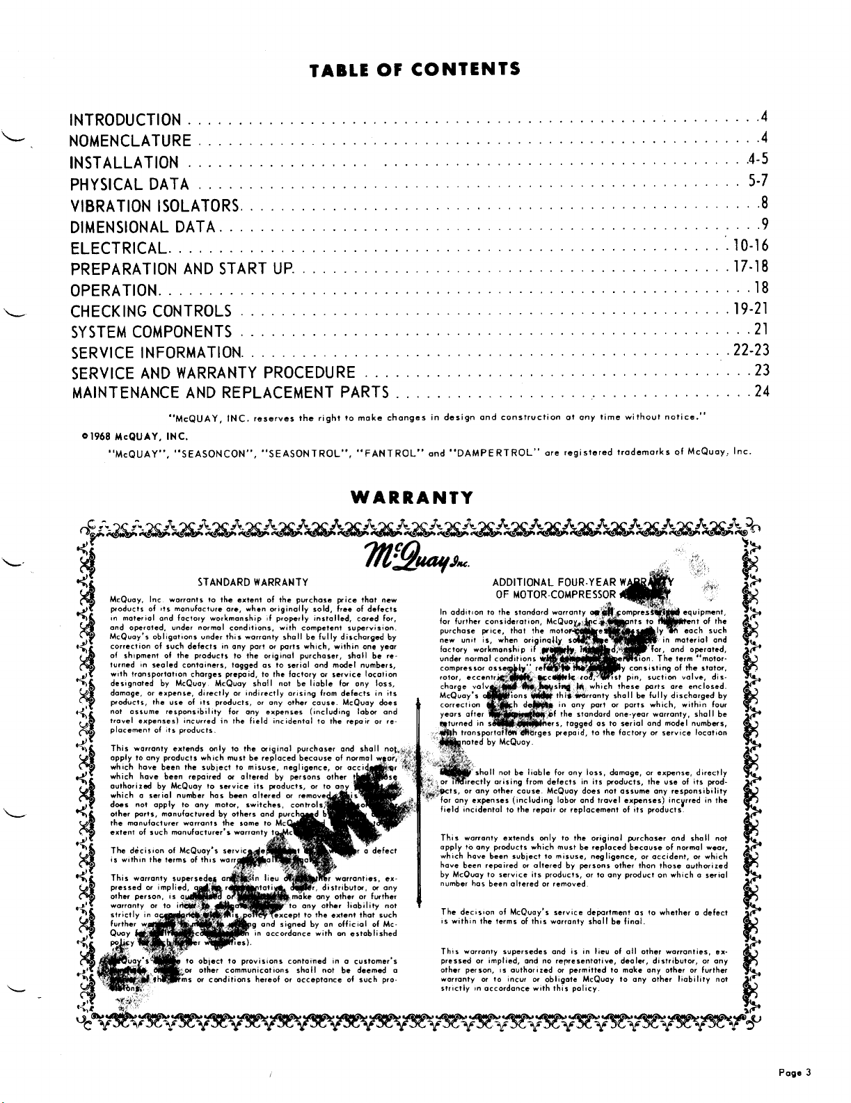
NOMENCLATURE
117
CUB-027s 1
D
1
INSTALLATION
GENERAL Commerical equipment of this type is in-
tended for installation by qualified refrigeration mechanics only. As a condition of the warranty the check,
test, and startup procedure must be performed by such
personnel and properly reported on the form provided.
Failure to do so voids the warranty. Arrangement for
service should be made prior to installation, as it is
not included in the warranty or the catalog price. See
warranty terms on Page 3.
INSPECTION When the equipment is received, all
items should be carefully checked against the bill of
lading to be sure all crates and cartons have been
received. All units should be carefully inspected for
damage when received. Visible or concealed damage
should be reported immediately to the carrier and a
claim
filed fordamage. The electrical nameplate should
be checked to be sure it agrees with the power supply
available.
LOCATION The
ing units are designed for outdoor application. The
evaporator and accessories connected to the unit are
ordinarily installed indoors.
The cabinet is made of heavy reinforced aluminum
panels to give a fairly light but durable unit.
The condensing unit should be located so that all
four sides of the unit have free area for inlet air flow.
The unit should not be located closer than one fan
diameter from a wall or other obstructions. The units
have an
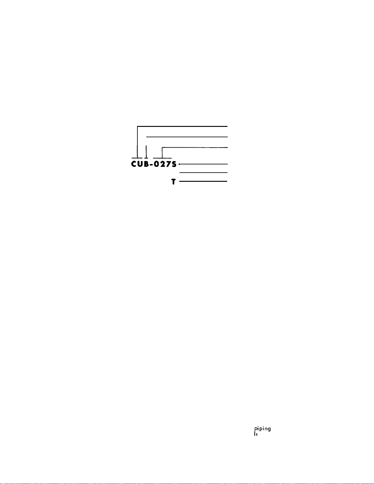
in from the underside of the unit.
ished with suitable holes in the legs and channels for
use by the riggers. See Figure 1, Page 5.
man has free access to the compressor compartment
and to the access panel and the condenser fans and
motors. If the location of the
tion may be transmitted objectionably to the building+
vibration isolators should be used.
upflow
The unit must be mounted level. The unit is furn-
The unit location should be such that the service
McQUAY
condenser air discharge, with air taken
line of air cooled condens-
unit
is such that
vibra-
or(s) (single, dual, or tandem), air cooled condenser
with propeller fans & motors and a completely wired
control panel in a heavy aluminum cabinet. The control panel includes a power terminal block, circuit
breaker protection for all motor phases, starting
tactors,
ready for operations.
SERVICEABILITY The compressor compartment is
accessible from the top and two sides by simply removing panels. Under no condition should any access
panel be blocked or locked in place by mounting parts
on them or running piping through them.
area has generously sized access doors for checking
the fan motors, belts, and drive. On direct drive units
access is through the fan orifice.
enclosure having a
the first section of the line proper.
that vibration from the unit is not transmitted from the
equipment to the bui
joints
or flexible connectors in the lines will be required.
All refrigeration lines must be checked and secured to
prevent wear or vibration at all operating conditions.
and safety and overload controls, wired and
Air Cooled Condensing Unit
Series Designation
Nominal Capacity (Tons)
Single Compressor
Dual Compressors
Tandem Compressor
On the belt driven fan units, the condenser fan motor
The control panel is protected by a weather proof
REFRIGERANT PIPING The refrigerant piping should
be installed according to standard practice and should
follow latest
the motor-compressors are resilient mounted, it is
necessary that a vibration eliminator be installed between the suction connection on the compressor and
There must be sufficient flexibility in the piping so
at the unit are not stressed. Loops, hairpins,
A filter-drier must be installed in the liquid line to
pick up acids, dirt and moisture that may be left in
the system. A moisture indicating sight glass, located
in the liquid line, must also be installed. A suction
line filter is also recommended to prevent grit or dirt
from getting to the compressor.
The unit is furnished with a liquid line shut off
valve located ot the subcooler outlet.
It is urged that dry nitrogen be run through the connecting refrigerant lines during the brazing operation
to prevent oxidation of
joints are not acceptab e.
CONTROL PANEL All operational and refrigerant
safety controls are located in the control panel. Also
note following section on fuses and circuit breakers.
ASHRAE
gasketed
and hinged door.
guide recommendations. In that
Iding,
and so that the brazed
iping
P
interior. Soft soldered
con-
Page
4
Page 5
Page 6
Page 7
Page 8
Page 9

Page 10

ELECTRICAL
ELECTRICAL
CONTROL
CENTER
The McQuay SEASONCON air cooled condensing
unit has a superior electrical control center desi
with safety and reliability as the foremost
tion. It is enclosed in a weathertight cabinet with
hinged access doors and key lock for added protection.
All necessary safety and operating controls are included
and are factory wired in accordance with the
National Electric Code. The control cabinet,
ible from outside the unit, protects all controls from
accidental damage and prevents unauthorized
nel from tampering with them.
A partition separates the
from the storting controls. A dead-front panel covers
the starting controls to protect the operator from any
FIGURE 6
adjustable
cons1
safety controls
ned
.8
era-
access-
person-
exposed terminals or contacts. All refrigeration controls are covered and can be
contacting line voltage.
panels removed to show internal controls and wiring.
It is important to have a qualified electrician service
this panel.
can cause serious damage to equipment and void the
warronty.
WARRANTY: Warranty is voided if wiring is not in
accordonce with specifications. A blown fuse or
ped protector indicates a short, ground or
before replacing fuse or restarting compressor, the
trouble must be found ond corrected.
Unqualified
adjusted
Figure 6 shows dead-front
tampering with the controls
without fear of
trip-
overload -
.13
12
9
SWITCHES-ON/OFF
RELAYS
SWITCHES-RESET
FUSE-CONTROL CIRCUIT
PART WINDING START
(Optional)
CONTACTOR-
FAN MOTORS
1.
THERMOSTAT-
FAN CYCLING
2. OIL PRESSURE CONTROL
(Manual Reset)
3. HIGH PRESSURE
CONTROLS
4. LOW PRESSURE CONTROLS
5. TIME DELAY RELAYCOMPRESSOR SEQUENCING
8
6.
7.
8.
9.
10. TIME DELAY RELAY-
11.
FIELD WIRING
Wiring
with al
Threemain power leads must be connected to the
condensing unit. Table 8, Page 16, gives the recommended lead wire sizes for three conductors in a
raceway.
Maximum supply voltage variation is
plate value. Phase voltage unbalance must not exceed
2%.
The condensing unit is wired to operate on a nonrec
sta
The liquid line solenoid is to be controlled by a return
air or space thermostat for air conditioning duty, or
of the systems should be done in accordance
applicable codes and ordinances.
9
?
10% of name-
clingpumpdown cycle and it is necessary to
ll
I
24 volt liquid line solenoid valves in the system.
in-
10
suitable thermostat for water chilling. For dual compressor units,
valves should be used as shown in Diagram 1, Page 11.
Although there is no specific requirement, interlocking of the evaporator fan motor is recommended so the
condensing unit will not run unless the evaporator fan
motor is running.
locking on auxiliary contact of the evaporator fan
motor starter across terminals 25
Diaaram 3. A sail switch could be wired across the
same
Refer to wiring diagrams provided
specific wiring diagram for each model.
11
12. CONTACTORSCOMPRESSORS
13. CIRCUIT
FAN MOTORS
14. CIRCUIT BREAKERSCOMPRESSORS
15. POWER TERMINAL BLOCK
& POWER CONNECTION
a two-stage thermostat and two solenoid
This can be accomplished by inter-
terminals to accomplish the
BREAKER-
& 26 as shown in
same results.
with units for
Page 10
Page 11

UNLOADERS Cylinder unloading capacity control is
available on all except the
CUB-007S.
Unloading con-
sists of opening a gas by-pass circuit from the cylin-
der head to the low pressure side of the compressor
by means of a solenoid valve. Unloading results when
the solenoid valve coil is energized. The unloading is
controlled by an open-on-rise pressure control switch
in series with the unloader solenoid coil. The pressure
control is
adjustable
in both range and differential.
The pressure control is set at the factory on a nominal basis. Final adjustment must be made in the field
based on the individual system compressor
-
evapora-
tor balance. For nominal settings, refer to Table 15,
Page 21.
FUSES AND CIRCUIT BREAKERS The circuit breakers for the compressor and condenser fan motor
tactors
are located in the control box. In addition,
con-
there are small fuses for the compressor control circuits located in the end of the compressor terminal
box.A fuse in the control box also protects the control
circuit.
Most local electrical codes also require a fused
disconnect switch in the unit supply circuit, located
within easy reach or within sight of the unit.
CONTROL WIRING INFORMATION Temperature controls ore usually separate from the main condensing
unit controls. These controls usually consist of a
liquid line solenoidvalve opened and closed by a room
thermostat. The thermostat can be either low voltage
or line voltage.On a year around system consisting
of cooling and heating, a combination heating and
cooling thermostat is commonly used.
CRANKCASE HEATERS The compressors are equipped
with crankcase heaters. The 15HP and smaller model
compressors have heaters installed externally below
the crankcase. The 20HP and larger model compressors have heaters inserted into the crankcase.
The function of the heater is to keep the temperature
in the crankcase high enough to retard refrigerant from
migrating to the crankcase and condensing in the oil.
When a system is to be started up initially in cold
ombient, the power to the heaters should be turned on
for some time (at least 8 hrs.) before the compressor
system is started.
The crankcase should be up to
about 8OF before the system is started up, to minimize
lubrication problems or liquid slugging of compressor
on startup.
IMPEDANCE RELAY OVERLOAD PROTECTION
order to provide reset of unit in conditioned space or
at the unit, an impedance relay is incorporated into the
control circuit. Basically, this type of control is centered around a relay with a high impedance holding
coil connected in series with the basic relays and
contactors,
but in parallel with the safety automatic
reset control or controls. The impedance relay normally
closed contacts are located in the safety control circuit. A normally open momentary contact reset button
installed at the panel or remotely is connected in para-
llel with the relay normally closed contacts, or relay
coil.
For typical operation, refer to Diagram 2, Pages 12
and 13. Note that coil of impedance relay R4 is in
series with the group of controls Ml, M2, and R2. The
coil is also in parallel with the high pressure control
HP1,
and the normally closed relay contacts R4. In
normal operation, HP1 and R4 are closed and, therefore, there is no voltage across relay coil R4. However, when the system goes out on high head pressure,
control HP1 opens; R4 coil is now in series with the
group of controls Ml, M2 and R2. Although the relay
coil R4 is in series with the group of controls, there
is sufficient voltage across it to open the normally
closed contact R4. When the high pressure control HP1
closes again on reduction in head pressure,
the
normally closed contact R4 is still held open by voltage across coil R4.
It is, therefore, necessary to push reset switch S3
to jumper contact R4 and drop out the impedance relay
so that the system can start. A remote momentary con-
tact reset switch in parallel with
S3
may be installed
for remotely restarting the unit.
Where compressors have external overload protection, both the HPC and the external overload control
circuit is reset by the impedance circuit. Where compressors have internal overload protection, automatic
reset, only the HPC outage is reset by the impedance
circuit.
In
DIAGRAM 1
I0 DIIco**rcI
m.1-)10 >Y) “OLT
‘my: ~~c;~~‘,~‘“‘“”
!
TYPICAL FIELD WIRING
CUB AND AIR HANDLER
NOTES:
(1)
R3 Relay Coil voltage
to be same as motor
voltage
starter
(2) Rl and R2 Relays are
in condensing unit
control center.
(3) All items except
and R2
others.
(4)
_29
terminal strip numbers in condensing
unit control center.
Designates
Relays by
R1
Page 11
Page 12

Page 13

Page 14

Page 15

Page 16

Page 17

EVACUATING AND CHARGING The condensing unit,
as shipped from the factory, has been checked under
normal operating conditions. The unit is shipped with
a holding charge of R-22 refrigerant.
Care should be used to keep the system closed as
long as possible when making the piping connections.
Every precaution must be followed to prevent dirt and
moisture from entering the system. Under no condition
is the unit piping or components of the system to be
exposed to atmospheric moisture. Always cap or seal
all exposed pipe ends or refrigerant tubing during in-
stallotion.
Standard
be followed after piping and pressure testing is completed.
evacuation
and charging procedures should
NORMAL REFRIGERANT CHARGE The condenser
coil has a built-in subcooler. For optimum operation,
the liquid sight glass in the liquid line between the
receiver and subcooler should be substantially free of
bubbles. A completely clear sight glass indicates an
overcharged system.
pected unless the overcharge is sufficient to create
No adverse affect need be ex-
an excessive head pressure caused by appreciable
liquid flooding of a portion of the condenser coil. The
minimum charge at which the unit will operate properly
is with clear sight glass between the filter-drier and
thermostatic expansion valve. Sight glass, filter-drier,
liquid line solenoid, and expansion valve are neces-
sary and must be furnished by others.
-
CHARGING SYSTEMS
erant systems using the SEASONTROL head pressure
control require a substantially larger refrigerant charge
than a standard system designed for summer use only.
The following procedures
TROL head pressure control system are recommended:
A. If the ambient is such that the system is condens-
ing at a temperature of 95F or above, charge the
unit like a standard unit. That is, charge until you
have a clear sight glass with a nominal reserve.
Then add a charge equal to the difference between
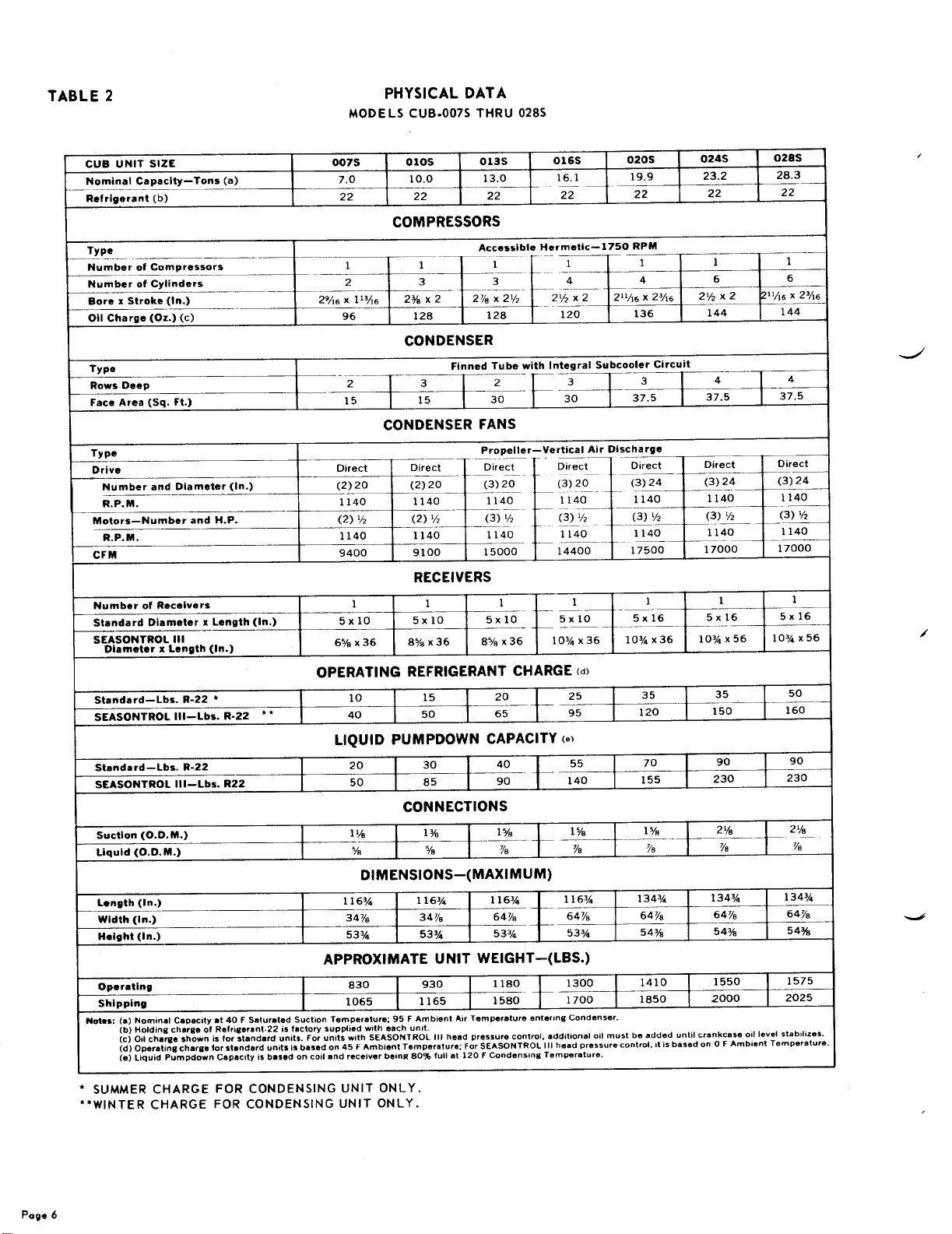
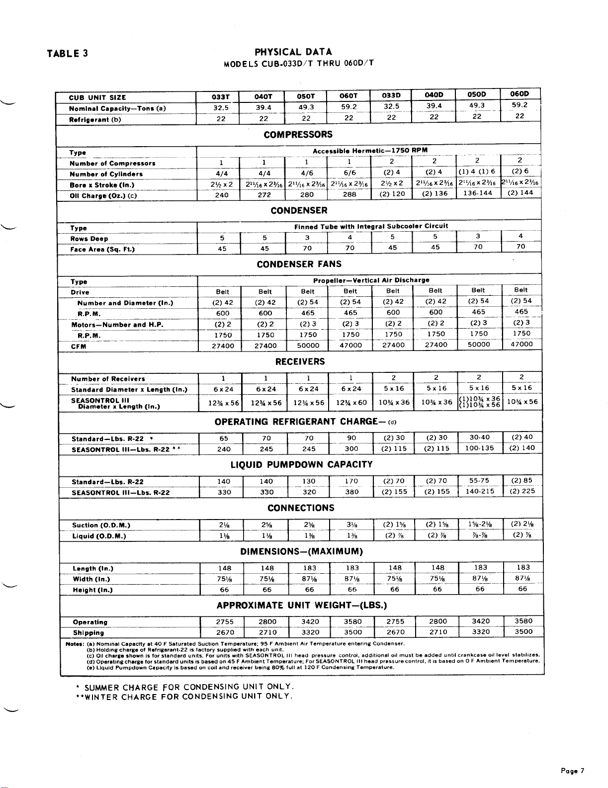
summer and winter charge, as given in Tables 2 &
3, Pages 6 and 7.
WITH SEASONTROL Refrig-
for charging the
SEASON-
\L;hT;
B.
nor;ally’
the specific system.Th
the condenser with cardboard or other material
until the head pressurerises to a pressureof about
225 psig to make sure the SEASONTROL head
pressure control is open and that no refrigerant is
blocked up in the condenser. Then add
until the sight glass clears up with a nominal
reserve. Then add the winter operation charge
which should be equal to the difference between
the required summer charge and winter charge for
the specific unit or section. See Tables 2 & 3,
Pages 6 and 7.
stem is char ed when the ambient is quite
or lower, a d a nominal charge that might
F
be considered a reasonable amount for
B
en cover the inlet side of
refrigerant
OIL CHARGE Because of the rather large refrigerant
charge required in an air cooled condensing unit system, it is usually necessary to put additional oil into
the system. The oil level should be watched carefully
upon initial startup and for some time thereafter.
At the present time, Suniso #3G oil is the only oil
approved by
sors. The oil level should be maintained at a level
about midpoint of the glass bullseye on the compressor body.
Copeland
for the use in these compres-
SETTING LOW PRESSURE CONTROL FOR LOW
AMBIENT START
and cut-in point of the low pressure control depends
upon the lowest ambient in which the air conditioning
system is expected to be used. Inasmuch as both the
condenser and the receiver are
ambient, it is necessary to set the low pressure control at a pressure considerably lower than the pressure
corresponding to the temperature of the lowest ambient
point. Otherwise,the low pressure control will not
cut-in to get the system started; or, in marginal tem-
perature, may cut-in but short-cycle.
Table 10, Page 18, shows the nominal low pressure
control settings for systems using R-22 refrigerant to
insure starting at the given ambient temperatures.
These are nominal settings. Final settings must be
based
on actual checkout of the individual system.
The proper setting of the cut-out
located
in the outside
TABLE 9
REFRIGERANT LINE CAPACITIES FOR REFRIGERANT R-22
(TONS OF REFRIGERATION RESULTING IN A LINE FRICTION DROP PER 100 FT. EQUIV.
PIPE LENGTH CORRESPONDING TO 2F
(AT)
CHANGE IN SATURATION TEMP.)
Page
17
Page 18

TABLE
10
CONTROL SETTING FOR LOW
AMBIENT OPERATION
LOW PRESSURE CONTROL
MINIMUM
OPERATING
AMBIENT
*The
settings are all for singles, duals and #1 tandem
compressor low pressure controls. #2 tandem control must
remain ret at
normal settings.
(F)
+30
+20
+10
0
-10
-20
normal
setting. See Table 15, Page 21, for
CONTROL SETTING
CUT-IN
(PSIG)
50
38 20
28
20
12 2
7 0
*
CUT-OUT
(PSIG)
32
10
5
OPERATION
PERIODIC SERVICE (At end of first week of opera-
tion and once a month thereafter).
A.
Check compressor oil level.’ Oil should
proximately
Compressors are furnished with oil fill plug on the
side of crankcase.
B.
Check liquid sight glass for proper refrigerant
charge.
C.
Check belt tension, and observe condition of belts.
D.
Check condenser coil face for obstruction. If necessary, flush with cold water, brush off, or use
vacuum cleaner.
E.
Make general inspection of entire system for any
unusual sound or condition.
1/2
of the oil level glass. Copelond
WEEK END OR SHORT PERIOD SHUTDOWN
A. Turn off switch
noid valve(s).
B. Wait for system to pump down.
C. Turn off shut-off switch
fan motor.
closing evoporator liquid line sole-
S1.
Turn off evoporator
START UP FOLLOWING WEEK END SHUTDOWN
A. Turn on evaporator fan motor.
B. Turn system switch
C. Turn to “on”
valve(s). Observe operation for several minutes,
noting any unusual sounds, or unusual cycling of
compressors.
EXTENDED SHUTDOWN
Close the liquid line shut-off valve.
A.
Wait for the compressor to pump down until it
B.
shuts off on low pressure control.
C.
Turn off the power to the compressors, condenser
fan motors, cronkcose heaters, and evaporator fan
motor.
D.
Close the suction and discharge shut-off
E.
all
Tag
ogainst starting up the compressor before properly
re-opening the shut-off volves.
opened disconnect switches warning
S1
to “on” position.
switch opening liquid line solenoid
START UP AFTER EXTENDED SHUTDOWN
A.
Inspect all equipment.
B.
Check face of condenser coil for paper or other
obstruction that might be lodged on the
Open the suction and discharge service valves.
C.
D.
Turn on the electric power to the system.
Open the liquid line shut-off valve or valves.
Start the air handler or chilled water pump.
FE:
Check crankcase heater & crankcase warmth.
G.
cover
valves.
surface.
ap-
TABLE 11
WEIGHT OF REFRIGERANT (R-22) IN
COPPER LINES*
LBS. PER 100 LINEAL FEET
*Type L copper tubing.
H. Start the unit by turning on system switches.
J. After the unit has run for severol minutes, check
the oil level in the crankcase, and observe flow
through the refrigerant sight glass for sufficient
refrigeront charge.
SEASONTROL
stalled system,
back into the condenser coil, thereby reducing the effective condenser surface available for condensing.
The SEASONTROL head pressure control system is
an improved method of head pressure control incorporating two modulating valves. Its operotion is independent of difference of elevation between the condenser
and receiver.
The main, or liquid line, valve is normally closed,
and opens on
valve IS locate in the liquid line between the conden-
ser and receiver. The gas, or bypass, volve is normally
open ond closes on pressure rise. This valve is located in the line between the hot gos header and the
liquid line section between the liquid SEASONTROL
head pressure control valve and the receiver. See
Figure 9, Page 20.
The system operates
up, the bypass valve is normally open and the moin or
liquid valve is closed. Hot gas moves from the compressor, part going into the condenser, and port going
through the byposs circuit through the open volve ond
into the receiver. The bypass gas goes directly into
the receiver to maintain or build up pressure in the
receiver as liquid leaves. As the compressor contin-
ues to run, hot gos condenses in the condenser and
roises the liquid level since the main valve on the
leaving side of the condenser is still closed. As the
liquid level in the condenser rises, the condensing
capacity of the condenser
the head pressure rises. The bypass gas maintains or
raises the pressure in the receiver. As the pressure
in the condenser rises to the control point of the
valve, the liquid valve starts moduloting towards the
open position, permitting liquid to leove the conden-
ser and flow into the receiver. At the same time, the
bypass valve starts modulatin
position, limiting the hot gas low into the receiver.
The modulation of the two valves maintain the proper
iiquid level in the condenser to mointoin proper head
Yessure.
rquid fromthe condenser to near saturation tempera-
ture.
head pressure control Is o factory in-
based on liquid refrigerant flooding
Bressure,
The bypass gos also warms up the cold
rise in the condenser. This
OS follows: On system start
decreases
and, OS a result,
towards the closed
9
Page
18
Page 19

CHECKING
CONTROLS
FANTROL head pressure control is an automatic
winter control method and will maintain a condensing
pressure within reasonable limits by cycling one fan
on a two fan unit, or two fans in sequence on a three
fan unit in response to outsideair temperature entering
the condensing coil.
One of the more obvious advantages of multiple fon
condensers over sin
expensive woy in w
may be achieved. On
le
fan units is the simple and in-
it*
rch
controlled
a
two fan unit, stopping one fan
capacity
reduction
reduces the condenser capacity to approximately 55%
of full rating. On a three fan unit, stopping two fans
reduces the condenser capacity to approximately 40%
of full roting.
DIAGRAM 4
FANTROL head pressure control
SYSTEM WI RING
NOTE: On CUB
TABLE 13
0075-0285
employed and only two wires
single
phase
condenser fan motors are
are
broken by the thermostat.
FANTROL THERMOSTAT SETTING (F)
Fan motors are internal inherent overload protected,
and are started by a single contactor, with the individual fan motors cycled by use of two
thermostats. See Diagram 4,
Page
19.
pole,
heovy duty
Thermostats are nominally set to maintain condensing temperatures between a high of 120F and a
low
of about 80F. The final setting of the thermostats
varies with system design conditions. The settings
shown on Table 13, Page 19, will ordinarily give satisfactory operation.
Where operation at ambients below the range shown
on Table 12, Page 19, are required, Seasontrol or
Dampertrol may be added.
TABLE 12
FANTROL head pressure control (Std)
(Ambient Low Limit)
“NlT
CUB
!K
zx
0135
0166
ii%
0285
OJ9T
go; :: 28
033D
2;
PData
based on:
Capmtv
_
50
66%
step %
MinimumCondensing
UNIT WITH STANDARD
CAPACIYY
REDUCTION
MINIMUM
CAPACITY
STEP
g
6%
loo
:x
5
Tamp.
“zN;?E\?
TEMP.
m*
:t
21
;;
10
fZ :8
3”:
zt
100
1
9OF
WITH ADDITIONAL
CAPACITY REDUCTION
MINIMUM
c:Tp:pe’;ry
3%
33%
s:
3:Os
25
fl
33%
1
67.60
1
BOF
z%F
TEMP.
42
35
56
48 :d
T
39
1
50.20
1
70
(Fy
F
TWO FAN UNITS
THERMOSTAT
CUT-IN
65
CUT-OUT
I
55
THERMOSTAT
CUT-IN
65
DAMPERTROL head pressure control The discharge
side face and bypass dampers ore controlled
by
a pressure actuated operator connected to the high pressure
side of the refrigeration system. As pressure increas-
es in the system, the operator opens the face damper
blades and closes the two bypass blades to prevent
recirculation of air around the fan. The damper operator starts moving at 175 psig (from closed position)
and is fully extended at 250
PSIG
(fully opened posi-
tion).
TABLE 14
DAMPERTROL head pressure control (Opt)
(Ambient Low Limit)
Data
CUB
XK
based
on:
Capacity
UNIT
WITH
CAPACITY REDUCTION
MINIMUM
Step %
STANDARD
UNIT WITH
CAPACITY REDUCTION
ADDITIDNAL
THREE FAN UNITS
#1
CUT-OUT
I
55
THERMOSTAT
CUT-IN
I
50
CUT-OUT
FIGURE 7
DAMPERTROL C head pressure control
DAMPERTROL C IN OPEN POSITION
DAMPERTROL C IN BYPASS POSITION
DAMPERTROL C head pressure control sections.
Show air flow in
(winter start) position. For operation to
open
(normal) position and closed
-2OF
#2
40
ambient.
Page
19
Page 20

SEASONTROL head pressure control VALVE CHECK-
ING AND SETTING
control valves are factory set and checked to maintain
a minimum head pressure equivalent to 90F condensing.
The valves have a nominal 15
range between fully open and fully closed positions.
Typical settings for Refrigerant-22 use is to have the
valves modulate between 160 and 175 PSIG. This will
maintain a nominal 90F condensing.
Referring to Figure 8, Page 20, it is to be noted that
on pressure Increase on the system, the pressure
tend to compress the bellows and the valve stroke
will be u
This
or toward the adjustment end of the valve.
r
app
res to both the liquid and gas valves. The
239 series, or liquid valves, open on pressure rise.
The 237 series, or gas bypass valves, close on pressure rise. The valve travel is a nominal one tenth inch
for all models.
A
S indicated in the diagrams, the adjustment of the
nut in a clockwise direction will increase the modula-
ting pressure point.
similar instrument inserted into the nut slot may be
used for making the
The modulating pressure point and range may be
checked as follows:
A. Make up a “depth gauge” for inserting through the
FIGURE 8
The SEASONTROL head pressure
PSIG
modulating
will
A wide bladed screwdriver or
adjustment.
SEASONTROL head pressure control
TYPE 239 LIQUID VALVE
8A. SECTIONAL VIEW
adjusting
nut opening and long enough to hit the
bottom of the bellows section as indicated in
Figure
8B,
Page 20. A piece of insulated wire, 8
to 12 auge, is a simple and convenient material
from w
rch
to make a gauge. Insert a piece of the
1.
wire into the valve as shown in the diagram. Trim
off insulation, for about one inch of the end to be
inserted, and at a point just above the top of the
valve at the other end. When in use hold the gauge
down lightly against the bellows and sight along
the top of valve.
A high side gauge should be connected to a line
B.
so it can be brought to the valve area unless a
second person is available to call out head pres-
sure readings while valve observations are made.
Start up the unit and note pressures at which valve
C.
bellows rise.
We assume
that the pressure was low
enough at start up so that the bellows is in the
down position. The test may also be done in re-
verse by running the system u to a high head
B
making observa-
pressure,
stopping the unit,
an
tions at what pressure the valve changes position.
The valves should be set so that the movement of
D.
both valves is through the same pressure range.
Be sure system has sufficient refrigerant before
E.
making any change in valve adiustment.
8B.
CONTROL SETTING
FIGURE 9
t
LIQUID
OUTLET
HOT GAS HEADER
LIQUID HEADER
LIQUID LINE
BY PASS LINE
ADJUSTING NUT
CONTROL SPRING
VALVE SEAT
SEASONTROL III head pressure
For operation to -20F ombient.
w
. .
..I-~“-
-------
ED
l/10”
TRAVEL
FEELER GAUGE INSE
RTED
LIQUID VALVE
RECEIVER
RELIEF VA
PURGE VALVE
\GAS
SUBCOOLER SECTION
VALVE
Page 21

Page 22

Page 23

Page 24

MAINTENANCE
GENERAL
MOTOR
A. The air cooled condenser section requires a mini- A.
mum of maintenance. All that is required is to
lubricate the fan shaft bearings, motor bearings,
and occasionally clean the surface of the coil.
During the initial break-in period, it is advisable
to check the belt tension after the first 48 hours of
operation. Usually, by this time, the belts have
acquired their permanent stretch, and further ad-
‘ustments should not be necessary. It is advisable,
/l
owever,
intervals and, if necessary, make any
B. The fan shaft bearings do not require lubrication
at the time the unit is out into service. The fan
shaft bearings should be greased once a year using
STANDARD OIL COMPANY
Lithium Grease. DO NOT OVERLUBRICATE. The
C. The coil will require a periodic cleaning and this
can be accomplished by a brush, vacuum cleaner
or a pressurized air stream.
to recheck the belt tension at 3 month
adjustments.
Multi-Purpose
All motors are ball bearing, pre-lubricated and do
not require the addition of grease at the time of in-
stallation. Periodically, the ball bearings should
be cleaned and the grease renewed, to gain the
ultimate in service from the motor bearings.
Extreme care must be exercised to prevent foreign
B.
matter from entering the ball bearings. It is also
Important to avoid
clean mineral grease having the following characteristics should be used. Consistency: a little
stiffer than that of Vaseline, maintained over the
operating temperature range; melting point preferably over 150C (302 F); freedom from separation
of oil and soap under operating and storage condi-
tions, and freedom from abrasive matter, acid alkali
and moisture.
Specific greasing instructions are to be found on
C.
the tag attached to the motor and should be genera I ly fol lowed.
overgreasing
Only a
high
grade
REPLACEMENT PARTS
Replacement service parts can be ordered throu hJinvolved. Replacement parts for the motor-compressor
your nearest
complete description of service port, part number if
known, plus complete serial and model number of unit
McQUAY
representative. Always
prove
e
assembly can be procured direct from your nearest
franchised
saler.
Copeland
Refrigeration Corporation Whole-
INC.*
13600 INDUSTRIAL PARK BLVD., P.O. BOX 1551. MINNEAPOLIS, MINNESOTA 55440
PHONE:
545-2892
l AREA CODE: 612
@
 Loading...