

Page 1
Installation and Maintenance Manual IM-799
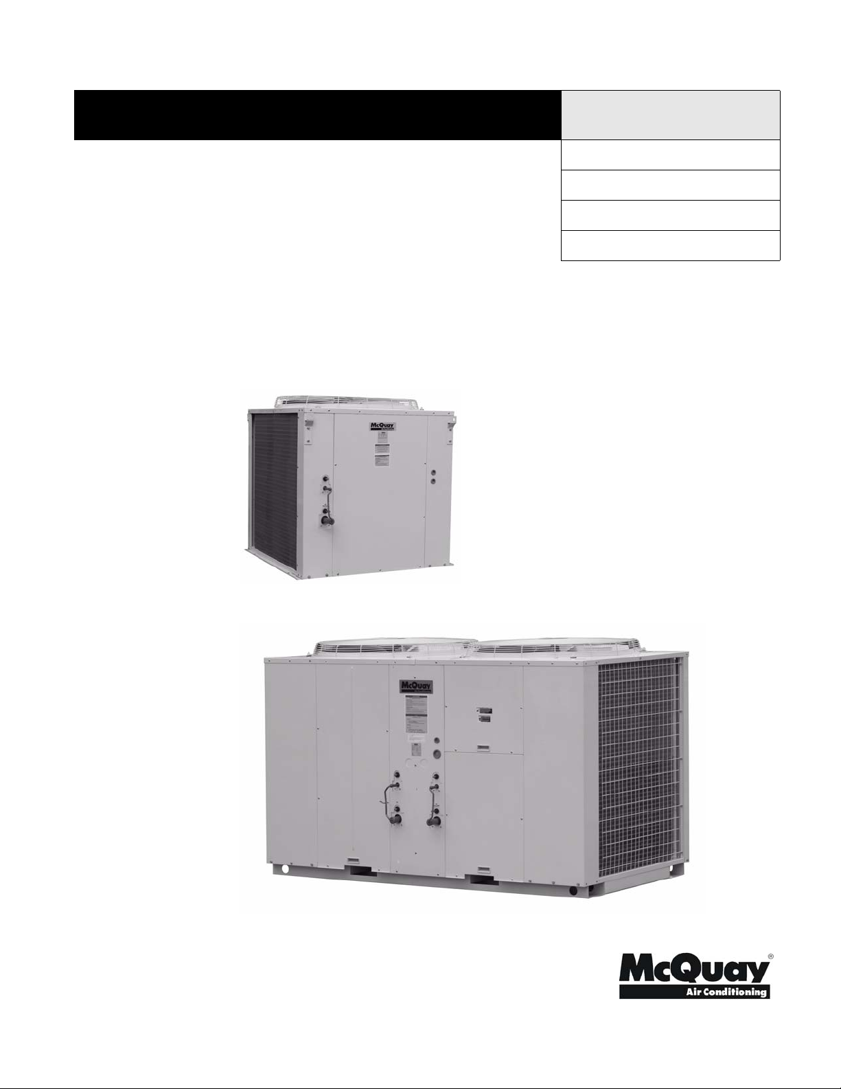
Air-Cooled Split Systems
Models ACU 075 to 300
75 to 300 MBH
60 Hz, R-22 Refrigerant
ACU 075 to 150
Group: Unitary
Part Number: IM-799
Date: August 2005
Supersedes: July 2004
ACU 200 to 300
© 2004 McQuay International
IM-799 Page 1
Page 2
Table of Contents
Introduction . . . . . . . . . . . . . . . . . . . . . . . . . . . . . . . . . . 3
General Description . . . . . . . . . . . . . . . . . . . . . . . . . . . . . 3
Inspection . . . . . . . . . . . . . . . . . . . . . . . . . . . . . . . . . . . . . 3
Installation . . . . . . . . . . . . . . . . . . . . . . . . . . . . . . . . . . . . 3
Component Location. . . . . . . . . . . . . . . . . . . . . . . . . . . . . 4
Handling . . . . . . . . . . . . . . . . . . . . . . . . . . . . . . . . . . . . . . 5
Location . . . . . . . . . . . . . . . . . . . . . . . . . . . . . . . . . . . . . . 5
Unit Placement . . . . . . . . . . . . . . . . . . . . . . . . . . . . . . . 5
Service Access . . . . . . . . . . . . . . . . . . . . . . . . . . . . . . . . . 5
Vibration Isolators . . . . . . . . . . . . . . . . . . . . . . . . . . . . . . 5
Dimensions . . . . . . . . . . . . . . . . . . . . . . . . . . . . . . . . . . . . 6
Installation Instructions . . . . . . . . . . . . . . . . . . . . . . . . . 7
Location For Installation of Condensing Units . . . . . . . . 7
Field Piping . . . . . . . . . . . . . . . . . . . . . . . . . . . . . . . . . . . 7
Sound Isolation . . . . . . . . . . . . . . . . . . . . . . . . . . . . . . . 8
Vacuuming and Charging . . . . . . . . . . . . . . . . . . . . . . . . 8
Vacuuming . . . . . . . . . . . . . . . . . . . . . . . . . . . . . . . . . . 8
Charging. . . . . . . . . . . . . . . . . . . . . . . . . . . . . . . . . . . . . 8
Field Charging Precautions . . . . . . . . . . . . . . . . . . . . . . . 8
Equipment . . . . . . . . . . . . . . . . . . . . . . . . . . . . . . . . . . . 9
Charging Hoses . . . . . . . . . . . . . . . . . . . . . . . . . . . . . . . 9
Typical Service Valves on ACU Units . . . . . . . . . . . . . 9
How Much Refrigerant? . . . . . . . . . . . . . . . . . . . . . . . . . 9
Charging Procedures - Single Phase Compressor . . . . 10
Piping Works and Flaring Technique . . . . . . . . . . . . . 11
Special Precautions When Mounting TXV Bulb . . . . . 11
Refrigerant Piping . . . . . . . . . . . . . . . . . . . . . . . . . . . . . . 11
Introduction . . . . . . . . . . . . . . . . . . . . . . . . . . . . . . . . . 11
Suction Lines . . . . . . . . . . . . . . . . . . . . . . . . . . . . . . . . 11
Underground Refrigerant Lines . . . . . . . . . . . . . . . . . . 12
Long Vertical Riser Installation . . . . . . . . . . . . . . . . . . 12
Liquid Lines . . . . . . . . . . . . . . . . . . . . . . . . . . . . . . . . . 13
Physical Data . . . . . . . . . . . . . . . . . . . . . . . . . . . . . . . . . 14
Wiring Diagram . . . . . . . . . . . . . . . . . . . . . . . . . . . . . . 15
Start-up and Shutdown . . . . . . . . . . . . . . . . . . . . . . . . 18
Pre Start-up . . . . . . . . . . . . . . . . . . . . . . . . . . . . . . . . . . . 18
Start-up . . . . . . . . . . . . . . . . . . . . . . . . . . . . . . . . . . . . . . 18
System Maintenance . . . . . . . . . . . . . . . . . . . . . . . . . . . 19
General . . . . . . . . . . . . . . . . . . . . . . . . . . . . . . . . . . . . . . 19
Lubrication . . . . . . . . . . . . . . . . . . . . . . . . . . . . . . . . . . . 19
Electrical Terminals . . . . . . . . . . . . . . . . . . . . . . . . . . . . 19
Condensers . . . . . . . . . . . . . . . . . . . . . . . . . . . . . . . . . . . 19
Refrigerant Sight Glass . . . . . . . . . . . . . . . . . . . . . . . . . . 19
Troubleshooting . . . . . . . . . . . . . . . . . . . . . . . . . . . . . . . 19
..................................................................................................................................................................................................................
Manufactured in an ISO certified facility.
"McQuay" is a registered trademark of McQuay International.
© 2004 McQuay International
"Illustrations and information cover the McQuay International products at the time of publication and we reserve the right to make changes in
Page 2 IM-799
design and construction at any time without notice."
Page 3
INTRODUCTION
General Description
McQuay air-cooled condensing units are complete, self-contained automatic refrigerating units. Every unit is completely
assembled, factory wired, and tested. Each unit consists of air-
cooled condensers, Copeland Compliant Scroll
compressor, and internal refrigerant piping, ready to be piped
to a field-supplied evaporator and liquid line accessories.
The electrical control center includes all equipment protection
and operating controls necessary for automatic operation
except for the staging control for the steps of capacity in the
unit. Condenser fan motors are three-phase and started by their
own contactors with inherent overload protection. The compressor has internal line breakage motor protection for inherent
thermal overload protection, except Model ACU 300 which
has solid-state motor protection.
®
hermetic
Receiving Inspection
McQuay products are carefully inspected prior to shipment
and the carrier has assumed responsibility for loss or damage
upon acceptance of the shipment.
Upon receiving your shipment, check all items carefully
against the Bill of Lading. Inspect the unit and/or accessories
for shipping damage as soon as they are received. Immediately file claims for loss or damage, either shipping or concealed, with the shipping company.
Check the unit nameplate to verify the model number and electrical characteristics are correct. In the event an incorrect unit
is shipped, it must be returned to the supplier and must NOT
be installed. The manufacturer disclaims all responsibility for
the installation of incorrectly shipped units.
Important Message to the Installer
This equipment is to be installed by an experienced installation
company and fully trained personnel. Carefully read all
instructions and take into account any special considerations
prior to installing the unit. Give this manual to the owner and
explain its provisions.
Important Message to the Owner
Read these instructions carefully and keep them near the product for future reference. Although these instructions are
addressed primarily to the installer, useful maintenance information is included. Have the installer acquaint you with the
operation of the product and periodic maintenance requirements.
Recognize Safety Symbols, Words, and
Labels
The following symbols and labels are used throughout this
manual to indicate immediate or potential hazards. It is the
owner's and installer's responsibility to read and comply with
all safety information and instructions accompanying these
symbols. Failure to heed safety information increases the risk
of property damage and/or product damage, serious personal
injury or death. Improper installation, operation or maintenance can void the warranty.
DANGER
Immediate hazards which WILL result in property
damage, product damage, severe personal injury and/
or death.
Codes and Regulations
This product is designed and manufactured to permit installation in accordance with National Codes. System design
should, where applicable, follow information presented in
accepted industry guides such as the ASHRAE Handbooks. It
is the installer' s responsibility to install the product in accordance with National Codes and/or prevailing local codes and
regulations. The manufacturer disclaims all responsibility for
equipment installed in violation of any code or regulations.
IMPORTANT
The United States Environmental Protection Agency
(EPA) regulations cover introduction and disposal of
refrigerants in this unit. Failure to follow those
regulations can harm the environment and lead to
substantial fines. Because regulations can change, a
certified technician should perform any work done on
this unit. If you have any questions, please contact the
local office of the EPA.
WARNING
Hazards or unsafe practice CAN result in property
damage, product damage, sever personal injury and/or
death.
CAUTION
Hazards or unsafe practices which CAN result in
property damage, product damage, and/or personal
injury.
Replacement Parts
Replacement parts can be obtained by contacting McQuay at
1
-800-37-PARTS. When contacting McQuay for service or
replacement parts, refer to the model number and serial number of the unit as stamped on the nameplate attached to the
unit.
General Warning
WARNING
Sharp edges and coil surfaces can cause personal
injury. Wear protective gear and avoid contact with
them.
IM-799 Page 3
Page 4
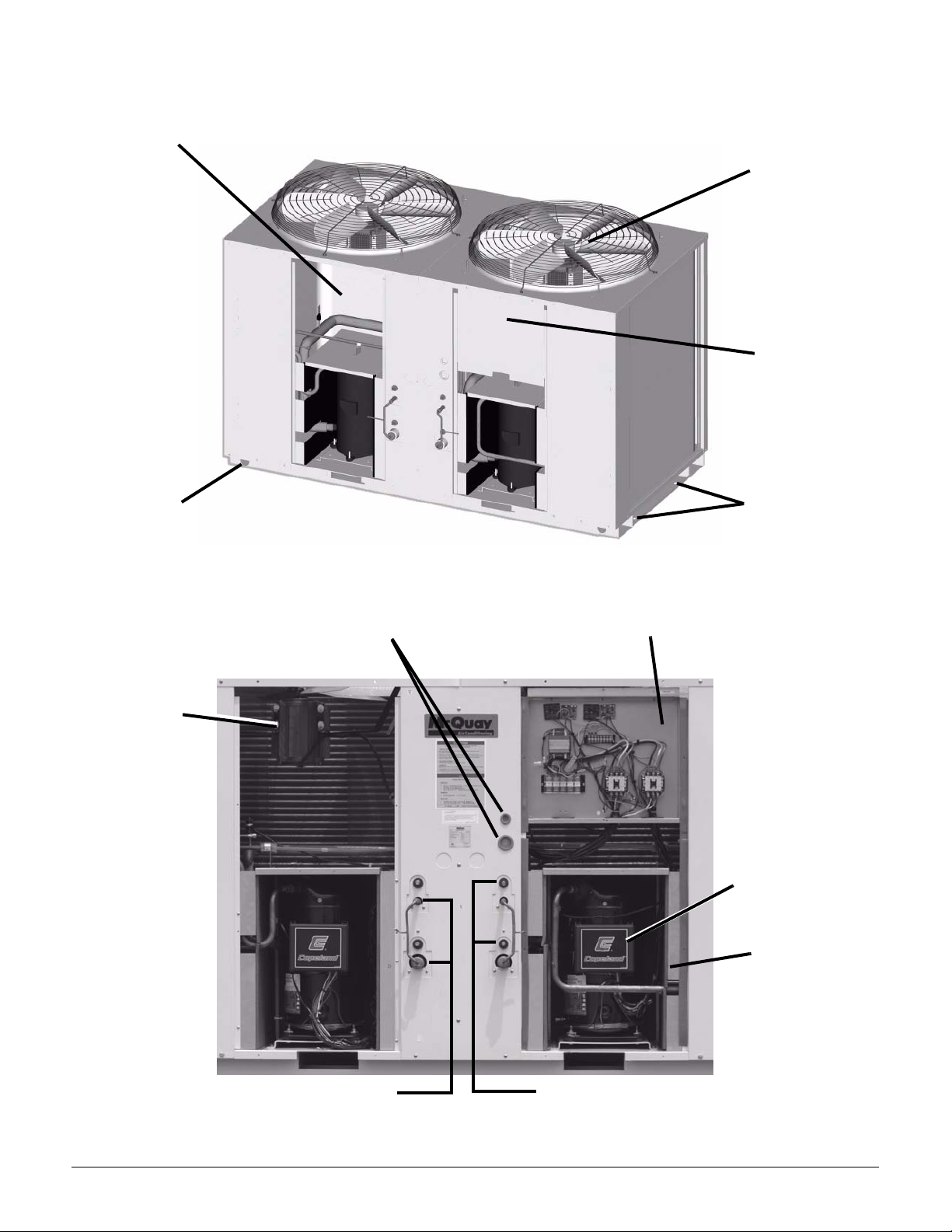
Component Location
Condenser Fan and Motor
Access (Access Panel
Removed)
Lifting Holes
(units are skid
mounted)
Direct Drive
Condenser
Fans
Control Box
Access Panel
Factory Provided
Holes For
Optional Spring
Vibration Isolation
Condenser Fan
Motor
Power and Control Connection
Knock Outs
Control Box
Compressor Motor
Protector
Compressor
Access
Extended Liquid and Suction Lines
For Easy Connection
Page 4 IM-799
Extended High and Low Pressure
Schrader Connections
Page 5
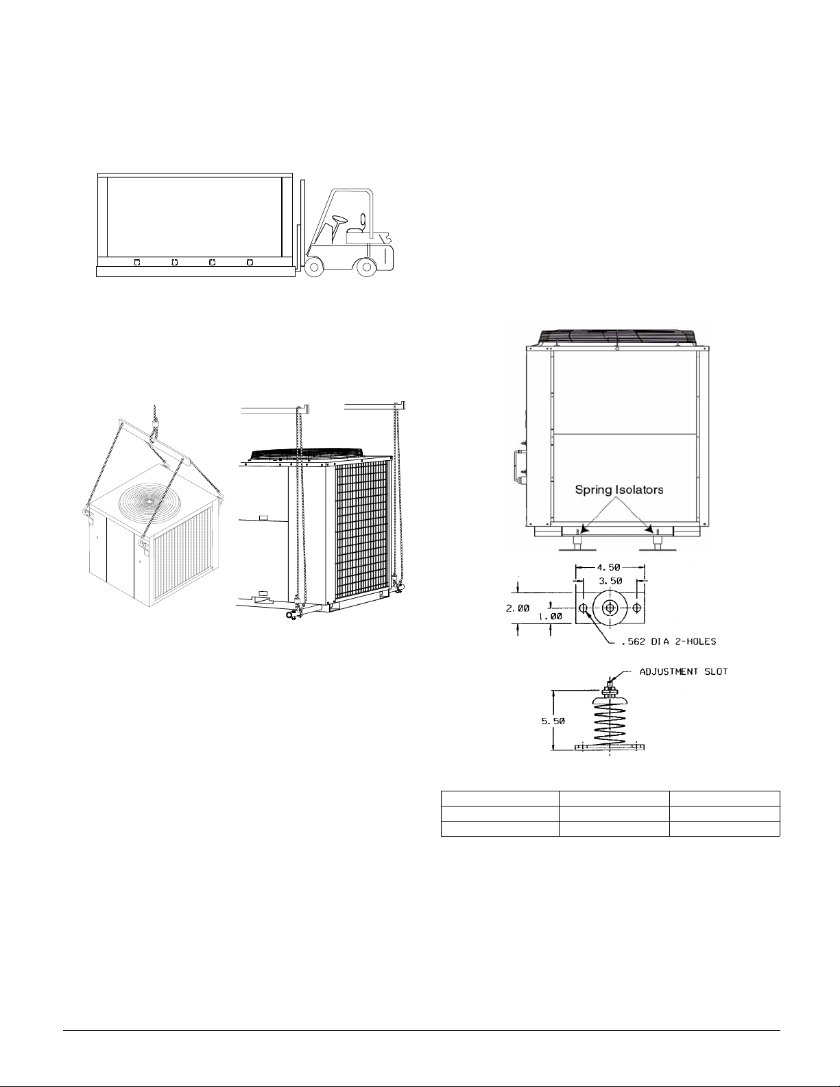
Handling
Be careful to avoid rough handling of the unit. Do not push or
pull the unit from anything other than the shipping skid supplied with the unit to avoid damage to the sheet-metal cabinet
and end frame (see Figure 1).
Figure 1. Suggested Pushing Arrangement
Lifting instructions vary for single circuit (Models 075 to 150)
and dual circuit (Models 200 to 300) units. Models 200 to 300
require spreader bars to help prevent cabinet damage (Figure
2).
Figure 2. Suggested Lifting Arrangement
Models 075 to 150 Models 200 to 300
The fan deck with the condenser fans and motors can be
removed from the top of the unit.
Vibration Isolators
Vibration isolators are recommended for all roof-mounted
installations, or when vibration transmission is a consideration.
Initially, the unit should be on shims or blocks at the listed free
height. When all piping, wiring, flushing, charging, etc. is
completed, adjust the springs upward to loosen the blocks or
shims so they can be removed.
A rubber anti-skid pad is part of the isolator. Installation of
spring isolators requires flexible piping connections and at
least three feet of flexible conduit to avoid straining the piping
and transmitting vibration and noise.
Figure 3. McQuay Spring Isolator Option
Location
Unit Placement
ACU units are for outdoor applications and can be mounted on
a roof or at ground level. Set units on a solid and level foundation. For roof-mounted applications, install the unit on a steel
channel or I-beam frame to support the unit above the roof. For
ground level applications, install the unit on a substantial base
that will not settle. A one-piece concrete slab with footings
extended below the frost line is recommended. Be sure the
foundation is level (within 1/2" [13 mm] over its length and
width). The foundation must support the operating weights
listed in the Physical Data Table on page 14.
Since its operation is affected by wind, the unit should be
located so that the Control Box is perpendicular to the prevailing wind. If this is not practical, field fabricated wind deflectors may be required.
Service Access
Each end of the unit must be accessible after installation for
periodic service. Motor protector controls are on the compressor. Most operating, equipment protection, and starting controls are located in the unit control box. (See page 7 for
details.)
ACU Model Spring Weight Color
075D to 150D (4) 175 lb. Red
200D to 300D (4) 600 lb. Orange
Notes:
1.5.50" free height
2.300 lb./in. mounting construction
3.Base: 2.0" x 4.50" with two (2).562 mtg holes at 3.5 c/c
4.Includes adjustable leveling bolt with slot and.50 locking nut, acoustical
non-skid neoprene pad.
IM-799 Page 5
Page 6
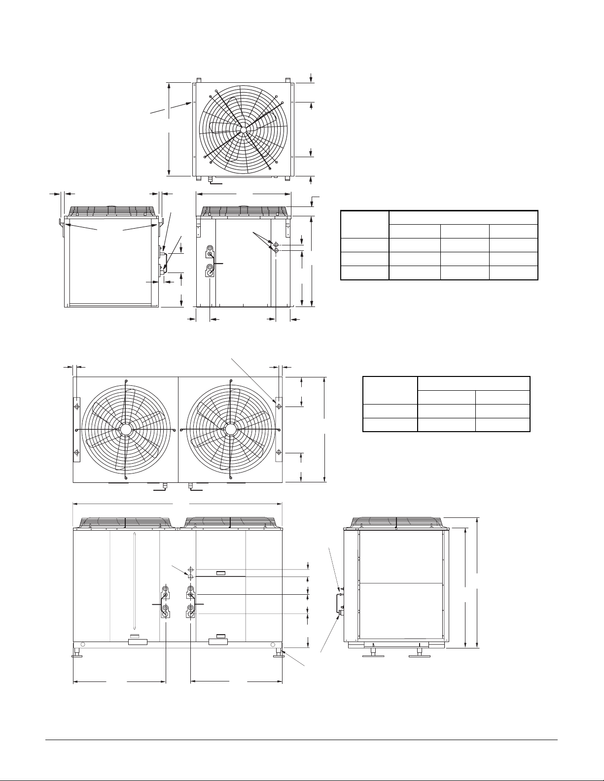
Dimensions
.7
H
Figure 4. ACU 075D to 150D Dimensions (all dimensions in inches)
0.6" Diameter
Mounting Holes
W
7.9
7.9
1.4
1.4
W
Liquid
Lifting
Brackets
Suction
Power
Entry
2.4
7.9
2.0
22.9
A
5.7
5.9
Figure 5. ACU 200D to 300D Dimensions (all dimensions in inches)
0.8" Diameter Mounting Holes
1.6
1.6
12.8
12.8
3
Dimension
(inches)
H
H
W
A
Liquid, suction and hot gas connection sizes are found in Table 3 ACU 075 to ACU 300 Physical Data.
Hot gas bypass connections are inside the cabinet. A 2" knock out is
provided.
075D-100D 125D 150D
37.2 37.2 41.2
38.6 42.6 42.6
13.8 13.9 13.9
Dimension
(inches)
H
45.6
A
Liquid, suction and hot gas connection sizes are found in
Table 3 - ACU 075 to ACU 300 Physical Data.
Hot gas bypass connections are inside the cabinet. A pair
of 2" knock outs are provided.
Model Size
Model Size
200D-250D 300D
48.3 56.4
44.0 52.1
90.2
Liquid
Power
Entry
3.1
7.5
A
7.9
15.4
39.539.5
Suction
Spring Isolator
Page 6 IM-799
Page 7

Installation Instructions
S
P
G
Location For Installation of Condensing
Units
As condensing temperature rises, evaporating temperature
rises and cooling capacity drops. In order to achieve maximum
cooling capacity, the selected location should fulfill the following requirements
A. Sufficient clearance must be provided for proper operation,
service and maintenance. To avoid short circuiting condenser air, the minimum distance between adjacent AHU
units is 40 inches. Do not install a unit above another.:
AIR DISCHARGE
C
SPACE
A
ERVICE
A
ANEL
Dimension Minimum Clearance
A 24”
B 42”
C 59”
B
B
C. Must be well ventilated so that the unit can draw and dis-
tribute plenty of air, which helps lower the condensing temperature.
D. Must be capable of bearing the weight of the unit and iso-
lating noise and vibration.
E. Should be protected from direct sunlight. If necessary, use
an awning for shade.
F. Avoid annoying neighbors with the hot air discharge and
operating sound level.
G. Must not be susceptible to dust or oil mist.
CAUTION
If the condensing unit is operated in an atmosphere
containing oils (including machine oils), salt (coastal
area), sulphide gas (near hot spring, oil refinery plant),
such substances can cause failure of the unit.
Sound Isolation
The ultra-low sound levels for the ACU condensing units is
sufficient for most applications. However, there will be applications where sound generation can be an issue. The most
effective isolation method is to locate the unit away from
sound sensitive areas. Avoid locations beneath windows or
between structures where normal operating sounds can be
objectionable. Reduce structurally transmitted sound by isolating refrigerant lines, electrical conduit and the unit itself. Use
wall sleeves and rubber isolated piping hangers to reduce
transmission of refrigerant flow noise into occupied spaces.
Use flexible electrical conduit to isolate sound through electrical conduit. Spring isolators are effective in reducing the low
amplitude sound generated by scroll compressors and for unit
isolation in sound sensitive areas.
B. Avoid obstructing airflow into or out of the unit. Remove
obstacles that block air intake or discharge.
OBSTACLE BLOCKING
AIR OUTLET
Field Piping
For satisfactory operation and performance, note the following for the field piping arrangements of the complete refrigerant cycle:
A. Liquid loops or oil traps must be provided according to the
position of the outdoor and the indoor units (depending on
whether the indoor unit is above or below the outdoor unit).
OBSTACLE BLOCKIN
AIR INLET
B. Provide the field supplied expansion valve as close to the
indoor unit (evaporator) as possible.
C. Field supplied sight glass and filter drier must be assembled
and mounted next to the expansion valve.
IM-799 Page 7
Page 8

Maximum Pipe Length and Maximum Number of
Bends
When piping is too long, the required refrigerant quantity
increases and both the capacity and reliability decrease. As the
number of bends increase, system piping resistance to the
refrigerant flow increases, which lowers the cooling capacity
and the may cause compressor failure. If the height difference
between the evaporator and the condenser is excessive, the
cooling capacity drops, the lubricating oil return is diminished
and compressor efficiency is adversely affected.
Always choose the shortest piping path and follow the recommendations shown Figures 6 and 7:
Maximum Elevation Maximum Length
Maximum Number
of Bends
Figure 7. Maximum Total Piping
OUTDOOR UNIT
T
H
G
I
E
H
N
O
I
T
A
V
E
L
E
M
U
M
I
X
A
M
G
N
I
P
I
P
L
A
'
T
5
1
O
1
T
M
U
M
I
X
A
M
INDOOR
UNIT
65’ 115’ 8
CAUTION
1. Warranty will be revoked if the height, length
and/or the number of bends of the refrigerant
piping system installed is beyond the limits set
out above.
2. Bends must be carefully made to avoid crush-
ing the pipe. Use a pipe bender.
Figure 6. Maximum Piping Elevation)
T
H
G
I
E
H
N
O
I
T
A
V
E
L
OUTDOOR UNIT
E
M
U
M
I
X
A
M
Condensing Unit Below Coil
N
O
I
T
A
V
E
L
E
G
'
N
5
I
6
P
I
P
M
U
M
I
X
A
M
INDOOR
UNIT
INDOOR
UNIT
Condensing Unit Above Coil
Vacuuming and Charging
Vacuuming is necessary to eliminate all moisture and air from
the system. Model ACU condensing units are provided with
Schrader valve fittings and charging nipples for this purpose.
Vacuuming
After the system piping is properly connected, connect the
flexible hoses to the correct charging nipples as shown in the
diagrams. Use standard servicing valves and pressure gauges
(gauge manifold) to connect the flexible hose to the vacuum
pump. Vacuum the air conditioner system to at least 500
microns Hg.
Figure 8.
Liquid Line
Vaccum Pump
Suction Line
Page 8 IM-799
Page 9

Charging
Before charging, the vacuum must be held at 500 microns Hg
for at least 15 minutes. After this period, the vacuum can be
broken by charging the unit with R-22 refrigerant. Operate the
unit for 15 minutes and monitor the running current and suction and liquid line pressures to verify that the refrigerant
charge is the correct quantity. Suction and discharge pipe pressures should be in the region of 75 psig and 275 psig, respectively. After verifying that the system is correctly charged,
remove flexible hose from the charging nipples and replace the
caps.
Figure 9.
R22
Liquid Line
Charging Hoses
Most field-charging is accomplished using standard service
hoses. Hoses are made in different colors with different working pressures and different leak rates; but the most important
feature required for the charging hose is the presence or
absence of Schrader valve depressors. Schrader valve depressors severely restrict the flow through the service hoses. This
slows evacuation and vapor charging dramatically. In most
cases, the Schrader valve depressor can be removed; but it is
recommended that you have two sets of hoses - one with and
one without Schrader valve depressors.
Suction Line
Field Charging Precautions
Scroll compressors have a very high volumetric efficiency and
they can quickly pump a deep vacuum if there is insufficient
refrigerant in the system, or if refrigerant is added too slowly.
Operation with low suction pressure will quickly lead to very
high discharge temperatures. While this process occurs, the
scrolls are not being well lubricated because they depend on
the oil mist in the refrigerant for lubrication. A lack of lubrication leads to high friction between the scroll flanks and tips
and generates additional heat. The combination of the heat of
compression and heat from increased friction is concentrated
in a small, localized discharge area where temperatures can
quickly rise to more than 300°C. These extreme temperatures
can damage the Scroll spirals and the orbiting Scroll bearing in
less than one minute, especially on larger compressors. Damage that occurs during field charging may occur in the first few
hours of operation, or it may become evident some time later.
Other typical field charging problems include undercharging,
overcharging, moisture or air in the system, etc. Each of these
problems can also cause compressor failure.
Equipment
Minimal equipment is required for field charging. The minimum equipment required for satisfactory field charging
includes:
• Set of service gauges
•Hoses
• Vacuum pump
• Vacuum gauge
• Scales
• Thermometer
Hose with Schrader
valve depressor
Hose without Schrader
valve depressor
Hose selection is important depending on whether the system
is being evacuated or charged. Charging liquid from the cylinder into the liquid line should be carried out using an open
hose connected to an unrestricted fitting. This will reduce
charging time.
Typical Service Valves on ACU Units
Schrader
Core
Model ACU Has
Suitable Connection
Schrader Valve With
Core In Place
Schrader Valve With
Core Removed
Schrader valves provide easy system access for pressure reading and the addition of refrigerant. They provide a restriction
that slows the speed of liquid charging into the suction side.
They also provide a reasonable connection for evacuation on
the 6 to 13 ton circuits used on the model ACU.
IM-799 Page 9
Page 10

How Much Refrigerant?
Proper refrigerant charge is determined by several factors:
1. The best criteria is condenser subcooling. It should be 12°F
to 18°F. Add charge if subcooling is insufficient.
2. Suction super heat should be 12°F to 18°F. High super heat
is a potential indicator of low charge.
3. Bubbles in the liquid line sight glass are a potential indicator of low charge.
4. The charge can be calculated by adding the operating
charge for the condensing unit, piping and evaporator:
Condensing Unit Operating Charge
ACU Model Size 075 100 125 150 200 250 300
Operating Charge (lbs.) 9 1215182 x 112 x 142 x 17
Field Piping Operating Charge
Liquid Line Suction Line
Piping Diameter 5/8" 7/8" 1-1/8" 1-3/8" 1-5/8"
Lbs. of R-22 / 100 ft. Pipe Length 7.1 24.0 0.8 1.3 1.8
Evaporator Operating Charge
The evaporator operating charge is determined by the evaporator manufacturer.
CHARGING PROCEDURES
Evacuate the system to 500 microns Hg. (67Pa). The quality of
the vacuum cannot be determined by time. A reliable vacuum
gauge must be used. A battery-powered model similar to the
gauge shown below is practical since it avoids the necessity of
finding a correct power outlet.
Charging
Cylinder on
Scale
Close-up of Scale
Turn the refrigerant cylinder upside down, purge the charging
hose and charge liquid through the liquid line charging port
until refrigerant no longer flows, or until the correct charge has
been weighed in. If additional charge is required, start the system and slowly bleed liquid into the suction side until the system is full.
Charge liquid in a "controlled" manner into the suction
side until the system is full. This recommendation does not
hold true for reciprocating compressors where liquid charging
into the suction side can cause severe damage.
Carefully monitor the suction and discharge pressures. Do not
allow the suction pressure to fall below 25 psig (1.7 bar) at any
time during the charging process.
CAUTION
Manifold Gauge will show cylinder pressure
rather than suction pressure if the cylinder valve
and Manifold valve "A" are both open. This can
result in inaccurate suction pressure readings.
There are many ways of charging liquid in a "controlled manner" into the suction side:
1. Use valve A on the manifold gauge set
2. Use the valve on the refrigerant cylinder
3. Charge through a Shrader valve
4. Use a hose with a Shrader valve depressor
5. Charge into the suction side at some distance from the compressor.
6. All of the above
Page 10 IM-799
Page 11

Check to make sure compressor is running the right direction.
The compressor can run in the wrong direction on starting. If
this happens, reverse any two phases and start again. Shortterm reverse rotation will not damage the compressor, but prolonged reverse rotation can severely damage the equipment.
All compressors have internal discharge temperature protectors that are very effective in preventing exceptionally high
discharge temperatures during charging. The Size ACU 300
protection module will trip and lock the compressor out for 30
minutes. It is not normally necessary to wait 30 minutes for the
module to reset. When the compressor has cooled down, the
module can be reset by breaking the power supply to the control circuit. The ACU 075 - 250 motor protection devices have
no anti-cycle timers and compressors will restart after they
cool. Do not use a jumper wire to bypass the protection module and continue charging the system. This will cause damage
to the equipment and premature failure even if the compressor
runs after the jumper is removed and the protector is back in
the circuit.
All compressors displace some oil during operation. Oil is carried into the compressor with suction gas; and that same gas
entrains oil present on the compressor walls as it is being compressed. The sum of the two is then pumped into the discharge
piping.
More oil is displaced at compressor start-up than during the
normal running periods. If a compressor experiences excessive
starts because of recycling pumpdown control, the oil can be
pumped out and trapped in the condenser with the refrigerant
charge. This oil cannot return regardless of the adequacy of the
piping system. To a lesser extent, a similar problem occurs
when the equipment is oversized for the available cooling load.
In short, exercise extreme care to verify that both piping and
controls are suitable for the application such that displaced oil
is returned to the compressor moderately. Note that oil loss to
the system can be due to a hang up in the evaporator, as well as
in the piping.
Piping Works and Flaring Technique
• Do not use contaminated or damaged copper tubing. Generally, do not remove plastic, rubber plugs or brass nuts
from the valves, fittings, tubings or coils until it is time to
connect suction or liquid line into valves or fittings.
• If any brazing work is required, pass nitrogen gas through
the coil and joints while the brazing is being done. This
will eliminate soot formation on the inside walls of the
copper tubing.
• Cut the pipe in stages, advancing the blade of the pipe cutter slowly. Extra force and a deep cut will result in more
distortion of the pipe and more burrs (Figure 10)
Figure 10. Proper Cutting Technique
Cutting
Cutrting Copper Tube
CAUTION
Never jumper motor protectors. Damage and
premature equipment failure will result.
Refrigerant Piping
Introduction
Proper refrigerant piping can represent the difference between
a reliable, trouble free system and months or years of inefficient, problematic performance. System concerns related to
piping are:
1. Refrigerant pressure drop
2. Solid liquid feed to the expansion valve(s)
3. Continuous oil return
The most important and least understood is number 3, "Continuous oil return". The failure of oil to return at or close to the
rate of displacement from the compressor can result in oil trapping and ultimate compressor failure.
On the other hand, the instantaneous return of a large volume
of compressor oil (slug) can be equally damaging to a compressor.
1/4 Tube
Remove Burr
• Remove burrs from the cut edges of the pipe as shown in
Figure 10. This will help avoid leaks that result from
unevenness on the flare. Hold the end of the pipe downward to prevent metal chips from entering the pipe.
• Flare nuts are mounted on the connection parts of the condensing unit. Insert them onto the copper pipe.
• Fix the pipe firmly on the flare die. Match the centers of
both the flare die and the flaring punch, and fully tighten
the flaring punch.
IM-799 Page 11
Page 12

Suction Lines
Use ASHRAE for guidelines in sizing and routing piping with
one exception. See the 2002 ASHRAE Handbook Refrigeration Edition, Chapter 2 for tables and guidelines. The single
exception is piping direct expansion cooling coils located
above the compressors. In all cases, regardless of whether the
equipment has pumpdown control or not, place a trap in the
suction line equal to the height of the coil section. In its
absence, upon a power failure, all of the liquid in the coil will
fall by gravity to the compressor below.
Suction line gas velocities can range between 900 and 4000
feet per minute. Where objectionable noise in or adjacent to
occupied space is a concern, gas velocities on the low side are
recommended.
Routing must also take into account the requirement established in the latest ANSI/ASHRAE 15.
To size the suction line, determine:
A. The maximum tons for the circuit
B. The actual length in feet
C. The equivalent length contributed by elbows, fittings,
valves or other refrigerant specialties (ASHRAE
Tables 2-10, 11 & 12).
D. If a vertical riser exists including the trap at the coil, deter-
mine the minimum tons for the circuit.
Add "B" and "C" above to obtain the total equivalent feet. Use
the ASHRAE table for R-22. Suction line selections are based
upon the pressure equivalent of a 2ºF loss per 100 equivalent
feet.
Select a line size that displays an equal or slightly larger tons
than that determined in "A" above.
.
CAUTION
Avoid excessive pressure drop:
• It reduces compressor capacity.
• It increases power consumption.
• It can affect the performance of both the evaporator and the expansion valve previously selected
for the application.
The line loss calculated, expressed in temperature or PSID
pressure drop, will be used to establish the temperature
required at the evaporator to produce the required cooling and
the suction pressure that the compressor must operate at to
deliver the required capacity.
Having selected the suction line size, based upon total equivalent length and maximum tons, verify the line size selected
will maintain entrainment of the lubricating oil up any vertical
risers at the minimum tons for the circuit. See "D" above and
ASHRAE Tables.
If the line size selected will not maintain satisfactory oil return
in a suction riser, the following options are available:
• The vertical length can be sized smaller to accommodate
the lower circuit tons at reduced load.
• An oil separator can be installed in the discharge line.
Note: In horizontal refrigerant gas lines, oil return to com-
pressors is provided by sizing lines at a velocity
above the minimum recommended and pitching the
lines in the direction of refrigerant flow.
To determine the actual line loss:
1. Modify the table tons by the value for the design condensing temperature.
2. Use the formula in the notes to calculate the line loss in
terms of the saturation temperature.
3. Convert the saturation temperature loss calculated to a
pressure drop equivalent using the (Delta) listed in the table
for the comparable delta temperature
Page 12 IM-799
Page 13

Underground Refrigerant Lines
e
McQuay does not recommend installing suction lines underground. If job conditions require that they be located below
ground, a suitably sized suction accumulator must be installed
ahead of the compressor to interrupt liquid refrigerant slugs at
start-up.
Figure 12. DX Coil Piping (Condensing Unit Below Coil)
n
o
i
t
c
r
u
o
s
S
s
h
e
r
c
t
i
p
P
m
o
C
o
T
Long Vertical Riser Installation
Where job conditions require refrigerant gas lifts of more than
25 feet, McQuay recommends installing a short trap half-way
up the riser or at not more than 20 foot intervals. These traps
are required to capture and hold small quantities of oil during
off cycles.
Figure 11. DX Coil Piping (Condensing Unit Above Coil)
n
o
i
t
c
r
u
o
S
s
s
Liquid
to Coil
t
c
r
p
i
e
c
t
i
P
o
T
Su cti on Trap
Short as
Fittings Permit
n
o
r
o
s
s
h
e
r
p
m
o
C
A
i
r
F
l
o
w
Expansion Valv
Control Bulb
Str ap To Lin e
and Insulate
A
i
r
F
l
o
w
Expansion Valve
Control Bulb
Strap To Line
and Insulate
Hot gas bypass valve
an d so len oid
valve located as
close to condensing
unit as possible.
h
c
t
i
P
C
o
T
i
o
C
o
t
P
B
G
H
Liquid
to Coil
Suction Trap
Short as
Fittings Permit
u
S
m
o
l
Hot gas bypass valve
and solenoid
valve located as
close to condensing
unit as possible.
G
H
Liquid
to Coil
Liquid
to Coil
c
t
i
P
C
o
T
o
C
o
t
P
B
Suction Trap
Short as
Fittings Permit
u
S
h
p
m
o
l
i
Suction Trap
Short as
Fittings Permit
n
o
i
t
c
r
o
s
s
e
r
A
i
r
F
l
o
w
Expansion Valve
Control Bulb
Strap To Line
and Insulate
A
i
r
F
l
o
w
Expansion Valve
Control Bulb
Strap To Line
and Insulate
Special Precautions When Mounting TXV Bulb
• The TXV bulb should be clamped to the suction line near
the evaporator outlet. If possible, it should be mounted on a
horizontal run.
• Clean the suction line completely before clamping the bulb
in place.
• Clamp the bulb to a free draining suction line.
• Insulate the bulb from ambient.
Note: The TXV bulb must be fixed at the suction line at
8 o'clock or 4 o'clock.
Figure 13. TVX Bulb Placement
IM-799 Page 13
Page 14

Liquid Lines
Liquid lines are generally sized for 1 to 2 degree F line losses
or their equivalent in pressure drop. Actual selection can vary
based upon the pressure drop expected from refrigerant specialties such as solenoids, refrigerant driers, valves, etc., piping
lifts or risers and the amount of condenser sub-cooling
expected.
The principal concern in sizing and routing liquid lines is
assurance that liquid is present in the line at start-up of the
compressor, and that liquid and not vapor is available at the
inlet to the expansion valve during system operation.
Liquid cannot be available in a liquid line at start-up if:
A. An excessive length of liquid line is located in a heated
ambient and the application permits migration of the refrigerant to a cold air-cooled condenser.
B. Liquid refrigerant is permitted to gravitate from the liquid
line to the condenser because of the relative location of
components.
In the event A or B above are possible, the application should
include a check valve at the condenser end of the liquid line.
The check valve should be a low-pressure drop valve. As the
line becomes heated, refrigerant trapped in the confined space
will increase in pressure. The check valve should include a
pressure relief device, relieving from the line side to the condenser side of the circuit. The relief can be sized for a pressure
differential from 80 to 180 psi, but not more than 180 psi, and
should be auto-resetting as the pressure is relieved.
If liquid lines are short, they may be of smaller diameter than
the size indicated in the current ASHRAE Refrigerant Handbook. As indicated above, the designer must size the liquid line
to verify that pure liquid will reach the inlet of the expansion
valve. If the condenser is sized to produce 10ºF of subcooling,
and each degree represents 3.05 psi with R-22, the liquid line
and its refrigerant specialties can have pressure losses totaling
10 x 3.05 psi (or 10 x 2.2) and still satisfy the objective of
delivering pure liquid to the expansion valve.
In calculating the pressure losses, or gains, note that each foot
of rise in a liquid line results in an approximate 0.5 psi loss.
Thus, a 10 foot rise represent 5 pounds per square inch loss in
refrigerant pressure, or the equivalent of 1.6ºF subcooling with
R-22. Total line losses will include values for line friction,
equivalents for valves and elbows and pressure losses from
manufacturers' catalogs for driers, sight glasses, etc.
When calculating condenser subcooling, note that saturated
condensing pressure should be read at the same point in the
system where the liquid refrigerant temperature is obtained.
Page 14 IM-799
Page 15

Physical Data
Table 1: ACU 075 to 300
Model
Nominal MBH
EER At ARI
Casing
Weight (lb.)
Sound Power (dBA)
Tubes
Fins
Rows 1222223
FPI 20161616141614
Condenser
Compressor
Electrical
Refrigeration
Face Area (Sq. Ft.) 24.7 24.4 27.4 30.4 42.0 50.4 50.4
Fan
RPM 540 540 480 480 480 480 480
Motor HP [1] 0.5 [1] 0.5 [1] 0.6 [1] 0.6 [2] 0.6 [2] 0.6 [2] 0.6
Fan Dia (in.) 32323636363636
Copeland Model [1] ZR 72 [1] ZR 94 [1] ZR 125 [1] ZR144 [2] ZR 108 [2] ZR 125 [2] ZR 16
Over Load Protection In line In line In line In line In line In line Module
Voltage
Compressor RLA each 10 16.4 19.2 19.6 17.3 19.2 25
Compressor LRA each 74 95 125 125 114 125 167
Fan Motor FLA each 1.6 1.6 1.9 1.9 1.84 1.84 1.84
Unit Ampacity 14.1 22.1 25.9 26.4 42.6 46.9 59.9
Unit Maximum Fuse Size 20.0 35.0 45.0 45.0 55.0 65.0 80.0
Unit Recommended Fuse Size 20.0 30.0 35.0 40.0 50.0 60.0 70.0
Voltage
Compressor RLA each 20.7 32.1 42 47 33.6 42 47.1
Compressor LRA each 172 203 247 245 225 247 350
Fan Motor FLA each 3.1 3.1 3.9 3.9 3.79 3.79 3.79
Unit Ampacity 29.0 43.2 56.4 62.7 83.2 102.1 113.6
Unit Maximum Fuse Size 45.0 70.0 90.0 100.0 110.0 140.0 160.0
Unit Recommended Fuse Size 40.0 60.0 80.0 90.0 100.0 120.0 140.0
Cond. Unit Charge (lb. R-22) 9 12 15 18 2 x 11 2 x 14 2 x 17
Suction Connection (in.) 1 1-1/8 1-3/8 1-3/8 2 x 1-1/8 2 x 1-3/8 2 x 1-3/8
Liquid Connection (in.) 1/2 5/8 5/8 5/8 2 x 5/8 2 x 5/8 2 x 5/8
Hot gas Connection (in.) 1-1/4 1-1/4 1-1/4 1-1/4 2 x 1-1/4 2 x 1-1/4 2 x 1-1/4
075D 100D 125D 150D 200D 250D 300D
75 100 125 150 200 250 300
12.1 10.4 11.7 11.6 11.6 11.7 11.2
Galvanized steel with powder coat finish
374 405 434 590 1036 1116 1340
64 64 66 67 70 70 70
3/8" grooved copper tube with 0.013" wall
0.005" aluminum fin with electro-plated coating
Direct drive with propeller blades
460-60-3 amps
220-60-3 amps
Notes for "Electrical Data Single-and Multi-Point" Power:
1. Unit wire size ampacity (MCA) is equal to 125% of the largest compressor-motor RLA plus 100% of RLA of all other loads in
the circuit.
2. The control transformer is furnished and no separate 115V or 24V power is required.
3. "Recommended Fuse Sizes" are selected at approximately 150% to 175% of the largest compressor RLA, plus 100% of all other
loads in the circuit.
4. Must be electrically grounded according to national and local electrical codes.
Voltage Limitations:
Within ±10 percent of nameplate rating.
Notes for "Compressor and Condenser Fan Amp Draw":
1. Compressor RLA values are for wiring sizing purposes only but do not reflect normal operating current draw at rated capacity.
Notes for "Field Wiring Data"
1. Requires a single disconnect to supply electrical power to the unit. This power supply requires short circuit protection in accordance with local codes.
2. All field wiring to unit power block must be THW type copper wire.
IM-799 Page 15
Page 16

Wiring Diagram
Figure 14. ACU 075D to 150D Typical Wiring Diagram
F I E L D
P O W E R
U P P L Y
B R O W N
B L A C K
F I E L D S U P P L Y
C B
{
G R N - Y E L E Q U P G R N
B R O W N
B Y P A S S T I M E R
2 3
B L A C K
L O G I C
N / O P E N
L P S
B L A C K
1
B L U E
B L A C K
Y E L L O W
C
B L A C K
B L A C K
Y E L L O W
B L U E
Y E L L O W
B L A C K
C
T R A N S F O R M E R
3 . 1 5 A M P
B R O W N
F U S E
T 2
T 3
R E D
Y E L L O W
Y E L L O W
C
Y E L L O W
B R O W N
2 4
B R O W N
T 1
R E D
D E L A Y T I M E R
L O G I C
N / C L O S E D
C
H P S
B L U E
B L A C K
B L A C K
B L A C K
Y E L L O W
B L U E
R E D
W H I T E
B L U E
C H
T 1
C M
T 2
T 3
L 1
O F M
L 2
L 3
F I E L D S U P P L Y
T H E R M O S T A T
R
Y
W
G
C
S W I T C H
I F C
T H
I F C
LEGEND
1) CM - COMPRESSOR MOTOR
2) C - CONTACTOR COMPRESSOR
3) OMF - OUTDOOR FAN MOTOR
4) LPS - LOW PRESSURE SWITCH
5) HPS - HIGH PRESSURE SWITCH
6) CH - CRANKCASE HEATER
7) TB - TERMINAL BLOCK
• - CONNECTOR BUD
8)
9) GND GROUND
10) IFC - INOOR FAN CONNECTOR
11) TH - THERMOSTAT
12) CB - CIRCUIT BREAKER
13) ----- FIELD CONTROL WIRE
NOTE
FOR 24V CONTROL
Page 16 IM-799
Page 17

Figure 15. ACU 200D to 250D Typical Wiring Diagram
F I E L D S U P P L Y
T H 2
S W I T C H
T H E R M O S T A T
I F C
T H 1
T 1
C H
B L A C KB L A C K
B L A C K
Y E L L O W
C H
B L A C K
B L A C K
C M 2
T 3
T 2
B L A C K
Y E L L O W
C 1C 2
T 1
C M 1
T 2
B L A C K
Y E L L O W
L 1
O F M 2
L 3
L 2
B L U E
T 3
B L U E
B L U E
R E D
W H I T E
L 1
O F M 2
L 3
L 2
R E D
B L U E
W H I T E
R
Y 1
Y 2
Y E L L O W
Y E L L O W
G
W 1
D E L A Y T I M E R 2
B Y P A S S T I M E R 2
B R O W N
C
W 2
Y E L L O W
T 3
T 2
B R O W N
L O G I C
N / C L O S E D
T 1
O R A N G E
L O G I C
N / O P E N
2 3
B L U E
H P S 2
B L U E
1
O R A N G E
B R O W N
B L A C K
L P S 2
B L A C K
B R O W N
I F C
C
R E D
B L U E
B L A C K
Y E L L O W
Y E L L O W
B L A C K
Y E L L O W
F U S E
3 . 1 5 A M P
R E D
Y E L L O W
T 3
T 2
L O G I C
N / C L O S E D
C
B R O W N
LEGEND
1) CM - COMPRESSOR MOTOR
2) C - CONTACTOR COMPRESSOR
3) OMF - OUTDOOR FAN MOTOR
T 1
T R A N S F O R M E R
2 4
B L A C K
T B 1
B L U E
Y E L L O W
L 1
L 2
Y E L L O W
B L A C K
L 3
C
B R O W N
C
D E L A Y T I M E R 1
Y E L L O W
O R A N G E
B L U E
H P S 1
B L U E
1
O R A N G E
4) LPS - LOW PRESSURE SWITCH
5) HPS - HIGH PRESSURE SWITCH
6) CH - CRANKCASE HEATER
7) TB - TERMINAL BLOCK
• - CONNECTOR BUD
8)
9) GND GROUND
10) IFC - INOOR FAN CONNECTOR
11) TH - THERMOSTAT
12) CB - CIRCUIT BREAKER
13) ----- FIELD CONTROL WIRE
C B
F I E L D S U P P L Y
G R N - Y E L E Q U P G R N
{
F I E L D
P O W E R
S U P P L Y
L O G I C
2 3
B Y P A S S T I M E R 1
B R O W N
B R O W N
N / O P E N
B L A C K
L P S 1
B L A C K
B L A C K
NOTE
FOR 24V CONTROL
IM-799 Page 17
Page 18

Figure 16. ACU 300D Typical Wiring Diagram
T H 2
S W I T C H
T H E R M O S T A T
F I E L D S U P P L Y
I F C
T H 1
T 1
C H
B L A C KB L A C K
B L A C K
Y E L L O W
C H
B L A C K
B L A C K
C M 2
T 2
B L A C K
Y E L L O W
C 1C 2
T 1
C M 1
T 2
B L A C K
Y E L L O W
L 1
T 3
B L U E
T 3
B L U E
O F M 2
L 3
L 2
B L U E
R E D
W H I T E
L 1
O F M 2
L 3
L 2
R E D
B L U E
W H I T E
R
Y 1
Y 2
Y E L L O W
Y E L L O W
G
W 1
D E L A Y T I M E R 2
B Y P A S S T I M E R 2
B R O W N
C
W 2
Y E L L O W
T 3
T 2
L O G I C
N / C L O S E D
B L A C K
T 1
O R A N G E
L O G I C
N / O P E N
2 3
C O T P 2
B L U E
H P S 2
B L U E
1
O R A N G E
B R O W N
B L A C K
L P S 2
B L A C K
B R O W N
I F C
C
Y E L L O W
R E D
B L U E
B L A C K
Y E L L O W
Y E L L O W
B L A C K
T R A N S F O R M E R
B L U E
Y E L L O W
B L A C K
T B 1
L 1
L 2
C B
F I E L D S U P P L Y
Y E L L O W
B L A C K
L 3
G R N - Y E L E Q U P G R N
C
Y E L L O W
F U S E
3 . 1 5 A M P
R E D
2 4
Y E L L O W
B R O W N
C
{
F I E L D
P O W E R
S U P P L Y
Y E L L O W
T 3
T 2
L O G I C
N / C L O S E D
T 1
D E L A Y T I M E R 1
C
Y E L L O W
LEGEND
B L A C K
C O T P 1
1) CM - COMPRESSOR MOTOR
2) C - CONTACTOR COMPRESSOR
3) OMF - OUTDOOR FAN MOTOR
4) LPS - LOW PRESSURE SWITCH
5) HPS - HIGH PRESSURE SWITCH
O R A N G E
B L U E
H P S 1
B L U E
1
O R A N G E
6) COTP - COMPRESSOR OVER
TEMPERATURE PROTECTION
7) CH - CRANKCASE HEATER
8) TB - TERMINAL BLOCK
• - CONNECTOR BUD
9)
10) GND GROUND
11) IFC - INOOR FAN CONNECTOR
L O G I C
N / O P E N
B R O W N
B L A C K
12) TH - THERMOSTAT
13) CB - CIRCUIT BREAKER
14) ----- FIELD CONTROL WIRE
2 3
B Y P A S S T I M E R 1
B R O W N
L P S 1
NOTE
B L A C K
B L A C K
FOR 24V CONTROL
Page 18 IM-799
Page 19

Start-up and Shutdown
Pre Start-up
1. Verify there is no shipping damage and no detectable
refrigerant leaks.
2. The evaporator air filters must be checked for cleanliness
and replaced as necessary.
3. Open all electric disconnects and check all electric connections for tightness.
4. Verify field-installed refrigerant piping is installed per the
Refrigerant Piping instructions and includes a liquid line
sight glass, filter drier and expansion valve. Verify the
expansion valve bulb and equalizer lines are installed in
accordance with page 13 and the manufacturer's instructions.
5. Verify that thermostat connections for one stage (sizes 075
to 150) and two stages (size 200 to 300) of control have
been connected to unit terminals R, G, C and Y (or Y1 and
Y2)
6. Check compressor oil level. The oil level should be visible
in the oil sightglass.
7. Check voltage of the unit power supply and make certain
voltage is within ±10% of nameplate rating. Check unit
power supply wiring for proper ampacity and a minimum
insulation temperature of 75
using a phase sequence meter.
8. Verify all mechanical and electrical inspections have been
completed according to local codes.
9. Disconnect the thermostat connection to terminal Y (or Y1
and Y2) to prevent compressor operation. Turn on the
main power disconnect switches. This will energize crankcase heaters. Wait at least 24 hours before starting up unit.
o
C. Check for proper phasing
Start-up
1) Start the air handling equipment by turning on the system
through time clocks, service switches, et.
2) Verify the evaporator is loaded:
a) The DX coil must have full airflow and entering air tem-
perature must be similar to design conditions.
b) The chiller must have full water flow and entering water
temperature must meet design conditions.
c) Ambient temperature must exceed 70°F.
3) Set the thermostat to call for no cooling and reconnect the
Y (size 075 to 150) or Y1 and Y2 (size 200 to 300) thermostat connections.
4) Charge the system as instructed in Vacuuming and Charg-
ing.
5) Set the thermostat to call for full cooling and watch the
condensing unit cycle on. Immediately verify proper phase
and rotation.
a)The condenser fans must rotate in the proper direction.
b)The compressor discharge pressure must exceed the suc-
tion.
6) After a few minutes, verify the suction pressure is approxi-
mately 75 psig and discharge pressure is approximately
275 psig Record these pressures, ambient temperature
and evaporator load temperatures for future reference.
7) Verify suction superheat is 12°F to 18°F or adjust the
expansion valve as necessary.
8) Verify subcooling is 12°F to 15°F.
9) Verify low pressure equipment protective devices trip at 18
psig by turning off the supply fan.
10)Verify high pressure equipment protective devices trip at
426 psig by turning off the condenser fans.
IM-799 Page 19
Page 20

System Maintenance
General
On initial start-up and periodically during operation, it will be
necessary to perform certain routine service checks. Among
these are taking electric leg readings.
Lubrication
No routine lubrication is required on the ACU units. The fan
motor bearings are of the permanently lubricated type and
require no lubrication.
Electrical Terminals
Normal heating and cooling of the wire will cause terminals to
loosen. Retighten all power electrical terminals every six
months.
WARNING
Electric shock hazard. Disconnect and tag-out all
sources of power to the unit before continuing
with following service to avoid risk of severe personal injury.
Condensers
Condensers are air-cooled and constructed with 3/8" (9.5mm)
O.D. internally finned copper tubes bonded in a staggered pattern into slit aluminum fins. No maintenance is ordinarily
required except occasionally removing dirt and debris from the
outside surface of the fins. Use locally purchased foaming condenser coil cleaners for periodically cleaning the coil. Condenser cleaners may contain harmful chemicals. Wear
protective gear and read and follow manufacturer's safety
instructions. Take care not to damage the fins during cleaning.
Thoroughly rinse all chemical cleaners from the coils.
Refrigerant Sight Glass
Observe the refrigerant sight glass monthly. A clear glass of
liquid indicates adequate sub-cooled refrigerant charge in the
system to provide proper feed through the expansion valve.
Bubbling refrigerant in the sight glass indicates the system is
short of refrigerant charge. Sub-cooling should be verified to
prevent overcharging. Refrigerant gas flashing in the sight
glass could also indicate an excessive pressure drop in the line,
possibly due to a clogged filter-drier or a restriction elsewhere
in the system. The sight glass indicates what moisture condition corresponds to a given element color. If the sight glass
does not indicate a dry condition after about 12 hours of operation, the refrigerant and oil should be tested for moisture.
Troubleshooting
If any malfunction of the condensing unit is noted, immediately switch off the power supply to the unit. Check the following fault conditions and causes for simple troubleshooting
tips.
Motor Protection Devices - The compressor motor protection device varies based on unit size. All motor protection
devices trip all 3 power phases on any trip and have an automatic reset once acceptable temperatures and currents are
experienced.
1.Model 075- An internal line break, current sensing protection device is provided that trips on high current or
compressor temperatures. An internal thermal disk is provided that picks up the discharge refrigerant temperature
and increases the sensitivity to the compressor temperature. No anti-cycle timers are provided.
2.Models 100-250- Same as Model 075 but no thermal disk
is provided.
3.Model 300- An internal pilot duty temperature sensing
protection device is provided that also responds indirectly to excessive current. These overloads have a control module with 30-minute anti-cycle timers. The
compressor can be restarted prior to the 30-minute time
delay by breaking control power to the module and re-setting it, provided the compressor has cooled sufficiently.
Low Pressure Equipment Protection Device
The low pressure equipment protection device trips at 18 psig
+/- 7 psig. Likely causes are insufficient charge, insufficient
evaporator air (or water) flow or dirty filters, low ambient
operation (50° F is the minimum allowed), an undersized or
malfunctioning expansion valve, or a liquid line blockage at
start-up.
High Pressure Equipment Protection Device
The high pressure equipment protection device trips at 426
psig +/- 22 psig. Likely causes are excessive charge, blocked
or recycling condenser air flow, a condenser fan failure, or
high ambient operation (115° F is the maximum allowed).
If the fault persists, contact your local service provider.
This document contains the most current product information as of this printing. For the most up-to-date
product information, please go to www.mcquay.com.
www.mcquay.com • 800-432-1342
 Loading...