

McQuay ACU018ARAY, ACU036APAY, ACU030ARAY, ACU036ARAY, ACU042ARAY Installation And Maintenance Manual
...
Installation and Maintenance Manual IM-800
Group: Unitary
Part Number: IM-800
Date: August 2005
Supersedes: January 2005
ACU Split System Air Conditioners
1-1/2 to 5 ton
© 2004 McQuay International
IM-800 Page 1
Table of Contents
NOMENCLATURE . . . . . . . . . . . . . . . . . . . . . . . . . . . 3
INTRODUCTION . . . . . . . . . . . . . . . . . . . . . . . . . . . . 4
General Description . . . . . . . . . . . . . . . . . . . . . . . . . . 4
Receiving Inspection . . . . . . . . . . . . . . . . . . . . . . . . . 4
Codes and Regulations . . . . . . . . . . . . . . . . . . . . . . . . 4
Important Message to the Installer . . . . . . . . . . . . . . . 4
Important Message to the Owner . . . . . . . . . . . . . . . . 4
Recognize Safety Symbols, Words, and Labels . . . . 4
Replacement Parts . . . . . . . . . . . . . . . . . . . . . . . . . . . 4
GENERAL WARNINGS . . . . . . . . . . . . . . . . . . . . . . . 5
CLEARANCES AND ACCESSIBILITY . . . . . . . . . . . 5
LOCATION . . . . . . . . . . . . . . . . . . . . . . . . . . . . . . . . . 6
ELECTRICAL . . . . . . . . . . . . . . . . . . . . . . . . . . . . . . . 6
REFRIGERANT TUBING . . . . . . . . . . . . . . . . . . . . . 6
EVAPORATOR COIL . . . . . . . . . . . . . . . . . . . . . . . . . 6
Field Connection to the Valve and Valve Opening . . . 6
QUICK CONNECT COILS . . . . . . . . . . . . . . . . . . . . . 7
Precharged System Installation . . . . . . . . . . . . . . . . . 7
SYSTEM START UP . . . . . . . . . . . . . . . . . . . . . . . . . 7
Processing Checks . . . . . . . . . . . . . . . . . . . . . . . . . . . 7
CHARGE CHECKS . . . . . . . . . . . . . . . . . . . . . . . . . . 8
Capillary Tube/Fixed Orifice System. . . . . . . . . . . . . . 8
Superheat Determination . . . . . . . . . . . . . . . . . . . . . . 8
Expansion Valve System . . . . . . . . . . . . . . . . . . . . . . 8
WIRING DIAGRAM - SINGLE PHASE . . . . . . . . . . . 9
WIRING DIAGRAM - THREE PHASE . . . . . . . . . . . 10
"McQuay" is a registered trademark of McQuay International.
"Illustrations and information cover the McQuay International products at the time of publication and we reserve the right to make changes in
Page 2 IM-800
© 2004 McQuay International
design and construction at any time without notice."
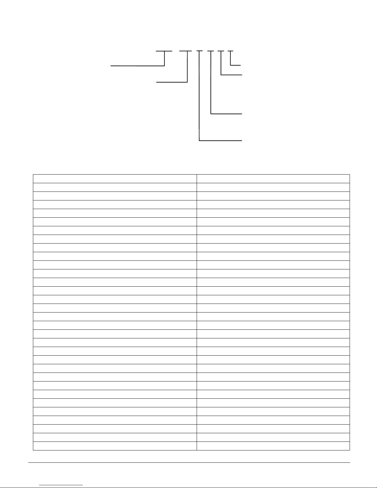
MODEL NOMENCLATURE
Model
ACU = Air Cooled Cooling Unit
Nominal Capacity (tons)
18 = 1-1/2
24 = 2
36 = 3
42 = 3-1/2
48 = 4
49 = 4
60 = 5
61 = 5
62 = 5
* 10 SEER Size 036, 049 and 060 only.
**10 SEER Size 060 only.
Table 1: Unit Nameplate Model Number Identifier
Unit Nameplate McQuay Model Number
CKL18-1L ACU018ARAY
CKL24-1L ACU024ARAY
CKL30-1L ACU030ARAY
CKL36-1L ACU036ARAY
CKL36-3L ACU036APAY
CKL42-1L ACU042ARAY
CKL49-1L ACU049ARAY
CKL49-3L ACU049APAY
CKL60-1L ACU060ARAY
CKL60-3L ACU060APAY
CKL60-4L ACU060AQAY
CKL62-1L ACU062ARAY
CLJ18-1C ACU018ARBY
CLJ24-1C ACU024ARBY
CLJ30-1C ACU030ARBY
CLJ36-1C ACU036ARBY
CLJ42-1C ACU042ARBY
CLJ48-1C ACU048ARBY
CLJ60-1C ACU060ARBY
CLT24-1B ACU024ARCY
CLT30-1B ACU030ARCY
CLT36-1B ACU036ARCY
CLT42-1B ACU042ARCY
CLT48-1B ACU048ARCY
CLT60-1B ACU060ARCY
CLQ24-1B ACU024ARDY
CLQ30-1B ACU030ARDY
CLQ36-1B ACU036ARDY
CLQ42-1B ACU042ARDY
CLQ48-1B ACU048ARDY
CLQ60-1B ACU060ARDY
ACU 018
A
RAY
Future Use
SEER
A = 10
B = 12
C = 13
D = 14
Voltage/Phase
P = 208-230/3/60*
Q = 460/3/60**
R = 208-230/1/60
Vintage
IM-800 Page 3
INTRODUCTION
General Description
These installation instructions cover the outdoor installation of
cooling only split systems from ½ to 5 tons. See the product
catalog applicable to your model for information regarding
specifications applicable to your model and accessories.
Receiving Inspection
McQuay products are carefully inspected prior to shipment
and the carrier has assumed responsibility for loss or damage
upon acceptance of the shipment.
Upon receiving your shipment, check all items carefully
against the Bill of Lading. Inspect the unit and/or accessories
for shipping damage as soon as they are received. Immediately file claims for loss or damage, either shipping or concealed, with the shipping company.
Check the unit nameplate to verify the model number and electrical characteristics are correct. In the event an incorrect unit
is shipped, it must be returned to the supplier and must NOT
be installed. The manufacturer disclaims all responsibility for
the installation of incorrectly shipped units.
Codes and Regulations
This product is designed and manufactured to permit installation in accordance with National Codes. System design
should, where applicable, follow information presented in
accepted industry guides such as the ASHRAE Handbooks. It
is the installer' s responsibility to install the product in accordance with National Codes and/or prevailing local codes and
regulations. The manufacturer disclaims all responsibility for
equipment installed in violation of any code or regulations.
Important Message to the Owner
Read these instructions carefully and keep them near the product for future reference. Although these instructions are
addressed primarily to the installer, useful maintenance information is included. Have the installer acquaint you with the
operation of the product and periodic maintenance requirements.
Recognize Safety Symbols, Words, and Labels
The following symbols and labels are used throughout this
manual to indicate immediate or potential hazards. It is the
owner's and installer's responsibility to read and comply with
all safety information and instructions accompanying these
symbols. Failure to heed safety information increases the risk
of property damage and/or product damage, serious personal
injury or death. Improper installation, operation and maintenance can void the warranty.
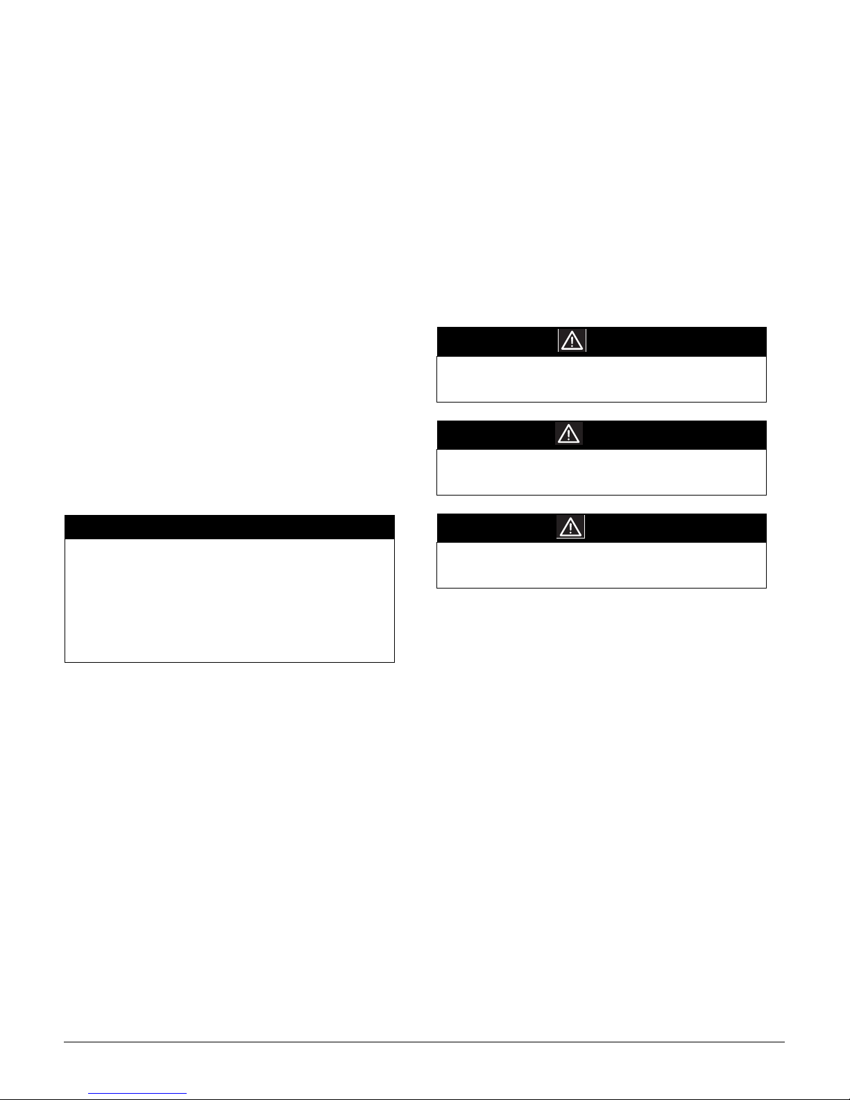
DANGER
Immediate hazards which WILL result in property
damage, product damage, severe personal injury and/
or death.
WARNING
Hazards or unsafe practice CAN result in property
damage, product damage, sever personal injury and/or
death.
IMPORTANT
The United States Environmental Protection Agency
(EPA) regulations cover introduction and disposal of
refrigerants in this unit. Failure to follow those
regulations can harm the environment and lead to
substantial fines. Because regulations can change over
time, a certified technician should perform any work
done on this unit. If you have any questions, please
contact the local office of the EPA.
Important Message to the Installer
This equipment is to be installed by an experienced installation
company and fully trained personnel. Carefully read all
instructions and take into account any special considerations
prior to installing the unit. Give this manual to the owner and
explain its provisions.
CAUTION
Hazards or unsafe practices which CAN result in
property damage, product damage, and/or personal
injury.
Replacement Parts
Replacement parts can be obtained by contacting McQuay at
1
-800-37-PARTS. When contacting McQuay for service or
replacement parts, refer to the model number and serial number of the unit as stamped on the nameplate attached to the
unit.
Page 4 IM-800

GENERAL WARNINGS
WARNING
Before servicing or installing, the electrical power must
be in OFF. More than one disconnect may exist.
Failure to disconnect all power can cause electrical
shock, serious personal injury or death.
WARNING
The unit must have an uninterrupted, unbroken
electrical ground. Failure to properly ground can cause
severe personal injury or death.
Figure 1. Clearances and Accessibility
Service Access
18" Min.
10" Min.
WARNING
Installation and service by trained, qualified technicians
only. High pressure and electricity can cause severe
personal injury or death. Observe ALL warnings
contained in this manual and the labels/tags attached to
the equipment.
WARNING
When installing or servicing, wear protective gloves,
gear and eyeware. Also observe special safety
requirements (hard hats etc.).
CCAUTION
To protect the unit when welding close to the painted
surfaces, use a quenching cloth to prevent scorching or
marring the equipment finish.
CCAUTION
Read these instructions before performing this
installation or servicing this unit. All installations must
be in accordance with all national, state, or local
building codes.
Service Access
18" Min.
Figure 2. Clearances and Accessibility
10" Min.
10"
10"
CLEARANCES AND ACCESSIBILITY
The condensing unit is designed to be located outside the
building with unobstructed condenser air inlet and discharge.
Additionally, the unit must be situated to permit access for service and installation. Condenser air enters from three sides.
Air discharges upward from the top of the unit. Refrigerant
tube electrical connections are made on the right side of the
unit as you face the compressor compartment. The best and
most common application is for the unit to be located 10” from
the back wall with the connection side facing the wall. Refer to
Figures 1 and 2. This “close to the wall” application minimizes exposed tubing and wiring and reduces the space for
children to run around the unit. This will help to avoid possible damage to the tubes or wiring and/or personal injury.
IM-800 Page 5
Close to the wall application provides free, unobstructed air to
the other two sides. In more confined application spaces, such
as corners, provide a minimum 10” clearance on all air inlet
sides. Allow 18” minimum for service access to the compressor compartment and controls.
The top of the unit should be completely unobstructed. If units
are to be located under an overhang, there should be a minimum of 36” clearance and provisions made to deflect the
warm discharge air out from the overhang.

LOCATION
If unit is to be located under an overhang, there should be a
minimum of 36” clearance and provisions made to deflect the
water discharge air out from the overhang. If the outdoor unit
is mounted above the air handler, the maximum lift should not
exceed 70’ (suction line). If the air handler is mounted above
condensing unit, the lift should not exceed 50’ (liquid line.).
Refer to Figure 3 and Table 2 for maximum refrigerant line
lenghts.
Figure 3. Maximum Refrigerant Line Lengths
70' MAX
CONDENSING UNIT
LIQUID LINE
CONDENSING UNIT
CONDENSING UNIT
LIQUID LINE
SUCTION LINE OIL TRAPS WHEN INDOOR UNIT
IS 4 FEET OR MORE BELOW OUTDOOR UNIT
INVERTED LOOP
PITCH SUCTION LINE TOWARD OUTDOOR
UNIT 1/2" FOR EVERY 10' OF LINE
LIQUID LINE
EVAPORATOR BLOWER
SUCTION LINE
EVAPORATOR BLOWER
ADDITIONAL SUCTION LINE OIL
TRAP FOR EACH 20' RISE OF PIPE
EVAPORATOR BLOWER
8'
50' MAX
ELECTRICAL
Electrical installation will consist of power supply wiring to
the condensing unit, as well as control wiring between thermostat, indoor unit and the condensing unit as shown on wiring
diagram. All wiring must be in accordance with National
Electrical Code and/or local codes that may apply.
The condensing unit rating plate lists pertinent electrical data
necessary for the selection of proper size electrical service and
over-current protection. The installer should make the owner
familiar with the location of the over-current protection, the
proper size for this application, and the proper procedure for
disconnecting power service to the unit.
The condensing unit control wiring requires a 24 Volt minimum 25 VA service from the indoor transformer as shown on
the wiring diagram.
REFRIGERANT TUBING
Use only refrigerant grade (dehydrated and sealed) copper tubing of the size indicated in Table 1 to interconnect the condensing unit with the indoor evaporator. Take extreme care to keep
the refrigerant tubing clean and dry prior to and during installation.
Do not remove plugs from ends of tubing until connection is
ready to be made. Suction line insulation is necessary to prevent condensation from forming on and dropping from suction line. Generally 3/8" wall thickness of Armflex or
equivalent is satisfactory. In severe applications (hot, high
humidity areas) greater thickness may be required. Apply suction line insulation by sliding it on the sealed tubing before
cutting and making connections.
Table 2: Maximum Refrigerant Line Lengths
REFRIGERANT LINE LENGTH (Ft)
Cond
Unit
Ton s
1 1/2 5/8 1/4 3/4 3/8 3/4 3/8
2 5/8 1/4 3/4* 3/8 3/4 3/8
2 1/2 3/4 3/8 3/4** 3/8 7/8 3/8
3 3/4 3/8 3/4** 3/8 7/8 3/8
3 1/2 3/4 3/8 7/8** 3/8 1 1/8 3/8
4 7/8 3/8 1 1/8 3/8 1 1/8 3/8
5 7/8 3/8 1 1/8 3/8 1 1/8 3/8
0-24 25-49 50-74***
Line Diameter (In. OD)
Suct Liq Suct Liq Suct Liq
* 7/8" required for full ratings
** 1 1/8" required for full ratings
The condensing unit must be mounted on a solid, level foundation (i.e. pre-formed concrete slab or other suitable base). For
rooftop application, verify that the building construction can
support the weight and that proper consideration is given to the
weather-tight integrity of the roof. The condensing unit contains moving components and can vibrate. Therefore, sound is
also a consideration in rooftop application. Since this unit discharges warm condenser air from the top with cooler air being
drawn in three sides, plantings can be made in relatively close
proximity to the unit. However, debris on the fan coil surface
reduces product efficiency. Avoid lawn mower discharge
toward the unit.
EVAPORATOR COIL
Suction and liquid lines are under pressure. Point lines away
from persons and obects that can be damaged. Use extreme
care when removing caps. Use fittings on the liquid line to
remove pressure.
Do not remove caps until installation is complete and final
connections are to be made.
Field Connection to the Valve and Valve Opening
1. Cut tubing square. Make sure it is round and free of burrs
at the connecting ends. Clean the tubing to prevent contaminants from entering the system.
2. Wrap a wet rag around the copper valve stub before braz-
ing.
3. Braze or silver solder the joint.
4. After brazing, quench with a wet rag to cool the joint.
Evacuate and charge the connecting lines as outlined in this
manual.
5. Remove the valve top cap. It is important to keep the cap
in a clean area to provide proper sealing once replaced.
6. Using a standard L shaped Allen wrench, break open the
valve body. To expedite opening the valve body after it is
broken, use a ratchet wrench with a short Allen stub.
Please note that it is normal to see oil on the valve stem
body once the cap is removed.
7. Replace the valve cap and tighten with a wrench, making
sure that the the cap is sealed.
Page 6 IM-800

QUICK CONNECT COILS
Precharged System Installation
Installation procedure will differ when condensing units are
provided for use with precharged refrigerant coils and lines.
Condensing units are provided with #6 and #11 male quick
connects instead of liquid and suction valves attached to cabinet to contain the R-22 charge that is sufficient for matching
evaporator coils and 15’ of interconnecting lines.
Coils are provided with #6 and #11 male quick connects. Line
sets are required with #6 and #11 female quick connects on
both ends. Access ports are required in the fittings of both liquid and suction lines at condenser end. Both coil and line sets
include R-22 holding charge only.
1. Connect lines to evaporator coil before connecting to the
condensing unit, locating access ports adjacent to condensing unit.
a. Form tubing so it properly aligns with the coil connec-
tions.
b. Remove plugs and caps from connections.
c. Check to verify mating surfaces are clean.
d. Lubricate rubber seal with clean refrigerant oil and
thread couplings together by hand to verify they are not
cross threaded.
e. Tighten connections using backup wrench on stationary
fitting until coupling bottoms; then tighten 1/6 turn to
complete knife edge seal.
SYSTEM START UP
Processing Checks
Condensing units are supplied with R-22 charge sufficient for
typical matching evaporator and approximately 15’ of interconnecting tubing. Condensing unit liquid and suction valves
are closed to contain the charge within the unit.
The recommended procedure for processing and charge adjustment is as follows:
1. Connect vacuum pump to both base valve service ports.
2. Evacuate tubing and evaporator through liquid and suction
base valve ports, to 500 microns or less for a minimum of
30 minutes. Close valve to pump and wait 15 minutes.
Vacuum should not rise above 800 microns. If unable to
obtain 500 micorns, or vacuum rises above 800 microns
over a 15 minute period, discontinue evacuation, pressurize
and check for leaks. Repair any leaks found and repeat
step 2.
3. Close valve to vacuum pump and stop pump. Break vacuum by opening liquid and suction base valves. Fully open
base valves and remove pump lines. Connect service
gauges to verify lines are purged.
4. Set thermostat system switch to “COOL” and temperature
to highest setting. Close all disconnects.
5. Set thermostat to call for cooling. Check for operation of
indoor and outdoor fans. Allow for at least 10 minutes.
6. Check charge and adjust if necessary. Refer to appropriate
“Check Charge” section.
2. Connect lines to condensing unit in the same manner as to
evaporator coil. Observe same precautions.
3. After making all connections and opening valves, check all
piping for leaks.
IM-800 Page 7

CHARGE CHECKS
Capillary Tube/Fixed Orifice System
1. Fully open both base valves.
2. Connect service gauge manifold to base-valve service ports
to purge lines. Run system at least 10 minutes to allow
pressure to stabilize.
3. Temporarily install thermometer on suction (large) line
near condensing unit. Provide good contact between the
thermometer and line. Wrap thermometer with insulating
material to provide an accurate reading.
4. Refer to Table 3 for proper system superheat. Add charge
to lower superheat. Remove charge to raise superheat.
5. Remove gauge lines carefully.
CWARNING
Escaping liquid refrigerant can cause burns. Wear
protective gloves, gear and eyewear.
Table 3: System Superheat
AMBIENT CONDENSER INLET
TEMPERATURE (
o
F DB)
100
95
90
85
80
75 5 10172529
70 5 14202832
65 13 19 26 32 35
60 17 25 30 33 37
RETURN AIR TEMPERATURE (
65 70 75 80 85
579
71218
5101720
5122126
Superheat Determination
1. Read suction pressure. Using Table 4, determine saturated
suction temperature.
2. Read suction line temperature.
3. Use the following formula to determine superheat:
Superheat = Suction Line Temp. - Saturated Suction Temp.
Table 4: Saturated Suction Pressure (R-22)
SUCTION PRESSURE PSIG
50 26
53 28
55 30
58 32
61 34
63 36
66 38
69 40
72 42
75 44
78 46
81 48
SATURATED SUCTION
TEMPERATURE
o
F DB)
55
o
F
Expansion Valve System
1. Fully open both base valves.
2. Connect service gauge manifold to base-valve service parts
making sure lines are purged. Run system at least 10 minutes to allow pressure to stabalize.
3. Temporarily install the thermometer to liquid (small) line
near condensing unit. Provide good contact between thermometer and line. Wrap thermometer with insulating
material to provide an accurate reading.
4. Referring to Table 5, adjust charge to obtain a temperature
12-15°F below the saturated liquid temperature.
Example:
If the Liquid Pressure is 260 psig then the Saturated Temperature will be 120°F. Adjust the Saturated Temperature by subtracting 12-15°F. This will give you a Liquid Line
Temperature of 105° - 108°F.
Table 5: Saturated LIquid Temperature
LIQUID PRESSURE PSIG
200 102
210 105
220 108
230 111
240 114
250 117
260 120
270 123
280 126
290 128
300 131
SATURATED TEMPERATURE
o
F
SPECIAL NOTE: For systems with more than 15’ of interconnecting tubing, please refer to Table 6 for line charge
allowance per foot of tubing.
Table 6: Line Charge Allowance (R-22 - oz./ft.)
LINE O.D. (IN) LIQUID LINE SUCTION LINE
1/4 0.22
3/8 0.58
1/2 1.14
5/8 1.86 0.04
3/4 0.06
7/8 0.08
1 1/8 0.15
1 3/8 0.22
NOTE: Systems with over 50’ separation between condensing unit and evaporator may require oil charge adjustment
(Table 7).
Table 7: Oil Charge Adjustment
UNIT MODEL
(TONS)
1 - 1 1/2 0.25
2 - 5 0.5
*Use either Texaco WF-32 (formerly cappella B) or Suniso 3G-S oil.
ADDITIONAL OIL CHARGE PER EACH ADDI-
TIONAL 10’ OF LINE (OZ)*
Page 8 IM-800

WIRING DIAGRAM - SINGLE PHASE
FAN MOTOR
COMPRESSOR
SC
Y
R
R
BK
BK
CRANKCASE HEATER IF USED
WIRING C ODE
HIGH VOLTAGE
LOW VOLTAGE
WIRE NUT
OPTIONAL START ASSIST
PU
BK
BK
OUTDOOR CONTROL BOX
BR
FACTORY
WIRING
C
R
F
HERM
Y
COMPRESSOR/FAN
CAPACITOR
START ASSIST
Y
(START ASSIST
IF USED)
PU
FIELD
WIRING
PU
R
Y
R
Y
WIRING FOR
FACTORY
OPTIONS
BR
NOTES:
REPLACEMENT WIRE MUST BE SAME
GAGE AND INSULATION THICKNESS,
105° C APPLIANCE W IRING MATERIAL.
BK
PU
BK
BK
ALT. DOUBLE
POLE CONTACTOR
T1
T2
C
L2
O
N
T
L2
BK
PU
R
R
T2
T1
L2
L1
CONNECT TO APPROP.
CONTROL CIRCUIT HAVING
MIN. 40 VA 24 VOLT
N.E.C. CLASS 2
TRANSFORMER OR FOR
CERTIFIED C.S.A.
INSTALLATION. USE C.S.A.
CERTIFIED ENERGY LIMITED
CLASS 2 TRANSFORMER.
COLOR CODE
BK
R
Y
BL
PU
LTBL
BR
G
L1
OUTDOOR POWER
SUPPLY - (SEE
UNIT RATING
PLATE)
USE COPPER
CONDUCTORS ONLY
USE L1 FOR
NEUTRAL OR
GROUNDED SUPPLY
IF USED
EQUIPMENT GROUND
BLACK
RED
YELLOW
BLUE
PURPLE
LIGHT BLUE
BROWN
GREEN
A
C
T
O
T2
R
THERMOSTAT
R
R
OUTDOOR POWER SUPPLY
COMPRESSOR
MOTOR
START ASSIST
(IF USED)
THERMOSTAT
FAN SWITCH
THERMOSTAT
COOL
ANTICIPATOR
BULB
THERMOSTAT
ADJ. HEAT
ANTICIPATOR
R
S
ON
AUTO
COOL
HEAT
CRANKCASE HEATER
(IF USED)
C
COMPRESSOR
INTERNAL
OVERLOAD
G
FAN RELAY
Y
THERMOSTAT
SYSTEM
SWITCH
W
LOW VOLTAGE
TRANSFORMER
FAN MOTOR
CAPACITOR
OFF
24V
CONTACTOR
COIL
COIL
COIL
L1
C
O
N
T
A
C
T
O
T1
R
C
INDOOR POWER SUPPLY
IM-800 Page 9

WIRING DIAGRAM - THREE PHASE
HP
Y
BR
V
BK
BK
R
Y
T3
L3
Y
BK
R
S
C
COMP
V
FC
POWER SUPPLY
MAIN
AUX
CM
IO
BR
V
BR
BK
R
(SEE RATING PLATE)
USE COPPER CONDUCTORS ONLY
R
BL
V
T1BLT2
L1CL2
BK
BK
BK
BK
CH
V
Y
CONNECT TO APPROP. CONTROL
CIRCUIT HAVING
N.E.C. CLASS 2
CERTIFIED C.S.A
CERTIFIED ENERGY
TRANSFORMER.
COPPER CONDUCTORS ONLY
R
MIN. 40 VA. 24 VOLT
TRAMSFORMER OR FOR
INSTALLATION. USE C.S.A.
LIMITED CLASS 2
EQUIPMENT GROUND USE
COLOR CODE
BK
BLACK
R
RED
Y
YELLOW
BL
BLUE
V
VIOLET
LTBL
LIGHT BLUE
BR
BROWN
G
GREEN
O
ORANGE
W
WHITE
USE N.E.C. CLASS 2 WIRE
C
L3
T3
R
THERMOSTAT
BULB
R
OUTDOOR POWER SUPPLY
L2
C
T2
2
3
COMP
THERMOSTAT
FAN SWITCH
THERMOSTAT
COOL
ANTIC IPATOR
THERMOSTAT
ADJ. H EAT
ANTIC IPATOR
CH
1 CAP
ON
G
AUTO
Y
COOL
OFF
HEAT
24V
THERMOSTAT
SYSTEM
SWITCH
COIL
W
LOW VOLTAGE
TRANSFORMER
MOTOR
CONTACTOR
COIL
FAN RELAY
COIL
L1
L1
C
C
T1
T1
P
H
C
HIGH VOLTAGE
LOW VOLTAGE
WIRE NUT
LINE SPLICE
WIRING CODE
FACTORY WIRING
FIELD WIRING
COMPONENT CODE
OUTDOOR FAN MOTOR
CM
COMPRESSOR
COMP
CONTACTOR
C
DEFROST CONTROL
DC
LOW VOLTAGE DEFROST RELAY
LDVR
CRANKCASE HEATER
CH
INTERNAL OVERLOAD
IO
LOW PRESSURE CONTROL
LP
HIGH PRESSURE CONTROL
HP
OUTDOOR THERMOSTAT (OPTIONAL)
OT
FAN CAPACITOR
FC
DEFROST THERMOSTAT
DFT
REVERSING VALVE COIL
RVC
HIGH VOLTAGE DEFROST RELAY
HVDR
CONTROLS SHOWN WITH UTILITIES
IN 'ON'POSITION
IN 'OFF' POSITION.
AND THERMOSTAT
INDOOR POWER SUPPLY
NOTES:
1) TO INDOOR UNIT LOW
VOLTAGE TERMINAL BLOCK &
INDOOR THERMOSTAT.
2) SEE INDOOR UNIT &
OUTDOOR UNIT INSTALLATION
INSTRUCTIONS FOR CONNECTION
OF OPTIONAL OUTDOOR THERMOSTAT.
Page 10 IM-800

IM-800 Page 11

This document contains the most current product information as of this printing. For the most up-to-date
product information, please go to www.mcquay.com.
www.mcquay.com • 800-432-1342
 Loading...