

Page 1
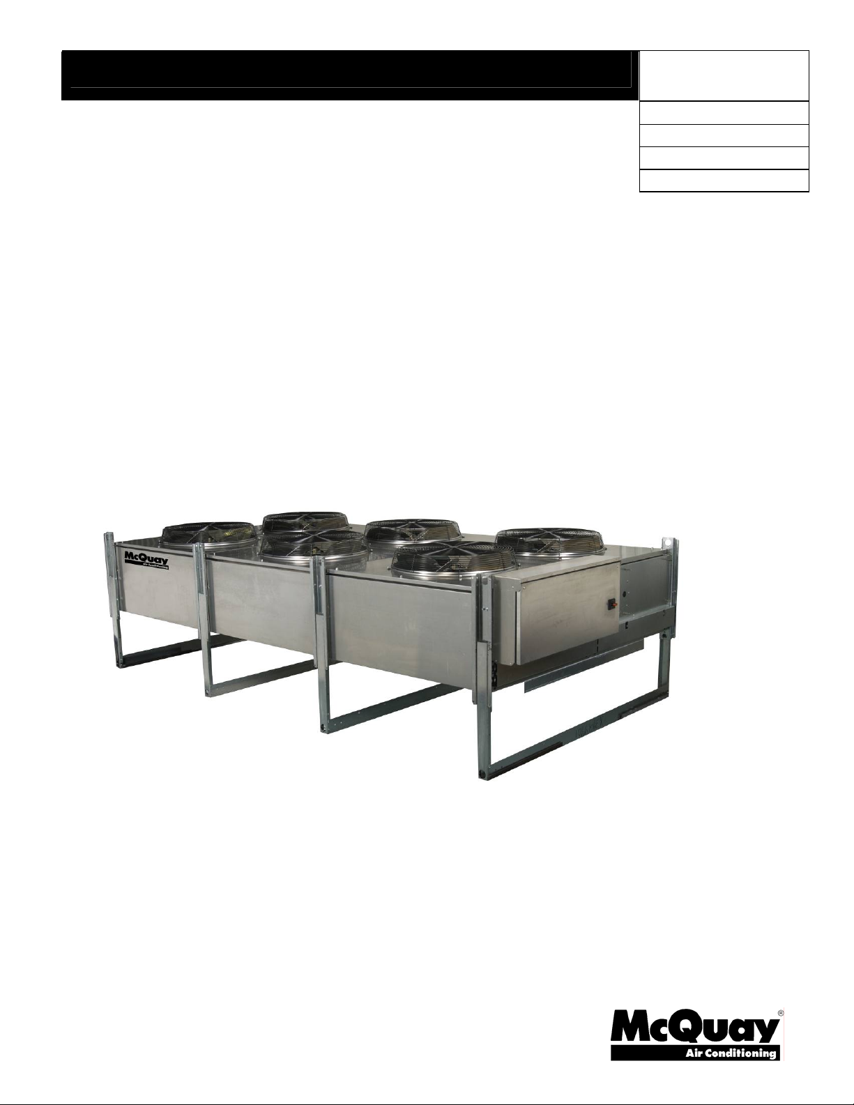
Installation, Operation and Maintenance Manual
IOMM A-C Cond
Air-Cooled Condensers
Model ACH 014 - 225
Model ACX 014 - 225
Model ACL 014 - 225
Capacities from 130 MBH to 2225 MBH
R-22, R-134a
Group: Chiller
Part Number: 331376901
Effective: AUGUST 2007
Supersedes:
JULY 2007
Page 2
Table of Contents
Introduction................................................................................... 3
Installation..................................................................................... 3
Handling .........................................................................................................3
Holding Charge...............................................................................................3
Unit Location..................................................................................................4
Sound/Vibration..............................................................................................4
Rigging ...........................................................................................................5
Walls or Obstructions......................................................................................5
Multiple Units.................................................................................................6
Units in Pits.....................................................................................................6
Decorative Fences...........................................................................................6
Dimensions..................................................................................... 7
Refrigerant Piping......................................................................... 8
Refrigerant Piping...........................................................................................8
Valves..............................................................................................................8
Discharge Lines ..............................................................................................9
R-410A ...........................................................................................................9
Physical Data...............................................................................10
Electrical Data..............................................................................11
Operation..................................................................................... 18
Start-Up.........................................................................................................18
Discharge Gas Pulsation...............................................................................18
Discharge Pressure Control ..........................................................................18
Fan/Circuit Configuration .............................................................................18
Control options:............................................................................................19
Maintenance ................................................................................ 26
Cleaning Instructions....................................................................................26
Manufactured in an ISO certified facility
©2007 McQuay International
Illustrations cover the general appearance of McQuay International products at the time of publication and we reserve the right
to make changes in design and construction at anytime without notice.
2 IOMM A-C Cond
Page 3
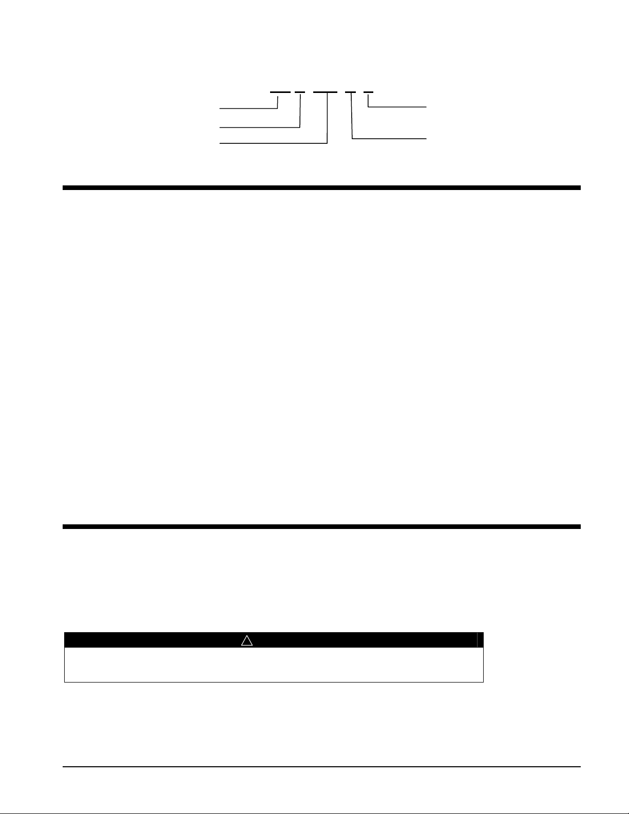
MODEL CODE
AC H 100 A S
Air-cooled Condenser
Series: H, L, X
Nominal Evaporator Tons
Fan Rows/Circuits
S=Single, D=Dual
Vintage
Introduction
Carefully check each shipment against the bill of lading and account for all items. Report any shortage or
damage to the delivering carrier.
On receipt of equipment, check the unit nameplate for correct electrical characteristics and working pressure.
Refrigerants R-22, R-134a, R-407c have 450 psi; R-410a has 650 psi.
Be careful to prevent damage when uncrating. Heavy equipment should be left on unit’s shipping base until it
has been moved to the final location.
This equipment must be installed in accordance with accepted industry standards. Failure to meet the following
conditions may void the warranty:
1. System piping must be installed following industry standards for good piping practices.
2. Inert gas must be charged into piping during brazing/welding.
3. System must be thoroughly leak-checked and evacuated before initial charging. High vacuum gauge capable
of reading microns is mandatory. Dial indicating pressure gauges are not acceptable.
4. Power supply to system must meet the following conditions:
Voltage for 208/230 motors not less than 195 volts or more than 253 volts.
All other voltages must be within 10% of nameplate ratings.
Phase imbalance not to exceed 2%.
5. All controls and safety switch circuits properly connected per wiring diagram.
6. Factory installed wiring must not be changed without written factory approval.
7. Relief valves must meet all code requirements.
Installation
Handling
Note: Installation and maintenance are to be performed only by qualified personnel who are familiar with local
codes and regulations, and experienced with this type of equipment.
Avoid rough handling shock due to impact or dropping the unit. Do not push or pull the unit.
Never allow any part of the unit to fall during unloading or moving, as this can result in serious damage.
! DANGER
Improper lifting or moving of unit can result in property damage, severe personal injury
or death. Follow rigging and moving instructions carefully.
Holding Charge
The unit is shipped with a holding charge of dry nitrogen under nominal pressure.
IOMM A-C Cond 3
Page 4
Unit Location
Units are designed for outdoor application and may be mounted on a roof or concrete slab (ground level
installation). Install roof-mounted units on steel channels or an I-beam frame to support the unit above the roof.
Use of vibration pads or isolators is recommended. The roof must be strong enough to support the operating
weight of the unit.
For ground level installation, mount units on a one-piece concrete slab with footings extending below the frost
line. Be certain concrete slabs are installed level and are properly supported to prevent settling.
Locate the condenser far enough away from any wall or other obstruction to provide sufficient clearance for air
entrance. Do not attach ductwork to the coil inlet or fan outlet. Avoid air recirculation conditions that may be
caused by sight screening, walls, etc. and keep unit fan discharge away from any building air intakes. Do not
install unit where exhaust or ventilation equipment will affect entering air temperature or foul coils.
! WARNING
Warnings indicate potentially hazardous situations, which can result
in property damage, severe personal injury, or death if not avoided.
This equipment may contain a substance which harms the public
health and environment by destroying ozone in the upper
atmosphere. Venting of certain refrigerants to the atmosphere is
illegal. Refrigerant recovery devices must be used when installing or
servicing this product.
Sound/Vibration
Install units away from occupied spaces, utility areas, corridors and auxiliary spaces to reduce the transmission of
sound and vibration to occupied spaces. The refrigerant piping should be flexible enough to prevent the
transmission of noise and vibration from the unit into the building. If the refrigerant lines are to be suspended
from the structure of the building, use isolation hangers to prevent the transmission of vibration. Where piping
passes through a wall, pack fiberglass and sealing compound around the lines to minimize vibration and retain
flexibility. The unit must be secured in its final location. Holes are provided in the base runner for this purpose.
4 IOMM A-C Cond
Page 5
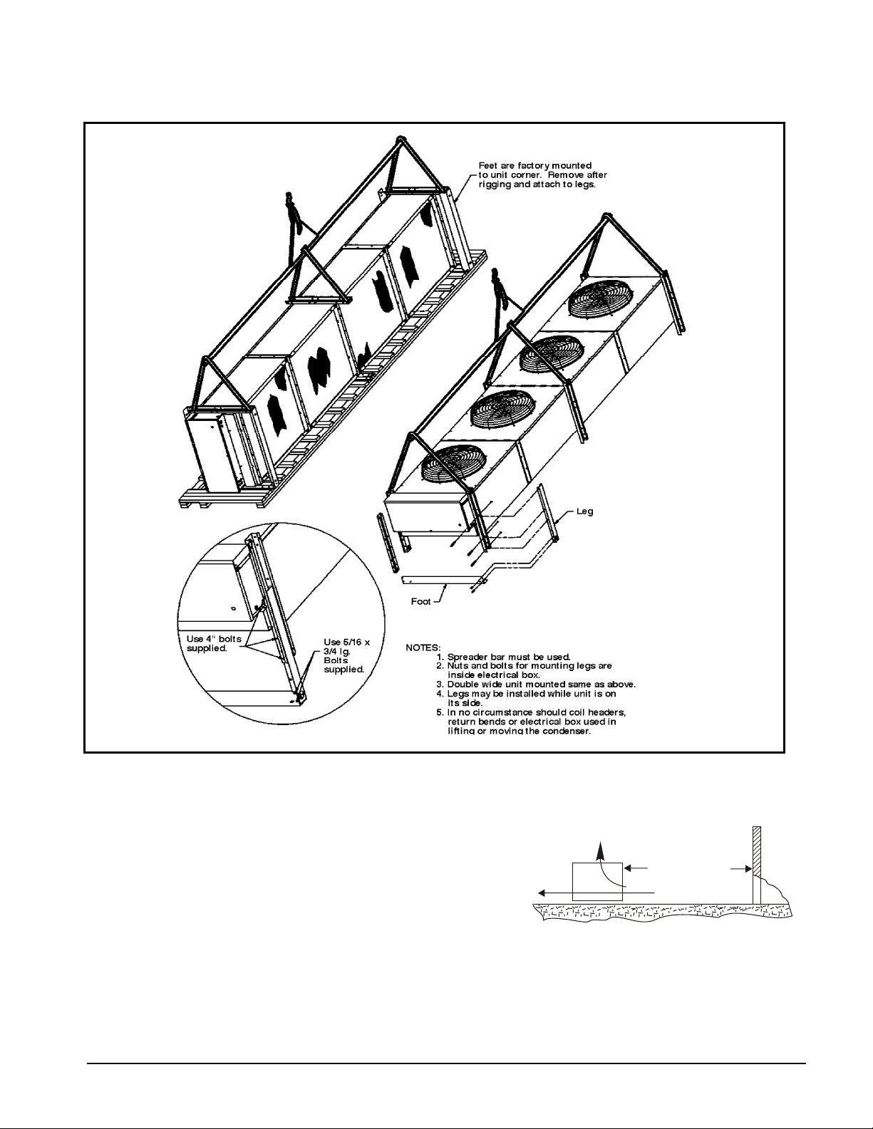
Rigging
A
A
A
Figure 1, Unit Rigging
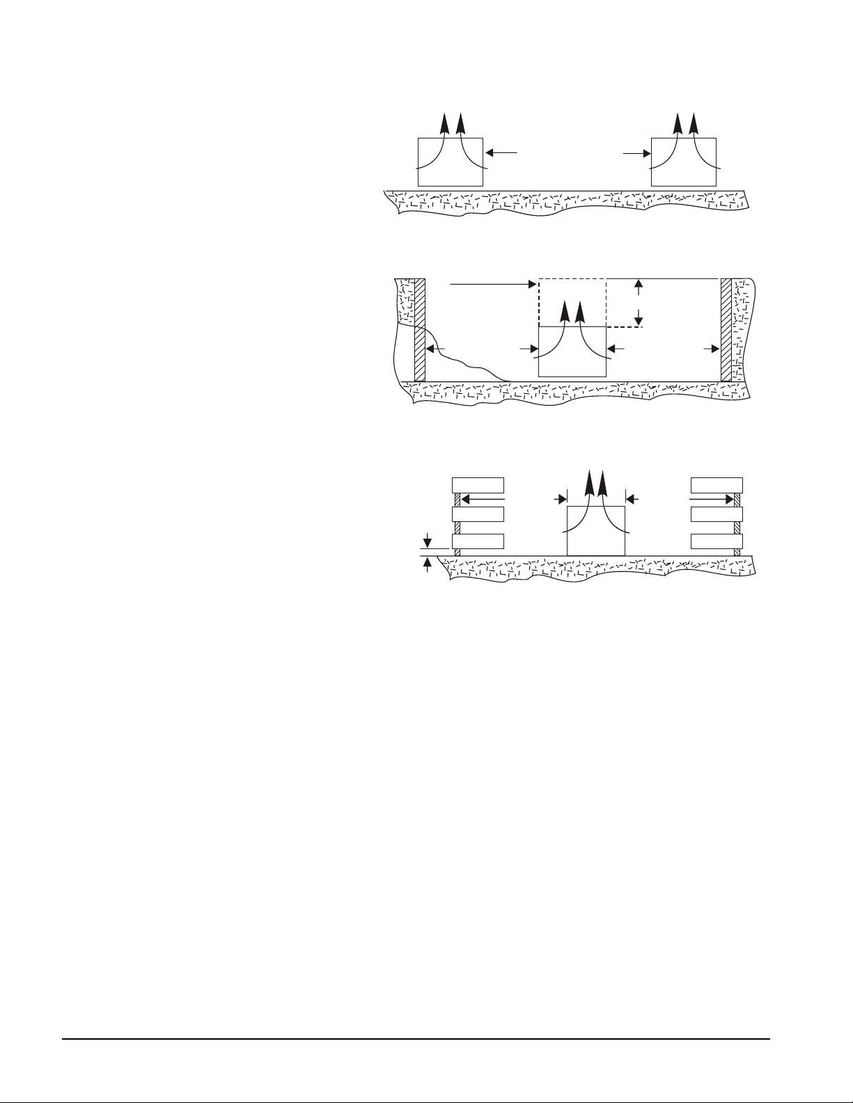
Walls or Obstructions
Locate the unit to ensure air can circulate freely and not be
recirculated. For proper air flow and access, maintain the
minimum distance from the unit to the wall as shown to the right.
Increase this distance whenever possible. Leave maintenance
room through access doors and panels. Overhead obstructions are
not permitted. When enclosed by three walls, install unit as
indicated for units in a pit.
IOMM A-C Cond 5
IR FLOW
CH = 4 ft.
CL/ACX = 6 ft.
Page 6
Multiple Units
A
A
A
A
A
A
A
A
A
A
A
A
A
A
For units placed side by side, the minimum
distance between units must be as shown to
the right. If units are placed end to end, the
minimum distance between units is 4 feet.
Units in Pits
The top of the unit should not be more than two
feet below top of the pit, and side distance
should be as shown. If the top of the unit is not
level with the top of pit, discharge cones or
stacks must be used to raise discharge air to the
top of the pit. This is a minimum requirement.
Decorative Fences
Fences must have 50% free area, with 1 foot
undercut, at least the width of condenser minimum
clearance, and must not exceed the top of unit. If
these requirements are not met, unit must be
installed as indicated for "Units in pits".
IR FLOW
1 IN.
MIN.
STACK
(BY OTHERS
IF SUPPLIED)
CH = 4 ft.
CL/ACX = 6 ft.
CH = 6 ft.
CL/ACX = 8 ft.
IR
FLOW
CH = 3 ft
.
CL/ACX
= 4 ft.
2 FT. MAX.
IR FLOW
IR FLOW
CH = 4 ft.
CL/ACX = 6 ft.
CH = 3 ft
CL/ACX
= 4 ft.
6 IOMM A-C Cond
Page 7
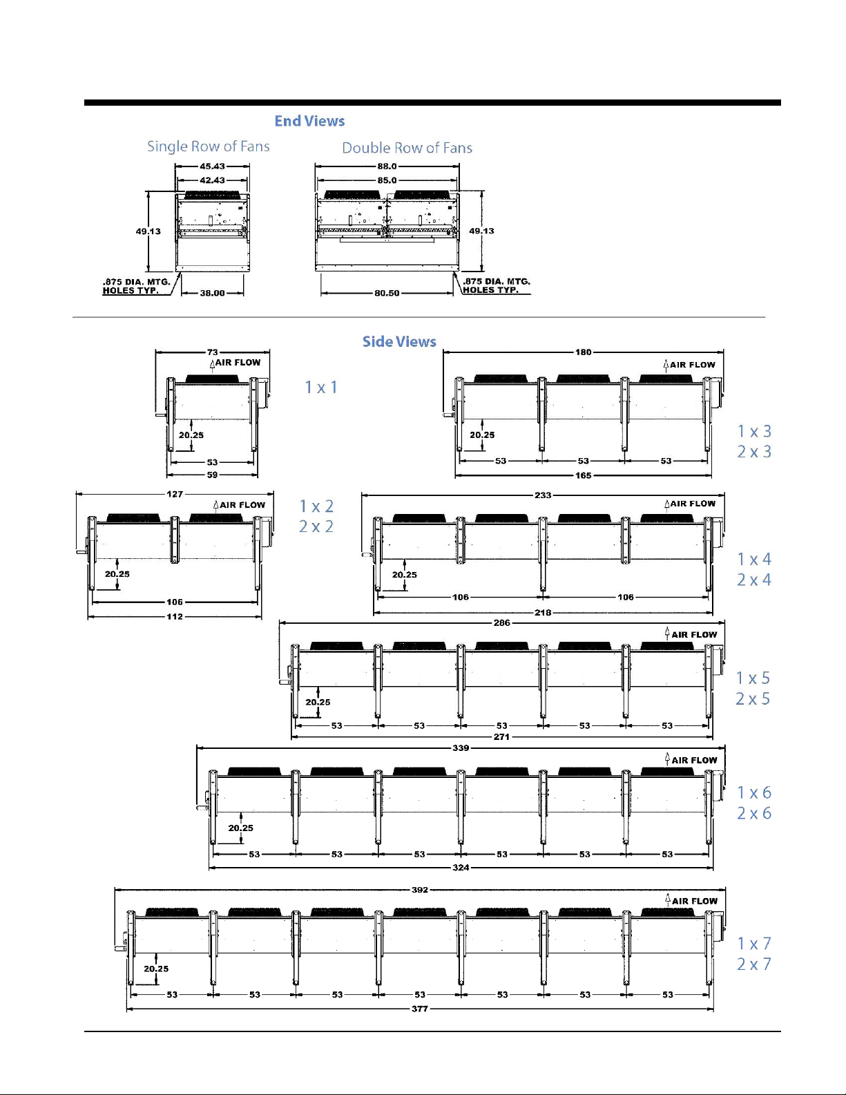
Dimensions
Note: All dimensions in inches
unless otherwise indicated
IOMM A-C Cond 7
Page 8
Refrigerant Piping
R
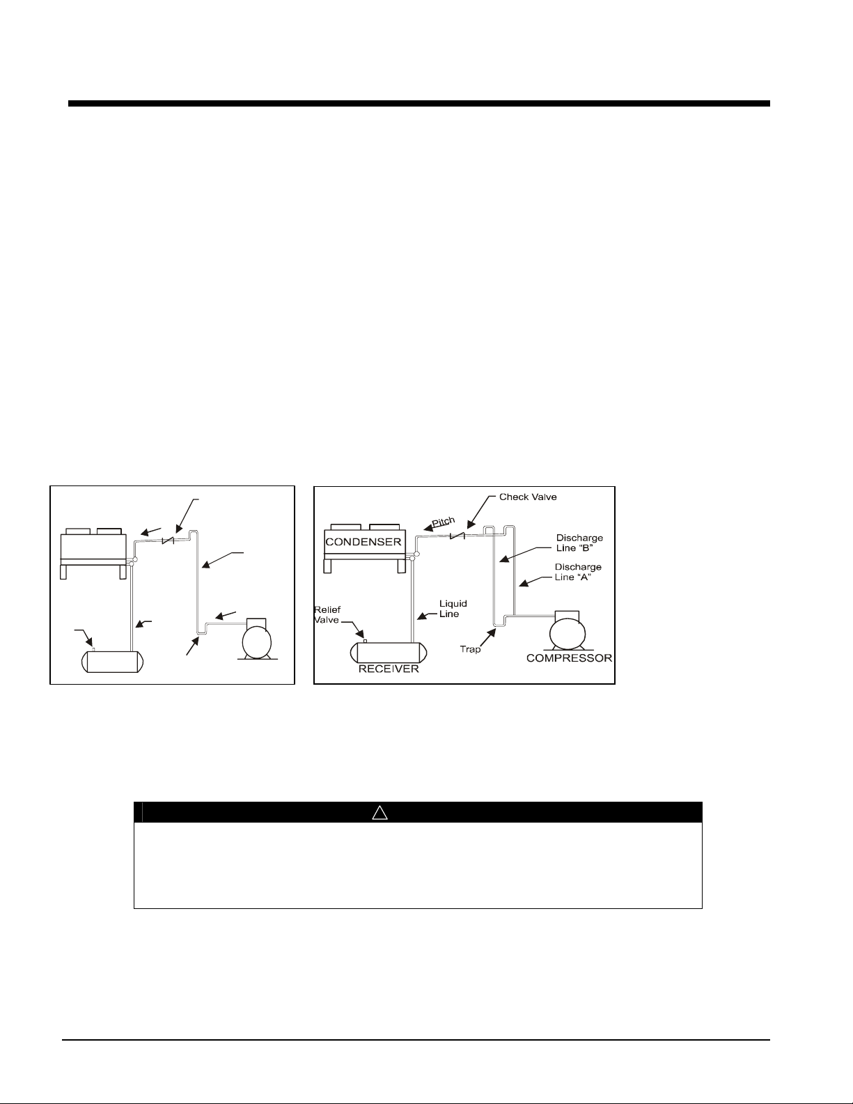
Figure 2 illustrates a typical piping arrangement involving a remote condenser located at a higher elevation, as
commonly encountered when the condenser is on a roof and the compressor and receiver are on grade level or in
a basement equipment room. In this case, the design of the discharge line is very critical. If properly sized for
full load condition, the gas velocity might be too low at reduced loads to carry oil up through the discharge line
and condenser coil. Reducing the discharge line size would increase the gas velocity sufficiently at reduced load
conditions; however, when operating at full load, the line would be greatly undersized, and thereby create an
excessive refrigerant pressure drop. This condition can be overcome in one of the two following ways:
1. Size discharge line for the desired pressure drop at full load conditions and install an oil separator at the
bottom of the trap in the discharge line from the compressor.
2. Use a double riser discharge line as shown in
Figure 2
conditions and size line "B" at full load conditions; both lines should have sufficient flow velocity to carry
the oil to the condenser.
For more complete information, see the ASHRAE Handbook on Systems.
Be aware of the following when fabricating piping:
All oil traps are to be as short in radius as possible. The trap may be fabricated using three 90- degree ells. •
Use pressure relief valves at the condenser to protect the coil.
•
Use a drain line check valve when the condenser is at a lower temperature than the receiver.
•
Figure 2, Typical and Double Riser Discharge Piping Arrangement
. Size line "A" to carry the oil at minimum load
CONDENSER
Check Valve
h
c
t
i
P
Discharge
Line
Relief
Valve
RECEIVE
Typical Piping Arrangement
Liquid
Line
Trap
h
c
t
i
P
COMPRESSOR
Double Riser Discharge Piping Arrangement
Refrigerant Piping
Install piping according to standard accepted refrigeration practice. See Ta b le 1 and Ta bl e 2 for discharge and
liquid drain line sizes for remote condenser connections. Use only refrigeration grade copper tubing and put dry
nitrogen through lines while brazing.
! CAUTION
Cautions indicate potentially hazardous situations which can result in
personal injury or equipment damage if not avoided.
Do not use soft solder joints. Do not leave dehydrated piping or
components open to the atmosphere any longer than is absolutely
necessary.
Valves
Equip major components with isolation valves and install a relief valve in the discharge line between the check
valve and the condenser inlet isolation valve.
8 IOMM A-C Cond
Page 9
Discharge Lines
Design discharge lines so that refrigerant pressure drop is minimized (high pressure losses cause increased
compressor horsepower) and a sufficiently high gas velocity to carry oil through to the condenser coil and
receiver at all loading conditions is maintained.
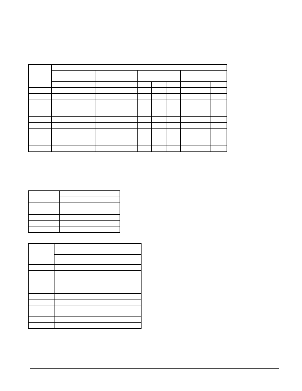
Table 1, Discharge Line Sizing
Line Size
Type L
Copper
OD (in.)
1/2
5/8
7/8
1 1/8
1 3/8
1 5/8
2 1/8
2 5/8
3 1/8
3 5/8
4 1/8
Notes:
1. Source: ASHRAE Refrigeration Handbook:
2. Line sizes based on pressure drop equivalent to one degree F. per 100 equivalent feet
3. Values in Table are based on 105°F condensing temperature. Multiply Table capacities by the factors in
4. If the line is short, a smaller line size may be used and very long lines may require larger sizes.
128.2 132.2 136.2 86.7 91.2 95.5 130.5 136.0 141.2 198.4 204.3 209.0
190.3 196.2 202.1 129.0 135.0 142.0 193.3 201.4 209.2 293.9 302.7 309.6
267.8 276.1 284.4 181.0 191.0 200.0 272.6 284.0 295.0 413.8 426.1 435.9
temperatures.
R-22 R-134a R-407C R-410A
Sat. Suction Temp. Sat. Suction Temp. Sat. Suction Temp Sat. Suction Temp
0°F 20°F 40°F 0°F 20°F 40°F0°F 20°F 40°F0°F 20°F 40°F
0.8 0.8 0.8 0.5 0.6 0.6 0.8 0.9 0.9 1.3 1.3 1.3
1.5 1.6 1.6 1.0 1.1 1.1 1.5 1.6 1.7 2.4 2.4 2.5
4.0 4.1 4.2 2.7 2.8 2.9 4.1 4.2 4.4 6.2 6.4 6.5
8.0 8.3 8.5 5.4 5.7 6.0 8.2 8.5 8.9 12.5 12.9 13.2
14.0 14.4 14.8 9.4 9.9 10.4 14.2 114.8 15.4 21.7 22.4 22.9
22.1 22.7 23.4 14.9 16.7 16.4 22.5 23.4 24.3 34.3 35.3 36.1
45.7 47.1 48.5 30.8 32.4 34.0 46.5 48.4 50.3 70.8 72.8 74.6
80.4 82.9 85.4 54.4 57.2 59.9 82.0 85.4 88.7 124.5 128.3 131.2
Discharge Line Capacity in Evaporator Tons
Table 2 for other condensing
Table 2, Condensing Temperature Correction Factor
Condensing
Temperature
90°F
100°F
110°F
120°F
130°F
Discharge Line
R-22 R-404, R-507
0.88 0.91
0.95 -0.97
1.04 1.02
1.10 1.08
1.18 1.16
Table 3, Liquid Line Sizing
Line Size
Type L
Copper
OD (in.)
1/2
5/8
7/8
1 1/8
1 3/8
1 5/8
2 1/8
2 5/8
3 1/8
3 5/8
4 1/8
In Evaporator Tons at 100 FPM Velocity
R-22 R-134a R-407C R-410A
13.2 12.1 37.9 45.8
20.2 18.4 66.2 79.7
28.5 26.1 104.7 125.9
49.6 45.3 317.1 260.7
76.5 69.9 383.7 459.7
109.2 100.0 611.3 733.0
147.8 135.0 907.9 1087.5
192.1 175.0 1281.5 1530.2
Liquid Line Capacity
2.3 2.1 3.8 4.6
3.7 3.4 7.1 8.6
7.8 7.1 18.7 22.6
R-410A
R-410A can have discharge pressures well in excess of 450 psi and special care must be exercised in designing
and installing refrigerant components and piping.
IOMM A-C Cond 9
Page 10

Physical Data
Table 4, Physical Properties of Models ACH, ACL, ACX
Model
Size
014 S 1 1 9,900 1 3/8 330 1 8,400 1 3/8 330 1 7,600 1 3/8 330
016 S 1 1 9,500 1 3/8 360 1 8,000 1 3/8 360 1 7,300 1 3/8 360
020 S 1 2 20,500 1 3/8 580 2 17,500 1 3/8 580 2 15,900 1 3/8 580
025 S 1 2 19,800 1 5/8 630 2 16,700 1 5/8 630 2 15,200 1 5/8 630
030 S 1 2 19,000 2 1/8 680 2 16,100 2 1/8 680 2 14,700 2 1/8 680
040 S 1 3 29,700 2 1/8 930 3 25,100 2 1/8 930 3 22,900 2 1/8 930
050 S 1 3 28,500 2 1/8 1000 3 24,100 2 1/8 1000 3 22,000 2 1/8 1000
055 S 1 4 38,600 2 1/8 1210 4 32,800 2 1/8 1210 4 29,800 2 1/8 1210
060 S 1 4 37,000 2 5/8 1310 4 31,200 2 5/8 1310 4 28,400 2 5/8 1310
070 S 1 5 48,300 2 5/8 1510 5 41,000 2 5/8 1510 5 37,300 2 5/8 1510
080 S 1 5 46,200 2 5/8 1640 5 39,100 2 5/8 1640 5 35,500 2 5/8 1640
100 S 1 6 55,400 2 5/8 1950 6 46,900 2 5/8 1950 6 42,600 2 5/8 1950
110 S 1 7 64,700
040 D 2 2 41,000
050 D 2 2 39,600
060 D 2 2 38,100
080 D 2 3 59,400
100 D 2 3 57,100
110 D 2 4 77,200
130 D 2 4 73,900
140 D 2 5 96,500
160 D 2 5 92,400
200 D 2 6
225 D 2 7
No.
of
Row
Fans
/Row
ACH ACL ACX
CFM
110,90 (2)2
129,40 (4)2
Conn
(in.)
(2)2
(2)1
(2)1
(2)2
(2)2
(2)2
(2)2
(2)2
(2)2
(2)2
Weight
(lbs)
2240 7 54,700
1240 2 35,000
1340 2 33,500
1440 2 32,100
1990 3 50,200
2140 3 48,200
2630 4 65,600
2830 4 62,500
3290 5 82,000
3540 5 78,100
4230 6 93,700
4910 7
Fans
/Row
CFM
109,30 (4)2
Conn
(in.)
(2)2
(2)1
(2)1
(2)2
(2)2
(2)2
(2)2
(2)2
(2)2
(2)2
(2)2
Weight
(lbs)
2240 7 49,700
1240 2 31,700
1340 2 30,500
1440 2 29,300
1990 3 45,700
2140 3 44,000
2630 4 59,700
2830 4 56,800
3290 5 74,600
3540 5 71,000
4230 6 85,200
4910 7 99,400
Fans
/Row
CFM
Conn
(in.)
(2)2
(2)1
(2)1
(2)2
(2)2
(2)2
(2)2
(2)2
(2)2
(2)2
(2)2
(4)2
Weight
(lbs)
2240
1240
1340
1440
1990
2140
2630
2830
3290
3540
4230
4910
10 IOMM A-C Cond
Page 11

Electrical Data
Install all electrical wiring according to the National Electrical Code, local codes and regulations. Use copper
conductors only. All standard motors have internal inherent overload protectors, allowing contactors to be used
instead of starters requiring thermal protectors.
! WARNING
Warnings indicate potentially hazardous situations, which can result
in property damage, severe personal injury, or death if not avoided.
There may be more than one source of electrical current in this unit.
Do not service before disconnecting all power supplies.
All condensers are furnished with either single-phase or three-phase fan motors, which are identified by the unit
dataplate. Electrical leads from each motor terminate at the unit junction box. Field connections must be made from
these leads in accordance with local, state and national codes. The motors are wired into a common junction box.
Where fan cycling is furnished and factory installed, the motors are completely wired through the control and to the
contactors. Check motors for proper rotation and be sure motor voltage and control voltage agree with electric
services furnished.
Table 5, ACH Electrical Data, S=Single Fan Row, D=Dual Fan Row
208-230/3/60 460/3/60 575/3/60
FLA MCA MOPD FLA MCA MOPD FLA MCA MOPD
Model
No. of
Rows
No. of
Fans
per
Row
UNIT
kW
ACH 014A S 1 1 7.0 15.0 25 3.5 15.0 15 2.8 15.0 15 1.9
ACH 016A S 1 1 7.0 15.0 25 3.5 15.0 15 2.8 15.0 15 1.9
ACH 020A S 1 2 14.0 20.0 35 7.0 15.0 15 5.6 15.0 15 3.8
ACH 025A S 1 2 14.0 20.0 35 7.0 15.0 15 5.6 15.0 15 3.8
ACH 030A S 1 2 14.0 20.0 35 7.0 15.0 15 5.6 15.0 15 3.8
ACH 040A S 1 3 21.0 22.8 40 10.5 15.0 20 8.4 15.0 15 5.8
ACH 050A S 1 3 21.0 22.8 40 10.5 15.0 20 8.4 15.0 15 5.8
ACH 055A S 1 4 28.0 29.8 45 14.0 15.0 20 11.2 15.0 15 7.7
ACH 060A S 1 4 28.0 29.8 45 14.0 15.0 20 11.2 15.0 15 7.7
ACH 070A S 1 5 35.0 36.8 50 17.5 20.0 25 14.0 15.0 20 9.6
ACH 080A S 1 5 35.0 36.8 50 17.5 20.0 25 14.0 15.0 20 9.6
ACH 100A S 1 6 42.0 43.8 60 21.0 21.9 30 16.8 20.0 25 11.5
ACH 110A S 1 7 49.0 50.8 70 24.5 25.4 35 19.6 20.3 25 13.5
ACH 040A D 2 2 28.0 29.8 45 14.0 15.0 20 11.2 15.0 15 7.7
ACH 050A D 2 2 28.0 29.8 45 14.0 15.0 20 11.2 15.0 15 7.7
ACH 060A D 2 2 28.0 29.8 45 14.0 15.0 20 11.2 15.0 15 7.7
ACH 080A D 2 3 42.0 43.8 60 21.0 21.9 30 16.8 20.0 25 11.5
ACH 100A D 2 3 42.0 43.8 60 21.0 21.9 30 16.8 20.0 25 11.5
ACH 110A D 2 4 56.0 57.8 70 28.0 28.9 35 22.4 23.1 30 15.4
ACH 130A D 2 4 56.0 57.8 70 28.0 28.9 35 22.4 23.1 30 15.4
ACH 140A D 2 5 70.0 71.8 90 35.0 35.9 45 28.0 28.7 35 19.2
ACH 160A D 2 5 70.0 71.8 90 35.0 35.9 45 28.0 28.7 35 19.2
ACH 200A D 2 6 84.0 85.8 100 42.0 42.9 50 33.6 34.3 40 23.1
ACH 225A D 2 7 98.0 99.8 110 49.0 49.9 50 39.2 39.9 45 26.9
NOTE: MOPD = Motor Overload Protection Device.
IOMM A-C Cond 11
Page 12

Table 6, ACL Electrical Data, S = Single Fan Row, D = Dual Fan Row
Model
ACL 014A S 1 1 6.6 15.0 25 3.3 15.0 15 2.6 15.0 15 1.4
ACL 016A S 1 1 6.6 15.0 25 3.3 15.0 15 2.6 15.0 15 1.4
ACL 020A S 1 2 13.2 15.0 30 6.6 15.0 15 5.2 15.0 15 2.7
ACL 025A S 1 2 13.2 15.0 30 6.6 15.0 15 5.2 15.0 15 2.7
ACL 030A S 1 2 13.2 15.0 30 6.6 15.0 15 5.2 15.0 15 2.7
ACL 040A S 1 3 19.8 21.5 35 9.9 15.0 15 7.8 15.0 15 4.1
ACL 050A S 1 3 19.8 21.5 35 9.9 15.0 15 7.8 15.0 15 4.1
ACL 055A S 1 4 26.4 28.1 45 13.2 15.0 20 10.4 15.0 15 5.4
ACL 060A S 1 4 26.4 28.1 45 13.2 15.0 20 10.4 15.0 15 5.4
ACL 070A S 1 5 33.0 34.7 50 16.5 20.0 25 13.0 15.0 20 6.8
ACL 080A S 1 5 33.0 34.7 50 16.5 20.0 25 13.0 15.0 20 6.8
ACL 100A S 1 6 39.6 41.3 50 19.8 20.6 25 15.6 20.0 20 8.1
ACL 110A S 1 7 46.2 47.9 60 23.1 23.9 30 18.2 20.0 25 9.5
ACL 040A D 2 2 26.4 28.1 45 13.2 15.0 20 10.4 15.0 15 5.4
ACL 050A D 2 2 26.4 28.1 45 13.2 15.0 20 10.4 15.0 15 5.4
ACL 060A D 2 2 26.4 28.1 45 13.2 15.0 20 10.4 15.0 15 5.4
ACL 080A D 2 3 39.6 41.3 50 19.8 20.6 25 15.6 20.0 20 8.1
ACL 100A D 2 3 39.6 41.3 50 19.8 20.6 25 15.6 20.0 20 8.1
ACL 110A D 2 4 52.8 54.5 70 26.4 27.2 35 20.8 21.5 25 10.8
ACL 130A D 2 4 52.8 54.5 70 26.4 27.2 35 20.8 21.5 25 10.8
ACL 140A D 2 5 66.0 67.7 80 33.0 33.8 40 26.0 26.7 30 13.5
ACL 160A D 2 5 66.0 67.7 80 33.0 33.8 40 26.0 26.7 30 13.5
ACL 200A D 2 6 79.2 80.9 90 39.6 40.4 45 31.2 31.9 35 16.2
ACL 225A D 2 7 92.4 94.1 110 46.2 47.0 50 36.4 37.1 40 18.9
No. of
Rows
No. of
Fans per
Row
NOTE: MOPD = Motor Overload Protection Device.
208-230/3/60 460/3/60 575/3/60
FLA MCA MOPD FLA MCA MOPD FLA MCA MOPD
UNIT
kW
12 IOMM A-C Cond
Page 13

Table 7, ACX Electrical Data, S = Single Fan Row, D = Dual Fan Row
p
Model
ACX 014A S 1 1 4.8 15.0 15 2.4 15.0 15 1.1
ACX 016A S 1 1 4.8 15.0 15 2.4 15.0 15 1.1
ACX 020A S 1 2 9.6 15.0 20 4.8 15.0 15 2.2
ACX 025A S 1 2 9.6 15.0 20 4.8 15.0 15 2.2
ACX 030A S 1 2 9.6 15.0 20 4.8 15.0 15 2.2
ACX 040A S 1 3 14.4 20.0 25 7.2 15.0 15 3.4
ACX 050A S 1 3 14.4 20.0 25 7.2 15.0 15 3.4
ACX 055A S 1 4 19.2 20.4 30 9.6 15.0 15 4.5
ACX 060A S 1 4 19.2 20.4 30 9.6 15.0 15 4.5
ACX 070A S 1 5 24.0 25.2 35 12.0 15.0 15 5.6
ACX 080A S 1 5 24.0 25.2 35 12.0 15.0 15 5.6
ACX 100A S 1 6 28.8 30.0 40 14.4 20.0 20 6.7
ACX 110A S 1 7 33.6 34.8 45 16.8 20.0 20 7.8
ACX 040A D 2 2 19.2 20.4 30 9.6 15.0 15 4.5
ACX 050A D 2 2 19.2 20.4 30 9.6 15.0 15 4.5
ACX 060A D 2 2 19.2 20.4 30 9.6 15.0 15 4.5
ACX 080A D 2 3 28.8 30.0 40 14.4 20.0 20 6.7
ACX 100A D 2 3 28.8 30.0 40 14.4 20.0 20 6.7
ACX 110A D 2 4 38.4 39.6 50 19.2 20.0 25 8.9
ACX 130A D 2 4 38.4 39.6 50 19.2 20.0 25 8.9
ACX 140A D 2 5 48.0 49.2 60 24.0 24.6 30 11.2
ACX 160A D 2 5 48.0 49.2 60 24.0 24.6 30 11.2
ACX 200A D 2 6 57.6 58.8 70 28.8 29.4 35 13.4
ACX 225A D 2 7 67.2 68.4 80 33.6 34.2 40 15.6
No. of
Fans
No. of
Fans
er Row
208-230/3/60
FLA MCA MOPD FLA MCA MOPD
NOTES:
1. MOPD = Motor Overload Protection Device.
2. Model ACX units are not available in 575 volts.
460/3/60
UNIT
kW
IOMM A-C Cond 13
Page 14

Figure 3, Eight Fan, Two Row Wiring with Optional Pressure Switch and FanTrol™
N
OPTIO
P66
L1
M1
GND
L2 L3
L1
3PH/50/60HZ
T2 T3
T1
MAIN POWER CIRCUIT
TERMINAL
BOARD
DOOR
DISCONNECT
SWITCH
F1
TRANSFORMER
460VOR230V
INPUT
F2
C1
T2L2
T1
L1
L2
L1
24V
C2
L2
T2
T1
L1
GND
GND
GND
ELECTRONIC
FAN
SPEED
CONTROL
L2R
L1C
M1
S
VARIABLE SPEED
L1
M1
GND
P66
ELECTRONIC
FAN
SPEED
CONTROL
L2R
L1C
M2
S
VARIABLE SPEED
CONTROL MOTOR
CONTROL MOTOR
T3L3
T2
L2
T1
L1
OPTION
F7
3A-500V
SEE NOTE 5
LEGEND:
C1-C8 FAN CONTACTOR
M1-M8 FAN MOTOR
FCP FAN CYCLE PRESSURE CONTROL
F1-F8 FUSES (REFER TO LABLE ADJACENT
TO FUSE HOLDER FOR REPLACEMENT)
NOTE:
1. UNIT MUST BE GROUNDED
2. TO BE FIELD FUSED, REFER TO
UNIT DATE PLATE FOR VOLTAGE
3. ALL MOTORS ARE INHERENTLY
PROTECTED
4. USE 60° C WIRE
END
HEADER
2
1
4
3
5
6
7
8
9
10
11
12
FAN MOTOR IDENTIFICATION
TRANSFORMER
5. WIRED ONLY WITH CONTROL
CIRCUIT TRANSFORMER OPTION
6. USE COPPER CONDUCTOR S ONLY
F3
L3
T3
L2
T2
T1
L1
F4
F5
F6
F7
F8
T3
L3
L2
T2
T1
L1
C5 C4 C3
T3
L3
T2
L2
T1
L1
T3
L3
T2
L2
T1
L1
C7 C6
T3
L3
L2
T2
T1
L1
C8
L3
L2
M3M4
L1
L3
L2
L1
L3
L2
M5
L1
L3
L2
M6
L1
L3
L2
M7
L1
L3
L2
M8
L1
FCP #7, #8
FCP #3, #4 FCP #5, #6
FCP #1, #2
MCQUAY PRESSURE FAN CYCLING
FANS/CIRCUIT
230/170
190/140
2
230/170
230/170
220/160
210/150
220/160
190/140
190/140
3
4
ADJUSTABLE RANGE (MINIMUM RANGE 125 -250#)
(DIFFERENTIAL RANGE 20 - 100#)
ELECTRIC BOX
TERMINAL
115V
CONTROL CIRCUIT
BOARD
T1 T2
1PH/50/60HZ
15 AMPS MAX
OVERCURRENT PROTECTION
C1
FCP 1
FCP 2
GND
C3
C2
FCP 3
FCP 4
C5
C4
FCP 5
FCP 6
C7
C6
FCP 7
C8
FCP 8
14 IOMM A-C Cond
Page 15

Figure 4, Ten Fan, Two Row, Wiring with Optional Pressure Switch and Fantrol Control
OPTION
P66
L1
M1
GND
T3
L1 L2 L3
3PH/50/60HZ
MAIN POWER CIRCUIT
DOOR
DISCONNECT
SWITCH
T2
T1
TERMINAL
BOARD
TRANFORMER
460VOR230V
INPUT
F1
24V
F2
C1
L2
T2
L1
T1
L2
L1
C2
L2
T2
L1
T1
GND
GND
GND
ELECTRONIC
FAN
SPEED
CONTROL
L2R
C
L
1
M1
S
VARIABLE SPEED
CONTROL MOTOR
L1
M1
GND
ELECTRONIC
FAN
SPEED
P66
CONTROL
L2R
C
L
1
M2
S
VARIABLE SPEED
CONTROL MOTOR
L3
T3
L2
T2
L1
OPTION
F7
3A-500V
LEGEND:
C1-C10 FAN CONTACTOR
M1-M10 FAN MOTOR
FCP FAN CYCLE PRESSURE CONTROL
F1-F10 FUSES (REFER TO LABEL
ADJACENT TO FUSE HOLDER
FOR REPLACEMENT)
SEE NOTE 5
TRANSFORMER
NOTE:
1. UNIT MUST BE GROUNDED
2. TO BE FIELD FUSED, REFER TO UNIT
DATA PLATE FOR VOLTAGE
3. ALL MOTORS ARE INHERENTLY
PROTECTED
4. USE 60° C WIRE
5. WIRED ONLY WITH CONTROL CIRCUIT
TRANSFORMER OPTION
6. USE COPPER CONDUCTORS ONLY
END
HEADER
F3
F4F5F6
F7
F8
F9
F10
T1
C3
L3
T3
L2
T2
L1
T1
L3
T3
L2
T2
L1
T1
C5 C4
T3
L3
L2
T2
L1
T1
C6
L3
T3
L2
T2
L1
T1
C7
L3
T3
L2
T2
L1
T1
C8
L3
T3
L2
T2
L1
T1
C9
L3
T3
L2
T2
L1
T1
C10
L3
L2
M3
L1
L3
L2
L1
L3
L2
L1
L3
L2
M6 M5 M4
L1
L3
L2
M7
L1
L3
L2
L1
L3
L2
M9 M8
L1
L3
L2
M10
L1
MCQUAY PRESSURE FAN CYCLING
230/170
FCP#7, #8
220/160
FCP#5, #6
210/150
FCP#3, #4
190/140
FCP#1, #2
(DIFFERENTIAL RANGE 20 - 100#)
ADJUSTABLE RANGE (MINIMUM RANGE 125 - 250#)
5.6
FANS/CIRCUIT
FAN MOTOR IDENTIFICATION
ELECTRIC BOX
C9
TERMINAL
BOARD
T1 T2
115V
FAN CONTROL CIRCUIT
1PH/50/60HZ
15 AMPS MAX
OVERCURRENT PROTECTION
GND
C1
C2
FCP 2
FCP 1
FCP 3
C4
C3
FCP 4
C5
FCP 5
C7
C6
FCP 6
C8
C10
FCP 7
FCP 8
IOMM A-C Cond 15
Page 16

Figure 5, Twelve Fan, Two Row, Wiring with Optional Pressure Switch and FanTrol
OPTION
P66
L1
M1
GND
C1
L2
T2
T1
L1
L2
L1
C2
L2
T2
T1
L1
TRANSFORMER
460VOR230V
INPUT
F1
24V
F2
L2 L3
L1
3PH/50/60HZ
T2 T3
T1
MAIN POWER CIRCUIT
TERMINAL
DOOR
DISCONNECT
SWITCH
BOARD
GND
GND
GND
ELECTRONIC
FAN
SPEED
CONTROL
L2 R
L1 C
M1
S
VARIABLE SPEED
L1
M1
GND
ELECTRONIC
FAN
SPEED
L1 C
L2 R
CONTROL
M2
S
VARIABLE SPEED
CONTROL MOTOR
P66
CONTROL MOTOR
L3
T3
L2T1T2
OPTION
F7
LEGEND:
C1-C12 FAN CONTACTOR
M1-M12 FAN MOTOR
FCP FAN CYCLE (REFER TO LABEL
ADJACENT TO FUSE HOLDER
FOR REPLACEMENT)
NOTE:
1. UNIT MUST BE GROUNDED
2. TO BE FIELD FUSED, REFER TO
UNIT DATA PLATE FOR VOLTAGE
3. ALL MOTORS ARE INHERENTLY
PROTECTED
4. USE 60° C WIRE
5. WIRED ONLY WITH CONTROL
CIRCUIT TRANSFORMER OPTION
6. USE COPPER CONDUCTORS ONLY
END
HEADER
FAN MOTOR IDENTIFICATION
ELECTRIC BOX
3A-500V
SEE NOTE 5
TRANSFORMER
L1
F3
C3
L3
T3
L2
T2
T1
L1
F4
C4
L3
T3
T2
L1L2T1
F5
C5
L3
T3
T2
L1L2T1
C6
F6
L3
T3
L2T1T2
L1
F7
C7
L3
T3
T2
L1L2T1
F8
C8
L3
T3
T2
L1L2T1
F9
C9
L3
T3
L2
T2
T1
L1
F10
C10
L3
T3
L2
T2
T1
L1
F11
C11
L3
T3
L2T1T2
L1
F12
C12
L3
L2
M3
L1
L3
L2
M4
L1
L3
L2
M5M6
L1
L3
L2
L1
L3
L2
M7
L1
L3
L2
M8
L1
L3
L2
M9
L1
L3
L2
M10
L1
L3
L2
M11
L1
L3
L2
M12
L1
230/170
FCP#7, #8
220/160
FCP#5, #6
210/150
FCP#3, #4
190/140
MCQUAY PRESSURE FAN CYCLING
FCP#1, #2
(DIFFERENTIAL RANGE 20 - 100#)
ADJUSTABLE RANGE (MINIMUM RANGE 125 - 250#)
5.6
FANS/CIRCUIT
TERMINAL
BOARD
T2
T1
115V
FAN CONTROL CIRCUIT
1PH/50/60HZ
15 AMPS MAX
OVERCURRENT PROTECTION
FCP 1
C2
C1
FCP 3
FCP 2
C4
C3
FCP 4
GND
C7
C5
FCP 5
C9
C6
C8
C11
C10
C12
FCP 8
FCP 7
FCP 6
16 IOMM A-C Cond
Page 17

Figure 6, Twelve Fan, ACH/ACL/ACX, Wiring with Contactors for Field Installed Control
OPTION
P66
L1
GND
L3
L2
L1
3PH/50/60HZ
T2 T3
T1
MAIN POWER CIRCUIT
TERMINAL
BOARD
DOOR
DISCONNECTSWITCH
L
O
R
T
N
L
R
E
O
E
B
C
D
A
L
E
L
R
O
O
U
H
)
R
T
S
T
E
O
S
R
N
S
T
E
E
E
U
C
R
F
R
F
M
A
E
O
T
P
E
T
O
R
N
E
(
C
O
T
L
A
O
T
S
M
C
L
C
N
E
Y
P
N
N
E
E
C
A
A
C
US
:
D
N
E
G
E
L
:
E
T
O
N
D
N
E
R
E
D
A
E
H
N
O
I
T
A
C
I
F
I
T
N
E
D
IN
R
O
T
O
M
N
A
F
R
F
N
F
F
A
2
A
R
J
2
2
1
F
1
D
O
1
M
F
C
F
A
-
P
-
-
1
1
1
C
F
F
C
M
Y
L
E
N
G
O
Y
O
A
L
T
R
D
E
E
F
E
D
R
N
,
U
D
O
E
R
S
G
U
F
E
B
D
T
L
S
E
I
U
F
M
E
T
B
I
N
O
U
T
.
.
1
2
T
T
S
T
L
I
N
R
O
U
E
O
V
C
R
T
R
R
E
I
C
H
O
C
U
F
N
D
L
I
N
E
O
E
T
O
R
R
A
E
T
C
L
R
A
N
I
D
P
R
S
O
E
E
W
A
R
T
C
P
T
O
C
C
A
P
T
T
°
E
L
D
O
0
O
T
O
6
C
T
I
M
O
V
E
E
N
R
L
5
S
S
L
U
P
1
U
U
1
A
.
.
.
.
4
3
6
5
X
O
B
C
I
R
T
C
E
L
E
F7
3A-500V
TRANSFORMER
N
O
I
T
P
O
L
7
A
D
N
I
R
M
A
R
1
2
O
E
T
T
B
T
C2
F1
T
R
A
N
S
F
R
O
M
E
R
24V
460VOR250V
INPUT
F3
F5
L3
L2
L1
F6
F7
F9
L3
L2
L1
F10
F11
L
A
N
I
M
R
E
T
L
8
D
R
A
O
B
9
A
D
N
I
R
M
A
2
1
R
O
T
T
E
B
T
C4
C1
L2
T2
T1
L1
L1 L2
C3
L3
T3
T2
L2
T1
L1
F4
C5
T3
T2
T1
C6
L3
L2
L1
F8
C9
T3
T2
T1
C10
L3
L2
L1
F12
2
1
T
T
6
C
C4
L3
T3
L2
T2
L1
T1
L3
L2
M5
L1
T3
T2
T1
L3
L2
L1
T3
T2
T1
L3
L2
L
1
L
A
N
I
M
R
E
T
L3
L2
1
L
C7
T3
T2
T1
C8
L3
T3
L2
T2
L1
T1
L3
L2
M9
L1
L3
L2
L1
C11
T3
T2
T1
C12
L3
T3
L2
T2
L1
T1
0
1
D
R
A
2
1
T
O
T
B
C9
GND
ND
G
L1
GND
GND
P66
L3
L2
M3
L1
L3
L2
M4
L1
M6
L3
L2
M7
L1
L3
L2
M8
L1
M10
L3
L2
M11
L1
L3
L2
M12
L1
L
1
L
1
A
N
D
I
R
M
A
R
O
E
B
T
2
1
A
N
D
I
R
M
A
2
1
2
R
T
T
T
O
E
B
T
C10
L
C
I
O
R
R
D
T
M1
T
E
C
N
E
E
N
O
L
P
A
E
S
F
C
L2 R
L1 C
M1
S
VARIABLE SPEED
M1
LECTRIC
E
FAN
L2 R
L1 C
1
T
C12
CONTROL MOTOR
TROL
SPEED
CON
TOR
M2
S
VARIABLE SPEED
CONTROL MO
N
7
C
L
4
A
2
1
D
N
I
T
T
R
M
A
R
O
E
B
T
C8
L
5
A
1
2
D
N
T
T
I
R
M
A
R
O
E
B
T
C11
2
1
T
T
T1
BOARD 6
TERMINAL
NAL BOARDS
TERMI
FOR FIELD CONTROL
OF FAN CONTACTORS
FAN CONTROL CIRCUIT
1PH/50/60HZ
C1
L
1
A
2
D
IN
T
R
M
A
R
O
E
B
5 AMPS MAX
1
T
OVERCURRENT PROTECTIO
C3
L
2
A
2
1
D
N
I
T
T
R
M
A
R
O
E
B
T
C5
L
3
A
2
1
D
N
I
T
T
R
M
A
R
O
E
B
T
IOMM A-C Cond 17
Page 18

Operation
Start-Up
Check for proper fan rotation. Air is drawn through the coil on all units. Be sure the fans turn freely. Rotation of
the motors and blades should be in a "clock-wise" direction looking at the unit from the blade side. On threephase units, it may be necessary to reverse two of the three power leads to the unit.
Discharge Gas Pulsation
Gas pulsations in a refrigeration system are most commonly associated with the compressor and connecting
discharge piping. Variations in the system piping configuration, line sizing, operating pressures and compressor
and component mounting all contribute to the presence and magnitude of these pulsations. The vibration and
movement of components caused by the pulsations may result in line breakage or damage to the condenser.
Install a discharge muffler in the refrigeration piping to eliminate discharge pulsations and the potential for
related condenser damage. Follow the recommendations of the compressor or muffler manufacturer when
selecting these components.
Discharge Pressure Control
Proper application of controls is important to a successful installation. McQuay air-cooled condensers have
several options to meet the needs.
The capacity of an air-cooled condenser varies with the difference between the entering air dry bulb temperature
and the condensing temperature of the refrigerant. Since air temperature varies from summer to winter, the
condensing temperature must be kept high enough to ensure proper operation of the refrigerant expansion valve
during low ambient air temperature operation, and also allow enough capacity so excessively high condensing
temperatures do not occur during high ambient conditions.
The low limit of the head pressure is dependent upon the required pressure drop across the thermostatic
expansion valve. For normal air conditioning applications, maintain head pressure above a condensing
temperature corresponding to 90°F. This corresponds to a normal lower limit of about 60°F ambient air. When
operation is required below 60°F ambient air temperature, additional head pressure control will be required.
A decrease in ambient air temperature results in a capacity increase in the air-cooled condenser. This capacity
increase is directly proportional to the temperature difference between the condensing temperature and the
temperature of the ambient air entering the condenser. Air-cooled condensers are often required to operate over a
wide range of ambient air temperatures and variable loading conditions so provisions must be made to maintain
the overall system balance. Low head pressures cause poor expansion valve operation and poor system
operation.
The cycling of condenser fans provides an automatic means of maintaining head pressure control, within
reasonable limits, at lower ambient air temperatures. A fan cycling control system allows fans to cycle in
sequence by sensing condensing pressures. Short cycling is normally caused by too close a differential in the
control settings or setpoints. If field supplied flooding valves are used with fan cycling, set valves to follow the
fan cycling. Set pressure switches to at least 35 PSIG differential setting.
Any fan cycle that is less than three minutes is considered short cycling, and could be detrimental to the system.
Adjust controls accordingly.
Use optional SpeedTrol™ variable speed fan control for operation below 35°F ambient air temperature
Fan/Circuit Configuration
Fan Rows: All models have either one or dual rows of fans with up to seven fans per row, a maximum total of 14
fans for a dual row unit. The number of fan rows and fans is shown in various tables where appropriate.
Refrigerant Circuits: Dual row condensers have two refrigerant circuits, one for each row of fans and match up
with McQuay WGZ and WGS chillers, which have two circuits. The two refrigerant circuits can be optionally
equipped with a factory manifold to make one refrigerant circuit.
18 IOMM A-C Cond
Page 19

Single row condensers have a single refrigerant circuit and must be used in pairs on McQuay chillers, each
condenser matched to one of the chiller circuits. A pair of single row units is usually only used in the rare case
when space requirements dictate two long narrow condensers end to end or when they are in separate locations.
The single row configuration allows more ambient air to flow through the coils than does a unit with a dual row,
side-by-side fans and so they often have a little more capacity than a two row unit with the same number of fans.
For a given capacity, two single row condensers will cost more than a single dual row unit.
Dual fan, two circuit condensers can be manifolded together to form a single refrigeration circuit.
Control options:
One of four control options will have been supplied on any unit. Other special options can be offered to meet
individual requirements.
1. Standard Control (Code NN)
The standard unit is provided with a contactor for each fan motor. A customer-supplied, and field-installed,
control signal from another source is required to energize each contactor based on the condenser pressure. Field
wiring between the compressorized product and remote condenser is required. Refer to local codes for this
wiring. The contactor control voltage is 115 volts and a transformer is not provided but is an available option.
Typical control logic is to start additional fans as condensing pressure increases. Although the parameters of the
companion refrigeration system dictates, it is good practice to only use this option only for operation above
ambient air temperatures of 35°F.
Standard Control Using Chiller MicroTech II® Control Staging
The Standard Control (Code NN) or Standard Control with SpeedTrol (Code ST) added can utilize the standard
pressure sensing capability of a McQuay chiller’s MicroTech II controller(s) to stage the fans. The WGZ chiller
has a single microprocessor with eight fan control digital outputs, four for each refrigerant circuit. The WGS
chiller has a separate controller for each of the two circuits with six fan stages, for a total of twelve for the unit.
Field wiring is required between the chiller MicroTech II controller and the fan contactors located in the
condenser. The number of connections will depend on the condenser size and arrangement as show in
Table 13.
or
Table 12
This option uses the standard condenser control included with the condenser and the standard MicroTech II
control included with the chiller. Field-supplied interconnecting wiring is the only cost. It does not provide
variable speed for operation below 35°F. Use control option #2 to add variable speed for operation from 0°F to
35°F.
2. Standard Control with SpeedT rol (Code ST)
This option is identical to the Standard Control (Code = NN) except the “first on, last off” fan will have a
variable speed drive. As the ambient air temperature drops below 35°F, the fan speed will slow down, reducing
condenser air flow, to maintain the minimum allowable condensing pressure for the companion unit. A control
transformer is provided to power the variable speed drive.
Important: This option by itself does not include a method of starting or cycling the balance of fans on the
condenser. Some means to do so must be supplied, mounted and wired in the field. The MicroTech II controller
on McQuay WGZ or WGS chillers can provide this staging function or some other multi-step controller.
Setting: SpeedTrol is performed by a Johnson Controls P66 Electronic Fan Speed Control driving a single-phase
fan motor. The control senses discharge pressure and varies the voltage to the motor and hence its speed.
Operation is in accordance with the following table.
Table 8, P66 Speed Control Operation
Pressure Input Motor Voltage (VAC, True RMS)
Pressure is between 0 psig and the low end of the
operating range.
Pressure is at the low end of the operating range.
0 to 5 volts, motor off
Start voltage (10% to 40% of line volts, model
IOMM A-C Cond 19
Page 20

specific)
Pressure is in the operating range.
Pressure is above the operating range.
Motor voltage (and fan speed) varies directly with
pressure from the start voltage to 90% of line volts.
A further pressure increase of 20 to 30 psi will
increase motor voltage to 97% of the applied volts.
The setting of the P66 control must be coordinated with the settings of the fan staging controls, so that the fan is
the first fan to start and the last to shut off. To adjust the operating range, locate the adjustment screw on the
control’s transducer. The screw can be accessed through the opening in the upper left-hand corner of the
control’s base. Turn the screw clockwise to increase, or counterclockwise to decrease, the operating range. One
turn equals approximately 35 psig of change.
A P66AAB-9 control is used for R-22. It has an operating (throttling) range of 170 to 230 psig. This 60 psi
throttling range is not adjustable. The adjustment moves the entire range up or down. For example, one screw
turn clockwise will change the setting from 170/230 psig to 205/265 psig.
97%
90%
e
g
a
t
l
o
V
r
o
t
o
M
No fan operation
in this
pressure range.
0
psig
Throttling
Range
Operating Range
(i.e., 190/250 psig)
Operating Range
Plus 20 or 30 psi*
*20 psi for 30 psi Effective Throttling Range (ETR)
30 psi for 60 psi Effective Throttling Range (ETR)
350 psig
Pressure Input
Figure 7, SpeedTrol Operating Range
The setting of the speed control must be coordinated with pressures switch settings (or MicroTech II staging) so
that the fan starts (at minimum speed) when the pressure switch closes, starting the fan. As the discharge
pressure increases, the fan speed will increase. Additional fans may stage on and the control should float the # 1
fan speed up and down as the fans stage on, avoiding sudden changes in discharge pressure that can upset unit
operation, especially expansion valve control. With the first fan on, set the fan control to start the motor at the
same pressure.
20 IOMM A-C Cond
Page 21

Table 9, Troubleshooting Chart
Problem Possible Causes Possible Solution
Input pressure is below operating range. No problem, normal operation.
No 24 volt control voltage. Check for 24 VAC at control.
Alignment. Schrader valve not
depressed sufficiently.
Disconnect power. Place a jumper
from L to M, and reconnect power.
If fan does not run, motor is bad
and should be replaced.
See Pressure Transducer
Troubleshooting following.
See Pressure Transducer
Troubleshooting following
No fan operation
Fan stops when pressure
reaches the high end of
the operating range.
Fan starts at full speed
Erratic fan operation
Fan motor is cycling on
thermal overload
No input pressure to control.
Bad fan motor
Pressure transducer problem
Control is not wired correctly See wiring diagram
Control is not wired correctly See wiring diagram No fan modulation
Pressure transducer problem
Dirty or blocked condenser coil Clean condenser coil
Pressure Transducer Troubleshooting
1. Disconnect 6-pin connector from the right side of control.
2. Place a jumper wire between third pin from the top and the bottom pin on the control, not the cable.
a. If the fan goes to full speed, check for input pressure
b. If there is adequate pressure, the transducer is bad and the control must be replaced.
3. Optional Pressure Switch Control with Control Transformer (Ordering Code = MH)
This option provides direct control of discharge pressure through a series of factory-mounted and wired pressure
switches (designated as FCP-Fan Cycle Pressure Control-on the wiring diagrams). As the condenser pressure
increases, more pressure switches close and start additional condenser fans. Field wiring between the
compressorized product and the remote condenser is not required. A control power transformer is included for
115 volt power for the control voltage. The parameters of the refrigerant system dictates, but, it is good practice
to only use this option only for operation above ambient air temperatures of 35°F.
Setting: The fan pressure switches (FCP) are set per the following table. For example, a setting of 190-140
means that the switch closes at 190 psig starting the fan and opens at 140 psig, shutting it off
IOMM A-C Cond 21
Page 22

Table 10, Electronic Fan Cycling Thermostat Settings
Number of Fans
Single Row
2 4
3 6
4 8
5 10
6 / 7 12 / 14 20
Double
Ro ws
Design
T.D.
30
25
20
15
10
30
25
20
15
10
30
25
20
15
10
30
25
20
15 10
30
25
15
10
A350 Setpoint
60
65
70
75
80
60
65
70
75
80
60
65
70
75
80
60
65
70
75
80
55
65
70
75
80
NOTES
1. Johnson Controls Style S350 operation.
2. 5° differential set on all modules. All modules set in the “heating” mode.
S350 Temperature Stage
Modules Offset Settings
2
20
10
10
10
15
10
10
5
5
5
5
5
5
5
5
5
5
5
5
5
3 4 5
30
25
20
15
10
15
15
10
10
10
15
10
10
10
10
30
30
30
20
15
25
20
20
15
15
30
30
30
25
20
Table 11, Fan Pressure Switch Settings
Number of Fans
Single
Row
2 4 20
3 6 20
4 8 20
5 10 20
6 / 7 12 / 14 20
Double
Rows
Design
T.D
Refrigerant
R134a 147
R22 215
R134a 147 155
R22 215
R134a 147 155
R22 215
R134a 147 153
R22 215
R134a 147 150
R22 215
NOTES
1. Based on 20º T.D.
2. For R134A set cutout 25 PSIG below cut-in.
Control Settings Pressure Switch
Cut-In Settings
PC1 PC2 PC3 PC4 PC5
245
231
225
223
160
247
156
236
153
230
160
247
157
239
160
247
3. Fan on header end to remain on whenever compressor is operating.
4. Optional Pressure Switch Control with Control Transformer & SpeedTrol (Code=VM)
This option is identical to the pressure switch control system described above except with the addition of variable
speed control to the “first on, last off” fan for each circuit. The fan pressure switches should be set per
Ta bl e 11.
The P66 fan speed controller is set as explained in Section 2, above.
Standard Control (Code NN) or SpeedTrol (Code ST) Using Unit MicroTech II Control Staging
The Standard Control (Code NN) or Standard Control with SpeedTrol (Code ST) can utilize the pressure sensing
capability of a McQuay chiller’s MicroTech II controller(s) to stage the fans. The WGZ chiller has a single
microprocessor with eight fan control digital outputs, four for each refrigerant circuit. The WGS chiller has a
separate controller for each of the two circuits with six fan stages, for a total of twelve for the unit.
22 IOMM A-C Cond
Page 23

Field wiring is required between the chiller controller(s) and the fan contactors located in the condenser. The
number of connections will depend on the condenser size and arrangement as show in the table below.
Table 12, WGZ Fan Staging and Field Wiring Circuits
Fan Stage
Fans
4
6
8
10
12
1 2 3 4 5 6 7 8
Circuit #1 Circuit#2
1 3 2 4 - 1 3 5 2 4 6
1 3 5 7 2 4 6 8
1 3 5 7, 9 2 4 6 8, 10
1 3 5, 7 9, 11 2 4 6, 8 10, 12
Table 13, WGS Fan Staging and Field Wiring Circuits
Fans
4
6
8
10
12
Circuit #1 Circuit#2
1 2 - - - - 1 2 - - - 1 2 3 - - - 1 2 3 - - 1 2 3 4 - - 1 2 3 4 - 1 2 3 4 5 - 1 2 3 4 5 1 2 3 4 5 6 1 2 3 4 5 6
Fan Stage
Fan Locations
Electric Panel
12 10 8 6 4 2
11 9 7 5 3 1
Circuit #2
Circuit #1
Electric Panel
Flooding Head Pressure Controls
6 5 4 3 2 1
Circuit #1
Another means of head pressure control is to change the condenser capacity by filling the inside of the condenser
with liquid refrigerant. Flooding controls are ideal for condensers operating in low ambient conditions (beyond
the limits of fan cycling controls) or under partial load conditions. These controls require additional refrigerant
charge (and a receiver) to flood the condenser. This additional refrigerant charge can often be reduced by
incorporating the flooded control with one of the fan cycle controls previously described.
Several styles of flooding valves or combinations of valves are available. Contact the valve manufacturer for
specific recommendations.
Refrigerant Charge
The refrigerant charge for summer operation can be found in
charge required by flooding style controls when fan control is not also used.
Table 14. This table also contains the additional
Table 16 contains the recommended
flooding charge required when combining fan cycling with flooding valves. The addition of fan cycling to
flooded control greatly reduces the required refrigerant charge.
IOMM A-C Cond 23
Page 24

Table 14, Refrigerant Charge. (lbs). R-22 for Flooded Condenser Without Fan Cycling (Times
0.99 for R-134a)
Model
ACH
ACL
ACX
014A-S
016A-S
020A-S
025A-S
030A-S
040A-S
050A-S
060A-S
070A-S
080A-S
100A-S
110A-S
040A-D
050A-D
060A-D
080A-D
100A-D
110A-D
130A-D
140A-D
160A-D
200A-D
225A-D
NOTE: See for factors for Temperature Differences other than 20 degrees.
Refrigerant
R-22 Charge
for Summer
Operation,
Lbs.
8 7 10 11 11 11
10 10 13 15 15 16
10 10 13 14 15 15
15 15 19 21 22 23
29 30 39 43 45 47
22 22 29 32 34 35
30 29 38 42 44 46
70 66 87 96 100 105
64 62 83 92 95 99
86 83 110 122 127 132
102 100 132 147 153 159
118 117 155 172 179 186
19 20 27 29 31 32
29 30 39 44 46 47
40 39 51 57 59 62
44 44 58 64 67 70
58 59 78 86 90 94
104 99 131 146 152 158
140 131 174 193 201 209
125 126 168 186 194 201
172 165 219 243 253 263
201 201 267 296 308 320
236 233 310 343 357 372
Additional Refrigerant R-22 Charge Required for Flooded
Condenser Operation Lbs. For 20°F TD Minimum Ambient at
Condenser
+60 +40 +20 +0 -20
24 IOMM A-C Cond
Page 25

Table 15, Flooded Charge Temperature Difference Factor
Ambient, °F
60
40
20
0
-20
30 25 20 15 10
-- 0.38 1.0 1.74 2.46
0.59 0.80 1.0 1.19 1.40
0.76 0.88 1.0 1.13 1.25
0.84 0.91 1.0 1.07 1.16
0.88 0.93 1.O 1.06 1.13
Design T.D.
Table 16, Refrigerant Charge for Flooded Condenser With Fan Cycling (lbs.) R-22
(Times 0.99 for R-134a)
Model
ACH
ACL
ACX
014A-S
016A-S
020A-S
025A-S
030A-S
040A-S
050A-S
055A-S
060A-S
070A-S
080A-S
100A-S
110A-S
040A-D
050A-D
060A-D
080A-D
100A-D
110A-D
130A-D
140A-D
160A-D
200A-D
225A-D
40 20 0 -20 40 20 0 -20 40 20 0 -20 40 20 0 -20
25° TD 20° TD 15° TD 10° TD
Ambient temperature (°F)
7 8 9 9 8 9 10 10 9 10 11 11 13 12 12 12
9 12 13 14 11 13 14 15 13 14 15 16 17 18 17 18
1 6 8 10 4 8 10 11 7 10 12 13 10 13 14 14
2 9 12 15 7 12 15 17 12 16 18 19 17 19 21 22
4 17 24 29 14 24 30 34 24 31 36 39 33 38 41 43
0 3 10 15 0 10 16 20 0 17 22 25 0 24 27 29
0 4 13 20 0 12 20 26 0 21 27 32 0 29 34 38
0 0 8 22 0 6 23 35 0 22 38 48 0 37 52 61
0 0 11 29 0 8 31 46 0 29 51 63 0 49 71 80
0 0 0 15 0 0 17 33 0 0 39 52 0 0 60 70
0 0 0 19 0 0 22 44 0 0 50 69 0 0 78 93
0 0 0 6 0 0 8 37 0 0 37 69 0 0 66 100
0 0 0 0 0 0 0 29 0 0 0 69 0 0 0 108
3 12 17 20 9 17 21 23 15 22 25 26 21 27 29 29
4 17 24 29 13 24 30 34 22 31 36 39 31 38 41 43
5 22 32 38 17 31 39 44 29 40 46 50 41 49 53 56
0 5 20 31 0 18 31 40 0 31 42 49 0 44 53 59
0 7 27 42 0 25 42 54 0 43 57 66 0 61 71 79
0 0 17 44 0 12 47 69 0 43 77 95 0 74 107 119
0 0 22 57 0 16 62 91 0 57 102 125 0 99 141 157
0 0 0 30 0 0 34 67 0 0 77 105 0 0 120 141
0 0 0 39 0 0 44 88 0 0 100 137 0 0 156 186
0 0 0 11 0 0 16 74 0 0 74 137 0 0 132 200
0 0 0 0 0 0 0 57 0 0 0 135 0 0 0 213
NOTE: See Table 14 for summer charge.
IOMM A-C Cond 25
Page 26

Maintenance
Air-cooled condensing units require a minimum of maintenance. The unit coil will require a periodic cleaning.
Clean the unit using a brush, vacuum cleaner, pressurized air stream or a commercially available coil cleaning
foam. All of the condenser fan motors have sealed ball bearings and do not need maintenance. If bearings fail,
then replace bearings.
Cleaning Instructions
! CAUTION
Cautions indicate potentially hazardous situations, which can result
in personal injury or equipment damage if not avoided.
Never clean this unit with an acid-based cleaner. Off-spray can be
dangerous to health and the acids are corrosive to aluminum
components.
Clean the finned surface at least every six months; more frequent cleaning may be required if extreme conditions
cause clogging or fouling of air passages through the finned surface.
Use Calgon Corporation's CalClean 41352 (or equal). Apply CalClean liberally to entering air and leaving air
surfaces of the finned area according to label directions and rinse thoroughly to remove all cleaners.
26 IOMM A-C Cond
Page 27

Page 28

This document contains the most current product information as of this printing. For the most up-todate product information, please go to
www.mcquay.com.
All McQuay equipment is sold pursuant to McQuay’s Standard Terms and Conditions of Sale and
Limited Product Warranty.
(800) 432-1342 • www.mcquay.com IOMM A-C Cond (08/07)
 Loading...