

Page 1

AM - MAC
Page 2

Contents
Introduction .............................................................................................................. 1 - 3
1. Chiller Mounting ................................................................................................... 4 - 8
2. Water Pipe Circuit............................................................................................... 9 - 27
3. Water Pipe and Fittings ................................................................................... 28 - 66
4. Pipe and Fitting Size ....................................................................................... 67 - 72
5. Water Pump ..................................................................................................... 73 - 86
6. Water Storage Tank and Expansion Tank ..................................................... 87 - 93
7. Insulation Material ......................................................................................... 94 - 106
8. Pipe Support ......................................................................................................... 107
9. Water Side Treatment .................................................................................. 108 - 114
10. Heating Operation ...................................................................................... 115 - 120
11. Electrical Wiring Control ............................................................................ 121 - 140
12. Flow Switch................................................................................................. 141 - 145
13. System Balancing....................................................................................... 146 - 148
14. Chiller Shut Down....................................................................................... 149 - 150
Appendix (Appendix 1-19) ...............................................................................37 Pages
Copyright©2003 by McQuay International. All rights reserved. This publication is strictly confidential and
is meant for DISTRIBUTORS of McQuay International only. No part of this publication may be reproduced
or distributed in any form or by any means, or stored in a data base or retrieval system, without the prior
written permission of McQuay International.
Page 3

Introduction
The air-cooled mini chillers form part of a complete integrated water hydronic system with the
chiller water fan coil units. The range of capacity from 30,000 Btu/hr to 150,000 Btu/hr (8.79 –
43.96 KW) makes them suitable for various applications:
- Office Rooms
- Private Houses
- Business Rooms
- Club, Pubs, Coffee Houses
- Hotels
- Restaurants
- Process Cooling
The advantages of using these chillers are:
1. Due to its compact design, the mini-chillers require a smaller space for installation.
The design also allows for flexibility in design to meet various types of application
requirements.
2. The amount of refrigerant used is small compared with other split and multi-split direct
expansion systems, i.e. they are more environmental friendly.
3. There is no necessity to use cooling towers.
4. No refrigerant is used in the occupied space.
5. The usage of water as the cooling medium allows for excellent load variability with minimal
system complexity as against equivalent VRV systems.
6. Ability to have long piping distances.
A water hydronic system can be classified as a close
or open system.
Definition
: A close water system is one with no more than one point of interface with a
compressible gas or surface. [ASHRAE handbook: 1996 System & Equip.]
The basic design of the mini-chiller is for a close system. However, a modification for an open
system is possible.
The close hydronic system will consist of the following fundamental components:
a. Source
b. Load
c. Expansion Tank
d. Pump
e. Distribution System
Introduction Page 1
Page 4
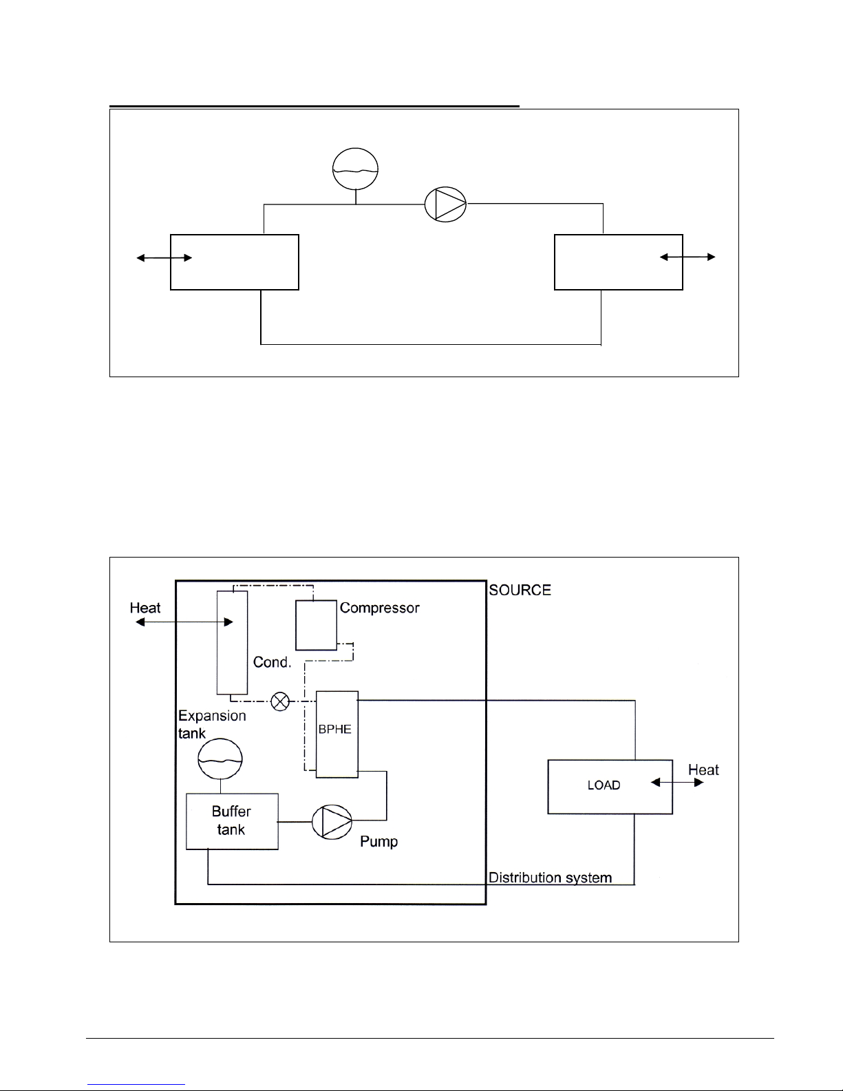
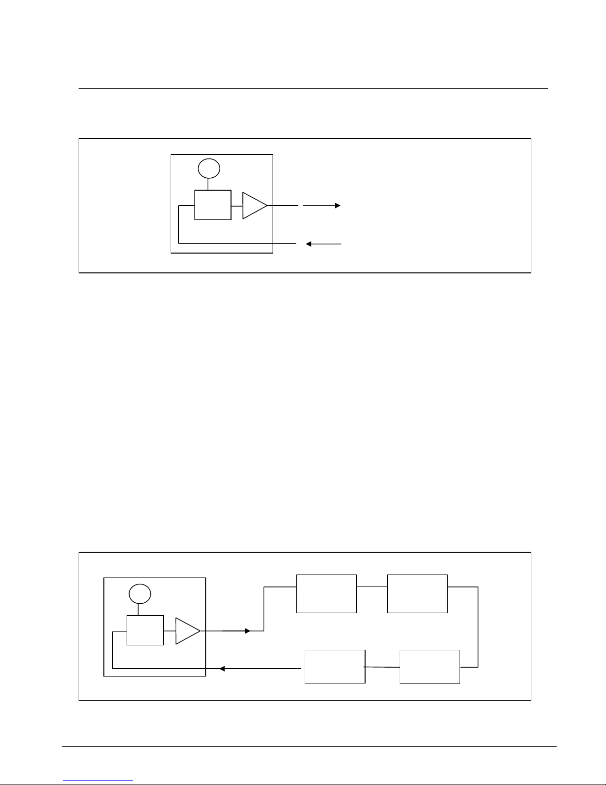
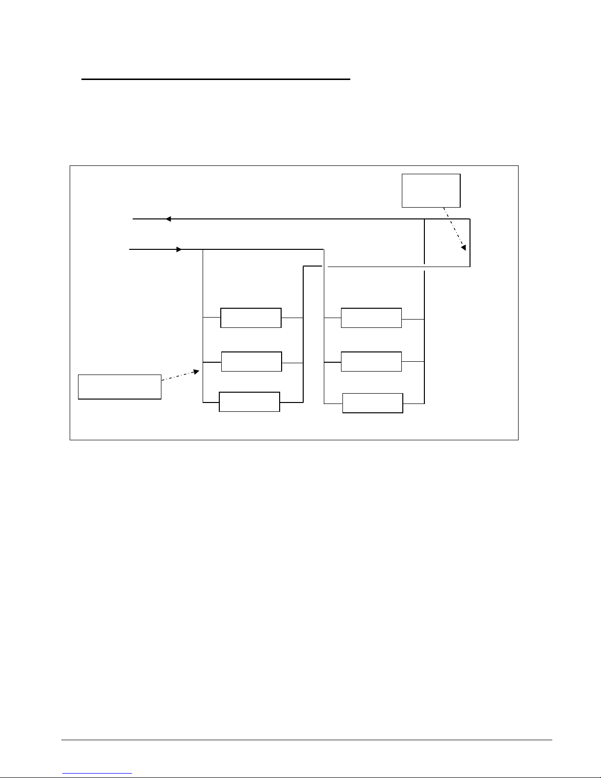
Schematic diagram of the basic close hydronic system:
Expansion
tank
Heat Pump Heat
Distribution system
SOURCE LOAD
In the mini chiller, the source will comprise of the refrigeration circuit, i.e. compressor, expansion
device, condenser and evaporator. A brazed plate heat exchanger (BPHE) is used as the
evaporator to produce the chilled water.
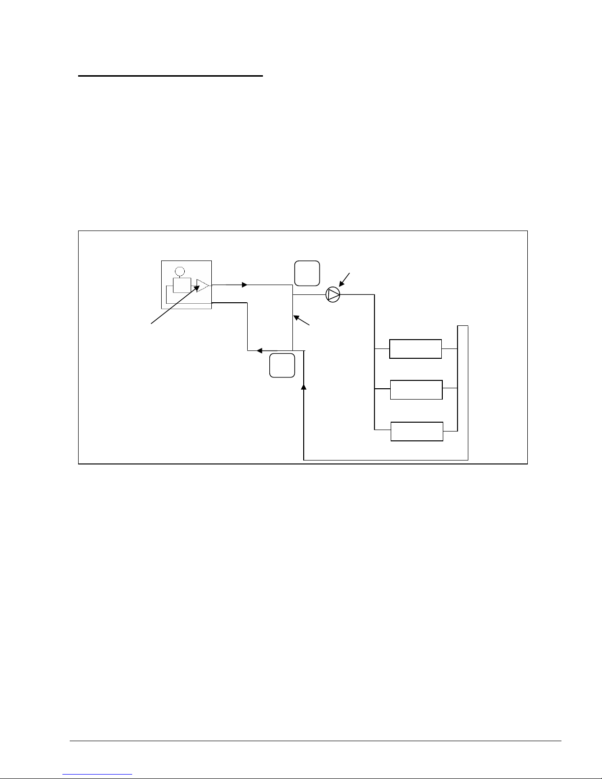
A built-in water tank is also provided in the mini chiller to act as a buffer storage. See next page.
For integration, both the expansion tank and pump are incorporated together into the mini chiller.
Hence, the schematic diagram of the system becomes as follows:
Introduction Page 2
Page 5

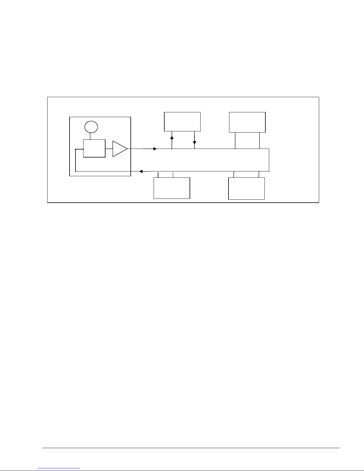
If both chilled water and hot water are required in the system, a mini chiller with a reverse
cycle operation will be used. The unit will have an additional 4-way valve and accumulator for
this purpose.
It is by such integration of components of the hydronic system that the mini chiller becomes
compact. Installation of the chiller will thus only involve:
1. The chiller mounting
2. Indoor fan coil unit installation
3. Water piping installation between the chiller and fan coil unit
4. Electrical wiring connection
This manual is written with the purpose of providing guidelines as to the installation and operation
of the hydronic system; i.e. both the chiller and fan coil unit. Application design guidelines will also
be discussed. Selection criteria of piping, valve, pump and other equipment are also given.
Examples of such complete installations are as shown in the following pages. This manual will
give some technical information and details on how such installations are designed and done
at site.
In general, there are three series of mini chillers available:
a) A series (from 30,000 Btu/hr [8.79 kW] to 50,000 Btu/hr [14.65 kW])
- double stack design, with built-in buffer tank
b) B series (from 75,000 Btu/hr [21.98 kW] to 125,000 Btu/hr [36.64 kW])
- double stack design, with built-in buffer tank
c) C series (from 80,000 Btu/hr [23.45 kW] to 150,000 Btu/hr [43.96 kW])
- monoblock design, without buffer tank
This manual must be used in conjunction with the Technical Manual and Installation and
Operation Manual (IOM) of the mini chillers and chilled water fan coil units.
Introduction Page 3
Page 6
Section 1: Chiller Mounting
Care must be taken to locate the air-cooled chiller at the proper place. Ensure sufficient
clearance around the unit to allow proper air flow and to facilitate access for maintenance.
Location of the units must also prevent short-circuiting of the discharge air. Do not block any air
passage in and out of the units.
Please refer to the corresponding Technical Manual for further information.
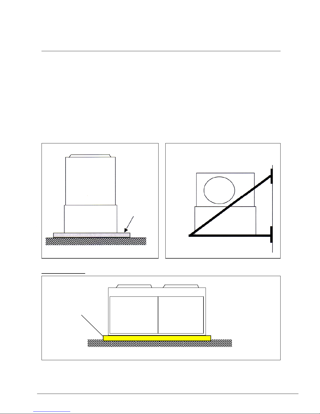
The chiller unit must be placed on a firm surface, e.g. concrete flooring, slab or plinth. Due
to space consideration, the chiller may be mounted onto a steel bracket which is secured to
a firm surface, e.g. brick wall, concrete wall or a steel structure.
concrete flooring
Series B Chiller
Plinth
Wall
Steel bracket
Plinth
Section 1 Page 4
Page 7

Such brackets must have sufficient strength to carry the weight of the chiller unit. It is
recommended that angle bars (e.g. 38mm*38mm*3mm
t
) or hollow section bars (e.g. 25mm*
50m*2mm
t
) to be used for fabricating these brackets.
These brackets must also allow clearance for removal of service panels for maintenance
purposes.
In any case, it is vital that the chiller unit is secured firmly onto the concrete floor/slab or steel
bracket by using studs, wall plugs or bolts/nuts at the four (4) mounting holes located at the base
plate of the chiller. The weight of the chiller unit and the water pipe connections are not sufficient
to prevent unit movement should any sudden impact or strong vibrations occur in the unit. Failure
to do so may cause the water pipes to deform and break.
It is further recommended that rubber isolation pads (1/2" thick) to be placed beneath each
mounting hole to prevent excessive vibration and noise. If necessary, isolating springs can
also be mounted.
The following pages are examples of these isolation pads and springs.
Section 1 Page 5
Page 8
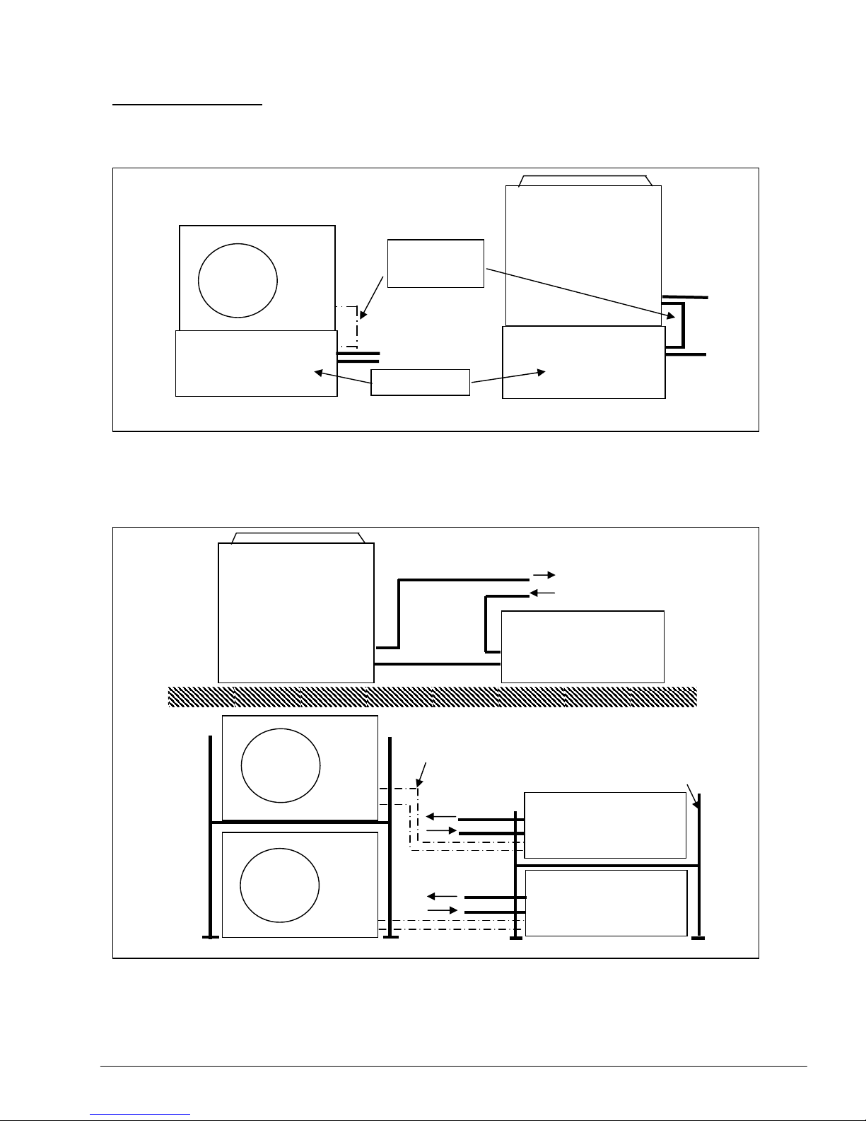
Special installation:
The A and B series mini chiller units have been designed with the refrigerant circuit located in the
top compartment and the hydraulic kit in the bottom compartment:
A-series B-series
Hydraulic kit
Piping
connection
Refrigerant
Water
B-series
A
-series
In some special installations whereby the available space (especially the height) is not
sufficient to install the chiller, it is possible to to detach these two compartments and install
them side by side. This is especially useful when there are multiple units which are stacked
together with a steel bracket.
Bracket
Hydraulic kit
Water
pip
es
Refrigerant pipe
connection
Hydraulic kit
Water pipes
Section 1 Page 6
Page 9
For the A-series type of mini chiller, the inter-connecting pipes between the two
compartments are the refrigerant pipes. For the B-series type, there is a water pipe in
between the two compartments.
Therefore, the detached installation of the A-series mini chillers is very similar to the
installation of a split type air-conditioning unit.
Note:
Gas line to be insulated with
tube insulation. Use the
correct size for each pipe, thickness
¼
”
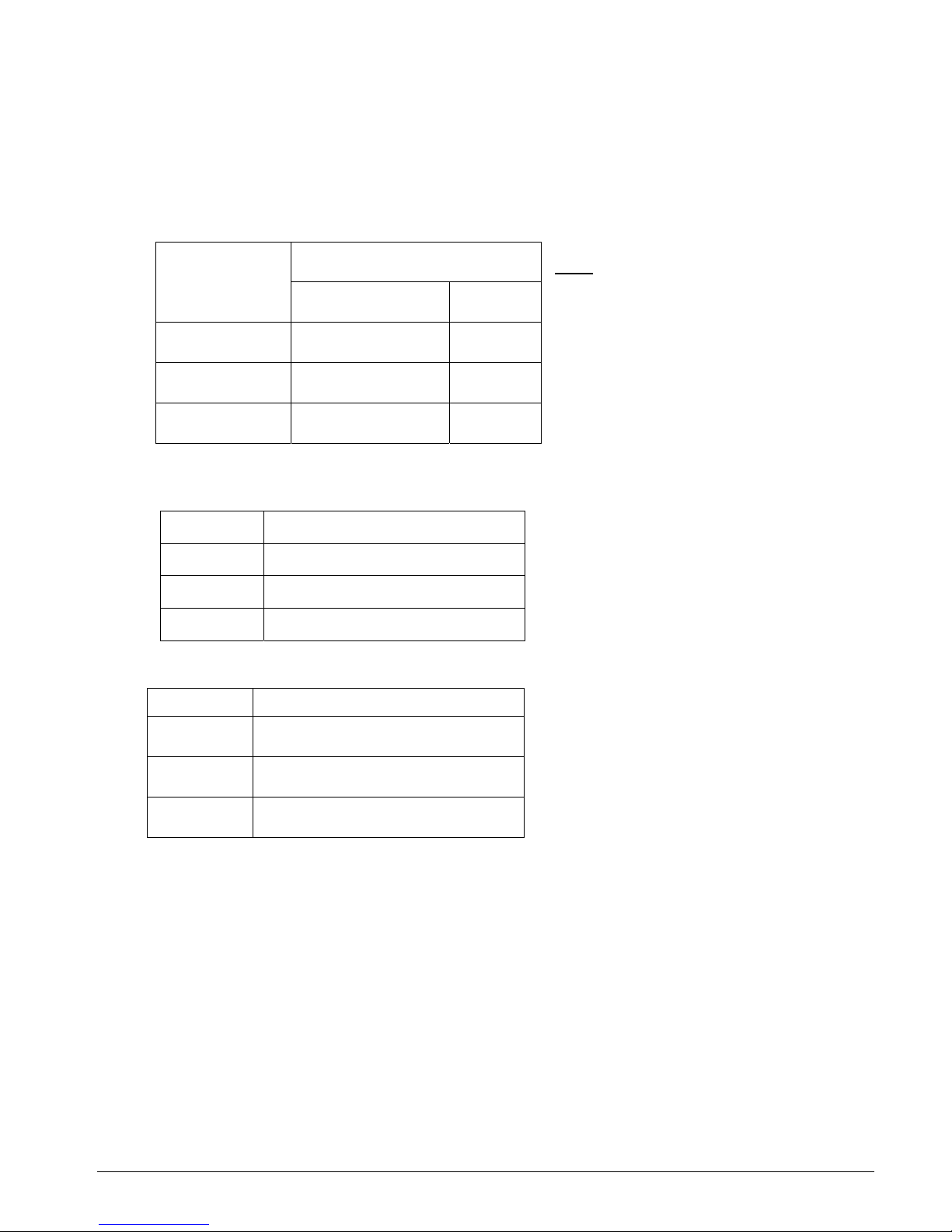
Refrig. Pipe size
Liquid Gas
AC 040A
3/8” ¾”
AC 050A
3/8” ¾”
AC 058A
½” ¾”
Take care of the following items [for detached A-series installations]:
Maximum pipe length,m
AC 040C
20
AC 050C
20
AC 058C
20
a) Do not allow excessive refrigerant pipe
length between the two compartments.
Always choose the shortest path.
Long piping will cause high pressure
drops and reduces the capacity of the
system. Use the following
recommendations:
Maximum elevation, m
AC 040A
10
AC 050A
10
AC 058A
10
b) It is possible to have the hydraulic kit
higher or lower than the refrigerant
compartment. Do not allow excessive
elevation between these two
compartments. Use the following
recommendations:
If the elevation exceeds the above recommendations, care must be taken to ensure sufficient oil
return to the compressor. Use oil traps (one every 30ft height interval) or oil separators, if
necessary.
c) The longer pipe lengths will require more refrigerant charge for optimum
performance.
Recommendation: Additional 50g (R-22) for every 1 meter of connecting pipe length.
Similarly, additional refrigerant oil charge may be required.
Section 1 Page 7
Page 10

d) Use as few bends as possible in the pipe run. Each bend will cause extra pressure drop and
reduces the capacity of the system. Do not use more than 10 bends. For both A and B series chillers, locating the hydraulic kit at a far distance will also mean having a longer
water pipe length. This will incur a higher pressure head to the water pump in the chiller
unit. If not careful, this will reduce the water flow rate through the system and may cause
system failure, e.g. water freezing, compressor tripping.
Furthermore, the longer pipe will increase the cost of installation.
Always look for the closest possible locations for these two compartments.
External drain pan
In some instances, it is necessary to install an external drain pan beneath the unit to collect
any condensate water from the chiller unit. This is especially so for the heat pump versions
,where water will condense on the heat exchanger coil during the heating mode. Further more,
a lot of water will flow out during the defrost cycle.
Such external drain pans are needed when the chiller units are installed inside a plant
room where it is not appropriate for the floor to be wet. (Note A)
It is recommended that the drain pan to be fabricated out of galvanised iron (GI) sheet
metal, at least 0.8 mm in thickness. Allow the drain pan depth of about 20mm.
This external drain pan should be laid out on the floor first before placing the entire chiller
unit on top of it. It is recommended that the chiller unit to be raised up by 20 - 30mm from
the drain pan so as to prevent rusting of the chiller base pan.
Note A: Caution! Please ensure adequate ventilation in the plant room else the
chiller unit may trip.
Section 1 Page 8
Page 11
Section 2: Water Pipe Circuit
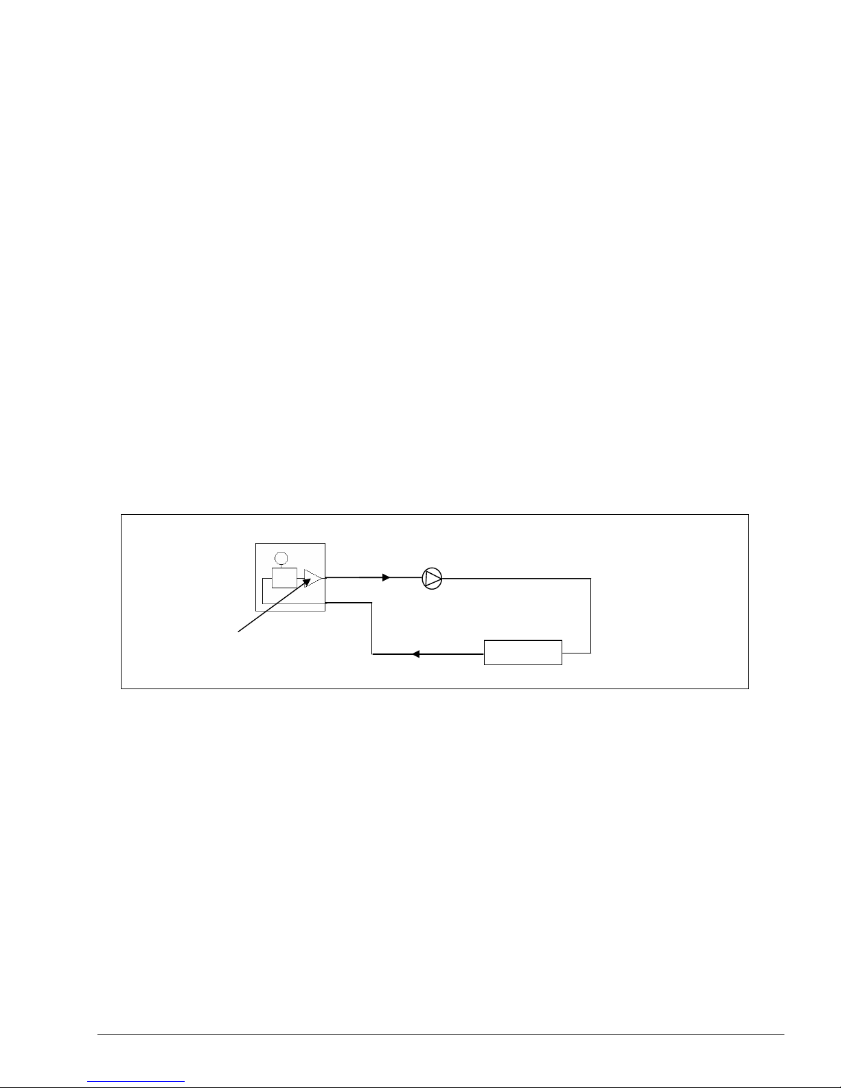
We have seen that the mini chiller has an integrated buffer storage tank, expansion tank and
water pump together as one unit. Henceforth, we will represent the unit as such:
MINI CHILLER UNIT
In this section, we will look at the various piping circuits which we can use to connect the chiller
unit with the load fan coil units.
There are many different piping circuit configurations which can be used, depending on:
a) the geometry of the building
b) the available space for installation (e.g. the dimensions of the plant room)
c) the economics of installation
d) loading capability requirements
The general rule of thumb in designing and determining the piping circuit network is:
KEEP IT SIMPLE!
The more extensive a pipe network is, the more complex it is and it becomes more difficult to
analyse and control.
In general, there are 4 types of this pipe configuration:
1. Series
2. Diverting
3. Parallel direct return
4. Parallel reverse return
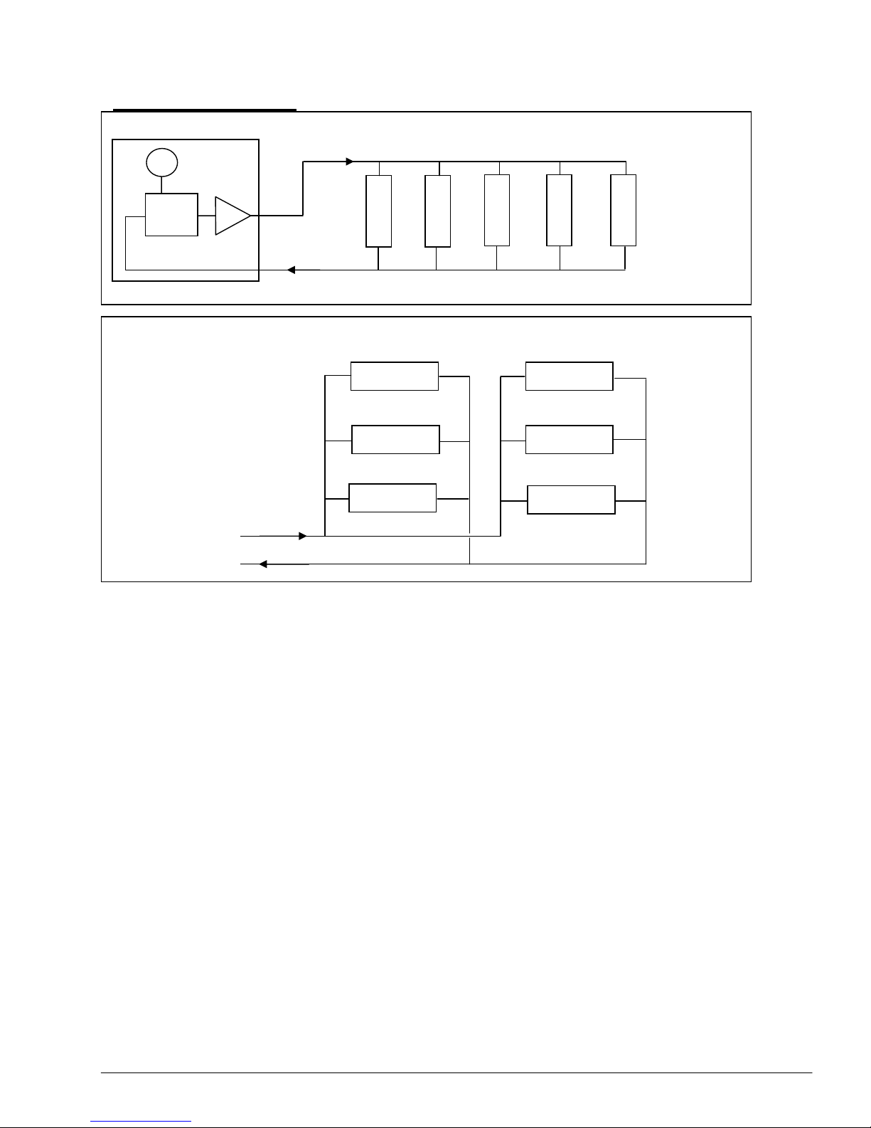
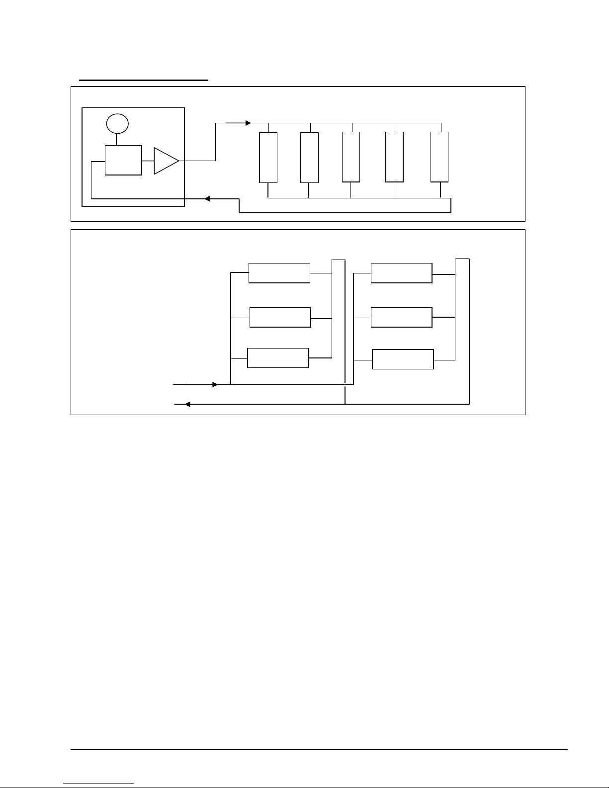
Series Circuit:
Note: For C-series, the buffer tank is not
applicable but the fundamentals of water piping
circuitry is still the same
Water out
Water in
LOAD
FCU 1
LOAD
FCU 4
LOAD
FCU 3
LOAD
FCU 2
Section 2 Page 9
Page 12
Advantages:
i. Lower piping cost
ii. High water temperature drops
Disadvantages:
i. Each fan coil loading cannot be controlled separately
Diverting Circuit:
LOAD
FCU 3
LOAD
FCU 1
LOAD
FCU 2
LOAD
FCU 4
Advantages:
i. Allows individual control to each fan coil unit
Disadvantages:
i. Only fan coil units with low pressure drops can be used
ii. Due to low water velocity in each fan coil, an air vent is required for
each fan coil
iii. Higher installation cost
iv. Water entering temperature for each fan coil is different, i.e. it gets
higher further away from the source
However, both the series and diverting circuits are seldom used in hydronic systems. The
more commonly used are the parallel circuits because they allow the same water
temperature to be available to all fan coil units.
It is recommended that the parallel circuits to be used in the installation of the mini chillers
with the fan coil units.
Section 2 Page 10
Page 13
Parallel Direct Return
Vertical installation
Fan coil
unit
Horizontal installation
The basis for the design is "First In - First Out".
In this system, the length of supply and return piping for each fan coil is unequal. This will
affect the water flow rate through each individual load. Proper balancing is required to
provide adequate water flow rate for each fan coil.
Nevertheless, the cost of installation is lower compared with the reverse return configuration
due to the shorter pipe length needed. Therefore, this method is more economical for
installation of fan coils with different pressure drops and balancing valves are used.
This method is also suitable for open system applications whereby the return from the
fan coil loads are discharged into a external tank.
Section 2 Page 11
Page 14
Parallel Reverse Return
Horizontal Installation
Fan coil
unit
V
ertical Installation
The basis for the design is "First In - Last Out".
In this installation, the supply and return water pipes or of nearly equal lengths. Thus, it seldom
requires balancing of water flow rate for individual fan coil unit. If required, this balancing will be
easier.
This method is recommended if all the fan coil units have the same or nearly the same
pressure drops.
Another advantage of this reverse return system is a reduction of the working pressure drop
across any balancing valves used for the fan coil units.
However, such a system is not recommended for high-rise buildings because of the vertical
weight of the extra piping required. In such instances, it may be more practical to use direct
return systems.
The extra piping also does not give any advantage in open system applications because the
same atmospheric conditions exist at all open points of the system.
Section 2 Page 12
Page 15
Parallel Reverse Return Header, Direct Supply Rise
This is a variation of both the direct and reverse return systems, whereby it is not feasible to
have a full reverse return piping.
Instead, only the return header is in reverse, whereas the supply to the individual fan coils are in
direct configuration.
direct supply
reverse
return
This method will have the advantage of lower installation cost with some benefits of a better
water balanced system.
Balancing valves are required for each fan coil unit for proper flow balancing.
Section 2 Page 13
Page 16

Close System vs. Open System
The mini chiller has been designed with an application for a close water piping system.
However, it is still possible to use the unit with an open system by means of an additional
buffer tank.
In such a system, the chiller will discharge the chilled water into the tank while a secondary
external pump will then pump the water to the fan coil units.
It is recommended that the tank to have a baffle plate in between to isolate the two return
water from the chiller and fan coil load. This will prevent the hotter return water temperature
from the load mixing with the cold chilled water from the chiller.
Such a method is suitable for:
- multiple chillers operation
- multiple secondary pumps supplying chilled water to several zones
The water volume in the tank can also be sized to act as a storage to provide cold water to the fan
coil units. By doing so, the chiller may be cycled-off for longer periods of time, hence saving energy
costs.
However, since this is an open system, there is a higher chance of air entering the water.
Care must also be taken to ensure there are no leakages along the pump suction line else
air will enter the system. The air will be drawn into the buffer tank and accumulate there. This
may affect the water flow rate and trip the chiller unit. Always ensure the automatic air vent
on the buffer tank is operating properly to release any trapped air.
Supply to load
Return from load
Tank
Chiller Secondary pump
Check if this air
vent is OK or not!!
Buffer tank
*** See Page 25 for more information
Section 2 Page 14
Page 17
Primary - Secondary Pump System
There may be instances when the integrated pump in the mini chiller is not able to deliver the
required head pressure to the load in a close piping system.
To overcome this problem:
1. Change the water pump with a higher head pressure capability.
Please consult with the factory as to the requirements. Calculate the required
head pressure and select suitable replacement pump.
2. Install a booster pump.
It is recommended that this booster pump to be installed as a primary - secondary
system; as follows:
A
B
Primary pump in
chiller unit
Secondary booster pump
Bypass loop
Load
More than one secondary pumps can be installed together, e.g to serve several zones.
There are two drawbacks to this system:
a) Cost - additional two or more pumps are required
b) The bypass chilled water is sent back to the chiller unused
Keep the bypass loop as short and large as practical possible. Do not put any valve in
this loop. This is to minimise the pressure loss between the entry and exit points of the
loop.
However, this length must be sufficient to prevent recirculation turbulence.
Section 2 Page 15
Page 18
The temperature of water entering the load will depend very much on the sizing of the
secondary pump.
1. If the capacity of primary pump = secondary pump, there will be no flow in the bypass
loop. Hence, the water temperature entering the load will be equal to the water
temperature leaving the chiller.
2. If the capacity of primary pump > secondary pump, there will be a nett flow down the
loop and returned to the chiller unused. Therefore, tee A becomes a diverging tee and
tee B becomes a mixing tee. The water temperature entering the load will also be equal
to the water temperature leaving the chiller. However, the water temperature entering
the chiller will be colder due to mixing of the unused chilled water at tee B.
3. If the capacity of primary pump < secondary pump, there will be a nett flow up the loop
from B to A. Thus, tee A becomes a mixing tee and tee B becomes a diverging tee.
Then, the water temperature entering the load will be in between the water temperature
leaving the chiller and the water temperature entering the chiller.
There may be installations using pumps in series to boost the head pressure.
But this is not recommended due to a high chance of wrong pump sizing which can
cause damage to the pumps themselves.
Primary pump
Secondary pump in series
Load
For this to work properly, both the primary and secondary pumps must be of the
same capacity. Else, the greater capacity pump will overflow the lesser pump and
cause:
a. Cavitation problems to the lesser pump.
b. Excessive pressure drops across the pump itself.
c. The extra head pressure build-up may cause damage to some of the
components in the chiller itself.
Section 2 Page 16
Page 19
Multiple Chiller Installation
In most cases, one single chiller will not be sufficient to provide the cooling load of a system.
Several chillers must be combined together to give the required loading.
Generally, these chillers will be installed together in parallel. There are several ways to do
this:
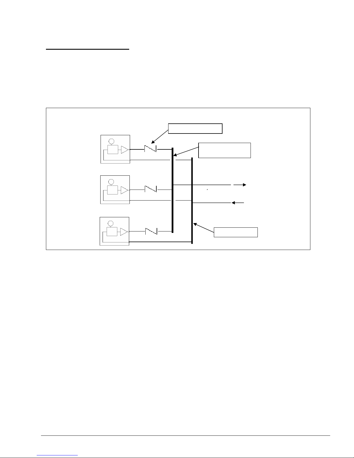
1) Common Supply and Return Headers
Check valve
CHILLER 3
CHILLER 2
CHILLER 1
Chiller water return
Chilled water supply
Supply header
R
etu
rn h
eade
r
This method is most preferred and commonly used because of the lower cost and ease
of installation.
Each chiller is normally set at different return water temperature to facilitate load staging.
As the temperature becomes colder, the chillers will switch off one by one.
Generally, the header pipe size is larger than the supply and return pipes, e.g. one or two
size larger. This is to have a low pressure drop along the header. Check valves are usually
located along each chiller supply pipe to prevent back flush of water once the chiller is
switched off. Such back flow may damage the water pump.
However, this method has several drawbacks:
a) Proper balancing of the water flow rate through each chiller is crucial.
b) If any one chiller is off, the water flow to the load will be affected. So much so
that during low load conditions, when the return water temperature is cold, and
all the chillers have cycled off, no water will be pumped to the load. To
overcome this problem, it is necessary to wire the chiller controls for continuous
pump running as long as one fan coil unit is in operation. See Section 11.
Section 2 Page 17
Page 20
c) Since all the water is pumped into one supply line, there is less flexibility in zoning
the water distribution. The pump head may not be sufficient to deliver water to
zones of high pressure losses, e.g. at the furthest end of the pipe system.
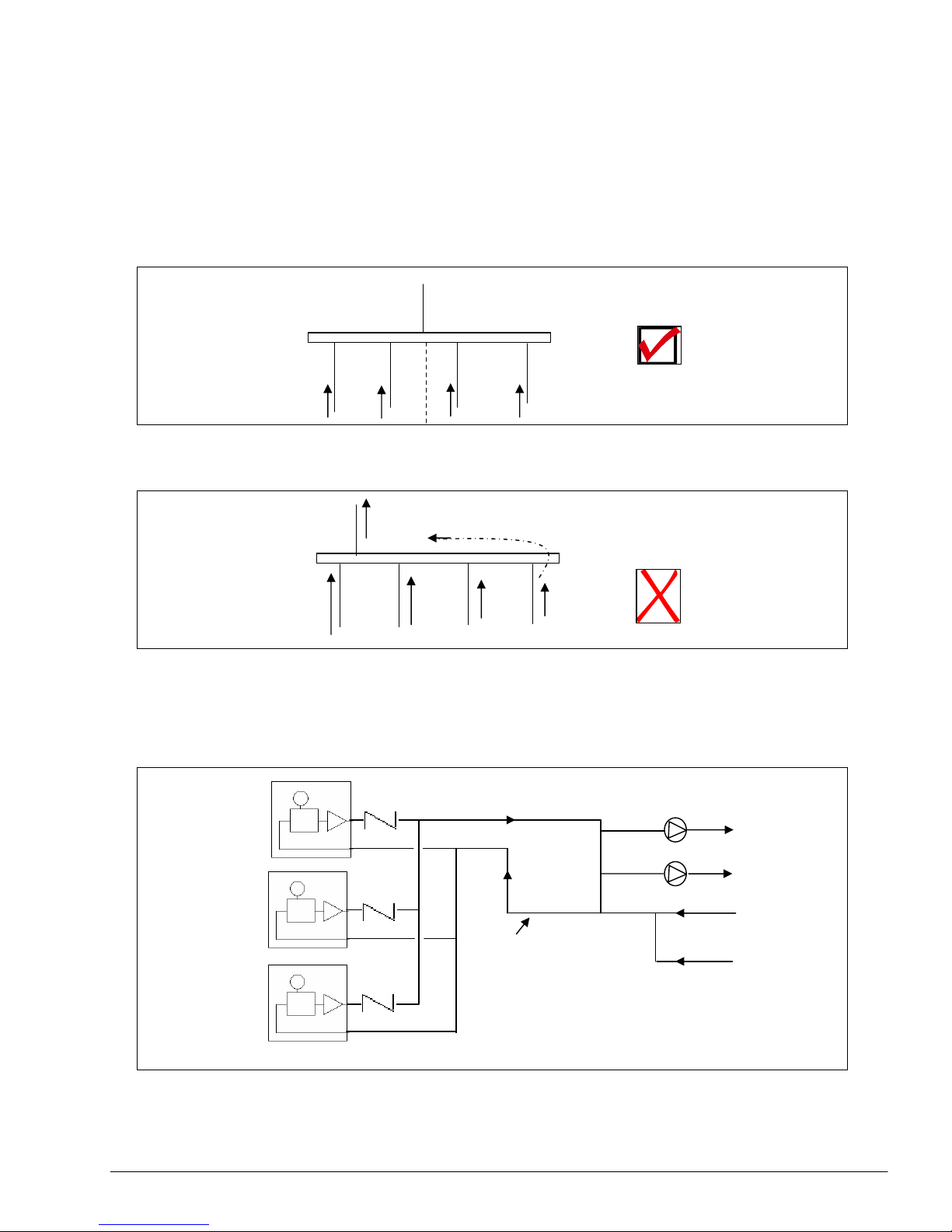
Because of the importance of water flow balancing among all the parallel chillers,
the design of the header is very important.
Place the common pipe near the center of the header pipe. This will help to balance
the water distribution between the left and right sides of the header.
If the common pipe is at one end of the header, water from the branches at the
other end of the header will find more difficulty to flow into the common pipe.
Balancing valves must be installed at each supply branch to ensure adequate
water flow rate through each chiller unit.
2) Primary-Secondary System
header
Water will experience a higher
Resistance to flow to common pipe
From the furthest branches.
Secondary pumps
To load
Return from load
Bypass loop
CHILLER 1
CHILLER 2
CHILLER 3
Section 2 Page 18
Page 21
In this method, the load side of the system is isolated from the chiller side. Chillers of different
capacities can be installed together without much balancing problems and effect on the supply
flow rate to the loading. It just requires individual balancing of the flow rate through each chiller by
using the balancing valves. Check valves and balancing valves are recommended to be installed
for each chiller supply pipe.
The secondary pump alone will handle the flow and pressure requirements of the loads.
Because of this secondary pump, the sequencing of the chillers will not affect the
water supply to the load when any of the primary pumps switches off. Several secondary
pumps can also be installed to the bypass loop to serve several zones. This creates
flexibility of installation.
The only drawback to this method is cost. The piping network is more extensive and
additional water pumps are required.
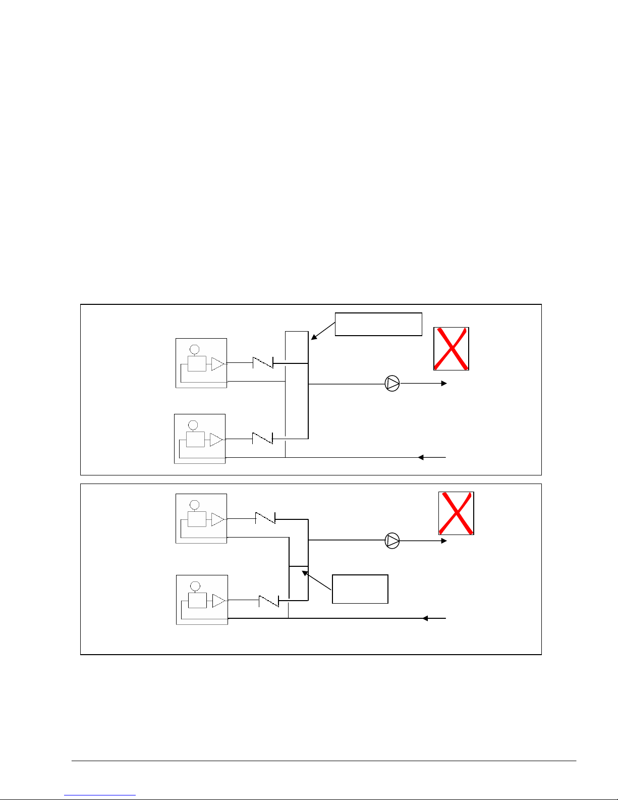
It is important that the bypass loop is located correctly. The following two are questionable
variations to the above method:
By pass loop
By pass
[A]
[B]
Secondary pump
Secondary pump
To load
To load
Return from load
Return from load
Section 2 Page 19
Page 22
For both method [A] and [B], the return water temperature for the multiple chillers will not be the
same due to mixing. This will cause inefficiencies and energy wastages to the chiller operation.
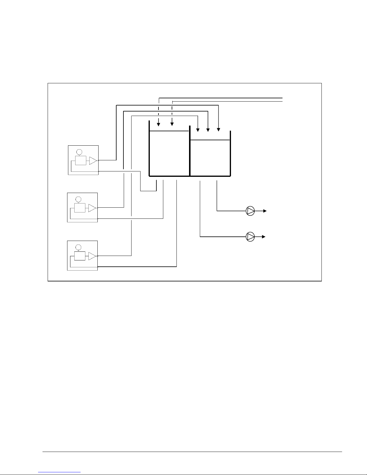
3) Common Tank System
This method is for an open system.
CHILLERS
to load
Tank
return from load
As seen from the diagram, each chiller and secondary pump forms its own individual pipe
circuit. There is no cross flow among each of them. This has been achieved with the
common tank which acts as a buffer storage tank.
Therefore, there is no need of check valves. Normal globe valves will suffice to ensure
proper water flow through each chiller.
Usually, the tank is at a higher elevated position, to allow gravity feed of water to the chillers
and pumps.
This method is most expansive to install due to the additional piping and tank required for
the system.
Please refer to Page 14 for cautions during installation and operation.
Section 2 Page 20
Page 23
4) In some instances, variation to method (1) have been used whereby common
headers are NOT installed to the multiple chillers. Instead, the chillers are connected
together with one supply and return pipe only.
This method is still possible but there will be higher pressure drops along the common
pipe lines. It is recommended that a larger pipe size to be used along this common line
to reduce the friction losses.
Water flow rate tends to be faster at the tee nearest to the main supply lines due to
lower friction. Therefore, proper balancing to ensure sufficient distribution to each
chiller is vital.
A First In - Last Out arrangement between the supply and return lines may be
useful to reduce the problem of distribution.
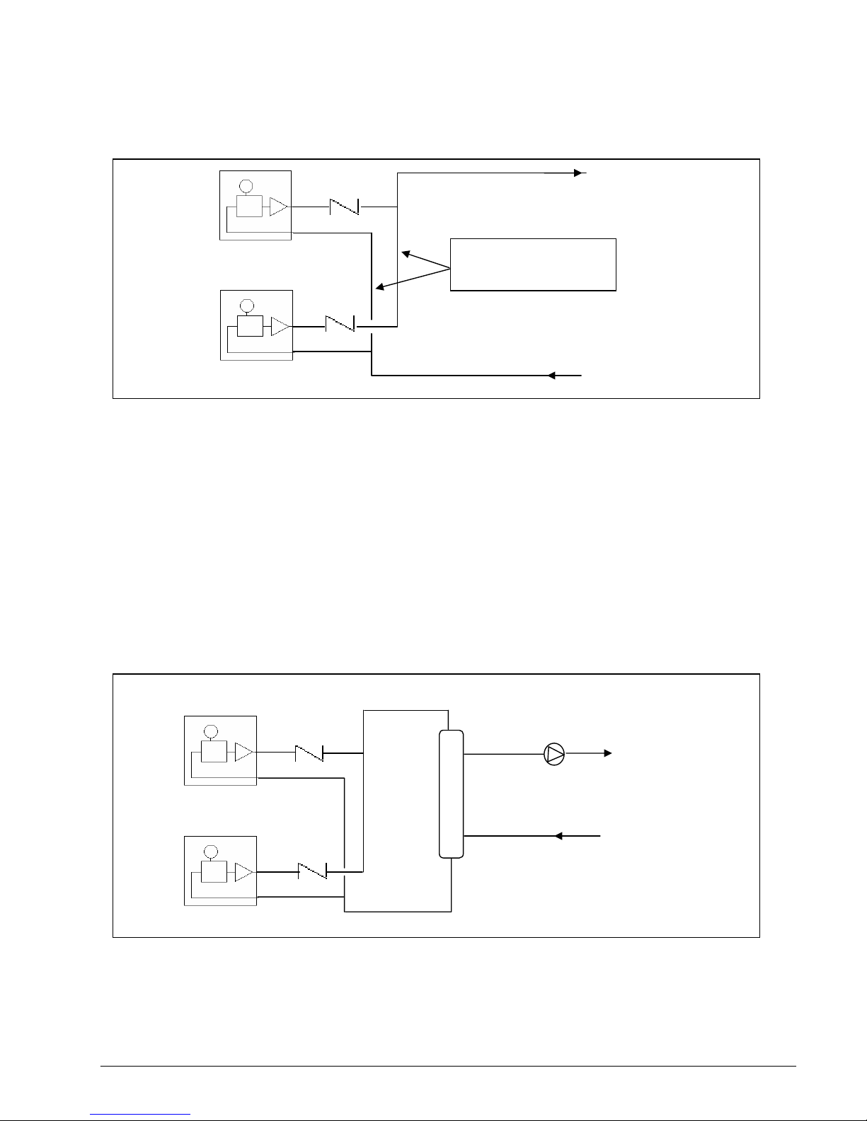
5) Another variation to the primary-secondary system mentioned in (2) above, is to use
an auxillary tank to replace the by-pass loop. By using this tank, we can ensure a
minimal pressure drop between the entry tee and exit tee of the secondary circuit.
This is not a common
header pipe
To load
Return from load
To load
Return from load
A
uxiliary tank
Section 2 Page 21
Page 24
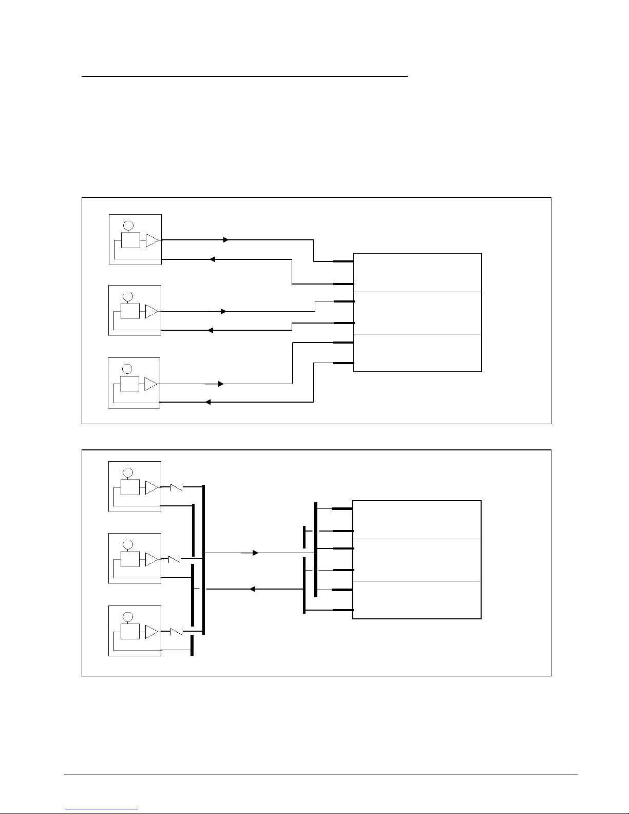
Multiple Chiller, Single Fan Coil Load With Multiple Circuits
There are instances where several chillers are used to supply the chilled water to a large
single fan coil unit. Each chiller will serve one of the multiple circuits of the heat exchanger coil
in the fan coil unit.
There are two ways to install the pipe circuits for this system:
a) Individual Circuiting
b) Common Header
CIRCUIT 1
CIRCUIT 2
CIRCUIT 3
CHILLER 1
CHILLER 2
CHILLER 3
CIRCUIT 1
CIRCUIT 2
Section 2 Page 22
Page 25

The first method has more extensive pipe works. But the water side flow control is
easier and there is less pressure drop. Globe valves may be needed to ensure
sufficient flow rate. Check valves are not required.
Due to the header pipes in the second method, check valves are needed for each
chiller. Globe valves or balancing valves are also needed for each chiller for water
balancing. All the pumps will operate in parallel and a higher water pressure drop is
expected. Furthermore, balancing valves are also required in each circuit of the fan
coil unit for proper balancing of the entire coil.
Nevertheless, if any one of the chiller is OFF, the second method will always allow an
even water distribution to the whole heat exchanger in the fan coil unit. In the first
method, hot air will by-pass through the portion of the coil which the chiller is OFF.
Section 2 Page 23
Page 26

Make Up Water Supply
The make up water supply is used to refill water back into the hydronic system in the event of:
a) Leakage in the system
b) Maintenance service
The supply is usually from the main domestic pipe and it is usually connected to the water return
pipe of the pump; due to the lower pressure which will assist in "sucking" in the water. However,
should the pressure in the main supply pipe is lower than the pressure in the return pipe, water will
not enter the system. Rather, switch off the pump and allow the mains pressure to fill the system.
In view of this, it is necessary to install a check valve along the make up supply pipe to
prevent back flow out of the system.
Other equipment which can be installed (optional) along the make up supply pipe:
a) Pressure gauge
b) Safety relief valve - to prevent over filling [see Section 10]
c) Pressure regulating valve
d) Filter element [see Section 9]
e) Water meter
Domestic water supply
Pressure gauge
Check valve
CHILLER
Return
Section 2 Page 24
Page 27

Loop Piping Installation
One of the main advantages of using mini chillers is the ability to have long water piping
installations. However, it is important to check that the water pump head pressure capability is
adequate to pump the water through the pipe network. The longer the pipe length is, the higher
is the pressure drop. If the pump head is insufficient, it may be necessary to change the water
pump itself. See Section 5.
With such installations, it is also important to check the condition of the automatic air vent valve.
A high pressure drop along such pipe network may result in the return water to have a negative
pressure (i.e. suction vacuum pressure in the buffer tank). Due to the mechanism of the air vent,
air will be drawn into the buffer tank itself! This in turn will cause the pump to be air-locked. A
symptom of such condition is that air will always be purged out of the tank when we manually
open the air vent.
The solution to this problem is to remove the automatic air vent and plug up the hole. Make
sure that all the air trapped are purged out of the system before plugging it. This can be done
by continuously filling up the system with water until no air bubbles comes out of the hole.
Section2 Page 25
Page 28

Water Pipe Connections
All mini chiller units comes with ∅1-1/4” pipe connections.
1] A-Series
The pipe connections are on the right-hand side of the unit (when facing the fan blade).
2] B-Series
The pipe connections are on the same side as the control box compartment
Water inlet
Water outlet
Water inlet
Water outlet
Section 2 Page 26
Page 29
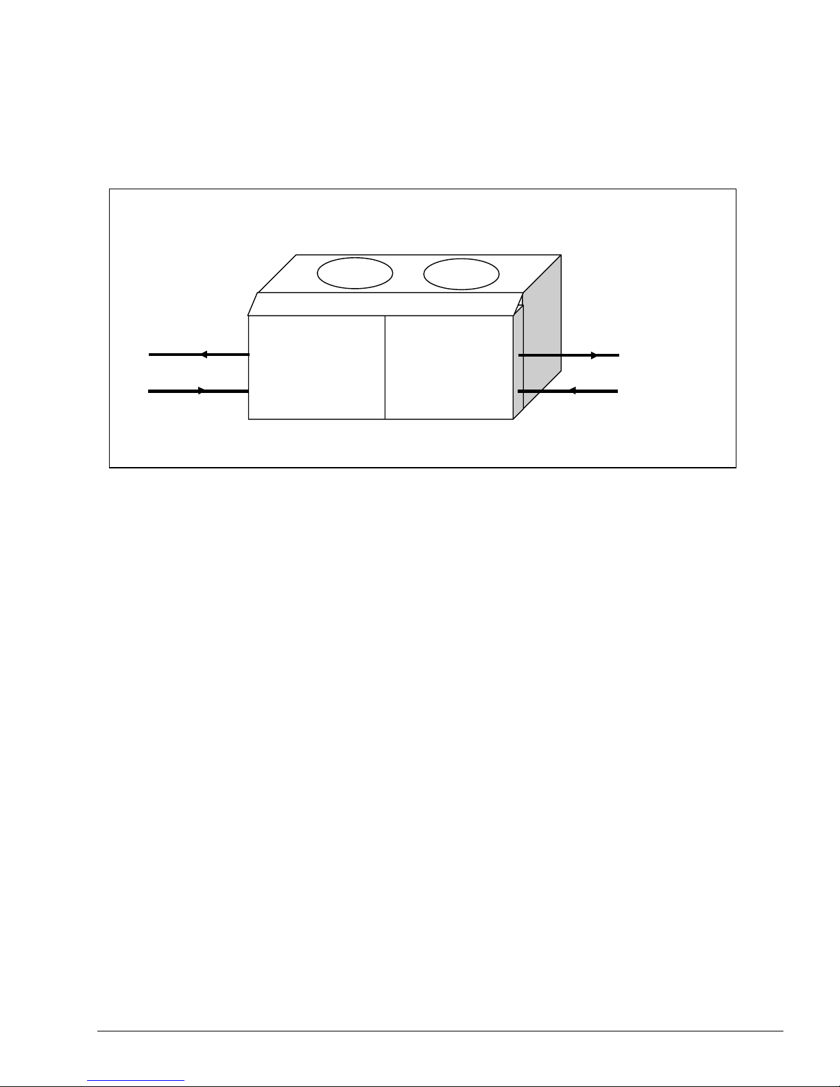
3] C-Series
The pipes can be connected either from the left or right side of the unit (with
respect to the compartment doors).
Water inlet
Water outlet
Section 2 Page 27
Page 30

Section 3: Water Pipe and Fittings
There are several types of pipe we can use for the water piping:
1. Black carbon steel pipe
2. Copper pipe
3. PVC pipe
Do not use galvanised iron (GI) steel pipe! This is because the zinc coating on the GI pipe will
have an electrolytic reaction with the copper components of the system, e.g. the brazed plate heat
exchanger and fan coil unit heat exchanger.
The zinc will be the sacrificial metal and deposit itself on the copper surfaces.
a) The pipe wall thickness will slowly eat away and cause leakages
b) The zinc deposit on the copper surfaces will retard heat transfer process. It may also
reduce the gap between plates in the BPHE and slows the water flow rate.
The mini chiller water piping connections is for a pipe size of 1-1/4". For a single run installation,
the recommended maximum pipe length is 150 meters, but this will depend very much on the
method of installation and the fittings used. The more complex the piping network is and the more
fittings there are, the higher will be the friction losses. This will limit the piping length available.
Always calculate the friction losses in the system and compare this with the capability of the water
pump in the chiller unit. See Section 4
1. Black Steel Pipes
The black steel pipes are the most commonly used in chiller installations. It is relatively cheap and
by far the strongest among the 3 types mentioned above.
However, these pipes are heavier and requires more extensive work to join and install.
The common pipe sizes are determined from the ASME (American Society of Mechanical
Engineers) standard B36.1 OM which specifies the pipe dimensions. See Appendix 1.
Generally, steel pipes are sold in lengths of 6 meters each. The dimensions of importance which
we need to know is the nominal pipe size (NIPS) and schedule number (wall thickness).
For pipes 14" (350mm) and larger, the nominal diameter is the same as the actual outside
diameter.
For pipes between 3" (80mm) to 12" (300mm), the nominal diameter is close to the actual inside
diameter.
However, for pipes smaller than that, the nominal value does not correspond to any actual
dimension.
Steel pipes are manufactured with different wall thickness. The ASME standard has defined
schedule numbers to identify these specifications. A pipe with a nominal pipe size may have
several schedule numbers. See also Appendix 1
Section 3 Page 28
Page 31

Therefore, pipes may have the same nominal diameters (outside diameters) but with different
inside diameters because of the different schedule numbers.
The usual schedule numbers are 10, 20, 30, 40, 60, 80, 100, 120, 140 and 160 with the thickness
increasing with the numbers.
These numbers are further classified as Standard (ST), Extra Strong (XS) and Double Extra
Strong (XXS) whereby applications requiring higher pressures will need pipes with thicker walls.
However, in the HVAC industry and for our mini chiller installation, a standard schedule 40 pipe
will suffice.
The steel pipes may be joined by several methods:
1. Arc welding
2. Thread (usually up to 50mm) with PTFE Teflon white tape
3. Flange with gaskets
2. Copper Pipes
Copper pipes are chosen for water piping because of their resistance to corrosion and ease of
installation. The pipes are light and ductile.
However, the cost of these pipes are higher compared with steel pipes (generally by 3 5 times).
The sizes of these copper pipes are defined by the ASTM (American Society for Testing and
Materials) standard B88 for water and drain services. See Appendix 2.
There is also another ASTM standard B280 which specifies the sizes of pipes used for
refrigeration services with different wall thickness. This standard uses the outside diameter as
the nominal size.
These pipes are also generally sold in lengths of 6 meters.
Generally, the B88 standard defines 4 types of copper tubes: Type K, L, M and DMV with
descending wall thickness. The most commonly used types are type L and M which have higher
internal working pressures. These may be of hard drawn or soft annealed temper.
The copper pipes may be joined by:
1. Brazing
2. Soldering
3. Flare joint / compression joint fittings
Section: 3 Page 29
Page 32

3. PVC Pipes
The plastic PVC (polyvinyl chloride) pipes are light, generally inexpensive and corrosion resistant.
The pipes also have a very low friction factor (i.e. with smooth surface) which results in lower
pumping power and smaller pipe sizes. However, these pipes are not suitable for high
temperature applications as they losses strength rapidly at temperatures above ambient. The
pipes also have high coefficient of expansion, i.e. at high temperatures any pipe joint made may
become loose and leaks. Because of the weaker strength of the material, such pipes must be
installed with shorter support spans.
As a result of the above mentioned disadvantages, it is not recommended for PVC pipes to be
used for external applications, especially under direct exposure to sunshine. They may be
suitable for piping water indoors, e.g. under ceiling spaces, attics, plant rooms, etc.
The PVC material is classified as a thermoplastic. Generally, there are two types:
1. U-PVC (unplasticized PVC): for general usage up to 60°C
2. C-PVC (chlorinated PVC): for higher temperature applications.
The PVC pipes and fittings used inside the mini chiller unit (factory assembled) are of DIN
8061/8062 standard. Therefore, use back pipes and fittings with the same standard when running
pipes from the chiller to the fan coil units. It is recommended that pipes with pressure rating of
PN16 (16 bar working pressure) to be used. See Appendix 3.
Do not use PVC pipes manufactured to other standard specifications, e.g. BS 3505/3506
as the fittings will not match with those used in the chiller. The pipe wall thicknesses are also
different.
The usual method of joining the pipes and fittings is with solvent cementing/welding. Some fittings
also have threads for joining purposes (with PTFE white tape).
It is recommended that 'IPS Weld-on PVC 717' solvent cement to be used. It is gray in
colour and used for heavy-body applications.
The following are some guidelines to ensure that the solvent cement joint is done properly:
a. Cut the pipe square and deburr. Clean and dry surfaces before coating the cement.
b. Apply a full, even layer of cement equal to the depth of the socket. Avoid excess and
puddling.
c. Assemble while the cement is wet. If not wet, recoat parts.
d. Ensure pipe fits snugly into socket. Give a twist of 1/8 to 1/4 turn.
e. Hold for 30 seconds to prevent push out and allow for initial set. Wipe off excess.
f. Allow curing time at least 5 minutes, up to 30 minutes. Longer curing time is better for
higher pressure/temperature applications.
Section: 3 Page 30
Page 33

Typical Pipe Fittings
The following are typical pipe fittings used for installing the mini chillers. Note that the pipe
fitting size of the chiller itself is 1-1/4".
a) Steel Pipe
Because of the pipe fitting size, it is recommended that the connecting pipes and fittings
to be joined with thread. However, where necessary, fittings for weld joining may also be
used.
The following standards are applicable for these fittings:
ASME B16.9, ASME B16.11, ASME B16.28 and ASME B1.20.1
Internal
thread
Tee joint
Internal
thread
90º elbow
Internal
Page 31 Section 3
thread
Reducer
45º elbow are also available
but not commonly used, unless
necessary
A tee joint can either be a flow
mixing or flow diverging point,
depending on the design of the
pipe work.
Some reduces/ fittings do not
have these ribs: used for better
gripping when tightening with
pipe wrench.
Page 34

Section: 3 Page 32
with reducing ends
Nipples are usually used
for joining different types
of fittings, e.g. an elbow
with a reducer.
ni
pp
le
External
thread
connector
Used for joining two
lengths of pipes
together
Internal
thread
Union/ coupling
Used for joining two
lengths of pipes
together
Made up of two halves,
each screwed into a
pipe end.
Both are then joined
with a locking nut in
between
Page 35

flange
connector flange
holes for bolt and
nut
nipple
gasket to be placed on the mating
surfaces of both flanges
This method is not recommended for the small pipe size used for the mini chiller.
** The fittings for weld joining are very similar to those mentioned above, i.e. they do
not come with the thread portion. They may be butt-welded or socket-welded.
BUTT
SOCKET
Section: 3 Page 33
Page 36

b) Copper Pipe
The most commonly used method of joining copper pipes is brazing with an oxy-acetylene
flame and copper filler rods. For this purpose, one end of the pipe is expanded by using
an expander tooling, and the end of the other pipe is inserted into the expanded end. The
joint is then brazed together. [see Appendix 4 for expansion dimensions]
Similarly, fittings are available for such brazing joints:
90º elbow
expanded end
reduce
r
Usually, the pipe outer
diameter will insert into
the reducer inside
diameter
tee
j
oint
expanded end
some may come with
reducer end
Section: 3 Page 34
Page 37

connectors
expanded end
Sometimes, copper connectors are used instead of expanding the copper ends.
This is especially with larger pipes where expanding becomes more difficult
because of the thicker wall thickness.
Also, an alternative to using elbows is to just bend the pipes with a pipe bender to suit the
installation requirement. Various bending angles can be achieved with this method. However, the
larger the pipe size, the more difficult this will become.
expanded end
Pipe bend
CAUTION! Do not bend the pipes with hands. This will cause the pipe to collapse at the bending
portion. Use the suitable pipe bending tool.
Manual hand benders allows a maximum size of 3/4". Pipes up to 1-3/8" can still be bended by
using bending machine.
NOTE:
During brazing of copper-to-copper pipes, copper filler rods of 0% silver may be used. It is a good
practice to pass nitrogen gas inside the copper pipes while
brazing to prevent oxidation.
Section: 3 Page 35
Page 38
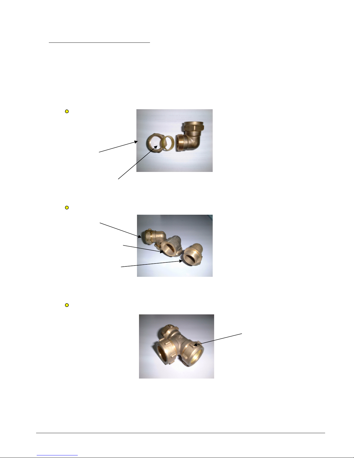
Copper Pipe: Compression Fittings
For some installations, the piping are connected using compression fittings. These fittings
enable easy installation and dismantling. However, the cost for these fittings are higher.
They are also not as strong as brazing joints. Chances of leakage are higher.
Generally, the fittings have mounting rings which are slipped onto the copper pipes. The
ring is then pushed against the fitting internal surface and a locking nut is used to hold the
assembly together.
90° elbow
L
ocking nut
mounting ring
90
° elbow with threaded ends
normal elbow
female thread
with steel pipe fittings,
male thread
Such elbows are for special
applications. For example,
connection with steel pipe
fittings, connection with a
water tank.
tee joint
ribs for gripping with
a wrench
Section: 3 Page 36
Page 39

connector
female thread
Used for connecting two pipes together.
Some have threaded ends for connection with other fittings.
union
locking nut The two halves opened up
threaded end
Similar to the steel type. Used for connecting two pipe together with flexibility of easy connection
and dismantling.
Some have threaded ends, others with compression fitting ends.
In some installations, the copper pipes are brazed (with silver flux) onto each half of the union and
then connected together with the locking nut.
NOTE: Brazing of copper to brass requires filler rods with 34% silver.
Section: 3 Page 37
Page 40

c) PVC Pipe
It is recommended that the PVC pipe fittings used to be in accordance to the DIN 8062
standards. These fittings have thicker walls and able to withstand higher pressures and
temperatures.
Generally, these fittings are the cheapest and easiest to install.
90° elbow
With the threaded end,
some elbows it is also possible to
have threaded connect with a steel pipe
ends or steel fitting.
tee joints
connector
Used to connect two PVC
Pipes together with solvent
cement
Section: 3 Page 38
Page 41

adaptor/sockets
The sockets may have
male or female threaded
ends.
Such sockets are useful
to adapt connection with
a steel pipe or tank.
union
locking nut the two halves of the
union
Similar to the steel and copper versions, these unions enable easy connection and dismantling of
two PVC pipe ends.
The PVC pipes are joined to the two halves by using solvent cement and then they are
assembled together with the locking nut.
reducer
Section: 3 Page 39
Page 42
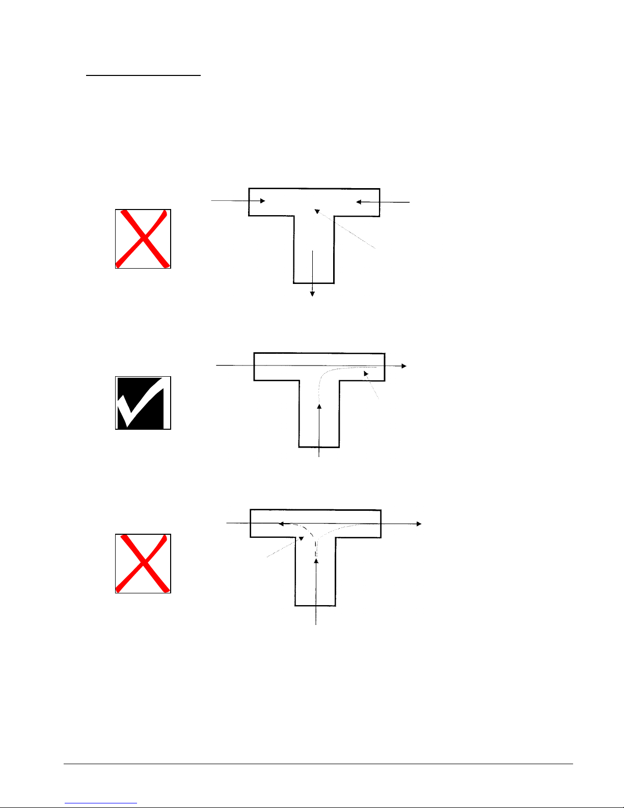
Tee Joint Installation
Care must be taken during installation of tee joints. Two cases are mentioned here
to demonstrate the importance of understanding the design of the water flow system.
a. Avoid "bullheading"
Do not connect piping to the tee connection with opposing flow directions.
turbulence occurs here and
causes high friction losses
b
. Encourage eduction out of a bypass tee branch.
return
wate
r
the higher velocity of flow in
the run of the ‘pulls’ water
our of the tee branch
bypass
branch
bypass
branch
Do not allow the higher return
water velocity to ‘ram’ into the tee
joint. This may cause a backflow
into the bypass branch.
backflow of
water
return water
Section: 3 Page 40
Page 43

Valves
In Section 2, we have look at several piping network configurations. The diagrams shown in that
section have been simplified. In actual situation, the piping will have most of the pipe fittings
described earlier in this Section 3. In addition, valves are also installed along the piping lines.
Valves are used for the following purposes:
a. To isolate a component of the hydronic system from the rest of the system; thereby enabling
easy maintenance and repair of that component.
b. To regulate the water flow rate through the system.
c. To divert or mix flow directions, optimizing the water temperature in the system.
d. To relieve or regulate pressure.
e. To prevent backflow.
Valves are constructed to withstand a specific range of temperature, pressure, corrosion and
mechanical stress. Careful selection of the correct valve for a particular application is
important to give the best service with consideration of economic requirements.
The following diagram gives the general anatomy of a valve:
Section 3 Page 41
Page 44

Generally, valves can be categorised as manual or automatic valves.
Manual Valves
The following are the types of manual valves commonly used in hydronic systems:
1. Globe Valve
Flow is controlled by a circular disc forced against or withdrawn from an annular
ring, or seat, that surrounds an opening through which flow occurs.
The movement of the disc is parallel to the flow direction.
- used for pipe diameters up to 300mm
- used for throttling duty where positive shutoff is required
2. Gate Valve
Flow is controlled by means of a wedge disc fitting against seating faces.
Gate movement is pependicular to the flow direction.
- has straight-through openings as large as the full bore of the pipe.
- this type of valves are intended to be fully open or fully closed
- should not be used to regulate or control flow
- useful for isolation/shut-off purposes.
Section 3 Page 42
Page 45

3. Ball Valve
This valve has a precision ball seated between two circular seals or seats.
A 90° turn of the handle will change the operation from fully open to fully closed.
- may be used for throttling duty
- generally used with smaller pipe diameters (up to 75mm)
4. Butterfly Valve
This valve has a cylindrical body with an internal rotatable disc serving as the fluid flow
regulating device. This disc's axis of rotation is the valve stem and it is pependicular to
the flow direction. A 90° turn will change the operation from fully open to fully closed.
- has low pressure drops
- fast operation of valve
- may be used for throttling duty
Section 3 Page 43
Page 46

5. Balancing Valve
This type of valve provide throttling duty to regulate water flow rate for balancing purposes.
Two ports are provided in the inlet and outlet ports of the valve to permit measurement of
pressure drop across the valve. By using performance charts provided, the value of flow
rate through the valve can be determined. The valve handwheel will have a setting scale to
determine the amount of valve opening. This is useful during field commissioning and
balancing.
Generally, the internal construction is similar to a globe valve. It is more costly
than the conventional throttling valves and it is only used in systems where
proper and accurate balancing is required.
Normally, connected via
tubing to a hand-held
meter readout
pressure tapping
Setting handwhell
Section 3 Page 44
Page 47

Automatic Valves
This type of valves operate in conjunction with an automatic controller or device to control
the fluid flow. These controllers are also called as actuators. There are several types of
actuators commonly used:
a. Solenoid
b. Electric motor
c. Pneumatic
Such actuators will have gears, rack-and-pinion, cams and linkages to convert movement
and allow opening and closing of the valve stem.
a. Solenoid Valve
This type of valve only allows either a totally open or close position. It has a
magnetic coil which will lifts or drops a plunger in the valve to open and close the
flow of water. This occurs when the coil is either energized or de-energized.
Such valves are generally used for pipe sizes up to 50mm only. They are suitable
for small fan coil units which require water shut-off when the fan coil is switched
off.
solenoid coil
b. Electric Motorised Valve
The actuator has a built-in motor to produce a rotary motion. By using gears,
cams or linkages, the valve stem will be opened or closed. Usually, the motor runs
on DC power supply (24V).
Generally, the actuator has positioning controls whereby the valve can stroke to
any position between fully close to fully open. This is accomplished with a control
signal from an external feedback controller.
With this feature, it is possible to vary the water flow rate to suit any demand load
of an application.
Nevertheless, the cost of such valves is high.
Section 3 Page 45
Page 48

motor drive
valve (encased in
insulation)
position indicator
c. Pneumatic Valve
This type of valve has a flexible diaphragm clamped between an upper and lower
housing. The valve stem is attached to the diaphragm. By injecting air pressure
into the upper housing, the diaphragm will push the valve stem. An opposing
spring force on the valve stem will also resist this movement. Therefore, by varying
this air pressure, valve positioning can be achieved.
For this to work, an external pneumatic converter/positioner must be used to
regulate the air pressure. A thermostat may be used together for such a purpose.
This cost for this type of valves is also high.
upper housing
diaphragm
lower housing
spring
valve body
air pressure inlet
Section 3 Page 46
Page 49

Two Way and Three Way Valves
Automatic control valves used in hydronic systems may be classified as either two-way
or three-way. All three types of actuators mentioned above may be used for these two
types of valves.
In the two-way valve, water flows into the inlet port and exits from the outlet port. By means
of the actuator, the flow rate may vary from full flow to zero.
There are two types available: single-seated
and double-seated. For most applications,
the single-seated type will suffice. In this type, there is only one valve seat and one plug-disc
to clsoe against the flow. However, for applications with higher operating pressures, the
double-seated types may be used.
attachment to actuator
Water In
Water Out
In the three-way valve, three ports are available. Depending on the application, these
can be configured as a mixing
or diverting valve.
1. Mixing Valve attachment to
- two streams of water blends into a single stream
actuator
A A+B
B
1
2. Diverting Valve
-splits one stream into two different streams
2
A+B B
3
A
Section 3 Page 47
Page 50

Capacity Control With 2-Way and 3-Way Valves
supply return supply ret
urn
The load of the fan coil unit can be calculated from the equation:
Q = 4180 * (water flow rate, L/s) * (water temperature differential.°C) Watt
th the 2- ay and 3- ay
alve will vary t
∆t".
LOAD LOAD
LOAD
diverting
mixing
Therefore, the load is propotional to the water flow rate and ∆t. Bo w w
v he flow rate to accomodate changes in the load demand.
With the 2-way valve, the system is considered as "variable flow, constant ∆t".
With the 3-way valve, the system is considered as "constant flow, variable
It is recommended that the 3-way valve to be configured as a diverting valve
instead of a mixing
valve. This is because when the fan coil unit is OFF, cold water will not enter into the heat
exchanger with the valve diverting the water away to the return line. Unlike the mixing valve, even
though the valve may be closed, cold water can still enter into the heat exchanger and ccumulate
there. As a result, sweating
on the heat exchanger and the connecting joints will occur even
the fan coil unit is not running.
However, on the o
when
ch valves, choosing instead the mixing configuration.
ther hand, 3-way diverting valves cost more than mixing valves. This is why
some designs do not call for su
Section 3 Page 48
Page 51

Application:
Both the two-way and three-way valves are suitable for shut-off and flow regulation purposes.
The cost of the two-way valves are cheaper compared with the three-way valves. Thus,
there is a tendency to use the two-way valves during installations.
A typical two-way valve installation:
The problem with the above installation occurs when both the fan coil units are switched off.
he controls of the fan coil unit will also at the same time switch off the solenoid valves, i.e.
FAN COIL UNIT 1
FAN COIL UNIT 2
Mini Chiller
2-way solenoid
2-way solenoid
T
there will not be any water flow through the system when the fan coils are not in use.
However, the chiller pump is still running. Therefore, the water pressure built-up in the piping
may cause damage to the water pump or to the valves themselves (valve stem lifting).
Usage of 2-way valves will require additional design considerations:
a. Add a Bypass Line to Relief Pressure
LOAD
∆
P
LOAD
LOAD
Different pressure transmitter to monitor the amount of water used. If
pressure goes higher than preset value, it will open the relief
bypass the water
valve and
Section 3 Page 49
Page 52

b. Use a Variable Speed Drive for the Secondary Water Pump.
LOAD
LOAD
LOAD
∆
P
INV
primary loop
When the differential pressure becomes higher, the inverter will slows
down the water pump to maintain the head pressure. If no demand,
the water pump will stop running.
c. Modify the Control Wiring for Chiller and Fan Coil Unit.
The above two methods will incur high cost due to the extra piping, pressure transmitter and
other necessary fittings/equipment.
An easier method is to change the control wiring of the system. Conventionally, when the
fan coil unit thermostat cuts-off, the power supply to the control 2-way valve will be off.
It is possible to run a line from the thermostat to the chiller remote switch whereby
when the thermostat cuts-off, the chiller unit (and the pump) will also switch off.
See Section 11 on 'Electrical Wiring Control' for more details.
However, the disadvantage with this method is that the chiller cycle on-off more frequently
and the water supply temperature will fluctuate up and down.
d. In view of the difficulties mentioned above, it is recommended that 3-way
diverting valves to be used in the mini chiller hydronic system.
Since the 3-way valve gives a constant flow system, there will not be any problem when
there is no load demand since the water will bypass through the valve when it is in the
fully closed position (with respect to the load).
Section 3 Page 50
Page 53

LOAD
LOAD
LOAD
However, this system has one main disadvantage. Since the supply water is by-passed around
the load coil, energy is wasted
. This will cause the chiller to cycle on-off more frequent as the
return water temperature becomes lower.
Therefore, in terms of energy efficiency, applications with 2-way valves are better.
Section 3 Page 51
Page 54

Other Type of Valves and Fittings
a. Check Valve
This valve will only allow flow in one direction, i.e. to prevent back flow of water.
We have seen an example of usage in Section 2 with multiple chillers installation.
There are two basic design of these check valves:
1. swing check valve - can be installed in horizontal or vertical piping
2. lift check valve - only for horizontal piping installation
Swing check valve
Lift check valve
b. Plug Cock/Plug Valve
This type of valve is also used for throttling duty. It is less expansive compared with the
globe valve or balancing valve. The setting also cannot be tampered with as easily as the
globe valve.
Valve stem without handwheel. Use
a spanner or wrench to open and close
valve.
Plug with orifice port. With a 90° turn, the
port will operate from fully open to fully
close.
Section 3 Page 52
Page 55

c. Pressure Gauge Cock
Generally, this valve is a ball valve. It is used to isolate pressure gauges installed along
the water pipe lines.
Main pipe line
Pressure gauge
Impulse tubing loop
Gauge cock (Ball valve)
The gauge cock is only opened during pressure measurement. When not in use, the valve
is closed to prevent prolonged pressurising to the gauge, therefore preventing damage
to the gauge itself. It is also closed when changing a new gauge.
d. Safety Relief Valve [Optional]
The valve will open when the pressure exceeds a set value to prevent over pressuring the
system which may cause damage. Normally, this is used when the system is running
hot water (mini chiller in heating mode/reverse cycle) in a closed piping. The hotter the water
temperature, the higher is the pressure due to expansion.
Such valves are also useful for protection against sudden pressure shocks, e.g. water
hammering, and overpressuring from water fill system.
If the system is with an open piping and external tank, this valve may be exempted.
The setting of the valve should be at least 10% higher than the expected maximum operating
pressure. It should be installed at the location where this pressure may be expected to
occur, e.g. near any expansion tanks or pump discharge lines.
Pipe the exhaust from the relief valve to an external drain.
Section 3 Page 53
Page 56

e. Air Vent Valve
The mini chiller unit has an automatic air vent located on top of the buffer tank. This is to
release any trapped air inside the tank which may cause problem to the pumping operation.
This is especially so during heating operation where oxygen and hydrogen gases are formed
from the water and gets accumulated inside the tank. Air entrainment and microleaks along
the joints and valves of the pump suction line will also cause air to enter the water system.
Therefore, it is a good practice to install another air vent at the highest position
of the piping
network to ensure that the pump performance do not deteriorates.
Such air vents are also useful during commissioning and system start-ups to release any
air trapped in the piping system.
Always install the valve in a vertical position on top of a tank or pipe.
pipe
air vent
air vent
CORRECT INCORRECT
Under normal condition, water will enter inside the valve and lifts a floating body
which will raise a mechanism to close a pin-shutter. Reduction of the water level
as a result of accumulated air will cause the float to drop and opens the pin-shutter
thus releasing the air automatically.
float body
pin-shutter opens
Air venting Normal
Section 3 Page 54
Page 57

f. Strainer
The strainer is an important element in the piping system to remove particles (e.g. sand)
and dirt from the water. If not, these impurities will damage the pumping mechanism and
clogged-up valves and fittings.
IMPORTANT!!!
The mini chiller unit do not have a strainer built-in. Always install a strainer on
the water inlet pipe into the chiller to protect the internal water pump.
straine
r
CHILLER
water outlet
water inlet
Do not install strainer on the water outlet pipe as the water velocity is higher.
Install the strainer with the filter element in a downward position. This is to facilitate easy
flushing during periodic cleaning.
allow sufficient s
p
ace to remove filte
r
strainer with filter in downward
p
osition
pump
floor
## This method is not recommended
pump
straine
r
Section 3 Page 55
Page 58

water inlet
filter mesh 16 – 20
recommended
There is also a practice to install a strainer on the inlet pipe to a fan coil unit. This is
done to protect the control valve, located at the outlet pipe, from clogging.
strainer
FAN COIL UNIT
2-way valve
to measure th water te peratur
stallation can be done with a socket welded onto the pipe or a tee joint connection.
g. Thermometer
Glass thermometers are installed on the inlet and outlet pipes of either the chiller unit
or fan coil units. This is e m e differential to determine the
capacity performance.
Usually, these thermometers are installed together with the pressure gauges.
In
r
threadedjoint
welded
j
oint
threaded
thermomete
socket
Flow
j
oint
tee
j
oint
Thermometers can be installed vertically, horizontally or even at an angle.
Section 3 Page 56
Page 59

During installation, it is important to ensure that the sensing bulb is in touch with the flowing
stream of water. If the thermometer is installed too "high" up the connecting socket, the
bulb will measure the temperature of stagnant water in the socket.
thermometer too
high up
stagnant water
Thermometer bulb
measuring correct
water flow
temperature
CORRECT INCORRECT
Section 3 Page 57
Page 60

Valve Sizing
In selecting the suitable valve to use for an application, the following items must be
considered:
1. What is the fluid medium of usage.
In chillers, the fluid is water. There are valves specially designed other fluids e.g. steam and
air, which are not suitable for water.
2. What is maximum operating pressure and temperature.
3. What is the valve duty required - is it for throttling, shut-off, balancing, mixing, etc.
4. What is the pipe size to be connected
Do not oversize or undersize a valve to suit the pipe size. Size the valve according to the
flow requirements. Use reducers where applicable.
5. What is the flow rate required through the valve
6. What is the flow characteristics required - linear, equal percentage (See following pages)
7. What is the piping connection method to the valve - threaded, flanged
Most of the above mentioned information may be obtained from the valve catalogs provided
by the valve manufacturers.
In sizing the valve, the general accepted method is by means of the C
v
(flow coefficient).
Different valves will have different C
v
values.
Formula:
Q = Cv * (∆p)
Definition: The C
v
rating of any valve is the amount of water,Q (GPM) at standard conditions
(60°F, specific graviti = 1) which will pass through the valve with a pressure drop, ∆p of 1 psi
with the valve in a full open position.
By using conversion factors, we can have the flow coefficient K
v
in metric units:
1 C
v
= 0.857 Kv
Definition: The K
v
rating of any valve is the amount of water (m3/hr) at standard conditions
(20°C, specific graviti = 1) which will pass through the valve with a pressure drop of 1 kg/cm
2
with the valve in a full open position.
If the reference pressure is 1 bar, then:
1 C
v
= 0.867 Kv
Section 3 Page 58
Page 61

For a given flow rate, we can select a valve with suitable Cv to give an appropriate pressure
drop. These data are available in graphs provided by the manufacturer. See Appendix 5.
Selection of the valve must be done so as not to have too high a pressure drop, else the
water pump head will be insufficient for the system. The values of these valve pressure
drop can also be used during pump sizing. See Section 5.
For control valves (modulating, throttling duty, 2-way and 3-way), the pressure drop should
be no less than half the total pressure drop in the branch. This will allow a stable control.
Example :
Pressure drop = 6 feet
FAN COIL UNIT
A
B
3-wa
y
supply
return
Pressure losses along piping works from A to B = 4.6 feet
Pressure drop across 2 gate valves + coil heat exchanger = 6 feet
Therefore, the control 3-way valve should have a pressure drop of at least
= 2 * (4.6 + 6)
= 21.2 feet
= 9.2 psi ** Conversion: 1 psi = 2.309 feet water
If the flow rate through the branch is 6 GPM, what valve C
v
should be used?
Refering to the graph in Appendix 5, the C
v
should be 2.
Therefore, a 3-way diverting valve with C
v
of 2 (at full opening) should be selected
for the above application.
As can be seen from the example above, the valve sizing was done with the design flow
at full opening. Thus, at reduced flows, the valve will close and this will increase the
pressure drop.
This can be seen from the following graph which depicts the system curve and pump
curve for a single fan coil load. See Section 5 for more details on pump curves.
Section 3 Page 59
Page 62

Head Pressure
pressure drop
of control valve
at full opening
increased
pressure
drop with
reduced
flow
pressure
drop of
val ve wi th
zero flow
pump curve
system curve w/o control valve
Flow rate
Reduced flow Design flow
Another consideration in selecting the suitable valve is to determine the flow characteristic
through the valve. Generally, there are three types:
1. Quick Opening
The valve shows a quick increase of flow for a small increase of opening. But as it reaches
the open position, the rate at which the flow increases per movement of the opening reduces.
2. Linear
This valve produces equal rate of flow increase per equal rate of opening.
3. Equal Percentage
This type of valve produces an exponential flow increase as the valve opens up. The term
equal percentage means that for equal amouts of valve opening, the flow increases by the
same percentage.
SELECT THIS TYPE OF
CHARACTERISTICS
Section 3 Page 60
Page 63

Selection of valve with equal percentage flow characteristics will give the best performance
as this will give a linear heat transfer rate with flow rate:
Heat transfer
rate, %
Valve opening Flow rate, %
For automatic on-off valves (e.g. solenoid 2-way, 3-way), the selection is easier. Generally,
use the same size as the pipe size, with a low pressure drop (e.g; 2 -5 psig: fully open).
Using a smaller size (with pipe reducers and adaptors), for economic reasons, is possible,
but check for excessive pressure losses which will reduce the pump performance.
Section 3 Page 61
Page 64

Guidelines for Valve and Fitting Installation:
a. Gate valves (shut-off) are installed in the entering and leaving piping to the chiller and
fan coil unit. This is to permit servicing and replacement of the equipment without draining
the system. A globe valve may be used to serve as one of the shut-off valve and in
addition to balance the flow rate.
b. Valves and fittings using threaded or welded joints will require unions to permit easy
removal for servicing or replacement. Unions are usually located between each gate valve
and the equipment. Unions are also place before and after the control valve, and in the
branch of the 3-way valve.
If flange joints are used, the need for unions is eliminated.
c. Locate the control valve in between the gate valve and the equipment to permit removal
of the control valve without draining the system.
d. Strainers, thermometers and pressure gauges are located between the gate valve and
the equipment.
Section 3 Page 62
Page 65

The following diagrams illustrate examples of piping layout:
P
T
P
T
Typical Mini Chiller Piping Installation:
Water su
pply
Water return
1-1/4” connecto
r
Make-up water (from
main supply or water
tank)
RETURN
SUPPLY
gauge cock
FAN COIL UNIT
Typical Fan Coil Unit Installation:
a. Horizontal installation
Section 3 Page 63
Page 66

Section 3 Page 64
Supply riser T
Return riser
T
FAN COIL UNIT
3-way mixing valve
tee joint
air vent
globe valve
FAN COIL 1 FAN COIL 2 FAN COIL 3
T
T
3-way
diverting
valve
b. Vertical Installation
T
T
o Multiple Fan Coil Unit Installation
T
** All three fan coil units to serve one area with a
common thermostat. When temperature has
reached set point, thermostat will send signal to 3 way valve to divert water away.
Page 67

Section 3 Page 65
CHILLER 3
CHILLER 2
CHILLER 1
T
P
T
P
check valve glove valve
Make-up
water
Return
Supply
Multiple Chiller Installation
Common Header
** Globe valve will be used to balance the flow rate through each chiller unit.
** Additional gate valves may be installed along the main supply and return lines
to isolate the entire chiller assembly.
Page 68

Primary-Secondary System
glove valve
secondary pump
RETURN
CHILLER
tee joint
(Remember ! Do not encourage
bullheading here)
Water Tank Installation (Open System)
RETURN
RETURN
TANK
adaptor(c/w nubber gasket)
To external pump
CHILLER
SUPPLY
Section 3 Page 66
Page 69

Section 4: Pipe and Fitting Sizing
In the previous section, we have looked at the different types of pipes which can be used in a
hydronic system. We have also looked at the various types of fittings used in conjunction with
the piping.
In this section, we will examine the friction losses
which occur when water flows through the pipes
and fittings.
Friction losses are dependent on the following factors:
a. Water velocity
b. Pipe internal diameter
c. Pipe length
d. Pipe internal wall roughness
Generally, friction increases when:
- Water velocity increases
- Internal diameter decreases
- Pipe length increases
- Wall roughness increases
The basic formula to calculate pipe friction losses (Hf) is the Darcy-Weisbach formula:
Hf = f * (L/D) * v
2
/2g where f = friction factor
L = pipe length
D = pipe internal diameter
v = mean velocity
g = acceleration due to gravity
The friction factor is a function of the roughness parameter, e, which in turn
depends on the pipe material (e.g. steel, copper, PVC), and the Reynolds number,
Re.
Re = D * v ρ / * µ where ρ = density
µ = dynamic viscosity
Generally, the friction losses are presented in graphical form, for various pipe material.
See attached charts for steel pipe Schedule 40,copper pipe and PVC.
Note that Carrier
has developed two different type of graphs for steel pipes, i.e. for close and
open system. The friction losses for the open system is higher than the close system, for the
same parameters. This is to take into account the vulnerability of open systems to cause pipe
fouling and scaling on the internal surfaces. A factor of approximately 1.75 is used for this
purpose.
It is to be noted that the pipe friction loss charts presented are all for flows in the turbulent regime
(Re > 10 000).
Section 4 Page 67
Page 70

Water Flow Limitations
The factors which determine the water velocity limits are noise, erosion and installation cost. If the
piping is too small, noise and erosion levels will become unfavourable even though the cost is
more economical. Conversely, choosing a larger pipe will incur higher costs.
It is recommended that the following guidelines to be used for the mini chiller units:
1. The pipe friction loss used for the design of the system should be between 1 to 4 ft per 100
ft of equivalent pipe length.
2. The velocity in the pipe should be less than 4 fps in view of the allowable noise level
generated for residential and commercial buildings.
However, the noise is not caused by the water itself, but rather by free air, sharp pressure
drops, turbulence, cavitation and flashing. If precautions are taken to eliminate air and
turbulences, higher velocities up to 8 fps are acceptable.
3. The minimum velocity in the pipe should be 1.5 - 2 fps to allow air entrained in the water to be
carried to separation units (e.g. expansion tanks, locations of lowest pressure) for venting.
Taking into consideration (2) and (3) above, it is recommended that the water velocity in the
pipe to be 2 - 8 fps. With this, the expected service life of the pipes is more than 8000
hours/year.
Conversion factors:
1 fps = 0.305 m/s
1 ft water = 248.84 Pa
1 ft = 0.305 m
Example:
All the mini chiller units are with 1-1/4" pipe connections. Installation with 1-1/4" and 1" piping is
possible, as shown in the following calculation for steel Sch 40:
Pipe size 1-1/4" Pipe size 1"
Internal diameter = 1.3799" Internal diameter = 1.0488"
Cross sectional area = 0.0104 ft
2
Cross sectional area = 0.006 ft2
Section 4 Page 68
Page 71

The following data are extracted from the mini chiller technical manual:
Water flowrate Velocity, fps
Model
USGPM ft
3
/min 1-1/4" 1"
AC 40A
6.7 0.89 1.43 2.47
AC 50A
8.9 1.19 1.91 3.30
AC 58A
11.1 1.48 2.38 4.12
AC 75B
17.8 2.37 3.80 6.59
AC100B
22.2 2.97 4.75
8.24
AC125B
27.7 3.71 5.94
10.30
AC80C
17.5 2.34 3.75 6.50
AC100C
20.8 2.78 4.46 7.72
AC120C
26.7 3.57 5.72
9.92
AC150C
31.7 4.24 6.79
11.78
It is not recommended
to install these units
with 1” pipe size.
Section 4 Page 69
Page 72

Equivalent Pipe Length
The concept of equivalent pipe length is very useful in calculating friction losses along the
hydronic pipe system.
Defination:
The equivalent pipe length of a component in the pipe system is the length of a
straight pipe which will give the same friction losses as the component itself.
For example, we have a 1" elbow which gives a pressure drop of ∆P when a
flowrate of Q passes through it. If a straight 1" pipe of length y feet gives the same
pressure drop when a flowrate of Q flows through it, then, the equivalent pipe length
of that elbow is y feet.
It is just like thinking that the elbow has been "replaced" with the length of straight
pipe.
Naturally, a straight pipe in the hydronic system do not require such usage of equivalent length.
Therefore, the total equivalent pipe length of a hydronic system
= straight pipe length + equivalent pipe length of all fittings and valves along the
pipe
Generally, equivalent pipe lengths of common valves and fittings are available. See attached
tables (Appendix 7).
An alternative method was published in the "ASHRAE Handbook: Fundamentals" for calculating
the equivalent pipe length of tee joints. A graph is used to determine the number of equivalent
elbows for the various flow conditions through the tee. This is then multiplied with the equivalent
pipe length/pressure loss for the same size elbow. See Appendix 7.
It must be noted that the equivalent lengths given in the attached tables for the fittings are
only estimates. The values are more meaningful when used for steel pipes.
Friction losses of copper and PVC fittings (e.g. elbows, tees, reducers) are quite similar to the
equivalent steel type. Therefore, for estimation purposes, it is sufficient that the same equivalent
lengths to be used for both copper and PVC pipes.
Nevertheless, friction loss values
for different pipe material will be used in the computation of the
total friction in the piping system.
If specific friction losses for any fitting is available from the manufacturer, it is advisable to use
these values instead of the estimates given in the tables. This is especially applicable to valves
(specific C
v
) and strainers (different mesh sizes).
Section 4 Page 70
Page 73

Internal and External Friction Losses
The friction losses of the straight pipes and fittings are considered external losses to the hydronic
system. Other than that, there are also losses in the chiller unit itself, i.e. through the brazed plate
heat exchanger (BPHE), internal pipework, pump fittings, flow switch, etc.
All these internal losses
are as tabulated below:
Friction loss, Nominal water
Model
psi flow rate, GPM
AC 40A/AR
5.4 6.7
AC 50A/AR
6.4 8.9
AC 58A/AR
5.7 11.1
AC 75B/BR
6.0 17.8
AC 100B/BR
6.5 22.2
AC 125B/BR
6.6 27.7
AC 80C/CR
5.9 17.5
AC 100C/CR
12.5 20.8
AC 120C/CR
6.4 26.7
AC 150C/CR
9.9 31.7
In the same manner, each fan coil unit has its own internal losses through the heat exchanger.
Please refer to the respective Technical Manual for the values of these losses.
Section 4 Page 71
Page 74

Friction Loss Calculation
It is of utmost importance that a calculation to be made to determine the total friction loss along
the piping network. This is to ensure that the water pump is able to deliver the required flow rate
through the system. If the friction loss is too high, the flow rate will reduce, thereby causing
improper operation of the chiller. If the friction loss is too low, the piping system may be
redesigned for cost savings and better efficiency.
The following guidelines should be followed during calculation:
1. It is necessary to have a drawing of the entire piping network, showing the lengths,
sizes, material and fittings used. Such drawing may be in 2-dimensional or 3 dimensional (preferred).
If the system is an open type, determine the height difference between the chiller
unit and storage tank (if any).
The straight length of a pipe is measured from center-to-center of each fitting
along the pipe.
2. It is a good practice to have markings on the drawing for each branch of the pipe
network. This will help in identification of which branch is being calculated.
3. The following information must be available for calculation: water flow rate (GPM) of
each pipe branch, internal friction losses of the chiller unit / fan coil unit and water
pump head available.
These information can be obtained from the product catalogs or technical manuals.
4. Calculate for the branch which gives the highest friction loss. This usually
corresponds to the branch which have the furthest fan coil unit from the chiller.
5. It would be better to have the actual pressure drop across any of the fittings used
vs. the estimated equivalent lengths presented in the attached tables. This is
especially so for the valves (with specific C
v
values) and strainers (with different
mesh sizes).
6. Add a safety factor of 15 - 20% to the final friction loss to account for estimation
errors and actual site installation of the piping system.
7. Check the final friction loss against the pump head available. The pump head
must be higher than this calculated value if the system is to work properly.
An EXCEL spreadsheet programme has been written to help in this friction loss calculation.
Several worked examples are shown for typical installations in the following pages. The EXCEL
programme has been used in the computation.
Section 4 Page 72
Page 75

Section 5: Water Pump
We have seen in Introduction that the pump is one of the fundamental component in a hydronic
system. It circulates the water through all the other components in the system.
We have also seen that in the mini-chiller unit, this pump is incorporated together with the other
components as one package.
In order to operate the chiller properly, it is vital to have an understanding of the pump
characteristics and the factors which affect its performance.
The water pump used in the mini-chiller unit is of the end-suction centrifugal type. Water enters
through an inlet port at the center of an impeller and is pushed out by centrifugal forces of the
impeller to a discharge volute around the impeller. As a result, a water pressure head is
developed at the discharge port.
To rotate the impeller, the pump assembly is coupled with an induction motor. Therefore, torque
developed by the electric motor serves as the input power to the pump and gets converted as
output in the form of the water head pressure.
Factors which describes the performance of a pump:
a) Volumetric Flowrate
b) Head Pressure
c) Input Power
d) Efficiency
e) NPSH (nett positive suction head)
Various pump designs are available to meet different requirements. Some of the common
parameters which pump manufacturers use for their design are:
1. Impeller Diameter
Generally, the larger impeller will give higher flowrate and higher head pressure.
2. Number of Impellers
These multiple stages
will increase the flowrate and head pressure as compared to a
single stage impeller.
3. Impeller Speed
Most pumps are of the single speed design. However, variable speed pumps are also
available which requires the usage of a speed controller (e.g.inverter unit). Generally, the faster
the impeller rotational speed, the higher the flowrate and head pressure.
4. Material of Impeller and Pump Body
This will depend on the usage of the pump. Stainless steel and cast iron are two common
materials used for the impeller and body. Applications which requires clean and hygienic
pumping medium will require usage of stainless steel, e.g. for domestic water supply and food
industries. Cast iron are sufficient for sewerage systems.
5. Pump Configuration/Type
There are various other types of pumps to suit the pumping needs, e.g. in-line centrifugal
pumps, submersible pumps, dosing pumps, etc.
Section 5 Page 73
Page 76

Proper selection of the pump is crucial to meet the pumping requirements. Other factors like the
operating temperature and pressure of the medium must also be considered in the selection.
Refer to the corresponding pump specifications and catalogs for detailed information of the
pumps.
The multistage end-suction pump used in the mini-chillers are from GRUNDFOS.
The models involved are:
Mini-Chiller
Model
AC 40A/AR CH2-30
AC 50A/AR CH2-30
AC 58A/AR CH2-30
AC 75B/BR CH4-40
AC 100B/BR CH4-40
AC 125B/BR CH4-40
AC 80C/CR CH4-40
AC 100C/CR CH4-40
AC 120C/CR CH8-40
AC 150C/CR CH8-40
The impeller and all movable parts in contact with the water are made of stainless steel.
The pump suction and discharge chambers are made of cast iron.
Please refer to the attached Technical Product Information for more detailed information.
(Appendix 8)
Section 5 Page 74
Page 77
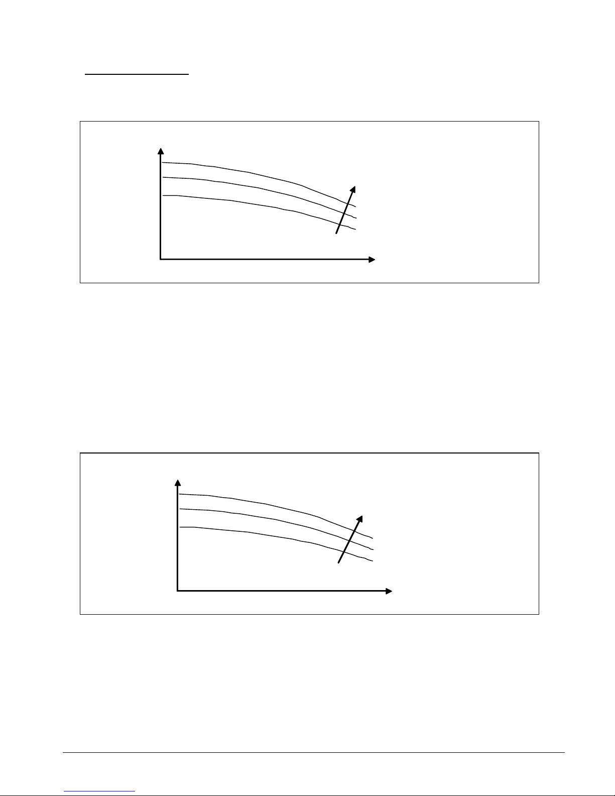
Pump Performance
One of the most useful performance chart of a pump is the P-Q curve, which describes
the relationship between the head pressure (P) vs. the volumetric flowrate (Q). The shape
of the curve is as follows:
P
With increasing impeller
diameter
Q
This curve shows that when the head pressure increases, the flow rate reduces (and viceversa). By calculating the system pressure drop, we can thus determine the flow rate when
the pump is running. Hence, we can check whether the system pipe design is suitable for
a particular pump application.
This pump head pressure can also be measured at the pump discharge port by using a
pressure gauge.
The above curve is for a single fixed speed pump. If the pump were to operate under
different power supply frequencies (e.g. from 50 Hz to 60 Hz), another set of curves must
be used.
For variable speed pumps, the P-Q curves will look as follows:
P
With increasing
RPM speed of
impeller
Q
Section 5 Page 75
Page 78

Let us now examine the sample calculation of the friction loss shown in Application Example
No. 1 (Section 4).
The flowrate in that example is 11 USGPM = 2.497 m
3
/hr at a total friction loss of 14.67m.
For the mini chiller model AC 58A, the pump used is CH2-30.
2.497 m3 /hr
The performance curve of the pump
shows that at the design flowrate, the
pump is able to deliver a head
pressure of 20 m. This is more
than sufficient to cater for the
total system friction loss.
Therefore, the pump is OK.
20 m
Similarly, in Application Example No. 2, we have a flowrate of 27 usgpm with a requirement
of total friction loss of 26.4m. Entering now into the pump performance curve of CH4-40,
we find that at this flowrate, the pump can only deliver a head pressure of 19 m.
27 USGPM
his is not enough for the system.
ate.
T
Therefore, it is necessary to
redesign the piping network
to have a lower friction loss
in order for the pump to
deliver the required flowr
19 m
Section 5 Page 76
Page 79

System Curve
The system curve of a hydronic system is a plot of the pressure loss vs. the flowrate of the piping
system itself. This curve describes the performance of the piping network itself. By plotting this
curve onto the pump P-Q curve, we have the following:
P
pump curve
operating point
system curve
Q
Note that the characteristics of the system curve is the opposite of the pump curve, whereby
water will have a higher pressure loss in the piping system when the flowrate is higher.
The intersection of these two lines will give the operating point
of the system.
What we have done in the Application Example No. 1 and 2 is to calculate the desired design
operating point of the mini chiller with that particular piping network. In the first example, we have
found that the pump has a much higher capacity compared with the requirement (System Curve
1)
P
system curve 2
20 system curve 1
dP
pump curve
2.5 Q
calculated operating point
which does not lie on the pump curve
In order to "balance" back the pump operation, we need to increase the piping friction loss
by dP (e.g. by adjusting the globe valve) so as to obtain System Curve 2. If this is not done,
the pump will deliver a much higher flowrate compared with the design value.
Section 5 Page 77
Page 80

In the second example, we find that the water pump is insufficient to cater for the system curve.
P
system curve 1
26
dP
calculated operating point which
lies above the pump curve
19
pump curve
system curve 2
In order to use the mini chiller, it is necessary for the piping network to have a characteristic of
System Curve 2. The only way to do so is to redesign the piping system to give a lower friction
loss.
Alternatively, we can use the pump P-Q curve during commissioning of the hydronic system. To
do so, we need to measure the water pressure at the discharge port. This value is quite close to
the actual head pressure developed by the pump. By plotting this pressure on the P-Q curve, we
can then determine the approximate flowrate flowing through the system and compare it with the
design requirement. Appropriate action can then be taken to ensure sufficient and correct amount
of flowrate.
P1
Water pressure measurement
To load with a design
flowrate, q, and total
pressure loss, p
MINI CHILLER
P
Design point
Actual opening point
Measurement
P1
Q
q
Section 5 Page 78
Page 81

Parallel and Series Pump Operation
We have seen examples of the mini-chillers operating in parallel, e.g. where they are connected
together via a common supply and return header pipe. Such installations are common when the
single chiller do not have sufficient cooling capacity. In the parallel operation, the water pumps
will work together to deliver a higher water flowrate (which is equivalent to the summation
of each
individual pump flowrate) at the operating head pressure.
Example
: Two mini-chillers of the same model are connected together to a load as shown
schematically (simplified) below:
header
C1
Load
C2
The pump in each chiller is delivering a flow of ϖ GPM. Assume that the friction loss
in each branch of the header pipe is the same. Therefore, the flow in the load will
be 2ϖ GPM .
If the total pipe friction loss is P ft, we can have the following pump curves:
Head single pump curve
pressure
combined pump curve
P
ϖ
2
ϖ
Flowrate
Section 5 Page 79
Page 82

Now, if the friction loss in each branch is different, this will cause the flowrate in each branch to be
different also, say ϖ1 and ϖ2.
Therefore, the total flow to the load will become ϖ1 + ϖ2.
Thus, the pump curves will become:
Head
pressure single pump curve
P1
P3
combined pump curve
P2
ϖ1 ϖ2 ϖ1 + ϖ2 Flowrate
The two pumps will experience different head pressures P1 and P2.
Therefore, the pressure after the header will be P3 when the two flows combine together.
What happens when the two chillers C1 and C2 are of different model, i.e. pumps of different
characteristics?
In such instances, we will still add the two curves together, and we will have the pump curves as
follows:
Head
pressure pump curve C1
pump curve C2
X
P1
P3 combined pump curve
P2
ϖ1 ϖ2 ϖ1+ϖ2 Flowrate
Of course, both the pumps will be operating under different head pressures P1
and P2, and then combines together to give a pressure of P3 at the header.
Section 5 Page 80
Page 83

One caution point we need to take care with parallel pumping of different pump capacities is to
ensure the operating head pressure does not cause the pump of lower capacity to operate at
shut-off conditions and cause over-heating, i.e. at point X.
Therefore, it is very important to have a thorough understanding of the operating condition when
operating parallel pumps. Always check with the pump curves.
Pumps may also operate together in series. This is done to increase the head pressure for a
particular flowrate. However, it is not recommended for the mini chiller units to be installed in
series. This will cause problems in controlling the water temperature and may cause damage to
the heat exchangers and pumps.
Should the need arises, install the pump along the water discharge line to boost the head
pressure.
Example
: The head pressure of the pump in chiller C1 is not sufficient to overcome the total
friction loss to the the load. Therefore, an additional pump P1 is installed to increase the
head pressure at the same water flowrate, Q, from HP1 to HP2.
C1 LOAD
P1
LOAD C1
The pump curve will look as follows:
Head pressure combined pump curve with the
head pressures added together for
HP2 C1 and P1
pump curve of chiller C1
HP1
pump curve of P1
Flowrate
Q
Section 5 Page 81
Page 84

Cavitation
The phenomenon of cavitation occurs when the absolute pressure at the pump suction
approaches the vapour pressure of water at the operating temperature. If the suction pressure
becomes lower than the vapour pressure, vapour pockets (in the form of bubbles) will form along
the pump impeller blade passages. This means that there is a change of phase from liquid to gas.
When these bubbles moves to the pressure side of the impeller, they collapse and implode on
the blade surfaces. Such implosion causes erosion on the surface and create a pressure wave (or
hammering noise) which can cause a noisy operation.
Such phenomenon is more critical with hot water because at higher temperatures, the vapour
pressure increases and the tendency of achieving this pressure is easier.
Therefore, it is important that a calculation of the pump inlet suction pressure to be made of the
designed system and check it with the pump performance limits.
The amount of this suction head pressure in excess of the vapour pressure required to prevent
formation of the vapour bubbles is known as the Net Positive Suction Head Required
(NPSHR).
This NPSHR is a characteristic of a pump and is available from the manufacturer pump curves.
Note: The NPSHR can also be defined as the frictional resistance from the pump inlet to the first
impeller.
In order to prevent cavitation, the actual system net positive suction head must be equal to or
greater than the NPSHR value. This actual head pressure is also called as the Net Positive
Suction Head Available (NPSHA).
NPSHR ≤ NPSHA
How can we calculate NPSHA?
There are two ways to do this:
1. For open systems, use the following equation:
NPSHA = P
a
+ Ps - Pvp - Pf
where P
a
is the atmospheric pressure
P
s
is the static head of water level above the pump impeller
P
vp
is the vapour pressure of water at the operating temperature
P
f
is the friction loss of the suction pipe, fittings and valves.
Generally, if the water tank is elevated compared with the mini-chiller unit, there will be no
problem with cavitation, unless the friction loss along the suction line is very high. See
following example.
Section 5 Page 82
Page 85

2. For close systems, use the following equation:
NPSHA = P
a
+ Ps + (v2/2g) - Pvp
where P
a
is the atmospheric pressure
P
s
is the pressure at the pump inlet
v is the velocity of water at the pump inlet
g is the accelaration due to graviti (32.17 ft/sec
2
or 9.81 m/sec2)
P
vp
is the vapour pressure of water at the operating temperature
[Note: The term v
2
/2g is the velocity head of water at the pump inlet]
For both equations 1 and 2, it is recommended that an additional of 2 m (6.56 ft) to be
deducted from the NPSHA as a safety factor to cater for the actual pipe installation.
Example 1:
A mini chiller (C1) is installed with a storage tank in the following configuration:
Return water
Storage tank (7°C)
H = 6ft.
Supply water
C1
The chiller operate at the following parameters: Flowrate = 8 USGPM (1.82 m
3
/hr);
the total suction line friction losses = 2 ft; the internal friction loss from the chiller
inlet pipe to the pump inlet = 1.6 ft.
The water tank is elevated at a height of 6 ft.
The chiller has a water pump of model CH2-30.
At 7°C, the water vapour pressure is 0.34 ft wg.
The atmospheric pressure at the site of installation is 34.0 ft wg.
By using equation 1, we calculate:
NPSHA = 34 + 6 - 0.34 - (2+1.6) = 36 ft.
By taking a safety factor of 6.56 ft, we get NPSHA = 29.44 ft.
Section 5 Page 83
Page 86

From the performance curve of CH2-30, at a flowrate of 1.82 m
3
/hr, we have a NPSHR = 1 m =
3.28 ft
1.8
1.8
Since NPSHA > NPSHR, there will be no cavitation problems.
We can see that the elevated tank will not give any cavitation problem as the water column
height will be sufficient to keep the inlet pressure higher than the vapour pressure.
However, if the mini-chiller is located above the tank, i.e. the pump is used to lift up water from
the tank, then care must be taken to check for cavitation.
Suppose the tank is lower than the pump inlet, then the value of P
s
in equation 1 will be
negative. Rearranging the equation 1:
P
s
= Pa - Pvp - Pf - NPSHA
Therefore in the above example, for the same flowrate of 1.8 m
3
/hr and a NPSHR
of 3.28 ft, we can calculate what the maximum height is which the pump in the
chiller unit can lift up without giving cavitation problems, i.e.
P
s
|max = 34 - 0.34 - (2+1.6) - 3.28 = 26.8 ft. (or 20.24 ft with safety factor)
Return
Lift of water
Tank
C1
Supply
Section 5 Page 84
Page 87

Example 2:
A mini chiller installed in a close piping system has the following operating
parameters:
¾ 20 USGPM = 2.674ft3/min
= 4.54m
3
/hr
C1
C1
Pipe size is 1-1/4" SCH 40 steel pipe
The pressure measurement at the inlet pipe is 1 psig (= 2.3 ft wg.)
The chiller has a pump, model CH4-40.
The water temperature is 12°C.
The atmospheric pressure at the site of installation is 32.3 ft wg.
From the steel pipe data table (Section 3), the cross sectional area of the 1-1/4"
pipe is 965 mm
2
= 0.0104 ft2.
Therefore, the water velocity at the inlet pipe = 2.674/0.0104 = 257.12 ft/min.
= 4.28 ft/sec.
At 12°C (53.6°F), the vapour pressure of water is 0.48 ft wg.
Entering equation 2:
NPSHA = 32.2 +2.3 + (4.28
2
/2*32.17) - 0.48 = 33.7 ft.
From the pump curve, we find that NPSHR = 0.9 m = 2.95 ft.
0.9
4.54
Again, we find that there is no problem of cavitation in this example since
NPSHR < NPSHA.
Section 5 Page 85
Page 88

Diagram of an imploding bubble which causes cavitation on the pump impeller:
Air Lock
Air lock is the phenomenon when air gets sucked into the pumping chamber and prevents water
from discharging out of the pump volute. This normally occurs during refilling of water into the
chiller unit during maintenance service. This can also occur when there are air leaks along the
suction pipe causing air entrainment. In open systems, vortexing of the water can also cause air
to be drawn into the pump.
See Appendix 10.
When this happens, we need to release the air from the pump. This can be done by opening the
air bleed hole on the pump housing. While the pump is running, slowly open this hole and allow
the air to release out. Do this until water comes out of the hole and then close it back.
Section 5 Page 86
Page 89

Section 6: Water Storage Tank and Expansion
Tank
It has been mentioned in the Introduction that there is a water buffer storage tank inside the
mini chiller unit [for series A and series B versions]. The capacity of the tank is:
Model
Capacity/litres
AC 40A
AC 50A
AC 58A
32
AC 75B
AC100B
AC125B
150
The function of having this tank is to create a volume of water large enough to prevent short
cycling of the compressor, i.e. to prevent the compressor from switching ON/OFF too frequently.
This will usually happen during low load conditions, e.g. during night time, when the indoor fan
coil units may switch off by the action of the room thermostat. As a result, only one or two fan coil
units will be running while the larger capacity chiller unit continues to operate.
What is the effect of having the compressor switching ON/OFF too frequently? The main problem
is overheating of the compressor motor winding. The winding will not get sufficient cooling from
the refrigerant flow, and also there may be insufficient oil return which causes insufficient
lubrication.
Therefore, it is vital that a proper calculation of the total system water volume to be made to
determine if the chiller can operate safely.
The formula to calculate the minimum water volume is as follows:
V
min
= 860 * kW * Compressor OFF time
∆T * 60 * No. of load steps (or No. of compressors)
Units:
Conversion:
V
min
litre 1 kW = 3412 Btu/hr
OFF time minutes
∆T deg. C
Example:
A mini chiller (series A) has a cooling capacity of 40,000 Btu/hr (11.72 kW).
The mini chiller controller has been programmed to operate with a minimum
compressor run time of 3 minutes and an off time of 4 minutes (i.e. a minimum
cyle of 7 minutes.)
Section 6 Page 87
Page 90

The series A chillers only have 1 compressor.
Therefore, the minimum volume required for a temperature differential of 5 deg. C is:
V
min
= 860 * 11.72 * 4 = 134 litres
5 * 60 * 1
With an internal buffer tank of 32 litres, the remaining volume of (134 - 32) = 102 litre
must be from the external piping and fan coil units.
Therefore, it is important for a calculation check to be made for this total water volume to ensure a
proper operation. Too short a piping (e.g. back-to-back installations) may cause the compressor
to cycle ON/OFF too frequently during low loading conditions.
It is recommended that the compressor do not switch ON/OFF for more than 8 cycles per
hour.
The above recommendations are applicable for close piping systems
. In the case of open
systems, whereby there is an external tank, there should be no problem of having the compressor
short cycling as the additional volume of water in the external tank will take a much longer time to
pull down the temperature.
With the series-C chillers, no buffer tank is required. This is because of the chiller control
algorithm used to control the two compressors in the chiller (i.e. two capacity load steps).
By having a sequential ON/OFF of the compressors (i.e. first ON, first OFF) and anti-short cycling
timer in the controller, the compressors are prevented to ON/OFF too frequent beyond the
specified cycles.
Thus, it is not necessary to perform similar minimum water volume calculations for these chillers.
Section 6 Page 88
Page 91

How to calculate the water volume in the piping system?
We need to determine the volume in the piping system which contributes to the total volume
required by the system.
The following volumes per unit length can be used for this calculation. These figures are taken
from the pipe data tabulated in Appendix 1, 2 and 3:
Pipe Size Water volumn, litres/m
Steel, Schedule 40 (ST)
NPS 1/2" 0.196
3/4" 0.344
1" 0.558
1-1/4" 0.965
1-1/2" 1.313
2" 2.165
2-1/2" 3.089
Copper, Type L
OD 1/2" 0.094
5/8" 0.151
3/4" 0.225
7/8" 0.312
1-1/8" 0.532
1-3/8" 0.811
1-5/8" 1.148
2-1/8" 1.997
2-5/8" 3.079
PVC, DIN 8062
OD 20mm 0.227 20
25mm 0.353 25
32mm 0.581 32
40mm 0.908 40
50mm 1.425
50
The volume is then calculated by multiplying the above figures with the corresponding length
used in the system.
The volumes of all the different sizes used in the network is then added up to give the total
system volume.
Section 6 Page 89
Page 92

Expansion Tank
In the mini-chiller unit, the expansion tank is located on the storage tank. However, this tank is
only available in the larger units, i.e. AC 75B, AC 100B, AC 125B.
For the smaller units, i.e. AC 40A, AC 50A and AC 58A, the expansion tank must be located
externally.
Generally, the expansion tank provides a space into which the water can expand or from which it
can contract as the water undergoes volumetric changes with respect to changes in temperature.
Therefore, it is recommended for such an expansion tank to be installed externally for the
smaller mini-chillers when running cooling only cycle, but it is compulsory to do so for the heat
pump units with both cooling and heating cycles. Failure to do so will cause serious damage to
the hydraulic components in the unit and also may cause cracking of the piping network. This is
due to the expansion of the hot water in the pipes.
To allow for this expansion or contraction, the tank provides an interface point between the water
and a compressible gas (e.g. air or nitrogen). There are 3 types of expansion tank available:
a. A closed tank which contains a captured volume of air and water
b. An open tank, i.e. with the water surface open to the atmosphere
c. A diaphragm tank, in which a flexible membrane is inserted between the air the water
The expansion tank which is used in the mini chiller units is of type (c). This type is
recommended as the diaphragm will prevent the air dissolving into the water.
Tank body
Air
Diaphragm
Water
Connecting pipe
The tank is usually installed vertically, either upwards or downwards. However, due to space
considerations, it is also possible to install it horizontally.
Downward installation
Horizontal
installation
Section 6 Page 90
Page 93

The expansion tank in the larger mini-chiller unit is connected to the top of the water storage
tank and it has a capacity of 8 litres, with a charged pressure of 1.5 bar.
To calculate the size of a diaphragm expansion tank
, use the following formula:
where
Vt = Vs [(v2/v1) - 1] - 3α∆t
1 - (P
1/P2
)
in the system
wer temperature
ody
r temperature (t1)
the tank for the heating cycle of the mini-chiller unit, use the lower tempe
the largest AC 58A as an example, we calculate as follows:
* 25 litres
°C, the specific volume be read fro e water properties table (App.
volume v
2
= 0.001008
V
t
is the tank volume
V
s
is the water volume
v
1
is the specific volume of water at lo
v
2
is the specific volume of water at higher temperature
α is the linear coefficient of thermal expansion for the b
= 11.7 * 10
-6
m/(m.K) for steel
= 17.1 * 10
-6
m/(m.K) for copper
At is higher temperature (t
2)
- lowe
P
1
is the pressure at lower temperature
P
2
is the pressure at higher temperature
To size rature (t
1
) as
the design chilled water temperature (e.g. 7°C) and the higher temperature (t
2
) as design hot
water temperature (e.g. 40°C).
Using
Water volume required = (50,000 Btu/hr / 10,000)
= 125 litres
At 7 can m th 11)
v
1
= 0.001 m3/kg
At 40°C, the specific
m3/kg
Use the pressure P
2
equivalent to the pressure relief valve setting, e.g. 300 kPa.
Use the pressure P
1
as the positive pressure at the point of installation, e.g. 80 kPa.
Therefore,
= 12
= 1.17 litres
taking into account a 20% safety factor)
s, using a 2 litres expansion tank will suffice for the above operation
(0.001008/0.001) - 1] - (3*11.7*10
-6
)(40-7)
t
5
V
[
1-(80/300)
]
(1.4 litres,
Thu
Section 6 Page 91
Page 94

Reworking the example by using the lower temperature as 0°C and the higher
temperature as 80°C, we will get:
[ ]
(0.001028/0.001) - 1] - (3*11.7*10-6)(80-0)
1 - (80/300)
V
t
= 125
= 4.29 litres
(5.1 litres with 20% safety factor)
Thus, a 6 litres tank is needed.
Therefore, the higher the water temperature, the larger the volume of the tank that
is required.
Note: If the tank is located at a location with lower pressure, it can be seen that the
volume required will be smaller. Therefore, the expansion tank should be located
at the position with the a low pressure, e.g. on the water return suction line or at the
highest point of a vertical pipe system.
To calculate the expansion tank size for cooling only systems, use the lower temperature as
the design chilled water temperature and the higher temperature as the ambient
temperature (e.g. 35°C).
Generally, the size of the expansion tank for chilled water system is much smaller compared
with the hot water applications.
Using a larger expansion tank than the calculate requirement is OK. The larger volume
will not affect the system, rather it will help to cater for a larger water volume than the value
used in the calculation.
An expansion tank is not required for an open piping system as the reservoir tank itself
will allow for the expansion.
There should only be ONE expansion tank in the close piping system.
Section 6 Page 92
Page 95

Installation of External Expansion Tank
To install the expansion tank to the water pipe, make a tee-joint at the point of installation.
Most tanks have threaded ends for connection purposes.
Tank
There is an option
to also install a ball
valve here for servicing
threaded end (e.g. φ3/4")
purposes.
pump suction line
tee joint
Section 6 Page 93
Page 96

Section 7: Insulation Material
In this section, we will look at the insulation material needed to be used for the chilled water
piping installed with the mini chiller unit.
The purpose of using the insulation material around the pipe is:
a) To prevent heat gain to or heat loss from the water in the pipes.
b) To prevent water condensation along the pipes due to the chilled water flowing in the pipes
c) To prevent injury due to the hot water flowing in the pipes
The type of insulation material used will depend on the pipe material used in the installation.
For black steel pipes, it is common to either use closed cell elastomeric insulation (e.g.
"Armaflex") or polyurethane foam with external aluminium cladding. For copper pipes, the closed
cell elastomeric insulation is used. Similarly, PVC pipes may use the same type of insulation as
the copper pipes.
It is important that the thickness of the insulation material used for the pipes are sufficient to fulfill
the above mentioned requirements. Hence, it is recommended that a calculation check to be
made to determine the insulation performance. To do this, the following items must be known:
1. Insulation material thermal conductivity coefficient (k)
2. Pipe Size
3. Air condition (dry bulb temperature and humidity / or wet bulb temperature) at the site
of pipe installation - use the most extreme conditions that exists at the site
4. Convective heat transfer coefficient (h)
The k-value of the insulation material describes how much heat is being conducted through
the insulation. A good insulation will have a low k-value. The amount of heat conducted
can be calculated as follows:
a. Through a slab of thickness, x
Q = - kA (dT/x) where A is the surface area of the slab
T2 dT is the temperature difference between the
the two slab surfaces, i.e. (T1 - T2) with
T1 > T2
T1
** This equation is also called as
Fourier's Law
x
Heat transfer, Q
Section 7 Page 94
Page 97

b. Through a Hollow Cylinder With Internal Radius, r1 and External Radius, r2
Q = 2πkL (T1 - T2)
where L is the length of the cylinder
ln (r2/r1) T1 is the internal surface temperature
T2 is the external surface temperature
T2 with T1 > T2
Heat transfer, Q
r2
T1
r1
The piping insulation can be considered as a hollow cyclinder and the above formula may be
used in calculating the insulation thickness.
When the heat flux has conducted through the thickness of the pipe insulation, the heat will then
dissipate at the external surface by means of convection.
The heat transfer rate by convection (Qc) from a surface with temperature T can be expressed as:
Qc = hA(T - Ta) where Ta is the ambient air temperature
A is the surface area
By equating the conductive and convective heat transfer equations, it can be shown:
r1 * ln (r2/r1) = k (T1 - T2)
h (T2 - Ta)
Therefore, with the known k-value and h-value, together with the pipe size (r1) and operating
temperature T1, we can calculate the external radius, r2, to obtain a specified external surface
temperature, T2.
a) We can thus calculate the minimum required insulation thickness to ensure a safe external
surface temperature to protect from the hot water pipe temperature.
b) We can also calculate the minimum required insulated thickness to prevent condensation
by ensuring the external surface temperature is not lower than the dew point temperature
of the air surrounding the piping.
Refer to Appendix 12 for a psychometric chart to determine the dew point temperature for
different temperatures and humidity levels.
Section 7 Page 95
Page 98

k-values of Insulation Material
The following values can be used for the common insulation materials used:
k-value (W/m.K)
Closed cell elastomeric insulation 0.034 - 0.0374
Polyurethane 0.021 - 0.026
Fibre glass 0.03 - 0.033
Polystyrene 0.028 - 0.03
For other types of insulation material, refer to the manufacturer's catalogs and specifications for
the k-values.
If polyurethane is used with an external metal cladding (e.g. aluminium or galvanized), there will
be two k-values involved in the computation equation. However, since the cladding is a good
thermal conductor, it is possible to ignore this thin metal (usually 0.3 - 0.5 mm thick) in the
calculation of the polyurethane thickness required.
Nevertheless, if necessary, the following equation can be used:
r3[kb*ln(r1/r2) + ka*ln(r1/r2)] = (ka*kb) (T3 - T1)
h (T3 - Ta)
where ka and kb are the k-values for the two different material
r3 and T3 are the radius and surface temperature of the external cladding
The k-value for aluminium (kb) is 212 W/m.K
h-values
The following convective heat transfer coefficients can be used for different surface
conditions (assuming free convection):
h-value (W/m.K)
Matt surfaces, black or grey 9 - 10
Metallic surfaces, not polished 7 - 8
Metallic surfaces, polished 5 - 6
Section 7 Page 96
Page 99

Pre-Insulated Pipes
These are black steel pipes which have been injected with polyurethane foam together
with an external spirally wound metal cladding (aluminium or galvanised iron). Because
these pipes have been pre-fabricated, they are widely used in the installation of chillers.
The insulation forms a rigid and strong bond with the pipe surface.
black steel pipe
external metal polyurethane
cladding
(spiral wound)
Pipes can be joined together with arc welding.
Advantages:
a. Due to the strong bond of the polyurethane, there are no air leakages through the
insulation and cause internal condensation.
b. The metal cladding gives a good finishing to the installation. Paint can be applied
easily over the metal, providing protection against corrosion and giving colour codes to the
different pipes used.
Disadvantages:
a. High cost.
b. Joints with fittings and between pipes require additional insulation moulding. This is done
by making a mould with thin metal sheets (aluminium or GI) around the fitting or pipe joint.
A mixture of polyurethane chemical and foaming agent is then poured into the mould and
allowed to fill the mould.
Pre-fabricated pipe sectional polyurethane can also be used for this purpose, e.g. for elbows
and straight pipe joints. An external metal cladding can then be rivetted around these
sections.
As a result of this, the installation of such insulation is more extensive and requires skill.
Section 7 Page 97
Page 100

Sectional Polyurethane
As an alternative to the pre-insulated pipes, pre-fabricated sectional polyurethane can be
attached onto the bare black steel pipes with an external metal cladding rivetted around the pipe.
Various shapes and sizes are available to fit the piping network.
It is important that a layer of grease to be applied on the internal surface of the polyurethane
sections before placing it around the pipe. These sections are then secured tightly around the
pipe by tying with metal wire.
The layer of grease is to ensure that the sections stick firmly onto the pipe surface and to seal
any air gaps, especially at sections' joining surfaces, thus preventing condensation.
Even though this method is cheaper compared with the preinsulated pipe, one major problem is
condensation because it is difficult to ensure a complete air-tight installation along the entire pipe
length due to the number of sections used.
Closed Cell Elastomeric Insulation
This type of insulation, made from nitrile rubber
, is usually used with copper pipes. Some common
names for this type of insulation are Armaflex, Insuflex and Superlon. Tubular form of this
insulation are usually used for the copper pipes. However, sheet form are also used to insulate
storage tanks, ductwork and steel pipes.
This insulation is soft, flexible and easy to install. It can be formed to suit various shapes and
sizes.
For the tubular form, the insulation can either be slipped-on or snapped-on. Adhesive is then used
to stick together all the joining surfaces. It is not needed to stick the insulation onto the pipe itself.
Rather, the correct size of the insulation must be used to match the pipe external diameter. Using
too large a size will cause air pockets in between the insulation and pipe which will create
condensation. A smaller size will not allow the pipe to slip-on or cause incomplete wrap-around
during snap-on. See Appendix 13.
For the sheet form, adhesive can be used to just stick the insulation onto the surface.
Joining edges and corners can also be sticked in the same manner.
This type of insulation is of the closed cell structure. As compared with the open cell insulation,
the closed cell give better thermal insulation performance and lower water moisture permeability.
Absorption of water into the insulation will cause degradation of the thermal conductivity
properties over time. Hence, it is not desired for the insulation to retain water.
Section 7 Page 98
 Loading...