

Page 1
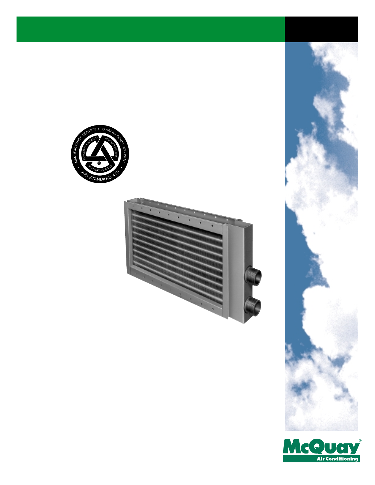
Catalog
413-4
McQuay®Steam Coils
Types HI-F5, HI-F8 & E-F5
Page 2
HI-F5, HI-F8 & E-F5 steam coils HI-F5, HI-F8 & E-F5 steam coils
SelectTOOLSTM for
Contractor Coils
McQuay offers an unmatched variety of standard fin spacings,
row and circuiting combinations. For optimum coil selection,
McQuay's SelectTOOLSTM for Contractor Coils selection program makes it easy to select the most economical standard or
special application coil to meet your job requirements.
Contact your local McQuay representative for a coil selection
that meets the most exacting specification.
ARI certification
McQuay steam coils are certified in accordance with the forced
circulation air cooling and air heating
coil certification program, which is
based on ARI Standard 410.
To obtain ARI certification ratings, it is
first necessary to have the testing facilities reviewed for proper instrumentation, control and accuracy of test data.
A coil is then submitted to an ARI
approved independent testing facility
for comparative tests. ARI then
approves the coil manufacturer’s testing facilities. After the testing facilities are approved, the coil is tested over a wide range
of operating conditions. All rating data is the reviewed by ARI
engineers for accuracy and confirmation that procedures established by ARI have been followed. Periodic check lists of production coils by ARI, on a random basis, assures compliance
with ARI standards.
SelectTOOLSTM.........................................................1
ARI certification..........................................................1
Nomenclature .............................................................2
Standard availability chart......................................3, 4
Design features ......................................................3, 4
Steam circuiting arrangements ..................................5
General specifications ...............................................6
Coil selection considerations......................................7
Sample coil selection and general formulas...............8
Conversion of air volume to standard air ...................9
Capacity data ...........................................................10
Hl-F5 capacity curves...............................................10
E-F5 capacity curves................................................11
HI-F8 capacity curves............................................. 12
Condensate loading factors .....................................13
Air pressure drop..................................................... 14
Coil selection data ................................................... 16
Dimensional data .................................................... 17
Piping data.............................................................. 19
Engineering guide specifications............................. 21
Note: special application coils may be outside the scope of ARI
Standard 410.
“McQuay" and "HI-F" are registered trademarks of McQuay International, Minneapolis, MN.
The McQuay HI-F fin surface is covered by U.S. Patent No. 3,645,330.
Copyright © 2001 McQuay International. All rights reserved throughout the world.
Bulletin illustrations cover the general appearance of McQuay International products at time of publication
and we reserve the right to make changes in design and construction at any time without notice.
Catalog 413 / Page 1
Page 3
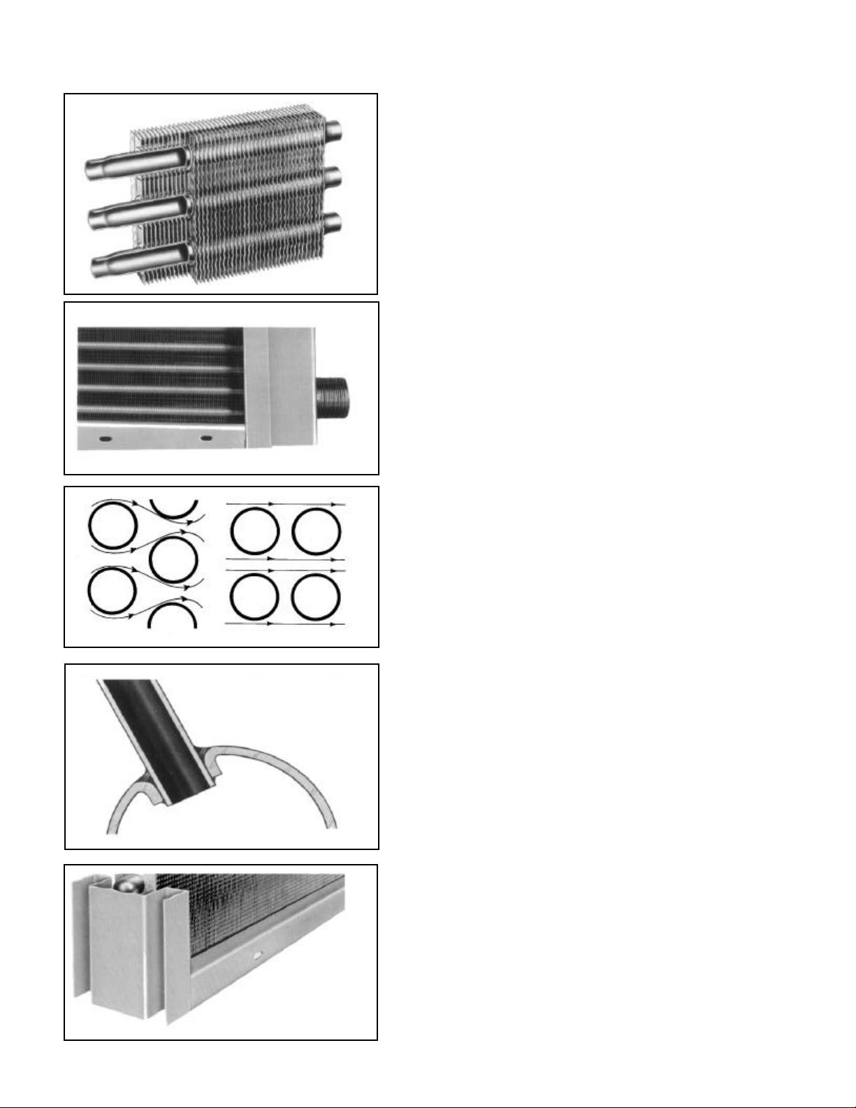
A pioneer in corrugated fin development A pioneer in corrugated fin development
HI-F Means High Efficiency
A principal factor governing fin heat transfer efficiency is the
boundary layer film of air adhering to any fin surface. This
boundary layer insulates the fin, severely reducing the rate
of heat exchange.
The advanced rippled-corrugated HI-F design creates a
state of continuous turbulence which effectively reduces the
boundary layer formation. The exclusive rippled edge
instantly deflects the incoming air to create initial turbulence.
A succession of corrugations across the fin depth, in conjunction with the staggered tubes, increases the turbulating
effect and eliminates the "dead spots" behind the tubes. In
this manner, the HI-F design establishes a high standard in
heat transfer efficiency yielding sharply increased performance. The rippled fin edge also strengthens the fin edge
and provides a pleasing overall appearance.
E-F Means Energy Efficient
The term "energy efficient," which is used to describe how
well a system utilizes energy, has become a common
expression in the HVAC industry.
With costs of energy rising, the need for cutting operating
expenses is apparent. Lowering the air pressure drop
across the face of the coil will reduce the fan brake horsepower requirement and fan motor electrical demand. The
need to cut operating energy expenses is met by the E-F fin
surface. The smoother fin design of the E-F surface results
in lower operating costs over the life of the equipment.
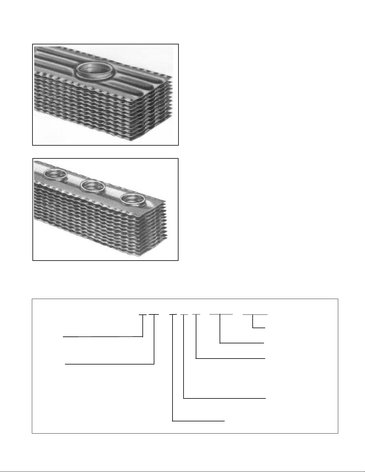
NomenclatureNomenclature
TUBE O.D.:
5 = 5/8 inch
8 = 1 inch
COIL TYPE:
5SA = Single tube, opposite end
5JA,8JA = Distributing tube, same end
8RA = Distributing tube, opposite end
5HA = High pressure construction,
5GA,8GA = High pressure construction,
8TA = High pressure construction,
Page 2 / Catalog 413
connection
connection
connection
single tube, opposite end connection
distributing tube, same end connection
distributing tube, opposite end connection
5 SA - 12 02 C - 033.00 - 090.00
FINS PER INCH:
HI-F5, E F5 (06, 07, 08, 09, 10, 11, 12, 13, 14)
HI-F8 (03, 04, 05, 06, 07, 08, 09, 10, 11, 12, 13, 14)
FINNED LENGTH (INCHES)
FIN HEIGHT (INCHES)
FIN DESIGN:
B = 01 & 02 ROW E-F5
C = 01 & 02 ROW HI-F5
B = 01 ROW HI-F8 (1”)
ROWS DEEP:
HI-F5, E-F5 (01, 02)
HI-F8 (01)
Page 4
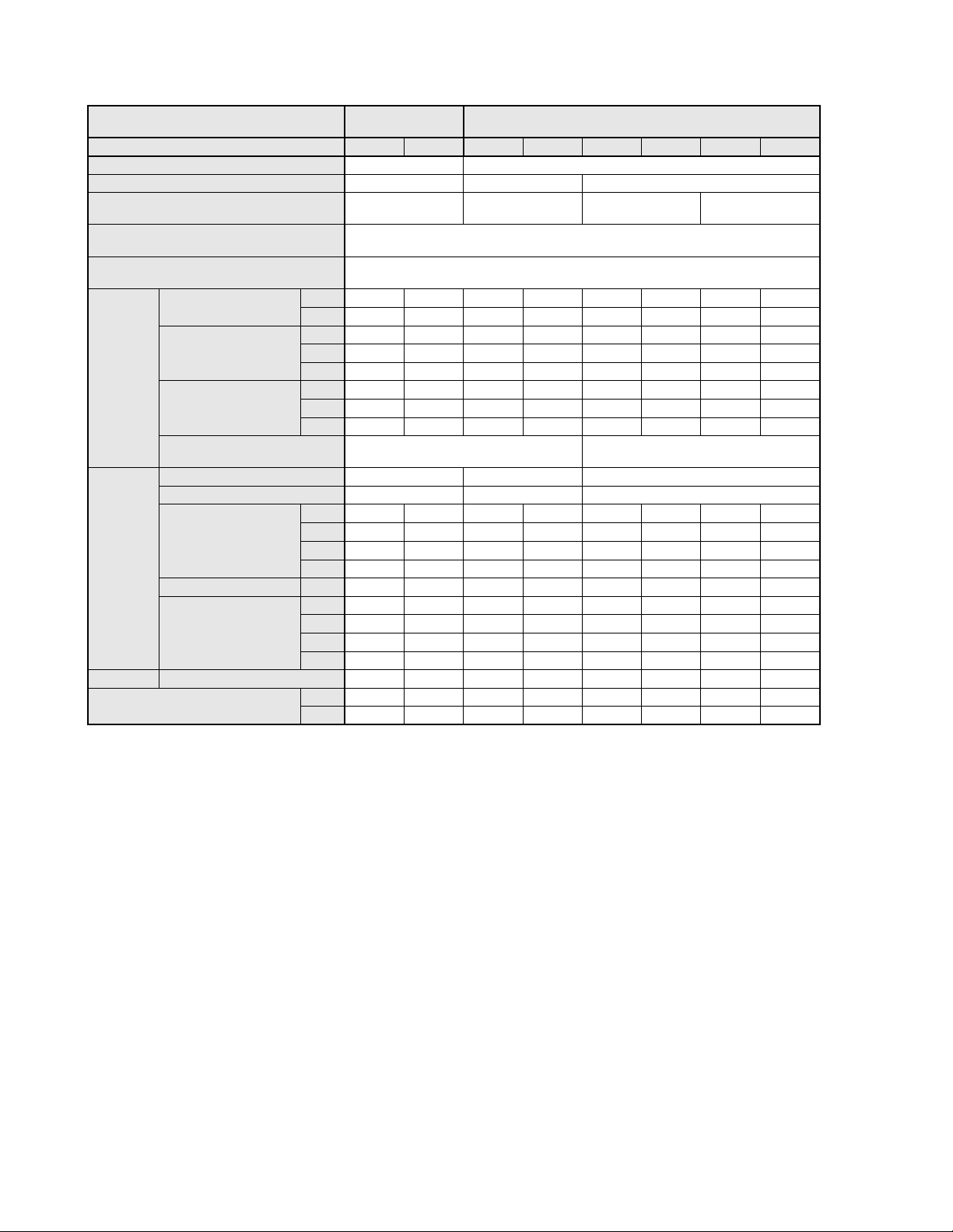
Standard availability chart Standard availability chart
COIL TYPE
COIL MODEL 5SA 5HA 5JA 5GA 8JA 8GA 8RA 8TA
SERPENTINE CIRCUIT Does not apply Does not apply
ROWS 1,2 1,2 1
CONNECTION
LOCATION
FIN HEIGHT
3" INCREMENT
FINNED LENGTH
1-1/2" INCREMENT
FIN TYPE
ALUMINUM
FINS
COPPER
SPACING
(FPI)
DIAMETER 5/8 5/8 1
FACE C/C 1.5 1.5 3.0
COPPER
TUBING
ADMIRALTY BRASS .049 ll ll
CUPRO-NICKEL
HEADERS STANDARD MAT'L Copper Cu Ni Copper Cu Ni Copper Cu Ni Copper Cu Ni
MAXIMUM STD.
OPERATING LIMITS
HI-F
E-F
.0075
.0095
.0120
.006 ll
.0075 ll
.0095 ll
.020
.025
.035
.049 ll ll ll ll
.020 ll ll
.032 ll ll
.035 ll ll
.049 ll ll ll ll
P 150 Psig 350 Psig 150 Psig 350 Psig 150 Psig 350 Psig 150 Psig 350 Psig
T 366 F 450 F 366 F 450 F 366 F 450 F 366 F 450 F
STEAM
(SINGLE TUBE)
Opposite End Same End Same End Opposite End
12-42
12-129
ll ll ll ll
ll ll ll ll
ll ll ll ll
ll ll ll
ll ll ll ll* ll* ll* ll*
ll ll ll ll* ll* ll* ll*
6,7,8,9,10,11,12,13,14 3,4,5,6,7,8,9,10,11,12,13,14
ll
ll
ll
ll
ll ll ll
ll
STEAM
(DISTRIBUTING TUBE)
ll ll ll ll
ll* ll* ll* ll*
ll ll ll
ll
ll Feature Available
* Requires 6 fins per inch or more.
Flexibility
Along with the standard offerings, optional materials and special configurations are provided to meet many different specifications. Extra long finned lengths, intermediate tube supports, along with a wide variety of tube wall and fin thicknesses are available. Casings can be constructed of galvanized steel, aluminum, stainless steel or copper. Optional connection materials such
as steel, red brass or copper (sweat) are offered along with butt-weld, victaulic or flange type connections. Coil coatings can be
phenolic or Electro Fin. These are just a few of the options and specials that can be provided. Consult your local representative
for your special coil requirements.
*Note: Special application coils may be outside the scope of ARI standard 410.
Catalog 413 / Page 3
Page 5
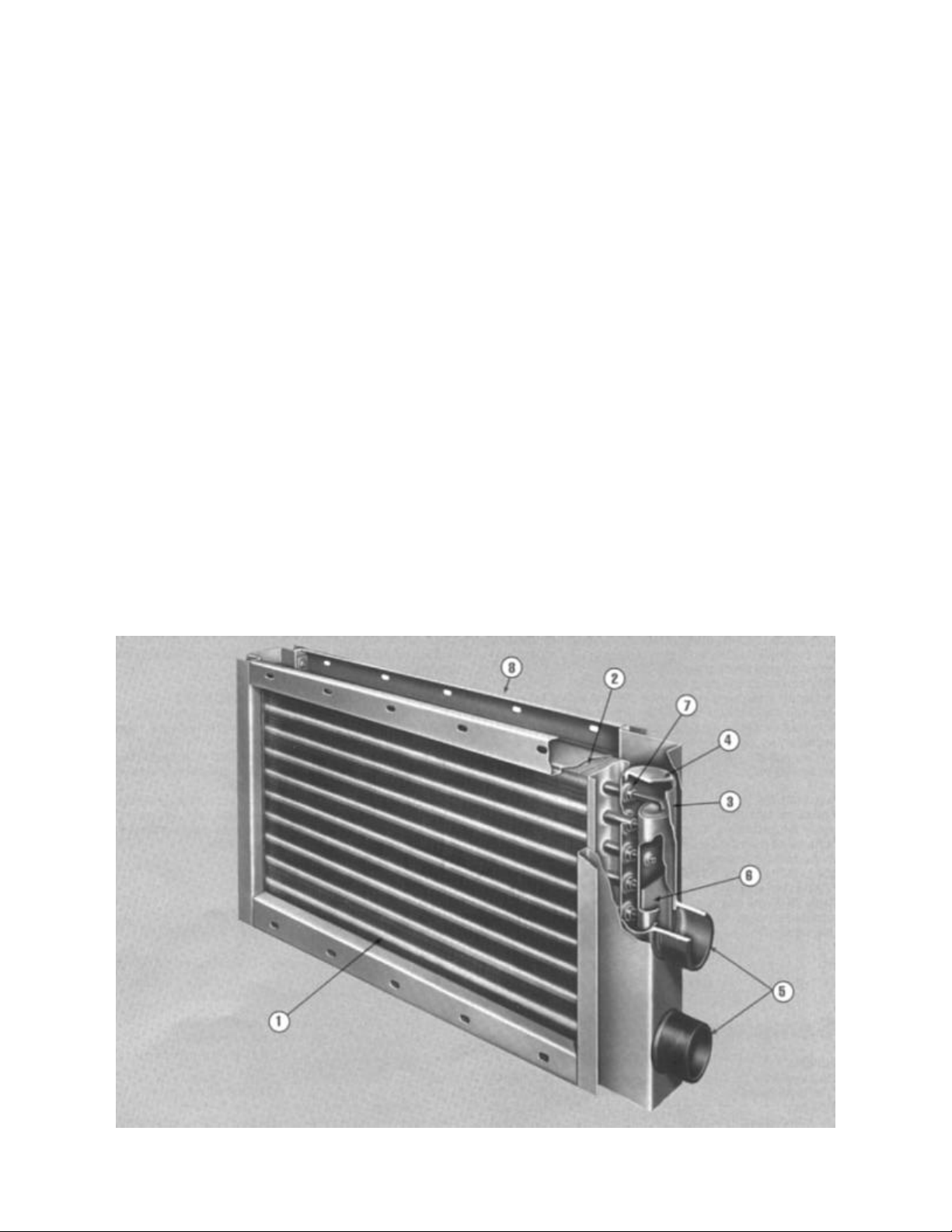
Design features
PATENTED FIN DESIGNS
The HI-F and E-F fin surfaces give the flexibility needed to perform at optimum efficiency. Seamless drawn copper tubes are
mechanically expanded into full drawn, die-formed fin collars to
provide positive metal-to-metal contact for high heat transfer
efficiency and long coil life.
PITCHED IN THE CASING
The specially designed casing automatically provides the
proper pitch for positive condensate removal resulting in
reduced installation and expense. Supply and return connections are properly sized for each coil to assure optimal distribution and proper condensate removal.
STAGGERED TUBE DESIGN FOR HIGH PERFORMANCE
The more moving air in contact with tubes in the coil, the more
performance obtained from the total available surface. The
staggered tube design exposes the tubes to more moving air
than the in-line design. The geometry of the staggered design
also allows the rows to be spaced closer together. This results
in a more compact coil providing higher capacities.
BRAZED COPPER TUBES-TO-COPPER HEADER JOINT
Seamless copper tubes brazed into heavy-gauge seamless
drawn copper headers. This combination of similar metals eliminates unequal thermal expansion and greatly reduces stress in
the tube-header joint. Intruded tube holes in the header allow
an extra large mating area for increased strength and flexibility
designed to provide many years of trouble-free service.
FREE FLOATING CORE
One of the most important requirements of a steam coil design
is to allow for thermal expansion without creating stress and
wear on the tubes.
To provide for this requirement, the coil core must be free to
expand and contract within the casing without inducing wear
on the tubes. A special coil casing has been designed in which
the coil core is free to float in a recessed fin channel. Since the
core is not supported by the tubes there is no resultant tube
wear. The recessed fin channel prevents air bypass while adding structural support to the casing.
Page 4 / Catalog 413
Page 6
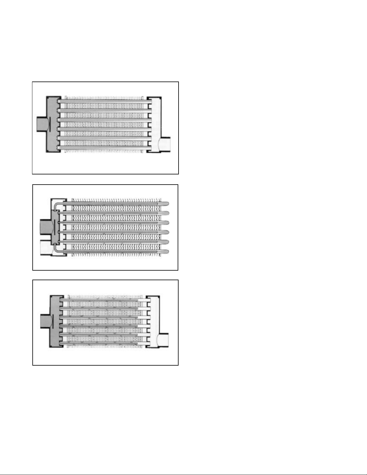
Steam circuiting arrangements Steam circuiting arrangements
Select Hl-F5, E-F5 and HI-F8 steam coils from three different circuiting arrangements: the general purpose 5SA coil, and two jet
tube steam distributing styles-5JA, 8JA and 8RA coils-intended for both general and special purpose heating. While each of
these arrangements has been carefully designed to serve a particular area in steam coil application, sufficient similarities are
present in design and performance to render them interchangeable in many cases. Optimal fin design provides a high performing heat transfer surface while a host of exclusive features provide extended coil life.
5SA & 5HA GENERAL PURPOSE STEAM COILS
5SA and high pressure 5HA steam coils are specifically
designed for economical general purpose heating. Featuring high quality and high capacity, they are an ideal choice
for all regular steam applications - heating, reheating,
booster and process use.
The sectional diagram illustrates the steam circuiting of
this single tube design. A perforated plate type steam baffle directly behind the supply connection ensures even
steam pressure across the entire header length. Inlet tube
orifices meter a uniform flow of steam into each tube.
5JA, 8JA, 5GA & 8GA
JET TUBE DISTRIBUTING COILS
5JA, 8JA and high pressure 5GA and 8GA jet tube steam
distributing coils are excellent for any general purpose
heating application. With the superior freeze resistance
provided by the tube-within-a-tube construction, they are
ideal for low temperature preheating and special process
applications.
The construction, as illustrated, features directional orificed inner tubes, a unique elliptical supply header located
inside the heavy-duty return header and a circuiting
arrangement which provides both supply and return connections at the same end of the coil.
8RA & 8TA OPPOSITE END CONNECTION
JET TUBE DISTRIBUTING COILS
8RA and high pressure 8TA jet tube steam distributing
coils are very similar in design and operation to the "JA"
coils except that supply and return connections are
located on opposite ends.
The directional orifices properly meter steam along the
entire tube length to assure a consistent temperature rise
across the full coil face and accelerate condensate
removal. This important feature is standard on all of our jet
tube steam distributing coils.
Catalog 413 / Page 5
Page 7
General specifications General specifications
1. PRIMARY SURFACE
5/8” O.D. and 1” O.D. round seamless copper tubes.
Cupro-nickel tubes are used for high pressure construction. Tubes are mechanically expanded to provide a continuous compression bond to the fins.
2. SECONDARY SURFACE
HI-F5, E-F5 and HI-F8 rippled-corrugated aluminum dieformed plate type fins. Fin collars are full drawn to provide
accurate control of fin spacing and maximum contact with
tubes.
3. HEADERS
Extra-heavy seamless copper tubing with intruded tube
holes. Provides flexibility for uneven stress during coil
expansion and contraction. Cupro-nickel used for high
pressure construction.
4. HEADER END CAPS
Heavy-gauge, die-formed copper. Monel used for high
pressure construction.
5. CONNECTIONS
Steel male pipe supply and return connections properly
sized for coil capacity. Other materials available on
request. (Red brass connections recommended for coils
used with non-ferrous piping.)
6. STEAM BAFFLES
Supply header baffle disperses entering steam. Prevents
blow-through or short circuiting and ensures equal steam
distribution to all coil tubes.
7. BRAZING
All core joints are brazed with copper brazing alloys.
Headers have intruded tube holes which provide maximum brazing surface and ensure lasting strength.
8. CASINGS
Die-formed heavy-gauge continuous galvanized steel
with reinforced flanges and 3/8” x 3/4” slots on 6” centers for easy mounting. Fin channels brace the core
assembly in the casing, preventing air bypass and
damage in handling.
9. PITCHED IN CASING
Coil cores are pitched in the casing toward the return
connection for horizontal airflow. Provides proper condensate drainage and ease of installation.
10. FREE FLOATING CORE
Design permits coil core to “float” free in the coil casing
during expansion and contraction.
11. TESTS
Complete coil tested leak free at 315 psig air pressure
under warm water containing special wetting agent.
12. OPERATING CONDITIONS
Standard coils rated up to 150 psig and up to 366°F
temperatures. High pressure coils up to 350 psig and
450°F. When steam pressure is above 25 psig, high
pressure coils are recommended for longer coil life.
Page 6 / Catalog 413
Page 8

Coil selection considerations Coil selection considerations
Because we offer a wide variety of steam coil types, materials and fin spacings, you can obtain a very accurate selection. To obtain proper selection of each coil, the following
variables should be considered.
ENTERING AIR TEMPERATURE
Two basic types of steam coils are offered - the single tube
steam coil and the jet distributing tube steam coil.
The single tube steam coil, type 5SA, is generally more
economical when applied in an above freezing environment.
When the entering air is near or below freezing, the jet distributing tube steam coils, types 5JA or 8JA, should be
selected to provide maximum resistance to coil freeze-up.
LEAVING AIR TEMPERATURE
The selection of a coil to deliver a desired leaving air temperature is relatively simple, as it involves only dry bulb temperatures and sensible heating. Steam coils may be accurately
selected to deliver the desired leaving air temperature by
varying the fin series and number of rows deep. In the interest of coil economy, the higher fin series should be used in
place of additional rows deep. However, in some instances,
the system air pressure drop and/or condensate loading may
dictate the use of a lower fin series and more rows deep.
Note: Oversized steam coils can present a control problem. Coils should be sized as accurately as possible.
OPERATING STEAM PRESSURES
Standard steam coil construction is designed to withstand
operating pressures up to 150 psig and give very satisfactory
service. However, the primary factors in coil life are erosive
and corrosive actions, both of which are greatly accelerated
with increased steam pressures. Corrosive action may be
partially controlled by using compounds that will maintain the
proper pH in the system. However, the best protection to prolong coil life is to use heavy-duty high pressure steam coil
construction. Although high pressure construction is not necessary up to 150 psig, it is highly recommended for longer
coil life and coil economy when operating steam pressures
exceed 25 psig.
LOWERING AIRSIDE PRESSURE DROP
The E-F5 fin is designed to lower the air pressure drop
from 20% to 30% for a given application. Although more
surface may be necessary to maintain capacity, the cost
can be amortized by the lower fan brake horsepower
requirements. The payback may be realized in just a few
months.
FREEZING CONDITIONS
When the entering air to the coil is below freezing, the use
of coils in series airflow and the correct control system is
the best protection against coil freeze-up. In such a system, the first coil in the direction of airflow would use a
two-position control valve that would open to full steam
pressure (5 psig minimum) whenever the outside air temperature drops below freezing and would be capable of
raising the entering air from the minimum expected outside temperature to at least 35° F. The second coil would
use a modulating control valve and would raise the entering air up to the final required leaving air temperature. By
using this type of system, the first coil could not freeze,
because it would always be in full operation when the
entering air temperature is below 35°F. The second coil
could not freeze because the entering air temperature
would always be above 35°F.
For ease of control and maximum freeze protection, the
use of an additional preheat coil is recommended when
the entering air temperature is expected to drop well below
freezing. In such a system, the first coil would be the
smallest and would open at 35°F. The second coil would
open at about 10°F to 15°F outside air temperature,
depending on the capacity of the first coil. A third coil
would be modulated to obtain the final leaving air temperature.
In calculating the air temperature rise through the second and third coil, the leaving air temperature off the first
coil is used as the entering air temperature to the second
coil, etc.
For additional recommendations regarding freezing conditions, refer to page 19.
AIR VOLUME (CFM)
The CFM to be handled will be determined by the consideration of the installation. The coil size selected must be capable of handling the total CFM at face velocities (FPM)
acceptable to the heating application. Face velocities may
range from 200 to 1500 FPM with 600 to 700 FPM a common design range.
When the specified air volume is not at standard air conditions, 70°F and sea level, the CFM must be corrected, as
Illustrated on page 9, before using the curves and tables in
this catalog.
Sample coil selection
BTUH required...................................................... 1,830,000
CFM (standard air)..................................................... 24,000
Coil face................................................................36” x 120”
Saturated steam pressure..........................................10 psig
Entering air temperature.............................................-10° F
Coil type..............................................HI-F Single Tube Coil
INDIVIDUAL INSTALLATION REQUIREMENTS
Each installation will have its own particular requirements.
Normally one of the wide variety of our steam coils will
conveniently fill these requirements without modification.
If the application is to be zoned, the uniform air temperature distribution of types 5JA, 8JA and 8RA makes these
coils well suited.
Where problems such as special controls, atmosphere
contamination, special process applications, etc., indicate
the need for a special coil, contact your local representative. This individual welcomes the opportunity to assist you.
Coil face area: FA = 36 x 120 = 30.0 sq. ft.
144
Coil face velocity: FV = CFM = 24,000 = 800 FPM
FA 30.0
Catalog 413 / Page 7
Page 9

TR/ITD METHOD:
1. Determine TR/ITD:
TR = Lvg. Air - Ent.Air = BTUH
1.09 x CFM
1,830,000 = 70°F
1.09 x 24,000
ITD = Sat. Steam Temp. - Ent. Air Temp.
Sat. Steam Temp. = 239.4 (Table 2, page 16)
TR/ITD = 70 = 0.281
239.4 - (-10)
2. Initial Selection
Enter Figure 3 at 800 FPM to determine which coil meets
or exceeds a TR/ITD of 0.281. A 5SA1001C coil has a
TR/lTD of 0.292.
3. Determine Condensate Loading Factor (FL)
BASE TEMPERATURE RISE METHOD:
1. Determine Air Temperature Rise
TR = BTUH = 1,830,000 = 70°F
1.09 x CFM 1.09 x 24,000
2. Determine Steam Conversion Factor (FS)
FS = 1.098 (Table 1, page 16)
3. Determine Condensate Loading Factor (FL)
Condensate Loading = BTUH
Assume 1-row coil. If 1-row coil does not meet required
capacity, the following steps should be repeated for a 2row coil:
Latent Heat x Tubes Fed
Latent Heat = 952.6
(Table 2, page 16)
Condensate Loading = BTUH
Latent Heat = 952.6 (Table 2, page 16)
Tubes Fed = 24 (Table 3, page 16)
1,830,000 = 80.0 Lb./Hr./tube
952.6 x 24
Enter Figure 6 at 80.0 lbs./hr./tube and 10 psig to find
FL = 0.995.
4. Final Selection
Actual TR/ITD = 0.292 x 0.995 = 0.290 (greater than 0.281)
Final Selection: 5SA1001C - 36 x 120
5. Air Pressure Drop
Refer to Figure 12 and find air pressure drop of 0.37” H20.
6. Determine Actual Condensate Loading
Actual TR = 0.290 x [239.4 - ( - 10)] = 72.3
Actual BTUH = (1.09)(24,000)(72.3) = 1,892,000
Actual Condensate Load = BTUH
1,892,000 = 1986 Lb./Hr.
7. Determine Actual Leaving Air Temperature
Actual Lvg. Air Temp. = Ent. Air Temp. + TR
= (-10) + 72.3 = 62.3°F
Latent Heat x Tubes Fed
Latent Heat
952.6
Tubes Fed = 24 (Table 3, page 16)
1,830,000 = 80.0 Lb./Hr./tube
952.6 x 24
FL = 0.995 (Figure 6)
4. Determine Base Temperature Rise Required
Base Temp. Rise Required = Air Temp. Rise
FT x F
70 = 64.1°F
1.098 x 0.995
5. Coil Selection
Enter Figure 3 at 800 FPM to determine which coil
meets or exceeds a base temperature of 64.1°F A
5SA1001C coil has a base temperature of 66.2° F.
Final Selection: 5SA1001C - 36 x 120.
6. Air Pressure Drop
Refer to Figure 12 and find air pressure drop of
0.37” H20.
7. Actual Condensate Loading
Actual TR = Base x FT x F
66.2 x 1.098 x 0.995 = 72.3
Actual BTUH (1.09)(24,000)(72.3) = 1,892,000
Actual Condensate Load = BTUH
Latent Heat
1,892,000 = 1986 lb/hr.
952.6
L
L
General formulas
1. BTUH: BTUH = 1.09 x CFM x Temperature Rise
Where: 1.09 = 0.242 x 60 x 0.075
0.242 = Sp. Ht. of Air at 70°F
60 = Min./Hr.
0.075 = Density Std. Air in Lbs./Cu.Ft.
Temp. Rise = Lvg. Air Temp. - Ent. Air Temp.
2. Temperature Rise (TR): TR = BTUH
1.09 x CFM
3. Leaving Air Temperature
Lvg. Air Temp. = Ent. Air Temp. + Temp. Rise
4. Initial Temperature Difference (ITD):
Page 8 / Catalog 413
5. Face Velocity (FPM):
FPM = CFM
Face Area (Sq. Ft.)
6. Pounds Condensate:
Lbs. Cond./Hr. = BTUH
Latent Heat of Steam
7. Condensate Loading:
Lbs. Cond./Hr./Tube = BTUH
Latent Heat of Steam x No. Tubes Fed
Page 10

Conversion of air volume to standard air Conversion of air volume to standard air
Figure 1. Temperature Conversion Factor
When the specified air volume
(CFM) is given at any temperature
other than 70°F or any altitude
other than sea level, these charts
should be used for correction
before using the capacity and pressure drop tables which are based
on CFM at standard air conditions.
EXAMPLE:
To convert 15,900 CFM of air at
95°F and at 3,000 feet altitude to
standard conditions:
CFM of Standard Air
= (CFM of Specified Air x F
= 15,900 x 0.955 x 0.896
= 13.600
x FA )
T
Where:
FT = Temperature Conversion Factor
FA = Altitude Conversion Factor
The CFM of standard air should be
used to determine face velocity
through the coil, which in turn is
used to determine heat transfer values, and the air pressure drop
through the coil.
The air pressure drop value taken
from Figures 12, 13, and 14 must
be converted to altitude to be used
for static pressure calculations. To
convert the air pressure drop from
standard air at sea level to the air
pressure drop at altitude use the
following equation:
Pressure Drop = Pressure Drop at Sea Level
at Altitude FT x F
A
1.30
1.25
1.20
1.15
1.10
1.05
1.00
0.95
0.90
0.85
0.80
TEMPERATURE CONVERSION FACTOR
0.75
0.70
0.65
Figure 2. Altitude Conversion Factor
1.025
1.000
0.975
0.950
0.925
0.900
0.875
0.850
0.825
0.800
0.775
ALTITUDE CONVERSION FACTOR
0.750
0.725
0.700
-500 0 500 1500 2500 3500 4500 5500 6500 7500
TEMPERATURE CONVERSION FACTOR - F
-50 -25 0 25 50
ALTITUDE CONVERSION FACTOR - F
75
ALTITUDE (FEET ABOVE SEA LEVEL)
125 150 175 200 225 250 275 300 325 350
100
TEMPERATURE (°F)
T
1.30
1.25
1.20
1.15
1.10
1.05
1.00
0.95
0.90
0.85
0.80
TEMPERATURE CONVERSION FACTOR
0.75
0.70
0.65
A
8500
1.025
1.000
0.975
0.950
0.925
0.900
0.875
0.850
0.825
0.800
0.775
ALTITUDE CONVERSION FACTOR
0.750
0.725
0.700
Catalog 413 / Page 9
Page 11

Capacity data Capacity data
Figure 3. Steam Capacity Curves for HI-F5 Coils - 5SA & 5HA*
CAPACITY FOR ODD FIN SPACINGS MAY BE FOUND BY INTERPOLATION
.90
HI-F5HI-F5
.80
180
170
.60
.70
.50
.40
.30
FPI & ROWS 1402
FPI & ROWS 1202
FPI & ROWS
1002
FPI & ROWS
0802
FPI & ROWS
FPI & ROWS
FPI & ROWS
FPI & ROWS
FPI & ROWS
FPI & ROWS
0602
1201
1001
0801
160
150
140
130
120
110
100
1401
90
80
70
BASE TEMPERATURE RISE (°F) AT 5 PSIG & 0°F ENTERING AIR
60
0601
.20
TR/ITD AIR TEMPERATURE RISE/DEGREE TEMPERATURE DIFFERENCE BETWEEN STEAM AND ENTERING AIR
.10
300
* 5J/G coils may have slightly less capacity than shown. Use SelectTOOLSTM for Contractor Coils Program for optimum selection.
500
700
STANDARD AIR FACE VELOCITY, FT/MIN.
900
1100 1300 1500
Page 10 / Catalog 413
50
40
30
20
10
Page 12

Figure 4. Steam Capacity Curves E-F5 Coils - 5SA & 5HA*
CAPACITY FOR ODD FIN SPACINGS MAY BE FOUND BY INTERPOLATION
.90
.60
.80
.70
.50
.40
E-F5
FPI & ROWS 1402
FPI & ROWS
1202
FPI & ROWS
1002
FPI & ROWS
0802
180
170
160
150
140
130
120
110
100
90
80
.30
.20
TR/ITD AIR TEMPERATURE RISE/DEGREE TEMPERATURE DIFFERENCE BETWEEN STEAM AND ENTERING AIR
.10
300
* 5J/G coils may have slightly less capacity than shown. Use SelectTOOLSTM for Contractor Coils Program for optimum selection.
500
700
STANDARD AIR FACE VELOCITY, FT/MIN.
FPI & ROWS
FPI & ROWS
FPI & ROWS
FPI & ROWS
FPI & ROWS
900
1401 & 0602
1201
1001
0801
0601
1100 1300 1500
Catalog 413 / Page 11
70
60
50
40
30
20
10
BASE TEMPERATURE RISE (°F) AT 5 PSIG & 0°F ENTERING AIR
Page 13

Figure 5. Steam Capacity Curves for HI-F8 Coils - 8JA, 8RA, 8GA & 8TA
CAPACITY FOR ODD FIN SPACINGS MAY BE FOUND BY INTERPOLATION
.90
HI-F8HI-F8
.80
180
170
.70
.60
.50
.40
FPI & ROWS 1401
.30
.20
TR/ITD AIR TEMPERATURE RISE/DEGREE TEMPERATURE DIFFERENCE BETWEEN STEAM AND ENTERING AIR
.10
FPI & ROWS
FPI & ROWS
FPI & ROWS
FPI & ROWS
FPI & ROWS
FPI & ROWS
1201
1001
0801
0601
0401
0301
160
150
140
130
120
110
100
90
80
70
BASE TEMPERATURE RISE (°F) AT 5 PSIG & 0°F ENTERING AIR
60
50
40
30
20
300
* 5J/G coils may have slightly less capacity than shown. Use SelectTOOLSTM for Contractor Coils Program for optimum selection.
Page 12 / Catalog 413
500
700
STANDARD AIR FACE VELOCITY, FT/MIN.
900
10
1100 1300 1500
Page 14

Condensate loading factors Condensate loading factors
Figure 6. 5SA & 5HA Coils
1.00
L
100
.95
.90
CORRECTION FACTOR, F
.85
0
20 40
Figure 7. 5JA & 5GA Coils
1.00
L
.95
.90
CORRECTION FACTOR, F
.85
0
PSIG 2
20 40
PSIG 2
60 80 100
CONDENSATE LOADING, LB/HR/TUBE
5
60 80
CONDENSATE LOADING, LB/HR/TUBE
5
10
100 120
15
120
20
10
140
25
140
30
15
160
160
50
30
25
20
180 200 220 240
100
50
180 200 220 240
Figure 8. 8JA, 8RA, 8GA & 8TA Coils
1.00
L
.95
.90
CORRECTION FACTOR, F
.85
20
0
40
PSIG 2
60 80
CONDENSATE LOADING, LB/HR/TUBE
5
100 120
10
140
15
20
160
100
50
30
25
180 200 220 240
Catalog 413 / Page 13
Page 15

Air pressure drop Air pressure drop
Figure 12. 5SA, 5HA, 5JA & 5GA Coils Figure 13. 8JA, 8GA & 8RA Coils
HI-F5
HI-F8
NOTE: Air pressure drop for odd fin spacings may be found by interpolation.
Page 14 / Catalog 413
Page 16

Figure 14. 5SA, 5HA, 5JA & 5GA Coils
E-F5
NOTE: Air pressure drop for odd fin spacings may be found by interpolation.
Catalog 413 / Page 15
Page 17

Coil selection dataCoil selection data
Table 1. Steam Conversion Factors (FS)
ENT.
AIR
TEMP
-20 1.021 1.050 1.088 1.142 1.187 1.227 1.263 40 0.757 0.786 0.824 0.878 0.923 0.963 0.999
-15 0.999 1.028 1.066 1.120 1.165 1.205 1.241 45 0.753 0.764 0.802 0.856 0.901 0.941 0.977
-10 0.977 1.003 1.044 1.098 1.143 1.183 1.219 50 0.713 0.742 0.780 0.834 0.879 0.919 0.955
-5 0.955 0.984 1.022 1.076 1.121 1.161 1.197 55 0.691 0.720 0.758 0.812 0.857 0.897 0.933
0 0.933 0.962 1.000 1.054 1.099 1.139 1.175 60 0.669 0.698 0.736 0.790 0.835 0.875 0.911
5 0.911 0.940 0.978 1.032 1.077 1.117 1.153 65 0.647 0.676 0.714 0.768 0.813 0.853 0.889
10 0.889 0.918 0.856 1.010 1.055 1.095 1.131 70 0.625 0.654 0.692 0.746 0.791 0.831 0.867
15 0.867 0.896 0.934 0.988 1.033 1.073 1.109 75 0.603 0.632 0.670 0.724 0.769 0.809 0.845
20 0.845 0.874 0.912 0.966 1.011 1.051 1.087 80 0.581 0.610 0.648 0.702 0.747 0.787 0.823
25 0.823 0.852 0.890 0.944 0.989 1.029 1.065 85 0.559 0.588 0.626 0.680 0.725 0.765 0.801
30 0.801 0.830 0.868 0.922 0.967 1.007 1.043 90 0.537 0.566 0.604 0.658 0.703 0.743 0.779
35 0.779 0.808 0.846 0.900 0.945 0.985 1.021 100 0.493 0.522 0.560 0.614 0.659 0.699 0.735
NOTE: To calculate conversion factors not given in the above table, use this formula: Conversion Factor = Saturated Steam Temperature - Entering Air Temperature
227.1
STEAM – PRESSURE – TEMPERATURE – LATENT HEAT
0
212.0°
970.3
0
218.5°
966.1
5
227.1°
960.6
10
239.4°
952.6
15
249.7°
945.6
20
258.8°
939.6
25
266.8°
934.0
ENT.
AIR
TEMP
STEAM – PRESSURE – TEMPERATURE – LATENT HEAT
0
212.0°
970.3
0
218.5°
966.1
5
227.1°
960.6
10
239.4°
952.6
15
249.7°
945.6
20
258.8°
939.6
Table 2. Properties of Saturated Steam, BTU/Lb.
PSIG TEMP.
(°F)
2 218.5 966.1 60 307.3 904.7
5 227.1 960.6 70 316.0 898.0
10 239.4 952.6 80 323.9 891.9
15 249.7 945.7 90 331.2 886.2
20 258.8 939.6 100 337.9 880.8
25 266.8 934.0 125 352.9 868.3
30 274.0 929.0 150 365.9 857.2
40 286.7 919.9 175 377.4 846.9
50 297.7 911.8 200 387.8 837.5
LATENT
HEAT
PSIG TEMP.
(°F)
LATENT
HEAT
25
266.8°
934.0
Table 3. Number of Tubes Fed
COIL TYPE
8JA,8RA,8GA,8TA
5SA,5JA,5HA,5GA
ROWS
1 4 5 6 7 8 9 10 11 12 13 14
1 8 10 12 14 16 18 20 22 24 26 28
2 15 19 23 27 31 35 39 43 47 51 55
Page 16 / Catalog 413
FIN HEIGHT (FH) - INCHES
12 15 18 21 24 27 30 33 36 39 42
Page 18

Dimensional data Dimensional data
Figure 15. 5SA, 5HA, 8RA & 8TA Cased Coils
2.75
AIR
FLOW
LH
RH
AIR
FLOW
B + .500
2.50
5.00
MAX
RETURN
4.062
.375 X .750 SLOTS ON
6.00 C/C FROM CENTER
OF FINNED LENGTH
.750
W- .625
.750
FINNED LENGTH (FL)
FL + 3.00 (OVER FLANGES)
FL + 8.125 (APPROX)
2.75
MAX
SUPPLY
SEE NOTE 6
CD-0601340B-03
2.50
W + 3.00
ONE ROW COIL
TWO ROW COIL
MODEL ROW
SUPPLY
CONN
SIZE
RETURN
CONN
SIZE
B W
5SA, 5HA 01 1-1/2 1-1/2 2.25 12.00 - 18.00
5SA, 5HA 01 2 1-1/2 2.25 21.00 - 42.00
5SA, 5HA 02 2-1/2 2-1/2 2.75 12.00 - 42.00
8RA, 8TA 01 2-1/2 2-1/2 2.75 12.00 - 42.00
Figure 16. 5JA, 5GA, 8JA & 8GA Cased Coils
AIR
RH
FLOW
AIR
LH
FLOW
SEE NOTE 7
B + .500
ONE ROW COIL
5.00
TWO ROW COIL
MODEL ROW
CONN
SIZE
B W
5JA, 5GA 01 2 2.50 12.00 - 42.00
5JA, 5GA 02 2-1/2 2.75 12.00 - 42.00
8JA, 8GA 01 2-1/2 2.75 12.00 - 42.00
2.50
SUPPLY
RETURN
2.50
CD-0601320B-01
GENERAL NOTES:
1. HORIZONTAL AIR FLOW.
2. ALL COILS DRAINABLE.
3. CONNECTIONS ARE PIPE, NPT (EXT.)
4. ALL DIMENSIONS ARE IN INCHES.
5. CONNECTION LOCATION ± .125.
6. .125 TO .562 ABOVE COIL CENTER LINE.
7. TUBES ARE PITCHED TOWARD RETURN CONNECTION.
8. STEAM DISTRIBUTNG INNER TUBES (8RA & 8TA).
.375 X .750 SLOTS ON
2.75
MAX
4.062
6.00 C/C FROM CENTER
OF FINNED LENGTH
.750
W - .625
.750
FINNED LENGTH (FL)
FL + 3.00 (OVER FLANGES)
FL + 5.75 (APPROX)
GENERAL NOTES:
1. HORIZONTAL AIR FLOW.
2. ALL COILS DRAINABLE.
3. CONNECTIONS ARE PIPE, NPT (EXT.)
4. ALL DIMENSIONS ARE IN INCHES.
5. CONNECTION LOCATION ± .125
6. STEAM DISTRIBUTING INNER TUBES.
7. .125 TO .562 BELOW COIL CENTER LINE.
8. TUBES ARE PITCHED TOWARD RETURN CONNECTION.
W + 3.00
NOMENCLATURE: 5 S A
TUBE DIAMETER
5 = 5/8 inch O.D.
8 = 1 inch O.D.
TUBE CENTERS:
A = 1-1/2 inch (except all HIF8 coils are 3” CC)
COIL TYPE:
S = Standard construction, Fig. 15 & 16 with single tube
J = Standard construction, Fig. 15 & 16 with distributing tube
R = Standard construction, Fig. 15 & 16 with distributing tube
H = High pressure construction, Fig. 15 & 16 with single tube
G = High pressure construction, Fig. 15 & 16 with distributing tube
T = High pressure construction, Fig. 15 & 16 with distributing tube
Catalog 413 / Page 17
Page 19

Figure 17. 5SA, 5HA, 8RA & 8TA Uncased Coils
1.469
AIR
LH
FLOW
1/2 W
AIR
RH W
FLOW
MODEL ROW
SEE VIEW A
SUPPLY
DEPTH (2.938)
SUPPLY
CONN
SIZE
ONE ROW COIL
TWO ROW COIL
RETURN
CONN
SIZE
C = CONN. LENGTH
0.40 TYP.
FINNED LENGTH (FL)
A MAX
D MAX
A B D W
RETURN
1.469
5SA, 5HA 01 1-1/2 1-1/2 3.250 1.125 3.250 12.00 - 18.00
5SA, 5HA 01 1-1/2 1-1/2 3.750 1.125 3.250 21.00 - 42.00
5SA, 5HA 02 2-1/2 2-1/2 3.875 1.625 3.875 12.00 - 42.00
8RA, 8TA 01 2-1/2 2-1/2 3.875 1.625 3.875 12.00 - 42.00
=CONN. LENGTH
C
B
VIEW A
NOTCH TYP 4 CORNERS
EACH END FIN
.078
.375
GENERAL NOTES:
1. HORIZONTAL AIR FLOW.
2. ALL COILS DRAINABLE.
3. CONNECTIONS ARE PIPE, NPT (EXT.)
4. ALL DIMENSIONS ARE IN INCHES.
5. CONNECTION LOCATION ± .125.
6. STEAM DISTRIBUTNG INNER TUBES
(8RA & 8TA).
CONN LENGTH
OPTION C
CONTRACTOR 3.00
STD. UNIT 7.00
LINED UNIT 8.50
VISION UNIT 8.50
Figure 18. 5JA, 5GA, 8JA & 8GA Uncased Coils
1.469
1/2 W
AIR
LH
AIR
FLOW
FLOW
B
RH
MODEL ROW
5JA, 5GA 01 2 3.750 1.375 12.00 - 42.00
5JA, 5GA 02 2-1/2 3.875 1.625 12.00 - 42.00
8JA, 8GA 01 2-1/2 3.875 1.625 12.00 - 42.00
SEE VIEW A
SUPPLY
RETURN
1.469
DEPTH (2.938)
CONN
SIZE
C = CONN. LENGTH
W
FINNED LENGTH (FL)
A MAX
ONE ROW COIL
TWO ROW COIL
A B W
NOMENCLATURE: 5 S A
1.125
0.40 TYP.
VIEW A
NOTCH TYP 4 CORNERS
EACH END FIN
.078
.375
CONN LENGTH
OPTION C
CONTRACTOR 3.00
STD. UNIT 7.00
LINED UNIT 8.50
VISION UNIT 8.50
GENERAL NOTES:
1. HORIZONTAL AIR FLOW.
2. ALL COILS DRAINABLE.
3. CONNECTIONS ARE PIPE, NPT (EXT.)
4. ALL DIMENSIONS ARE IN INCHES.
5. CONNECTION LOCATION ± .125
6. STEAM DISTRIBUTING INNER TUBES.
TUBE DIAMETER
5 = 5/8 inch O.D.
8 = 1 inch O.D.
Page 18 / Catalog 413
TUBE CENTERS:
A = 1-1/2 inch (except all HIF8 coils are 3” CC)
COIL TYPE:
S = Standard construction, Fig. 17 & 18 with single tube
J = Standard construction, Fig. 17 & 18 with distributing tube
R = Standard construction, Fig. 17 & 18 with distributing tube
H = High pressure construction, Fig. 17 & 18 with single tube
G = High pressure construction, Fig. 17 & 18 with distributing tube
T = High pressure construction, Fig. 17 & 18 with distributing tube
Page 20

Piping data Piping data
APPLICATION RECOMMENDATIONS
Satisfactory operation and service are best provided when coils
are installed with proper piping, trap, and support arrangement.
The following notes and diagrams are recommended.
General
1. Provide separate supports and hangers for the coil and for
the piping.
2. Be certain that adequate piping flexibility is provided.
Stresses resulting from expansion of closely coupled piping
and coil arrangement can cause serious damage. Coils having opposite end connections must be piped with expansion
joints.
3. Standard coils are pitched in the casings when installed for
horizontal airflow. The installation should be checked to
ensure that the casing is level. On vertical airflow applications, the coils must be pitched when installed.
4. Do not reduce pipe size at the coil return connection. Carry
return connection size through the dirt pocket, making the
reduction at the branch leading to the trap.
5. Install vacuum breakers on all applications to prevent retaining condensate in the coil. Generally, the vacuum breaker is
to be connected between the coil inlet and the return main,
as shown. However, for a system with a flooded return main,
the vacuum breaker should be open to the atmosphere and
the trap design should allow venting of large quantities of air.
6. Do not drip supply mains through the coil.
7. Do not attempt to lift condensate when using modulating or
on-off control.
Traps
1. Size traps in accordance with trap manufacturer’s recommendations. Be certain that the required differential will
always be available. DO NOT UNDERSIZE.
2. Float and thermostatic or bucket traps are recommended for
low pressure steam. On high pressure systems, bucket traps
are normally recommended. The thermostatic traps should
be used only for air venting.
3. Bucket traps are recommended for use with on-off control
only.
4. Locate traps at least 12 inches below the coil return
connection.
5. Multiple coil installation:
a. Each coil or group of coils that is individually controlled
must be individually trapped.
b. Coils in series — separate traps are required for each
coil, or bank of coils, in series.
c. Coils in parallel — a single trap may generally be used
but an individual trap for each coil is preferred.
Controls
1. With coils arranged for series airflow, a separate control is
required on each bank, or coil, in the direction of airflow.
2. On high pressure installations, a two-position steam valve
with a face and bypass arrangement is preferred where
modulating control is required.
3. Modulating valves must be sized properly. DO NOT
UNDERSIZE.
Freezing Conditions
(Entering air temperatures below 35°F)
1. 5JA, 8JA and 8RA coils are definitely recommended.
2. 5 psi steam must be supplied to coils at all times.
3. Modulating valves are not recommended. Control should
be by means of face and bypass dampers.
4. Consideration should be given to the use of two or three
coils in series with two-position steam control valves on
that coil or coils which will be handling 35°F or colder air.
The desired degree of control can be attained with a modulating valve on the downstream coil.
5. Provision should always be made to thoroughly mix fresh
air and return air before it enters coil. Also, temperature
control elements must be properly located to obtain true air
mixture temperatures.
6. As additional protection against freeze-up, the trap should
be installed sufficiently far below coil to provide an adequate hydrostatic head to help remove of condensate during an interruption in the steam pressure. Estimate 3 feet
for each 1 psi of trap differential required.
7. On startup, admit steam to coil ten minutes before admitting outdoor air.
8. Provisions must be made to close fresh air dampers if
steam supply pressure falls below minimum specified.
SYMBOLS FOR PIPING ARRANGEMENTS
LOW PRESSURE (TO 25 PSI)
*5JA or 8JA coil installed with tubes vertical. The
coil supply piping must be dripped ahead of the
coil on an installation of this type.
*5SA coil installed for vertical airflow. Installer
must pitch coil toward the return connection on
vertical airflow installations. For horizontal airflow installation, the required pitch is built into
the casing.
* NOTE: Rating data is ARI certified only for the
standard ARI coil orientation; i.e., horizontal
tubes, vertical coil face and horizontal airflow.
Catalog 413 / Page 19
Page 21

LOW PRESSURE (TO 25 PSI)
5JA or 8JA coil installed in
series. Note that each coil
must have a separate control
valve and trap.
*5SA coils installed with tubes vertical. Diagram
shows single trap; however, it is always preferable
to trap each coil individually.
* NOTE: Rating data is ARI certified only for standard ARI coil orientation; i.e., horizontal tubes,
vertical coil face and horizontal airflow.
HI PRESSURE (OVER 25 PSI)
8RA and 5SA coils banked three high by three
deep. Individual trapping of each coil as shown
is preferred. Note that it is necessary to provide
a separate control valve for each bank in the
direction of airflow.
5GA or 8GA coils. Note the addition of a vacuum
breaker to permit the coil to drain during shutdown.
Page 20 / Catalog 413
8TA or 5HA coils. Condensate is lifted to overhead return main.
Page 22

Engineering guide specifications Engineering guide specifications
Furnish and install as shown on plans and as described in the tabulated specifications, McQuay ARI certified steam
heating coils of extended surface, staggered tube, HI-F or E-F rippled, corrugated plate fin type. Coil performance
should be substantiated by computer generated output data.
HEADERS shall be of non-ferrous materials using seamless copper tubing with intruded tube holes to permit expansion and contraction without creating undue stress. Rolled-in joints or dissimilar metals will not be acceptable. Both
the supply and return headers shall be completely encased by the coil casing. Heating surface tubes shall not pass
through a header end sheet and be subjected to wear of the tubes because of movement which occurs when the
coils expand and contract.
Orificed baffle plates shall be installed in the supply headers opposite the supply connection to provide proper dif-
fusion of the entering steam.
PRIMARY SURFACE shall be round, seamless (5/8” O.D.) (1” O.D.) copper tubing brazed into intruded header tube
holes using brazing alloys. Tubes on two-row coils shall be staggered in the direction of airflow. Tubes shall be on
1-1/2” or 3” centers. High pressure coils shall have cupro-nickel tubes and headers.
SECONDARY SURFACE shall consist of rippled aluminum plate fins (HI-F5, E-F5 or HI-F8) for higher capacity and
structural strength. Fins shall have full drawn collars to provide a continuous surface cover over the entire tube. Fins
shall not have sharp edges which accumulate dirt. Tubes shall be expanded into the fins to provide a continuous primary to secondary compression bond over the entire finned length for maximum heat transfer rates.
CASINGS shall be constructed of continuous galvanized steel. Coil side plates shall be reinforced type for greater
strength and ease of stacking and shall have 3/8” x 3/4” slots on 6” centers for mounting. Full length fin channels
shall be furnished to brace the coil core and prevent air bypass.
Coils shall be pitched in casing for horizontal airflow toward the return header end. A minimum of 1/8” pitch per foot
of coil finned length shall be used to allow proper condensate drainage.
5SA, 5HA, 8RA & 8TA COILS shall have the supply header on one end and return header on the other end. The
supply header end of each coil tube shall be properly orificed to meter the steam uniformly to each tube.
5JA, 5GA, 8JA & 8GA COILS shall have both the supply header and return header on the same end. The supply
header shall be enclosed by the return header and shall feed the inner steam distributing tubes. The coil end opposite the connection end shall be free to float within the casing as expansion and contraction occurs.
TESTS: The complete coil core shall be tested with 315 pounds air pressure under warm water and suitable for
working conditions up to 150 psig and 366° F. High pressure coils shall be suitable for working conditions up to 350
psig and 450 °F. Individual tube tests and core tests before installation of headers are not considered satisfactory.
Hydrostatic tests alone will not be acceptable. Capacities shall be as outlined in the tabulation and substantiated by
computer generated output data.
Suggested Steam Coil Tabulation
TAG NO. QTY. COIL TYPE FIN SERIES ROWS FIN HEIGHT FINNED LENGTH
FACE AREA
MAX. FACE
VELOCITY
CFM
ENT. AIR
TEMP. (°F)
LVG. AIR
TEMP (°F)
PSIG STEAM
MAX. AIR PRESSURE
DROP INCHES OF
WATER
Catalog 413 / Page 21
Page 23

13600 Industrial Park Boulevard, Minneapolis, MN 55441 USA • (800) 432-1342 • www.mcquay.com
 Loading...