

Page 1

AIR COOLED CHILLER
(C Series)
INSTALLATION MANUAL
Group: MINI CHILLER
Part Number: A08019025453
Date: JULY 2003
IM-ACC1&2-0703-McQuay
© 2003 McQuay International
Page 2

Page 3
English
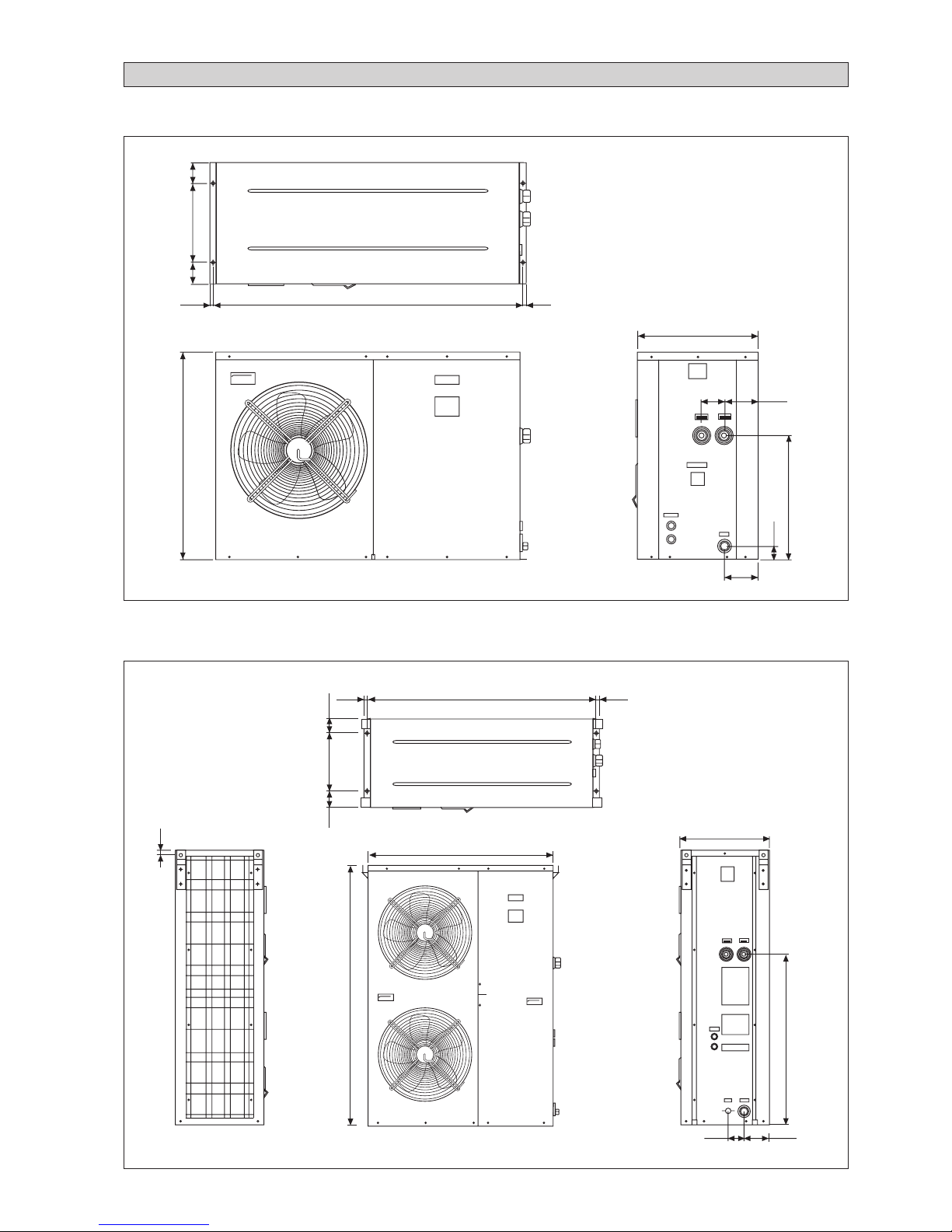
4AC/AC 20/25/30 C/CR
4AC/AC 40/50/60 C/CR
1181,610,0 10,0
460,0
85,0 128,5
WATER
INLET
DRAINAGE
WATER
OUTLET
128,5
789,5
475,0
55,2
80,0 300,0
80,0
1181,6
460,0
85,0
128,5
15,0 15,0
300,079,7
20,0
80,3
116 0,0
1409,4
878,8
WATER
INLET
DRAINAGE
WATER
OUTLET
OUTLINE AND DIMENSIONS
i
Page 4
! Caution
Sharp edges and coil surfaces are potential locations which may cause
injury hazards. Avoid from being in contact with these places.
! Avertissement
Les bords coupants et les surfaces du refroidisseur tuulaire présentent
un risque de blessure. Mieux vaut éviter le contact avec ces endroits.
! Vorsicht
Scharfe Kanten und Wärmetauscherflächen stellen eine Gefahrenquelle dar.
Jeglicher Kontakt mit diesen Stellen ist zu vermeiden.
! Cautela
Per preservarsi da eventuali ferite, evitare di toccare gli spigoli affilali e la
superficie della serpentina.
! Осторожно
Острые края и поверхности змеевиков являются
потенциальными местами нанесения травм. Остерегайтесь
контакта с этими местами.
! Cuidado
Los Bordes afilados y la superficie del serpentín pueden producir lesiones.
Evite tocarlos.
ii
This product is subjected to Waste of Electrical and Electronic Equipment Regulations (WEE
E
Regulations). The waste product shall be separately collected by specific collection and treatment centre
.
P
lease refer to local authorithy for these centres. This is only applicable to European Union countries
.
Ce produit est soumis
à
la r
ééé
é
lectriques e
t
ййкйй
ééé
é
tre ces centres. Ceci
est uniquement applicable aux pays de l'Union Euro
p
é
enne
.
Questo prodottoè soggetto alle disposizioni RAEE (Rifiuti di apparecchiature elettriche ed elettroniche)
.
à
à
locali. Questa disposizione
è
valida solamente i paes
i
dell
U.E.
é
ctrico y Electrnico en materia d
e
fico
de colecc
i
solamente aplicable a los pases de la Un
i
n
Europea
.
Dieses Produkt unterliegt den Bestimmungen zur Entsorgung von elektrischen und elektronische
n
er
tes
ü
ll bei Ihrer
ü
ndiges Abfall-Amt. Dieser
Hinweis gilt nur f
ischen Union
.
Процес
с
у
тилизациианногопродуктарегулируетсяправиламип
о
у
тилизаци
и
отходо
в
(WEEE Regulations).
т
и
правил
а
Европейског
о
NOTICE
Page 5

English
HEAT
OFF
COOL
ON
LIVE
COM2
COM1
BOILER
W_PUMP
OUT_FAN2
4WV2
A_FREEZE
ALM_OUT
ALM_IN
4WV1
OUT_FAN1
AUX-H
12V
F02
F01
LP2
LP1
HP2
HP1
C02
C01
FLOW
PO
ALM
DE2
DE1
C/H
ON/OFF
WI
CN6
WO OA
CD1 CD2DF1 DF2
N
COMP DISCHARGE SENSOR (1)
OUTDOOR AIR TEMP SENSOR
LEAVING WATER SENSOR
ENTERING WATER SENSOR
N/L2
220-240/1pH/50Hz
L/L1TB1
12V 12V 12V N1 N1 N1 1 2 O/F PUMPC/H
4WV
HTR
AL
IN
AL
OUT
LP HP FL
H
T
R
OF
OUT
OF
IN
TB3
L
N
C
OF
C
S
R
E
COMP.
L
N
E
PUMP
FUSE
10A
5B
4B 1A
2A
SWITCH
A
B
COMP
COMP
CAP
98
95
96
C O/L
TB2
OF
CAP
R
R
C
S
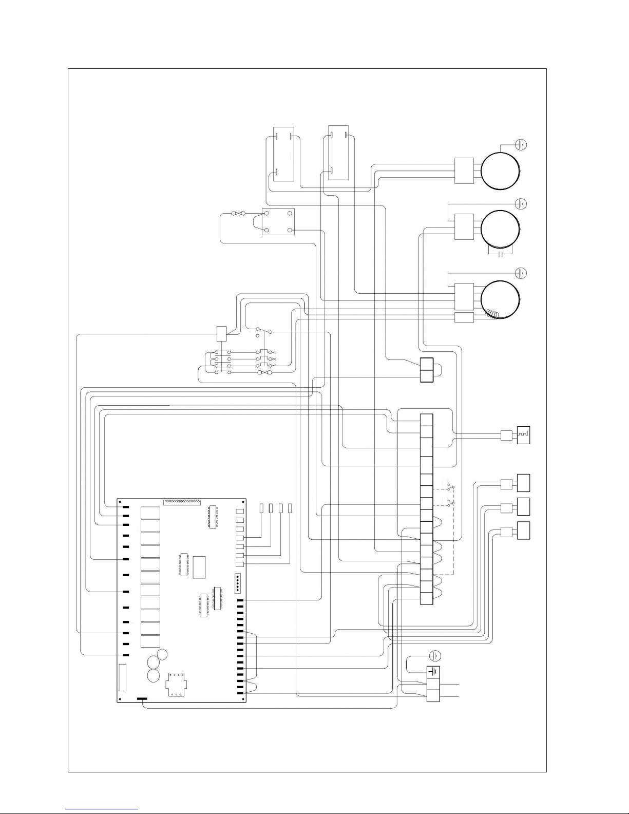
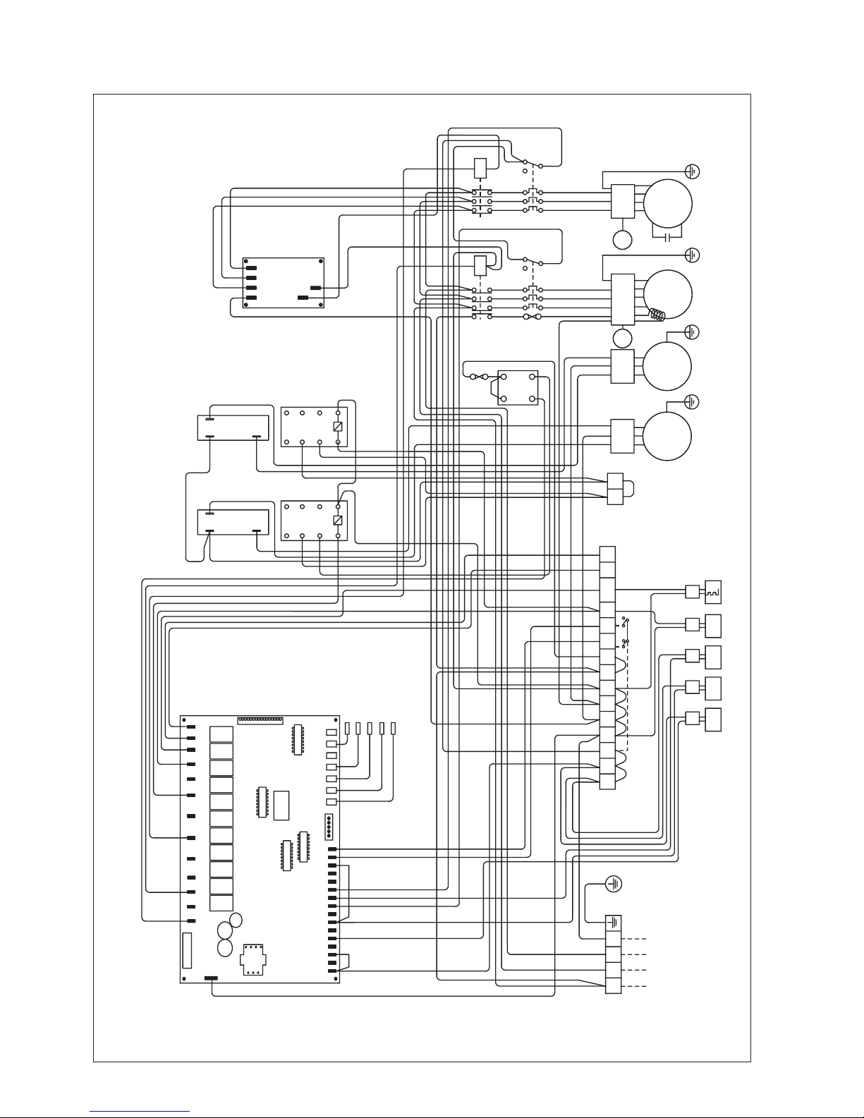
MODEL : 4AC / AC 20 C
PART NO : 50 13 4 066991
ELECTRICAL WIRING DIAGRAM
iii
Page 6
CN6
N
WI WO OA
CD1 CD2DF1 DF2
HEATOFF
COOLON
LIVE
COM2
COM1
BOILER
W_PUMP
OUT_FAN2
4WV2
A_FREEZE
ALM_OUT
ALM_IN
4WV1
OUT_FAN1
AUX-H
12V
F02
F01
LP2
LP1
HP2
HP1
C02
C01
FLOW
PO
ALM
DE2
DE1
C/H
ON/OFF
COMP DISCHARGE SENSOR (1)
OUTDOOR AIR TEMP SENSOR
LEAVING WATER SENSOR
ENTERING WATER SENSOR
N/L2
220-240/1pH/50Hz
L/L1TB1
12V 12V 12V N1 N1 N1 1 2 O/F PUMPC/H
4WV
HTR
AL
IN
AL
OUT
LP HP FL
H
T
R
OF
OUT
OF
IN
TB3
L
N
C
OF
C
S
R
E
COMP.
L
N
E
PUMP
FUSE
10A
5B
4B 1A
2A
SWITCH
A
B
COMP
COMP
CAP
98
95
96
C O/L
TB2
OF
CAP
R
R
C
S
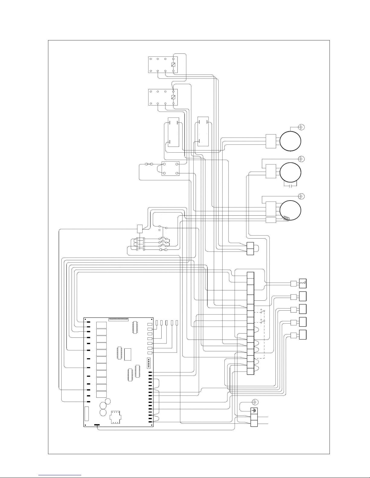
MODEL : 4AC / AC 25 / 30 C
PART NO : 50 13 4 066992
iv
Page 7

English
MODEL : 4AC / AC 40 / 50/ 60 C
PART NO : 50 13 4 076741
v
LIVE
COM2
COM1
BOILER
W_PUMP
OUT_FAN2
4WV2
A_FREEZE
ALM_OUT
ALM_IN
4WV1
OUT_FAN1
AUX-H
12V
F02
F01
LP2
LP1
HP2
HP1
CO2
CO1
FLOW
PO
ALM
DE2
DE1
C/H
ON/OFF
WI
CN6
WO OA
CD1CD2 DF1DF2
N
CA
B
OF 1
CAP
CA
B
OF 2
CAP
COMP DISCHARGE SENSOR (1)
OUTDOOR AIR TEMP SENSOR
LEAVING WATER SENSOR
ENTERING WATER SENSOR
S
380-415/3pH/50Hz
RTB1 T N
12V 12V 12V N1 N1 N1 N1 1
ON
OFF
COOL
HEAT
2 O/F C/H
4WV
HTR
AL
IN
AL
OUT
LP HP
FL
H
T
R
OF OUT
OF IN
TB3
TB2
L
N
C
OF 1
L
N
42 41
C
OF 2
U
V
W
E
COMP.
U
V
W
E
PUMP
FUSE
10A
5B
4B 1A
2A
SWITCH
31
81
71
NRST
PHASE
PROTECTOR
32
COMP PUMP
98
95
96
C O/L
98
95
96
P O/L
Page 8

MODEL : 4AC / AC 20 CR
LIVE
COM2
COM1
BOILER
W_PUMP
OUT_FAN2
4WV2
A_FREEZE
ALM_OUT
ALM_IN
4WV1
OUT_FAN1
AUX-H
12V
F02
F01
LP2
LP1
HP2
HP1
C02
C01
FLOW
PO
ALM
DE2
DE1
C/H
ON/OFF
N
CN6
WI WO OA
CD1 CD2DF1 DF2
COMP DISCHARGE SENSOR (1)
OUTDOOR AIR TEMP SENSOR
LEAVING WATER SENSOR
ENTERING WATER SENSOR
N/L2
220-240/1pH/50Hz
L/L1TB1
12V 12V 12V N1 N1 N1 1 2 O/F PUMPC/H
HEATOFF
COOLON
4WV
HTR
AL
IN
AL
OUT
LP HP FL
H
T
R
OF
OUT
OF
IN
TB3
L
N
C
OF
C
S
R
E
COMP.
L
N
E
PUMP
FUSE
10A
5B
4B 1A
2A
SWITCH
A
B
COMP
COMP
CAP
98
95
96
C O/L
1
3
2
4
DEFROST SENSOR (1)
TB2
4WV
OF
CAP
R
R
5
7
6
8
R
E
L
A
Y
1
3
2
4
5
7
6
8
R
E
L
A
Y
R1
R2
C
S
PART NO : 50 13 4 066985
vi
Page 9
English
MODEL : 4AC / AC 25 / 30 CR
PART NO : 50 13 4 066986
HEATOFF
COOLON
LIVE
COM2
COM1
BOILER
W_PUMP
OUT_FAN2
4WV2
A_FREEZE
ALM_OUT
ALM_IN
4WV1
OUT_FAN1
AUX-H
12V
F02
F01
LP2
LP1
HP2
HP1
C02
C01
FLOW
PO
ALM
DE2
DE1
C/H
ON/OFF
WI
CN6
WOOA
CD1CD2DF1DF2
N
COMP DISCHARGE SENSOR (1)
OUTDOOR AIR TEMP SENSOR
LEAVING WATER SENSOR
ENTERING WATER SENSOR
N/L2
220-240/1pH/50Hz
L/L1TB1
12V 12V 12V N1 N1 N1 1 2 O/F PUMPC/H
4WV
HTR
AL
IN
AL
OUT
LP HP FL
H
T
R
OF
OUT
OF
IN
TB3
L
N
C
OF
C
S
R
E
COMP.
L
N
E
PUMP
FUSE
10A
5B
4B 1A
2A
SWITCH
A
B
COMP
COMP
CAP
98
95
96
C O/L
1
3
2
4
DEFROST SENSOR (1)
TB2
4WV
OF
CAP
R
R
5
7
6
8
R
E
L
A
Y
1
3
2
4
5
7
6
8
R
E
L
A
Y
R1
R2
C
S
vii
Page 10
MODEL : 4AC / AC 40/ 50/ 60 CR
PART NO : 50 13 4 076742
HEATOFF
COOLON
LIVE
COM2
COM1
BOILER
W_PUMP
OUT_FAN2
4WV2
A_FREEZE
ALM_OUT
ALM_IN
4WV1
OUT_FAN1
AUX-H
12V
F02
F01
LP2
LP1
HP2
HP1
C02
C01
FLOW
PO
ALM
DE2
DE1
C/H
ON/OFF
N
C
A
B
OF 1
CAP
C
A
B
OF 2
CAP
COMP DISCHARGE SENSOR (1)
OUTDOOR AIR TEMP SENSOR
LEAVING WATER SENSOR
ENTERING WATER SENSOR
S
380-415/3pH/50Hz
RTB1 T N
12VTB2 12V 12V N1 N1 N1 N1 1 2 O/F C/H
4WV
HTR
AL
IN
AL
OUT
LP HP FL 4WV
OF OUT
OF IN
TB3
L
45 44
N
C
OF 1
L
N
C
OF 2
U
V
W
E
COMP.
U
V
W
E
PUMP
FUSE
10A
5B
4B 1A
2A
SWITCH
31
32
COMP PUMP
98
95
96
C O/L
98
95
96
P O/L
DEFROST SENSOR (1)
1R
E
L
A
Y
3
2
4
5
R1
R
E
L
A
Y
R2
7
6
8
1
3
2
4
5
7
6
8
H
T
R
CN6
WI WO OA
CD1 CD2DF1
DF2
81
71
NRST
PHASE
PROTECTOR
viii
Page 11

English
ix
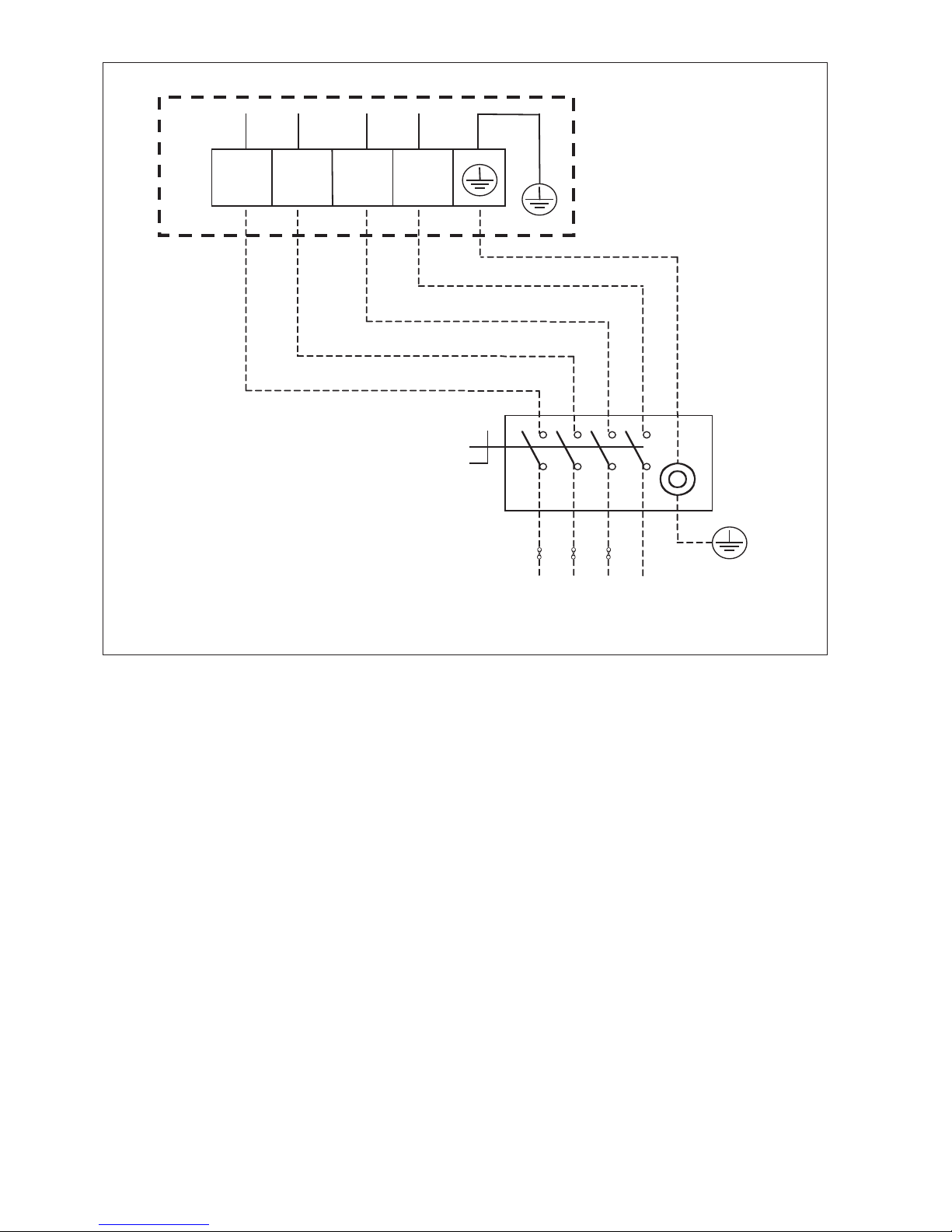
ISOLATOR DIAGRAMS
TB1 L/L1 N/L2
N
L1
Power supply 230V / 1Ph-N / 50Hz
4AC/AC20/25/30 C/CR
AC TERMINAL BOX
ISOLATOR
E
FUSE
Page 12
TB1 R S T N
NL1 L2
L3
Power supply 400V / 3Ph-N / 50Hz
4AC/AC40/50/60 C/CR
AC TERMINAL BOX
ISOLATOR
E
FUSE
x
Page 13

English
This manual provides the procedures of installation to ensure a safe and good standard of operation for the
chiller.
Special adjustments may be necessary to suit local requirements.
Before using the chiller, please read this instruction manual carefully and keep it for future reference.
INSTALLATION MANUAL
AIR COOLED CHILLER
MODEL
Part No.: A08019025453
COOLING ONLY
R22
AC20C / MAC020C
AC25C / MAC025C
AC30C / MAC030C
AC40C / MAC040C
AC50C / MAC050C
AC60C / MAC060C
R407C
4AC20C / M4AC020C
4AC25C / M4AC025C
4AC30C / M4AC030C
4AC40C / M4AC040C
4AC50C / M4AC050C
4AC60C / M4AC060C
HEAT PUMP
R22
AC20CR / MAC020CR
AC25CR / MAC025CR
AC30CR / MAC030CR
AC40CR / MAC040CR
AC50CR / MAC050CR
AC60CR / MAC060CR
R407C
4AC20CR / M4AC020CR
4AC25CR / M4AC025CR
4AC30CR / M4AC030CR
4AC40CR / M4AC040CR
4AC50CR / M4AC050CR
4AC60CR / M4AC060CR
IM-ACC1&2-0703 (1)-McQuay
!!
!!
! WARNING
• Installation and maintenance should be performed by qualified person who are familiar with local code and
regulation, and experienced with this type of appliance.
Page 14

1-1
- Recommended Fuse And Cable Sizes page 8
- Water Piping System Setup page 11
- Refrigerant Circuit page 11
-
Special Precautions When Dealing With R407C Unit
page 11
- Control Operation Guide page 12
- Servicing And Maintenance page 13
- Troubleshooting page 14
- Fan Speed Controller (Optional) page 15
- Isolator Switch Field Installation page 15
!!
!!
! CAUTION
Please take note of the following important points when installing.
• Do not install the unit where leakage of flammable gas may occur.
If gas leaks and accumulates around the unit, it may cause fire ignition.
• Do not overcharge the unit.
This unit is factory pre-charged. Overcharge will cause over-current or damage to the compressor.
• Sharp edges and aluminium fin coil surface are potential which may cause injury hazards.
Avoid from being in contact with these locations.
INDEX
- Outline And Dimensions page i-ii
- Electrical Wiring Diagram page iii-viii
- Isolator Diagram page ix-x
- Transportation page 1
- Installation Location page 2
- Unit Installation page 4
- Physical Data page 5
- Water Piping and Fitting page 7
- Electrical And Wiring page 7
- Electrical Data page 8
TRANSPORTATION
• Use spreader bars or forklift to lift the unit to avoid damage to the panels. Figure 1 provides the dimensions of the crate for
lifting. Avoid violent movements. Do not remove crate until it is at its final location.
If necessary, use crane for unit above 11kW. Check that the hanger belts are able to support the unit. Refer to the weight
of the unit given in the specification manual for assistance.
Ensure that the hanger belts are not touching the coil, top panel and front panel. Use hosting bracket (provided along with
this manual) as shown in Figure 2. Lift the unit slightly to make sure it is balance before placing it in location. Never swing
or roll the unit.
Figure 1
577
577
Page 15

1-2
English
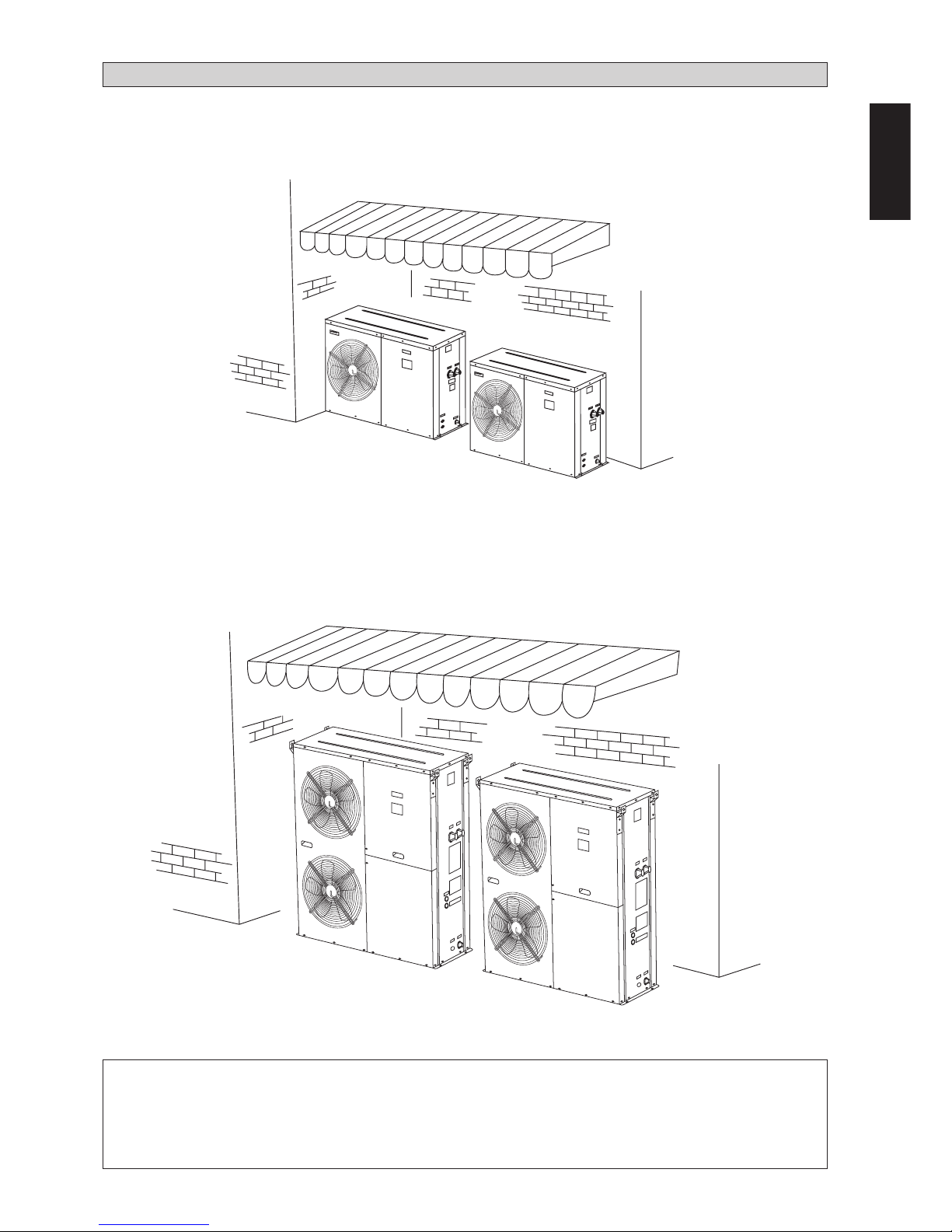
INSTALLATION LOCATION
• Installation work should be done by the authorized dealer or qualified contractor. Never install the unit yourself.
• Make sure there is sufficient space for airflow around the unit. The discharged air should be directed outside using a duct
should the unit be installed in a plant room.
• Vibration isolator should be provided to prevent vibration and noise from the unit.
• When installing the unit on the ground, make sure the selected site is not subject to flooding.
• There should be sufficient space allocated for ventilation, servicing and maintenance when installing the unit. Refer to the
following figures for proper location.
500 500
500
1500
Figure 3: For single unit installation
AIR FLOW
AIR FLOW
AIR FLOW
MIN 500
Figure 2
HANGER
HANGING BELT
Page 16

1-3
• Unit subjects to floor installation must be placed on a concrete slab. The slab must have thickness of 100mm and 50mm
wider and longer than the footprint of the unit (Figure 5). Place the concrete slab a distant from building to prevent
vibration and noise.
• In the case of heatpump operation with an outdoor temperature below 0°C, the unit must be installed at least 300mm above
ground level. This is necessary to prevent ice from accumulating on the frame and to permit proper operation in the event
of heavy snowfalls.
• The unit must be leveled on both axes. (Tolerance is less than 2mm per meter.)
Figure 5: For floor installation
Note: All units are in mm unless specified.
500
1000
1000 500
1500
Figure 4: For multiple unit installation
AIR FLOW
AIR FLOW
AIR FLOW
AIR FLOW
AIR FLOW
AIR FLOW
AIR FLOW
MIN 500
50 50
100
Page 17
1-4
English
4AC/AC 020/025/030 C/CR
UNIT INSTALLATION
!!
!!
! CAUTION
• Improper handling of unit during installation could result in leaks, electrical shock or unit malfunction.
• Contact your dealer for reinstallation or dismantling of unit.
• Do not introduce foreign objects such as fingers, sticks etc. into the air inlet and air outlet.
• Do not climb or place objects on top of mini chiller.
4AC/AC 040/050/060 C/CR
Page 18

1-5
PHYSICAL DATA
Note: For cooling nominal values are based on 12°C / 7°C entering / leaving evaporator water temperature, 35°C air ambient temperature.
Table A-1 : R407C - Cooling Only
Model 4AC20C 4AC25C 4AC30C 4AC40C 4AC50C 4AC60C
Nominal cooling capacity kW 6.15 6.74 7.91 11.72 14.65 15.24
Operating Weight kg 115.5 122.5 128 195 196.4 203.2
Refrigerant charge R407C kg 1.13 1.85 1.65 3.40 3.35 3.45
Compressor 1 Rotary comp 1 Scroll compressor
Control system LCD Electronic Control
Refrigerant - water heat exchanger Brazed Plate Heat Exchanger
Water connections (BSP) inches 111111
Maximum water pressure kPa 1000 1000 1000 1000 1000 1000
Hydronic circuit
Pump High Head Circulator Horizontal Multistage End-Suction
Available pressure kPa 72.94 98.58 89.27 91.70 67.51 70.32
Water inlet connection (BSPT) inches 111111
Water outlet connection (BSPT) inches 111111
Drain tap coupling (BSPT) inches 1/2 1/2 1/2 1/2 1/2 1/2
Closed expansion tank water volume litre 222555
Refrigerant - air heat exchanger
Tube diameter mm 9.52 9.52 9.52 9.52 9.52 9.52
No. of rows 122222
Tubes/row 30 30 30 54 54 54
Fin spacing mm
1.27 1.59 1.59 1.59 1.59 1.59
O/D Fan
Diameter inches 18 18 18 18/2 18/2 18/2
No. of blades 555555
Air flow (high speed) m3/min 62.3 62.3 62.3 62.3 62.3 62.3
Fan speed (high speed) r/min 910 920 920 920 920 920
Table A-2 : R22 - Cooling Only
Model AC20C AC25C AC30C AC40C AC50C AC60C
Nominal cooling capacity kW 5.28 6.89 8.06 11.72 14.65 15.53
Operating Weight kg 115.5 122.5 128 195 196.4 203.2
Refrigerant charge R22 kg 1.13 1.80 1.56 2.68 3.10 3.10
Compressor 1 Rotary comp 1 Scroll compressor
Control system LCD Electronic Control
Refrigerant - water heat exchanger Brazed Plate Heat Exchanger
Water connections (BSP) inches 111111
Maximum water pressure kPa 1000 1000 1000 1000 1000 1000
Hydronic circuit
Pump High Head Circulator Horizontal Multistage End-Suction
Available pressure kPa 83.55 97.39 88.08 91.70 67.51 65.98
Water inlet connection (BSPT) inches 111111
Water outlet connection (BSPT) inches 111111
Drain tap coupling (BSPT) inches 1/2 1/2 1/2 1/2 1/2 1/2
Closed expansion tank water volume litre 222555
Refrigerant - air heat exchanger
Tube diameter mm 9.52 9.52 9.52 9.52 9.52 9.52
No. of rows 122222
Tubes/row 30 30 30 54 54 54
Fin spacing mm
1.27 1.59 1.59 1.59 1.59 1.59
O/D Fan
Diameter inches 18 18 18 18/2 18/2 18/2
No. of blades 555555
Air flow (high speed) m
3
/min 62.3 62.3 62.3 62.3 62.3 62.3
Fan speed (high speed) r/min 910 920 920 920 920 920
Page 19

1-6
English
Note: For cooling nominal values are based on 12°C / 7°C entering / leaving evaporator water temperature, 35°C air ambient temperature.
For heating nominal values are based on 40°C / 45°C entering / leaving evaporator water temperature, 7°C/6°C (DB/WB) air ambient temperature.
Table A-3 : R407C - Heatpump
Model 4AC20CR 4AC25CR 4AC30CR 4AC40CR 4AC50CR 4AC60CR
Nominal cooling capacity kW 4.98 6.45 7.33 11.72 13.48 14.95
Nominal heating capacity kW 5.86 7.47 9.53 13.19 14.95 17.58
Operating Weight kg 115.5 122.5 128.0 195.0 196.4 203.2
Refrigerant charge R407C kg 1.50 1.75 1.60 3.00 3.45 4.00
Compressor 1 Rotary comp 1 Scroll compressor
Control system LCD Electronic Control
Refrigerant - water heat exchanger Brazed Plate Heat Exchanger
Water connections (BSP) inches 111111
Maximum water pressure kPa 1000 1000 1000 1000 1000 1000
Hydronic circuit
Pump High Head Circulator Horizontal Multistage End-Suction
Available pressure (Cooling / Heating) kPa 87.21/76.47 100.89/92.77 93.89/76.38 91.70/74.54 82.15/63.75 74.67/35.27
Water inlet connection (BSPT) inches 111111
Water outlet connection (BSPT) inches 111111
Drain tap coupling (BSPT) inches 1/2 1/2 1/2 1/2 1/2 1/2
Closed expansion tank water volume litre 222555
Refrigerant - air heat exchanger
Tube diameter mm 9.52 9.52 9.52 9.52 9.52 9.52
No. of rows 122222
Tubes/row 30 30 30 54 54 54
Fin spacing mm
1.27 1.59 1.59 1.59 1.59 1.59
O/D Fan
Diameter inches 18 18 18 18/2 18/2 18/2
No. of blades 555555
Air flow (high speed) m
3
/min 62.3 62.3 62.3 62.3 62.3 62.3
Fan speed (high speed) r/min 910 920 920 920 920 920
Table A-4 : R22 - Heatpump
Model AC20CR AC25CR AC30CR AC40CR AC50CR AC60CR
Nominal cooling capacity kW 5.28 6.74 8.06 11.72 13.48 15.53
Nominal heating capacity kW 6.45 7.33 9.23 12.60 15.24 17.29
Operating Weight kg 115.5 122.5 128.0 195.0 196.4 203.2
Refrigerant charge R22 kg 1.55 1.93 1.75 3.00 3.65 4.00
Compressor 1 Rotary comp 1 Scroll compressor
Control system LCD Electronic Control
Refrigerant - water heat exchanger Brazed Plate Heat Exchanger
Water connections (BSP) inches 111111
Maximum water pressure kPa 1000 1000 1000 1000 1000 1000
Hydronic circuit
Pump High Head Circulator Horizontal Multistage End-Suction
Available pressure (Cooling / Heating) kPa 83.55/69.27 98.58/93.89 88.08/78.76 91.70/81.42 82.15/60.12 65.98/39.62
Water inlet connection (BSPT) inches 111111
Water outlet connection (BSPT) inches 111111
Drain tap coupling (BSPT) inches 1/2 1/2 1/2 1/2 1/2 1/2
Closed expansion tank water volume litre 222555
Refrigerant - air heat exchanger
Tube diameter mm 9.52 9.52 9.52 9.52 9.52 9.52
No. of rows 122222
Tubes/row 30 30 30 54 54 54
Fin spacing mm
1.27 1.59 1.59 1.59 1.59 1.59
O/D Fan
Diameter inches 18 18 18 18/2 18/2 18/2
No. of blades 555555
Air flow (high speed) m3/min 62.3 62.3 62.3 62.3 62.3 62.3
Fan speed (high speed) r/min 910 920 920 920 920 920
Page 20
1-7
WATER PIPING AND FITTING
• All water pipe must be adequately insulated to prevent capacity losses and condensation.
• Install a 40 to 60-mesh strainer to ensure good water quality.
• Water pipes recommended are black steel pipe and copper pipe.
• During installation, the piping of the unit should be clamped before rotating the installation pipe to reduce the moment
induce on the piping.
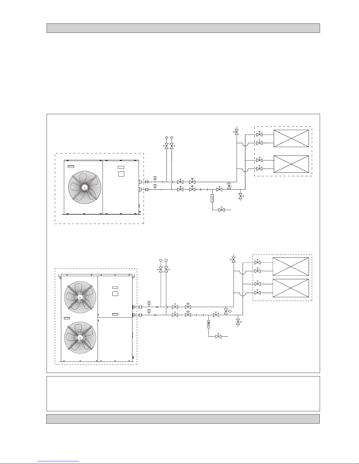
• Users are recommended to install the pipes and accessories as shown in Figure 6.
• An air vent must be installed at the highest position, while a drainage plug at the lowest position of the water circuit. After
the leak test (0.6MPa), open the air vent to release any air trapped in the water circuit.
• Run the clean water through the water inlet and operate the pump to drain out the dirty water. Clean the strainer after
running the pump for 30 minutes.
• Fill up the water circuit after connecting the pipes and equipment. Check water leakage at all connections and joints. Do
not start the unit when the system is leaking.
• To optimize the capacity of the system, ensure that the system is free of air bubbles. The air trapped in the system would
make the system unbalanced.
!!
!!
! CAUTION
• Do not allow water to remain in the water pipes if the unit is not operating for a long period.
Water must be drained out if the unit is not running during winter. Failing to do so would cause the pipe to crack.
• Do not drink the chilled water in the unit.
P
P
4AC/AC 20/25/30 C/CR
4AC/AC 40/50/60 C/CR
PRESSURE GAUGE
GATE
VALVE
GATE
VALVE
BALANCING
VALV E
THERMOMETER
FLEXIBLE
GATE VALVE (LOWER
POSITION FOR DRAINAGE)
AIRVENT (INSTALL
HIGHEST POSITION)
FAN COIL UNIT/AIR HANDLING UNIT
GATE
VALV E
Figure 6
THERMOMETER
GATE VALVE
GATE VALVE
BALANCING
VALV E
STRAINER
CHECK
VALVE
MAKE UP
VALV E
BYPASS VALVE
(DIFFER ENT PRESSURE TYPE)
PRESSURE GAUGE
GATE
VALVE
GATE
VALVE
BALANCING
VALV E
THERMOMETER
FLEXIBLE
GATE VALVE (LOWER
POSITION FOR DRAINAGE)
AIRVENT (INSTALL
HIGHEST POSITION)
FAN COIL UNIT/AIR HANDLING UNIT
GATE
VALVE
THERMOMETER
GATE VALVE
GATE VALVE
BALANCING
VALV E
STRAINER
CHECK
VALV E
MAKE UP
VALV E
BYPASS VALVE
(DIFFER ENT PRESSURE TYPE)
ELECTRICAL AND WIRING
• Refer to the wiring diagram provided on the unit when making electrical wiring.
• Do not ground any electrical equipment to the water piping.
• Install an external isolator switch (if it is not provided) to prevent electrical shock.
Page 21
1-8
English
4AC20C/CR 4AC25C/CR 4AC30C/CR 4AC40C/CR 4AC50C/CR 4AC60C/CR
Model
AC20C/CR AC25C/CR AC30C/CR AC40C/CR AC50C/CR AC60C/CR
Voltage Range ** 220 ~ 240V /1Ph /50Hz + N + ! 380 ~ 415V /3Ph /50Hz + N + !
Recommended Fuse * A 27 38 45 22 24 29
Power Supply Cable Size * mm
2
10 10 10 5 5 5
Number of Conductor 3 3 3 5 5 5
Interconnection Cable Size * mm
2
1.5 1.5 1.5 1.5 1.5 1.5
ELECTRICAL DATA
Table B-1 : ( R407C - Cooling Only )
Model 4AC20C 4AC25C 4AC30C 4AC40C 4AC50C 4AC60C
Power supply V-ph-Hz 230 / 1 / 50 400 / 3 / 50
Voltage range V 220 - 240 380 - 415
Nominal Power Input kW 2.62 2.96 3.69 4.94 5.97 6.88
Nominal Current Input A 12.70 13.59 17.48 9.29 10.22 12.93
Maximum Continuous Current A 18.3 23 27 14 14 17
Full Load Current (FLA) A 14 17.5 22.5 12.4 11.8 14.3
Locked Rotor Current (LRA) A 57 82 114 65.5 74 101
Pump Power Input W 183 189 199 320 345 349
Cooling / Heat Pump
RECOMMENDED FUSE AND CABLE SIZES
IMPORTANT : *
The figures shown in the table are for information purpose only. They should be checked and selected to comply with
the local/national codes of regulations. This is also subjected to the type of installation and conductors used.
**
The appropriate voltage range should be checked with label data on the unit.
!!
!!
! CAUTION
• All field wiring must be installed in accordance with the national wiring regulation.
• All the terminals and connections must be tightened. Improper connection and fastenings could cause electric shock, short
circuit and fire.
• Ensure that the rated voltage of the unit corresponds to that of the name plate before commencing wiring work according to
the wiring diagram.
• The unit must be GROUNDED to prevent possible hazards due to insulation failure.
• All electrical wiring must not touch the refrigerant piping, compressor, pump, fan motor or any moving parts of the fan
motors.
• Do not operate the chiller with wet hands. It would result in electric shock.
• Do not use fuse of different amperage than stated. Using wire etc. to replace a fuse could cause equipment damage or fire.
Table B-2 : ( R22 - Cooling Only )
Model AC20C AC25C AC30C AC40C AC50C AC60C
Power supply V-ph-Hz 230 / 1 / 50 400 / 3 / 50
Voltage range V 220 - 240 380 - 415
Nominal Power Input kW 2.68 2.74 3.50 4.50 5.26 6.38
Nominal Current Input A 12.64 12.11 16.70 8.80 9.30 12.32
Maximum Continuous Current A 18.3 23 27 14 14 17
Full Load Current (FLA) A 14 16.5 21.4 10.5 11.3 12.3
Locked Rotor Current (LRA) A 57 82 114 65.5 74 101
Pump Power Input W 175 190 201 320 345 351
Table B-3 : ( R407C - Heatpump )
Model 4AC20CR 4AC25CR 4AC30CR 4AC40CR 4AC50CR 4AC60CR
Power supply V-ph-Hz 230 / 1 / 50 400 / 3 / 50
Voltage range V 220 - 240 380 - 415
Nominal Power Input (Cooling/Heating) kW 2.61/2.69 3.09/2.75 3.82/4.00 4.85/5.01 5.47/5.66 6.53/6.28
Nominal Current Input (Cooling/Heating)
A 12.69/12.99 14.3/14.1 19.29/20.19 9.13/9.23 9.59/9.96 12.77/12.67
Maximum Continuous Current A 18.3 23 27 14 14 17
Full Load Current (FLA) A 14 17.5 22.5 12.4 11.8 14.3
Locked Rotor Current (LRA) A 57 82 114 65.5 74 101
Pump Power Input (Cooling/Heating) W 173/181 186/195 194/214 320/334 336/347 347/358
Table B-4 : ( R22 - Heatpump )
Model AC20CR AC25CR AC30CR AC40CR AC50CR AC60CR
Power supply V-ph-Hz 230 / 1 / 50 400 / 3 / 50
Voltage range V 220 - 240 380 - 415
Nominal Power Input (Cooling/Heating) kW 2.61/2.70 2.95/2.83 3.55/3.56 4.59/4.65 5.07/5.01 6.57/6.26
Nominal Current Input (Cooling/Heating)
A 12.38/12.73 13.4/12.8 18.24/18.37 8.67/8.78 8.99/8.95 13.49/13.03
Maximum Continuous Current A 18.3 23 27 14 14 17
Full Load Current (FLA) A 14 16.5 21.4 10.5 11.3 12.3
Locked Rotor Current (LRA) A 57 82 114 65.5 74 101
Pump Power Input (Cooling / Heating) W 175/186 189/194 201/211 320/329 336/349 351/357
Page 22

1-9
P
P
4AC / AC 20C/ 25C/ 30C
Water / Refrigerant Circuit Diagram
FILTER
DRIER
CAP TUBE
BPHE
COMPRESSOR
WATER PUMP
AUTO PRESS RELIEF VALVE
WATER
OUT
WATER
IN
EXPANSION
TANK
WATER STORAGE
TANK
4AC / AC 40C/ 50C/ 60C
Water / Refrigerant Circuit Diagram
FILTER
DRIER
CAP TUBE
BPHE
COMPRESSOR
WATER PUMP
AUTO PRESS RELIEF VALVE
WATER
OUT
WATER
IN
EXPANSION
TANK
WATER STORAGE
TANK
PART NO : 70-03-4-067460
PART NO : 70-03-4-087461
Page 23

1-10
English
P
P
4AC / AC 20CR/ 25CR/ 30CR
Water / Refrigerant Circuit Diagram
CHECK
VALV E
BPHE
COMPRESSOR
CHARGE
COMPENSATOR
AUTO PRESS RELIEF VALVE
WATER
OUT
WATER
IN
EXPANSION
TANK
WATER STORAGE
TANK
PART NO : 70-03-4-067458
4AC / AC 40CR/ 50CR/ 60CR
Water / Refrigerant Circuit Diagram
BPHE
COMPRESSOR
WATER PUMP
AUTO PRESS RELIEF VALVE
WATER
OUT
WATER
IN
EXPANSION
TANK
WATER STORAGE
TANK
PART NO : 70-03-4-067459
CHECK
VALV E
FILTER
DRIER
HEATING
CAP
TUBE
COOLING
CAP
TUBE
SUCTION
ACCUMULATOR
CHECK
VALV E
LIQUID
RECEIVER
CHECK
VALV E
FILTER
DRIER
HEATING
CAP
TUBE
COOLING
CAP
TUBE
SUCTION
ACCUMULATOR
Page 24

1-11
REFRIGERANT CIRCUIT
• All mini chiller units are pre-charged with R22 or R407C refrigerant.
SPECIAL PRECAUTIONS WHEN DEALING WITH R407C UNIT
• R407C is a zeotropic refrigerant mixture which has zero ozone depletion potential and thus conformed to the Montreal
Protocol regulation. It requires Polyester oil (POE) oil for its compressor lubricant. Its refrigerant capacity and performance are about the same as the refrigerant R22.
• POE oil is used as lubricant for R407C compressor, which is different from the mineral oil used for R22 compressor.
During installation or servicing, extra precaution must be taken not to expose the R407C system too long to moist air.
Residual POE oil in the piping and components can absorb moisture from the air.
• Refrigerant R407C is more easily affected by dust of moisture compared with R22, make sure to temporarily cover the
ends of the tubing prior to installation.
• No additonal charge of compressor oil is permitted.
• No other refrigerant other than R407C.
• Tools specifically for R407C only (must not be used for R22 or other refrigerant)
i) Manifold gauge and charging hose
ii) Gas leak detector
iii) Refrigerant cylinder/charging cylinder
iv) Vacuum pump c/w adaptor
v) Flare tools
vi) Refrigerant recovery machine
!!
!!
! CAUTION
• R407C must be charged as liquid. Usually R407C cylinder is equipped with a dip-pipe for liquid withdrawal.
If there is no dip-pipe, the cylinder should be inverted so as to withdraw liquid R407C from the valve.
• Do not top-up when servicing leak, as this will reduce the unit performance. Vacuum the unit thoroughly and then
charge the unit with fresh R407C according to the amount recommended in the specification.
• Do not touch the compressor or refrigerant piping when the chiller is running. If necessary wear protective gloves.
WATER PIPING SYSTEM SETUP
• Fill up the water circuit after connecting all the pipes and equipment. Perform leak checks for all connections and joints.
Do not start the unit when the system is leaking.
• To optimize the capacity of the system, ensure that the system is free of air bubbles. The air trapped in the system would
make the system unbalanced.
• Ensure that the water tank is not full. This is to ensure optimal performance of the mini chiller. If the pressure is too high,
release the pressure from the auto pressure relief valve on the tank.
Page 25
1-12
English
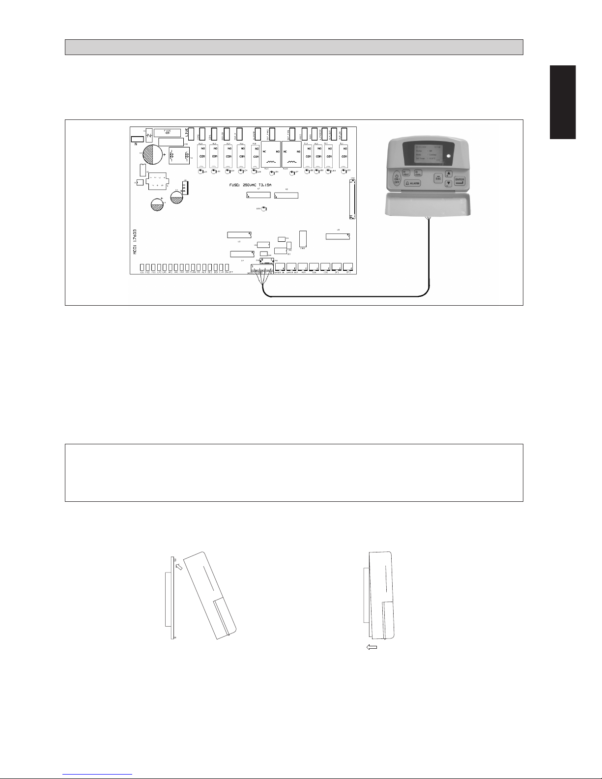
1. Handset location
The handset is located in the terminal box behind the service panel.
2. LED Display (microprocessor board)
The keypad LED will light up when the unit is powered up.
The LCD will light up when the unit is turned on.
3. LCD display (controller handset)
During normal operations, the LCD can display the entering water temperature, the leaving water temperature, the entering water setpoint temperature, compressor on or off status and outdoor air temperature. When malfunctioning occurred,
the LCD would blink. The display would show the faulty parameter and the date and time of the occurrence.
4. Controller functioning specification
There is a 3 minute delay for the compressor and fan motor to restart (default setting).
CONTROL OPERATION GUIDE
The unit is equipped with a microprocessor controller board. The microprocessor controller is provided to give temperature
control for the system by accurately measuring and controlling the water entering and water leaving temperature. The temperature setting in the unit is preset in the factory. It is not recommended to change the setting unless necessary. A wired
controller handset is connected to the microprocessor board. Every parameter setting and reading can be observed from the
LCD of the handset.
!!
!!
! CAUTION
• Use the controller handset to switch on / off the unit. Do not plug off the main power supply directly, it would cause
the unit to breakdown.
• Do not change the settings of the safety devices.
• Installation
When fastening the LCD panel to the bracket,
Step 1 Step 2
Hook the LCD panel
from the top first
Push to fasten the LCD
panel to the bracket
Page 26

1-13
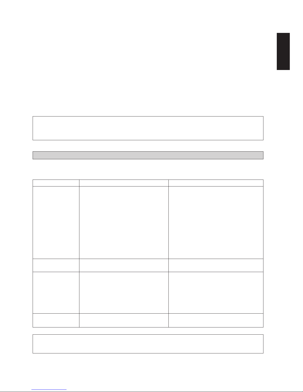
• Servicing
Servicing or maintenance of these units must be carried out by experienced personnel with specific training in refrigeration.
Repeatedly check the safety devices and continuous cycling of control components. These items must be analyzed and
corrected before being reset.
The simple design of the refrigeration circuit totally eliminates potential problems during normal unit operation. No maintenance work is needed on the refrigeration circuit as long as the unit is operating normally.
Ease of maintenance has been taken into consideration during the design stage such that the unit is easily accessible from the
service panels. The electrical components are especially easy to access since it is located in the terminal box in the front
service panel (Figure 7).
SERVICING AND MAINTENANCE
Figure 7
1. A 3V DC battery is supplied with the LCD. It is used to ensure that the LCD displays real time once the timer is set.
2. The LCD is wired to the main board via CN8 connection. (This is factory installed)
If the wiring between the LCD and PCB must be longer, an alternative is used. Use a 4-core wire of the desired length and
connect this wire between the terminal block CN2 on the LCD to the terminal block CN5 on the PCB. Ensure that the
correct wire terminals are connected.
3. Networking between chillers can be carried out. Connect the wire as shown
When removing the LCD panel from the bracket,
Step 1 Step 2
Remove the LCD panel
from the bottom part first
with help of a screw driver
Remove the
LCD panel
Factory installed
Alternative wiring between LCD panel and PCB
For networking only
A
A
A
B
B
B
12V
12V
12V
GND
GND
GND
JP13
CN8
CN2
CN5
Main Board Unit 00
LCD Panel
PCB Unit 01
Page 27
1-14
English
1. Compressor does
not start.
2. Fan does not work.
3. Unit does work,
but insufficient
cooling.
4. Flow Switch Error
TROUBLESHOOTING
When any malfunction is occurred, immediately switch off the power supply to the unit, and contact the local dealer, if
necessary. Some simple troubleshooting tips are given below :
SYMPTOMS POSSIBLE CAUSES REMEDIAL ACTION
• No power supply.
• Fuses blown or automatic circuit breakdown open.
• Defective contactor or coil.
• Unit is stopped because safety device has
tripped.
• Loose wires.
• Compressor faulty.
• No power supply.
• Fan motor faulty.
• Thermostat setting too high.
• Condenser coil dirty.
• Obstacle blocking air inlet or outlet of the
unit.
• Insufficient refrigerant in the system.
• Improper water flow rate.
• Water in the system is contaminated.
• No water in the system.
• Low water level in the system.
• Check power supply.
• Look for short circuit or grounded wires in
motor windings. Replace fuses and reset
circuit breakers when the fault has been
corrected. Check tightness and soundness of
all electrical connections.
• Repair or replace.
• Determine the type of safety shut down and
correct the default before the unit is restarted.
• Check wire connections and tighten terminal
screws.
• Contact local dealer.
• Check power supply.
• Contact local dealer.
• Reset thermostat.
• Contact local dealer.
• Remove the obstacle.
• Contact local dealer.
• Contact local dealer.
• Contact local dealer.
• Check water supply.
• Check water supply.
!!
!!
! CAUTION
• Troubleshooting must be performed by qualified personnel.
!!
!!
! CAUTION
• Do not attempt to do any service or maintenance when the unit is operating.
• Do not spray any chemical agents or flammable agents to the unit. It could cause fire or explosion.
Under normal circumstances, these chillers required only a check and cleaning of air intake through the coil surface. These
can be done monthly or quarterly depending on the surrounding where the units are installed.
When the surrounding is very oily or dusty, then the coils must be regularly cleaned by a qualified air condition service
technician to ensure sufficient cooling capacity and efficient unit operation. The normal life span might be shortened if no
proper service is provided.
• Maintenance
For consistent performance and durability, always conduct proper and regular maintenance to the unit.
For prolong period of operation time, the heat exchanger will become dirty impairing its effectiveness and reducing the
performance of the units. Consult your local dealer about the cleaning of the heat exchanger.
No major maintenance or servicing is needed for the internal water circuit in the unit except the water pump failure. It is
advisable to conduct regular check on the filter and change the water filter if it is dirty or choked.
Always check the water level in the system in order to protect the moving components in the hydraulic kit from over heating
and excessive wear.
Page 28
1-15
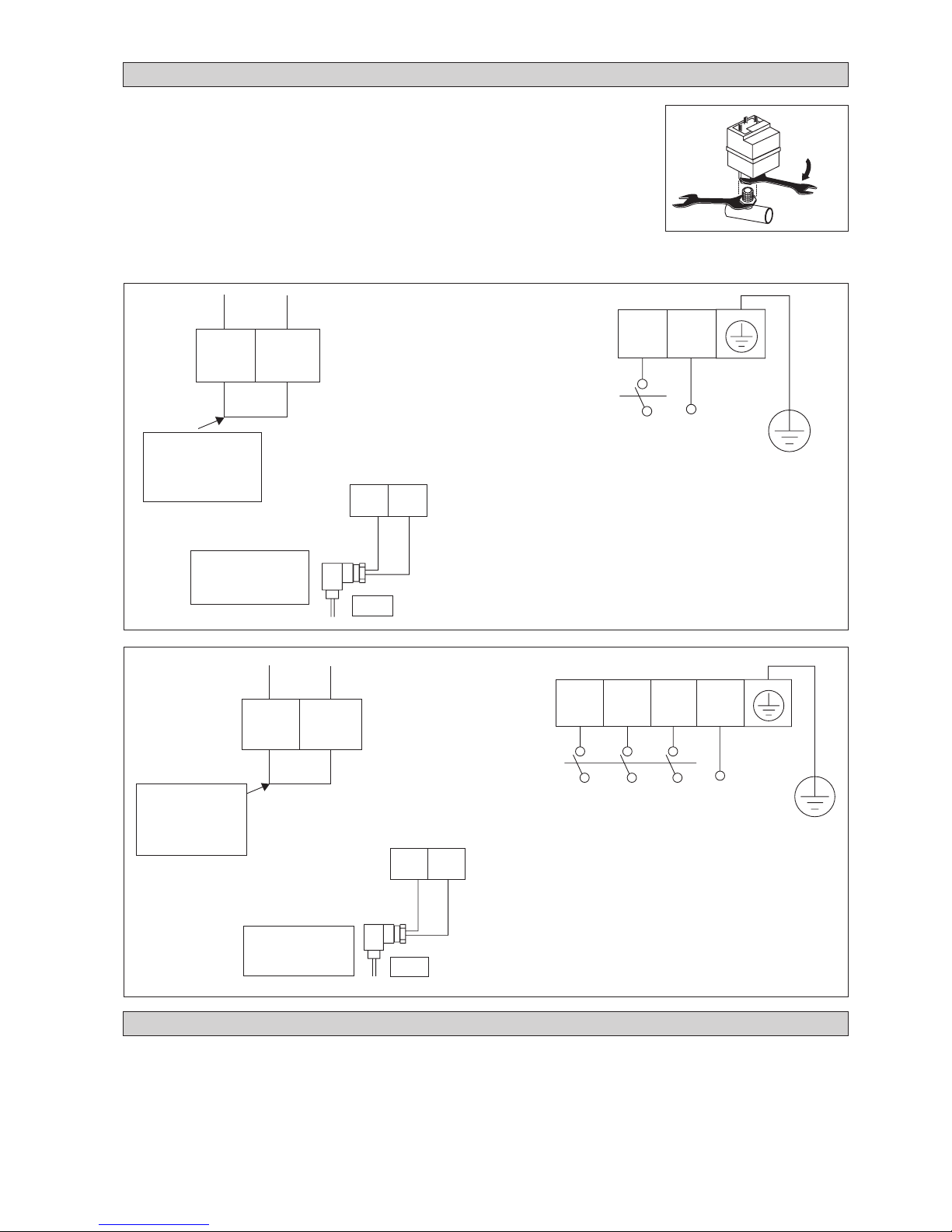
Figure 9
4AC/AC40/50/60 C/CR
Remove this wire
when doing
wiring for fan
speed controller
Wiring for fan
speed controller
(FSC)
FSC
OF IN
OF OUT
TB3
TB3
OF IN OF OUT
TO (PCB)
OUT_FAN1
TO (A) OF_1
CAPACITOR
Power supply 400V / 3Ph-N / 50Hz
L1 N
TB1
R
S
TN
L2
L3
ISOLATOR SWITCH FIELD INSTALLATION
The isolator switch does not come as standard item with the units. It is advisable to have it field installed. The isolator switch must
be capable of making, carrying and breaking currents under normal circuit condition. It must be of AC23A duty and fully compliant
to IEC: 947-3.
For isolator switch selection, check the starting and running consumption specified in Table B. Be sure to connect a ground wire
from incoming power supply, either direct to the terminal box panel or use an auxiliary ground terminal in the isolator switch. To
install an isolator switch, wire it to the terminal block as shown in the two figures in page ix.
Operation of the mini chillers without any fan speed control is limited to an ambient temperature
of 17°C. With the fan speed control, the units are able to operate down to -5°C.
The fan speed controller does not come as a standard item in the mini chiller units. It is fieldinstalled.
All mini chillers will have a 1/4" access valve provided for along the liquid line of the refrigerant
circuit. This valve is for direct pressure connection to the fan speed controller.
To install the fan speed controller, screw in the female adaptor to the 1/4" access valve. Use a
pair of spanners to tighten properly (max. torque 15 Nm). See Fig. 8. Ensure there is no leakage
at the joint.
Wire the fan speed controller to the terminal blocks. See Fig. 9.
FAN SPEED CONTROLLER (OPTIONAL)
TB3
Power supply 230V / 1Ph-N / 50Hz
Remove this wire
when doing wiring
for fan speed
controller
Figure 8
OF IN OF OUT
OF IN
OF OUT
Wiring for fan
speed controller
(FSC)
FSC
TB3
TO (PCB)
OUT_FAN1
TO (A) OF
CAPACITOR
L1 N
TB1
L/L1 N/L2
4AC/AC20/25/30 C/CR
15 Nm
Page 29

English
Le présent manuel fournit les procédures d’installation pour assurer le bon fonctionnement et la sécurité du
refroidisseur.
Des ajustements spésifiques peuvent être nécessaires pour se conformer aux réglementations locales.
Avant d’employer le refroidisseur, lisez attentivement ce manuel, et conservez-le pour consultation future.
MANUEL D’INSTALLATION
REFROIDISSEUR À AIR
MODÈLE
FROID SEUL
R22
AC20C / MAC020C
AC25C / MAC025C
AC30C / MAC030C
AC40C / MAC040C
AC50C / MAC050C
AC60C / MAC060C
R407C
4AC20C / M4AC020C
4AC25C / M4AC025C
4AC30C / M4AC030C
4AC40C / M4AC040C
4AC50C / M4AC050C
4AC60C / M4AC060C
POMPE À CHALEUR
R22
AC20CR / MAC020CR
AC25CR / MAC025CR
AC30CR / MAC030CR
AC40CR / MAC040CR
AC50CR / MAC050CR
AC60CR / MAC060CR
R407C
4AC20CR / M4AC020CR
4AC25CR / M4AC025CR
4AC30CR / M4AC030CR
4AC40CR / M4AC040CR
4AC50CR / M4AC050CR
4AC60CR / M4AC060CR
!!
!!
! ATTENTION
• L’installation et la maintenance doivent être exécutées par une personne qualifiée qui est familiarisée avec les lois
et réglementations en vigueur, et aussi expérimentée dans ce type d’équipements.
Part No.: A08019025453
IM-ACC1&2-0703 (1)-McQuay
Page 30

2-1
- Sections Des Cables Et Fusibles De Protection page 8
- Montage des Conduites d’Eau page 11
- Circuit Frigori Fique page 11
- Précautions Spéciales Pour les Appareils Au R407C page 11
- Unité de Contrôle des Opérations page 12
- Entretien et Maintenance page 13
- Recherche Et Anlyse Des Pannes page 14
- Contrôle de la Vitesse du Ventilateur (en Option) page 15
-
Installation sur Place d’un Interrupteur d’Isolement
page 15
!!
!!
! AVERTISSEMENT
Lors de l’installation, vérifier soigneusement les points suivants.
• Ne pas installer dans des endroits où il y a risque de fuites de gaz.
Danger d’incendie en cas de fuite ou de concentration de gaz à proximité du conditionneur.
• Ne pas surcharger le conditionneur.
L’appareil est pré-chargé en usine. Toute surcharge provoquerait une surintensité et des dommages au
compresseur.
• Les angles pointus et la surface des ailettes en aluminium du condenseur peuvent être
dangeureux et provoquer des accidents. Evitez tout contact avec ce type d’endroits.
SOMMAIRE
- Disposition et Dimensions page i-ii
- Schéma de Câblage Électrique page iii-viii
- Schéma de Sectionnement page ix-x
- Transport page 1
- Sélection de l’Emplacement page 2
- Installation de l’unité page 4
- Données Physiques page 5
- Circuit Hydraulique page 7
- Equipement Electrique et Câblage page 7
- Données Électriques page 8
TRANSPORT
• Soulever l’unité avec un palonnier ou un chariot à fourche pour éviter d’endommager les panneaux. La figure 1 indique les
dimensions de la pallette pour le levage. Éviter les mouvements brusques. Ne pas retirer la pallette avant d’atteindre
l’emplacement final.
Au besoin, utiliser une grue pour soulever une unité de plus de 11kW. Vérifier que les élingues sont assez fortes pour
soutenir l’unité. Consulter le manuel technique pour en connaître le poids.
S’assurer que les élingues ne touchent ni la batterie du condenseur, ni le panneau supérieur, ni le panneau avant. Utiliser
une ferrure de levage (fournie avec le présent manuel) comme indiqué dans la figure 2. Soulever légèrement l’unité pour
vérifier qu’elle est en équilibre avant de la mettre en place. Ne jamais balancer ou rouler l’unité.
Figure 1
577
550
Page 31

2-2
Français
SÉLECTION DE L’EMPLACEMENT
• L’installation doit être effectvée par un distributeur autorisé ou par du personnel qualifié. Ne jamais installer l’unité soimême.
• S’assurer de la présence d’un flux d;air suffisant autour de l’appareil. L’air refoulé doit être acheminé dehors à l’aide d’un
conduit si l’unité est installée dans un local d’usine.
• Un dispositif d’isolation doit être fourni pour réduire les vibrations et le bruit de l’appareil.
• Lors d’une installation au sol de l’unité, s’assurer que l’emplacement choisi n’est pas à risque d’inondation.
• Lors de l’installation, prévoir un espace libre pour la ventilation, l’entretien et la maintenance de l’unité. Voir les figures
suivantes pour une mise en place correcte.
500 500
500
1500
Figure 3: Pour l’installation d’une seule unité
FLUX D’AIR
FLUX D’AIR
FLUX D’AIR
MIN 500
Figure 2
CROCHET
ELINGUE
Page 32

2-3
• L’unité installée au sol doit être déposée sur une dalle de béton. La dalle doit avoir une épaisseur de 100mm et dépasser de
50mm le pourtour de l’unité (Figure 5). Placer la dalle de béton à distance de l’édifice pour prévenir les vibrations et le
bruit.
• En cas d’emploi d’une thermopompe à une température extérieure sous 0°C, l’unité doit être installée au moins 300mm audessus du sol. C’est nécessaire pour empêcher la glace de s’accumuler sur le cadre et pour permettre un fonctionnement
adéquat lors de chutes de neige abondantes.
• L’unité doit être à niveau sur ses deux axes. (Tolérance inférieure à 2mm par mètre.)
50 50
100
Figure 5: Pour l’installation sur plancher
Remarque: Toutes les mesures sont en mm à moins d’indication contraire.
500
1000
1000 500
1500
Figure 4: Pour l’installation de multiples unités
FLUX D’AIR
FLUX D’AIR
FLUX D’AIR
FLUX D’AIR
FLUX D’AIR
FLUX D’AIR
FLUX D’AIR
MIN 500
Page 33

2-4
Français
4AC/AC 020/025/030 C/CR
INSTALLATION DE L’UNITÉ
!!
!!
! AVERTISSEMENT
• De mauvaises manoeuvres lors de l’installation peuvent entraîner des fuites, des chocs électriques ou des
disfonctionnements de l’appareil.
• Contacter le distributeur pour la réinstallation ou le démontage de l’appareil.
• Ne pas introduire d’objets étrangers comme les doigts, des petits bâtons, etc., dans l’ouverture d’entrée et de sortie
d’air.
• Ne pas grimper ou déposer des objets sur le dessus du mini-refroidisseur.
4AC/AC 040/050/060 C/CR
Page 34

2-5
DONNÉES PHYSIQUES
Remarque: Les valeurs nominales pour la réfrigération sont calculées en fonction de la température de l’eau, entre 12°C/7°C à l’entrée / sortie de
l’évaporateur, et de la température de l’air ambiant 35°C.
Tableau A-1 : R407C - Froid Seul
Modèles 4AC020C 4AC025C 4AC030C 4AC040C 4AC050C 4AC060C
Puissance frigorifique kW 6,15 6,74 7,91 11,72 14,65 15,24
Poids kg 115,5 122,5 128 195 196,4 203,2
Charge de Réfrigérant R-407C kg 1,13 1,85 1,65 3,40 3,35 3,45
Compresseur 1 Compresseur rotatif 1 Compresseur scroll
Système de Contrôle Contrôle électronique LCD
Échangeur de chaleur à eau Échangeur de chaleur á plaque
Raccordement (BSP) pouces 111111
Pression maximale de l’eau kPa 1000 1000 1000 1000 1000 1000
Circuit hydraulique
Pompe
Circulateur à hauteur manométrique élevée
Pompe Centrifugale
Moyenne de la pression kPa 72,94 98,58 89,27 91,70 67,51 70,32
Raccordement à l’entrée de l’eau (BSPT) pouces 111111
Raccordement à la sortie de l’eau (BSPT) pouces 111111
Raccordement de la vanne d’écoulemen (BSPT)
pouces 1/2 1/2 1/2 1/2 1/2 1/2
Volume d’eau du réservoir d’expansion fermé
litres 222555
Échangeur de chaleur à air
Diamètre du tube mm 9,52 9,52 9,52 9,52 9,52 9,52
Nombre de rangs 122222
Tube/rangs 30 30 30 54 54 54
Espace entre les ailettes mm
1,27 1,59 1,59 1,59 1,59 1,59
Ventilateur O/D
Diamètre pouces 18 18 18 18/2 18/2 18/2
Nombre de pales d’hélice 555555
Débit d’air (grande vitesse) m3/min 62,3 62,3 62,3 62,3 62,3 62,3
Vitesse du ventilateur (grande vitesse) r/min 910 920 920 920 920 920
Tableau A-2 : R22 - Froid Seul
Modèles AC020C AC025C AC030C AC040C AC050C AC060C
Puissance frigorifique kW 5,28 6,89 8,06 11,72 14,65 15,53
Poids kg 115,5 122,5 128 195 196,4 203,2
Charge de Réfrigérant R-22 kg 1,13 1,80 1,56 2,68 3,10 3,10
Compresseur 1 Compresseur rotatif 1 Compresseur scroll
Système de Contrôle Contrôle électronique LCD
Échangeur de chaleur à eau Échangeur de chaleur á plaque
Raccordement (BSP) pouces 111111
Pression maximale de l’eau kPa 1000 1000 1000 1000 1000 1000
Circuit hydraulique
Pompe
Circulateur à hauteur manométrique élevée
Pompe Centrifugale
Moyenne de la pression kPa 83,55 97,39 88,08 91,70 67,51 65,98
Raccordement à l’entrée de l’eau (BSPT) pouces 111111
Raccordement à la sortie de l’eau (BSPT) pouces 111111
Raccordement de la vanne d’écoulemen (BSPT)
pouces 1/2 1/2 1/2 1/2 1/2 1/2
Volume d’eau du réservoir d’expansion fermé
litres 222555
Échangeur de chaleur à air
Diamètre du tube mm 9,52 9,52 9,52 9,52 9,52 9,52
Nombre de rangs 122222
Tube/rangs 30 30 30 54 54 54
Espace entre les ailettes mm
1,27 1,59 1,59 1,59 1,59 1,59
Ventilateur O/D
Diamètre pouces 18 18 18 18/2 18/2 18/2
Nombre de pales d’hélice 555555
Débit d’air (grande vitesse) m
3
/min 62,3 62,3 62,3 62,3 62,3 62,3
Vitesse du ventilateur (grande vitesse) r/min 910 920 920 920 920 920
Page 35

2-6
Français
Remarque: Les valeurs nominales pour la réfrigération sont calculées en fonction de la température de l’eau, entre 12°C/7°C à l’entrée / sortie de
l’évaporateur, et de la température de l’air ambiant 35°C.
Les valeurs nominales pour le chauffage sont calculées en fonction de la température de l’eau, entre 40°C/45°C à l’entrée / sortie de
l’évaporateur, et de la température de l’air ambiant a 7°C/6°C (DB/WB).
Tableau A-3 : R407C - Pompe à Chaleur
Modèles 4AC020CR 4AC025CR 4AC030CR 4AC040CR 4AC050CR 4AC060CR
Capacité frigorifique nominale kW 4,98 6,45 7,33 11,72 13,48 14,95
Capacité calorifique nominale kW 5,86 7,47 9,53 13,19 14,95 17,58
Poids kg 115,5 122,5 128,0 195,0 196,4 203,2
Charge de Réfrigérant R407C kg 1,50 1,75 1,60 3,00 3,45 4,00
Compresseur 1 Compresseur rotatif 1 Compresseur scroll
Système de Contrôle Contrôle électronique LCD
Échangeur de chaleur à eau Échangeur de chaleur á plaque
Raccordement (BSP) pouces 111111
Pression maximale de l’eau kPa 1000 1000 1000 1000 1000 1000
Circuit hydraulique
Pompe
Circulateur à hauteur manométrique élevée
Pompe Centrifugale
Moyenne de la pression kPa 87,21/76,47 100,89/92,77 93,89/76,38 91,70/74,54 82,15/63,75 74,67/35,27
Raccordement à l’entrée de l’eau (BSPT) pouces 111111
Raccordement à la sortie de l’eau (BSPT) pouces 111111
Raccordement de la vanne d’écoulemen (BSPT)
pouces 1/2 1/2 1/2 1/2 1/2 1/2
Volume d’eau du réservoir d’expansion fermé
litres 222555
Échangeur de chaleur à air
Diamètre du tube mm 9,52 9,52 9,52 9,52 9,52 9,52
Nombre de rangs 122222
Tube/rangs 30 30 30 54 54 54
Espace entre les ailettes mm
1,27 1,59 1,59 1,59 1,59 1,59
Ventilateur O/D
Diamètre pouces 18 18 18 18/2 18/2 18/2
Nombre de pales d’hélice 555555
Débit d’air (grande vitesse) m3/min 62,3 62,3 62,3 62,3 62,3 62,3
Vitesse du ventilateur (grande vitesse) r/min 910 920 920 920 920 920
Tableau A-4 : R22 - Pompe à Chaleur
Modèles AC020CR AC025CR AC030CR AC040CR AC050CR AC060CR
Capacité frigorifique nominale kW 5,28 6,74 8,06 11,72 13,48 15,53
Capacité calorifique nominale kW 6,45 7,33 9,23 12,60 15,24 17,29
Poids kg 115,5 122,5 128,0 195,0 196,4 203,2
Charge de Réfrigérant R22 kg 1,55 1,93 1,75 3,00 3,65 4,00
Compresseur 1 Compresseur rotatif 1 Compresseur scroll
Système de Contrôle Contrôle électronique LCD
Échangeur de chaleur à eau Échangeur de chaleur á plaque
Raccordement (BSP) pouces 111111
Pression maximale de l’eau kPa 1000 1000 1000 1000 1000 1000
Circuit hydraulique
Pompe
Circulateur à hauteur manométrique élevée
Pompe Centrifugale
Moyenne de la pression kPa 83,55/69,27 98,58/93,89 88,08/78,76 91,70/81,42 82,15/60,12 65,98/39,62
Raccordement à l’entrée de l’eau (BSPT) pouces 111111
Raccordement à la sortie de l’eau (BSPT) pouces 111111
Raccordement de la vanne d’écoulemen (BSPT)
pouces 1/2 1/2 1/2 1/2 1/2 1/2
Volume d’eau du réservoir d’expansion fermé
litres 222555
Échangeur de chaleur à air
Diamètre du tube mm 9,52 9,52 9,52 9,52 9,52 9,52
Nombre de rangs 122222
Tube/rangs 30 30 30 54 54 54
Espace entre les ailettes mm
1,27 1,59 1,59 1,59 1,59 1,59
Ventilateur O/D
Diamètre pouces 18 18 18 18/2 18/2 18/2
Nombre de pales d’hélice 555555
Débit d’air (grande vitesse) m3/min 62,3 62,3 62,3 62,3 62,3 62,3
Vitesse du ventilateur (grande vitesse) r/min 910 920 920 920 920 920
Page 36

2-7
P
CIRCUIT HYDRAULIQUE
• Toutes les conduites d’eau doivent être isoleés afin d’éviter la formation de condensation et de réduire les deperditions
calorifiques.
• Installer un filtre à maille de 1,5mm de type GI, en acier noir, en acier normal ou en plastique (PVC, PPR).
• Les conduites d’eau recommandées sont en acier noir et en cuivre.
• Les tuyaux doivent être fixés avant de raccorder le tuyaux de l’installation pour evitér de tordre les tuyauteries de
l’appareillors du serrage des raccords.
• Il est recommandé aux utilisateurs de mettre en place les tuyaux et les accessoires comme indiqué dans la Figure 6.
• Une vanne de purge doit être installé sur lapartie la plus haute, ains, qu’une vanne de drainage sur la partie la plus basse du
circuit de l’eau.
• Faire passer de l’eau propre côté “IN” entrée d’eau et actionner la pompe pour evacuer l’eau chargée de particules côté
“OUT”. Nettoyer le filtre après 30 minutes de fonctionnement de la pompe.
• Remplir le circuit d’eau après avoir raccordé tous les tuyaux et l’appareil. Vérifier qu’il n’y a pas de fuites sur tous les
raccordements et les assemblages. Ne pas démarrer l’appareil en cas de fuite.
• Dans le but d’optimiser la capacité du système, s’assurer qu’il n’y ait pas de bulles d’air. Et aussi afin déviter le phénomène
de cavitation.
!!
!!
! AVERTISSEMENT
• Ne pas laisser d’eau dans les tuyauteries si l’appareil ne doit pas être utilisé pendant une longue période.
L’eau doit être vidangée si l’appareil ne sert pas en hiver. Le non-respect de cette précaution peut provoquer la
rupture des tuyaux.
• Ne pas consommer l’eau refroidie par l’appareil.
P
4AC/AC 020/025/030 C/CR
4AC/AC 040/050/060 C/CR
MANOMÈTRE
VANNE
VANNE
SOUPAPE
EQUILIBRANT
THERMOMÈTRE
FLEXIBLE
VANNE (POSITION LA PLUS
BASSE POUR LE DRAINAGE)
PURGE (INSTALLE LA
PLUS HAUTE POSITION)
UNITE AIR DE VENTILATEUR
VANNE
Figure 6
THERMOMÈTRE
VANNE
VANNE
SOUPAPE
EQUILIBRANT
STRAINER
SOUPAPE
DE
CHÈQUE
FORME LA
SOUPAPE
ROBINET DE DÉRIVATION
(TYPE DE PRESSION DIFFÉRENT)
MANOMÈTRE
VANNE
VANNE
SOUPAPE
EQUILIBRANT
THERMOMÈTRE
FLEXIBLE
VANNE (POSITION LA PLUS
BASSE POUR LE DRAINAGE)
PURGE (INSTALLE LA
PLUS HAUTE POSITION)
UNITE AIR DE VENTILATEUR
VANNE
THERMOMÈTRE
VANNE
VANNE
SOUPAPE EQUILIBRANT
STRAINER
SOUPAPE
DE
CHÈQUE
FORME LA
SOUPAPE
ROBINET DE DÉRIVATION
(TYPE DE PRESSION DIFFÉRENT)
EQUIPEMENT ELECTRIQUE ET CÂBLAGE
• Pour le câblage électrique se reporter au schéma de câblage fourni avec l’appareil.
• Pour la mise à terre, ne raccorder pas les équipments électriques aux tuyaux d’eau.
• Installer un interrupteur isolant externe (s’il n’est pas fourni) pour prévenir une électrocution.
Page 37

2-8
Français
4AC020C/CR 4AC025C/CR 4AC030C/CR 4AC040C/CR 4AC050C/CR 4AC060C/CR
Modèles
AC020C/CR AC025C/CR AC030C/CR AC040C/CR AC050C/CR AC060C/CR
Plage de tension
** 220 ~ 240V /1Ph /50Hz + N + ! 380 ~ 415V /3Ph /50Hz + N + !
Fusibles préconisés
* A273845222429
Section du câble d’alimentation électrique
* mm
2
10 10 10 5 5 5
Nombre des conducteurs
333 555
Section du câble d’interconnexion
* mm2 1,5 1,5 1,5 1,5 1,5 1,5
DONNÉES ÉLECTRIQUES
Table B-1 : (R407C - Froid Seul)
Modèles 4AC020C 4AC025C 4AC030C 4AC040C 4AC050C 4AC060C
Alimentation électrique V-ph-Hz 230 / 1/ 50 400 / 3 / 50
Plage de tension V 220 - 240 380 - 415
Puissance nominale d’alimentation kW 2,62 2,96 3,69 4,94 5,97 6,88
Courant nominal d’alimentation A 12,7 13,59 17,48 9,29 10,22 12,93
Courant continu maximal A 18,3 23 27 14 14 17
Intensité de pleine charge (IPC)
A 14 17,5 22,5 12,4 11,8 14,3
Intensité à rotor bloqué (IRB) A 57 82 114 65,5 74 101
Puissance d’alimentation de la pompe W 183 189 199 320 345 349
Froid Seul / Pompe à Chaleur
SECTIONS DES CABLES ET FUSIBLES DE PROTECTION
IMPORTANT : * Les valeurs ci-dessus ne sont données qu’à titre indicatif. Elles doivent, par conséquent, être vérifiées et choisies de
façon à répondre aux lois et aux réglementations en vigueur dans le pays concerné. Elles sont en plus fonction du type
d’installation et des conducteurs utilisés.
**La plage de tension adaptée doit être comparée avec des données inscrites sur la plaque de l’appareil.
!!
!!
! AVERTISSEMENT
• Tous les câblages de l’installation doivent répondre aux réglementations électriques nationales.
• Toutes les bornes et les connexions doivent être serrées. Des mauvais raccordements électriques peuvent provoquer des chocs
électriques, des court-circuits et être la cause d’incendie.
• Avant de commencer le raccordement suivant le schéma électrique, s’assurer que la tension nominale de l’appareil correspondra
bien à celle indiquée sur la plaque signalétique.
• L’unité doit être raccordée à la TERRE pour prévenir tous les risques des pertes électriques suite à une rupture de l’isolant.
• Aucun câble électrique ne doit toucher la tuyauterie du réfrigérant, le compresseur, la pompe, le moteur du ventilateur ou
toutes autres pièces mobiles des moteurs de ventilation.
• Ne pas faire fonctionner le mini-refroidisseur avec des mains humides. Cela peut causer des chocs électriques.
• Ne pas utiliser des fusibles avec un ampérage différent de celui préconisé. L’utilisation d’un fil électrique ou similaire, au lieu
et place d’un fusible peut causer des dégâts ou un incendie.
Table B-2 : (R22 - Froid Seul)
Modèles AC020C AC025C AC030C AC040C AC050C AC060C
Alimentation électrique V-ph-Hz 230 / 1/ 50 400 / 3 / 50
Plage de tension V 220 - 240 380 - 415
Puissance nominale d’alimentation kW 2,68 2,74 3,50 4,50 5,26 6,38
Courant nominal d’alimentation A 12,64 12,11 16,70 8,80 9,30 12,32
Courant continu maximal A 18,3 23 27 14 14 17
Intensité de pleine charge (IPC)
A 14 16,5 21,4 10,5 11,3 12,3
Intensité à rotor bloqué (IRB) A 57 82 114 65,5 74 101
Puissance d’alimentation de la pompe W 175 190 201 320 345 351
Table B-3 : (R407C - Pompe à Chaleur)
Modèles 4AC020CR 4AC025CR 4AC030CR 4AC040CR 4AC050CR 4AC060CR
Alimentation électrique V-ph-Hz 230 / 1/ 50 400 / 3 / 50
Plage de tension V 220 - 240 380 - 415
Puissance nominale d’alimentation kW 2,61/2,69 3,09/2,75 3,82/4,00 4,85/5,01 5,47/5,66 6,53/6,28
Courant nominal d’alimentation A 12,69/12,99 14,3/14,1 19,29/20,19 9,13/9,23 9,59/9,96 12,77/12,67
Courant continu maximal A 18,3 23 27 14 14 17
Intensité de pleine charge (IPC)
A 14 17,5 22,5 12,4 11,8 14,3
Intensité à rotor bloqué (IRB) A 57 82 114 65,5 74 101
Puissance d’alimentation de la pompe W 173/181 186/195 194/214 320/334 336/347 347/358
Table B-4 : (R22 - Pompe à Chaleur)
Modèles AC020CR AC025CR AC030CR AC040CR AC050CR AC060CR
Alimentation électrique V-ph-Hz 230 / 1/ 50 400 / 3 / 50
Plage de tension V 220 - 240 380 - 415
Puissance nominale d’alimentation kW 2,61/2,70 2,95/2,83 3,55/3,56 4,59/4,65 5,07/5,01 6,57/6,26
Courant nominal d’alimentation A 12,38/12,73 13,4/12,8 18,24/18,37 8,67/8,78 8,99/8,95 13,49/13,03
Courant continu maximal
A 18,3 23 27 14 14 17
Intensité de pleine charge (IPC)
A 14 16,5 21,4 10,5 11,3 12,3
Intensité à rotor bloqué (IRB)
A 57 82 114 65,5 74 101
Puissance d’alimentation de la pompe W 175/186 189/194 201/211 320/329 336/349 351/357
Page 38

2-9
P
P
4AC / AC 020C/ 025C/ 030C
Schéma Du Circuit D’Eau / De Réfrigération
FILTRE
DÉSHYDRATEUR
TUYAU CAP.
BPHE
COMPRESSEUR
POMPE À EAU
SOUPAPE DE DÉCHARGE
AUTOMATIQUE
SORTIE
D’EAU
ENTRÉE
D’EAU
RÉSERVOIR
D’EXPANSION
RÉSERVOIR DE
STOCKAGE DE L’EAU
4AC / AC 040C/ 050C/ 060C
Schéma Du Circuit D’Eau / De Réfrigération
FILTRE
DÉSHYDRATEUR
TUYAU CAP.
BPHE
COMPRESSEUR
POMPE À EAU
SOUPAPE DE DÉCHARGE
AUTOMATIQUE
SORTIE
D’EAU
ENTRÉE
D’EAU
RÉSERVOIR
D’EXPANSION
RÉSERVOIR DE
STOCKAGE DE L’EAU
NO D’ARTICLE : 70-03-4-067460
NO D’ARTICLE : 70-03-4-087461
Page 39

2-10
Français
P
P
4AC / AC 020CR/ 025CR/ 030CR
Schéma Du Circuit D’Eau / De Réfrigération
CLAPET
ANTI
RETOUR
BPHE
COMPRESSEUR
COMPENSATEUR
DE CHARGE
SOUPAPE DE DÉCHARGE
AUTOMATIQUE
SORTIE
D’EAU
ENTRÉE
D’EAU
RÉSERVOIR
D’EXPANSION
RÉSERVOIR DE
STOCKAGE DE L’EAU
NO D’ARTICLE : 70-03-4-067458
4AC / AC 040CR/ 050CR/ 060CR
Schéma Du Circuit D’Eau / De Réfrigération
BPHE
COMPRESSEUR
POMPE À EAU
SOUPAPE DE DÉCHARGE
AUTOMATIQUE
SORTIE
D’EAU
ENTRÉE
D’EAU
RÉSERVOIR
D’EXPANSION
RÉSERVOIR DE
STOCKAGE DE L’EAU
NO D’ARTICLE : 70-03-4-067459
CLAPET ANTI
RETOUR
FILTRE
DÉSHYDRATEUR
CAP.
CHAUFFAGE
TUYAU
CAP.
REFRIGERATION
BOUTEILLE
ANTICOUP DE LIQUIDE
CLAPET ANTI
RETOUR
BOUTEILLE
ACCUMULATRICE
DE LIQUIDE
CLAPET ANTI
RETOUR
FILTRE
DÉSHYDRATEUR
CAP.
CHAUFFAGE
TUYAU
CAP.
REFRIGERATION
BOUTEILLE
ANTICOUP DE
LIQUIDE
Page 40

2-11
CIRCUIT FRIGORI FIQUE
• Les unités mini chiller sont pré-chargées avec réfrigérant R22 ou R407C.
PRÉCAUTIONS SPÉCIALES POUR LES APPAREILS AU R407C
• Le fluide R407C est un mélange réfrigérant zeótropique avec un potentiel de destruction de l’ozone de zéro et donc
conforme au ‘Protocole de Montréal’. Pour la lubrification du compresseur est nécessaire l’huile polyester (POE). Les
performances réfrigérantes du R407 sont équivalent à celles du R22.
• L'huile POE est utilisé comme lubrifiant pour les compresseurs R407C, et il est différent par rapport à l’huile minérale
utilisée pour les compresseurs R22. Lors de l’installation ou de la maintenance des précautions supplémentaires doivent
être adoptées pour ne pas exposer le système R407C trop de temps à l’air humide. L’huile POE résiduelle restée dans les
tuyauteries et les équipments peut absorber l’humidité de l’aria.
• Le réfrigérant R407C est plus facilement affecté par l’humidité par rapport à R22, s’assurer de protéger temporairement
les extrémités des tuyauteries avant de l’installation.
• Il n’est pas permis de rajouter de l’huile dans le compresseur.
• Aucun autre réfrigérant que le R407C n'est permis.
• Garder des instruments seulement pour le R407C (ils ne doivent pas être utiliser pour le réfrigérant R22 ou autres)
i) Manifold et flexible de charge
ii) Détecteur de fuite de gaz
iii) Cylindre de charge/bouteille de réfrigérant
iv) Adaptateur c/w pompe à vide
v) Citalumeau et outillage à flare
vi) Machine de récupération du réfrigérant
!!
!!
! AVERTISSEMENT
• La charge du R407C doit être réalisée en phase liquide. Normalement la bouteille de R407C est équipé d’un tube
plongeur pour le prélèvement du liquide. Si la bouteille n’est pas pourvu de ce tube il doit être inversé de façon à
prélever le liquide au moyen de la vanne.
• Ne pas rajouter en cas de réparation de fuites afin de ne pas réduire les performances de l’appareil. Vidanger
complètement l’unité pour la recharger avec de R407C frais suivant le poids préconisé dans les spécifications techniques.
• Ne pas toucher le compresseur ou la tuyauterie du réfrigérant lorsque le mini-refroidisseur est en marche. Porter des
gants si besoin est.
MONTAGE DES CONDUITES D’EAU
• Remplir le circuit d’eau après avoir connecté tous les tuyaux et l’équipement. Effectuer des contrôles d’étanchéité à tous
les raccordements et les assemblages. Ne pas démarrer l’unité s’il y a une fuite.
• Pour optimiser la capacité de l’appareil, vérifier qu’il ne contient aucune bulle d’air. L’air emprisonné à l’intérieur causerait
un déséquilibre de l’appareil.
• Vérifier que la cuve à eau n’est pas pleine. C’est pour assurer une performance optimale du mini-refroidisseur. Si la
pression est trop élevée, dégager la pression du réservoir en activant sa soupape de décharge automatique.
Page 41

2-12
Français
1. Emplacement de la commande
Le combiné se situe dans la boîte de jonction derrière le panneau de service.
2. Afficheur LED (carte microprocesseur)
Les voyant seront allumés, dés la mise sous tension l’appareil.
L’écran LCD sera allumé dès que l’appareil est allumé.
3. Afficheur LCD (clavier de commande)
Lors des normales opérations, l’afficheur LCD visualise la température d’entrée d’eau. Lorsqu’un disfonctionnement
arrive, l’afficheur LCD clignote et l’alarme disparaît. Sur l’afficheur les paramètres défectueux sont visualisés.
4. Caractéristique de fonctionnement du contrôleur
Un délai de 3 minutes est prévu pour le redémarrage du compresseur et du moteur du ventilateur (réglage par défaut).
UNITÉ DE CONTRÔLE DES OPÉRATIONS
L’unité est équipée d’un module de contrôle à microprocesseur. Le module de contrôle à microprocesseur contrôle la température
pour le système en mesurant exactement et en contrôlant la température d’entrée d’eau et de sortie. Le réglage de la température
de l’appareil est préréglé en usine. Il n’est pas conseillé de changer ce réglage sauf dans les cas vraiment nécessaires. Un
boitier de commande ccp est relié électriquement à la carte microprocesseur. Tous les réglages et les lectures des paramètres
peuvent être visualisés au moyen de l’afficheur à cristaux liquides du clavier.
!!
!!
! AVERTISSEMENT
• Utiliser le clavier de la commande pour allumer/éteindre l’appareil. Ne pas débrancher directement l’alimentation
électrique principale, cela engendrerait des dommages à l’appareil.
• Ne pas modifier le réglage des dipositifs de sécurité.
• Installation
Pour bloquer le panneau LCD sur le support,
Point 1 Point 2
Accrochez
l’afficheur à
cristaux liquides en
commençant par le
haut
Commencer à enlever le
panneau LCD par le
haut
Page 42

2-13
• Entretien
L’entretien ou la maintenance de ces unités doit être effectuée par du personnel qualifié avec une formation particulière à la
réfrigération. Vérifier maintes fois les sécurités et le cycle continu des contrôles. Ces éléments doivent être analysés et corrigés
avant d’être réinitialisés.
Le simple modèle du circuit de réfrigération élimine totalement les problèmes potentiels au cours de l’exploitation normale de
l’unité. Aucune maintenance du circuit de réfrigération n’est requise tant que l’unité fonctionne normalement.
La facilité de maintenance a été prise en compte à l’étape de la conception, où on a rendu l’unité accessible grâce à des
panneaux de service. Les equipments électriques sont d’un accès particulièrement facile parcequ’ils sont situés dans la boîte
de jonction du panneau de service avant (Figure 7).
ENTRETIEN ET MAINTENANCE
Figure 7
1. Une batterie ‘A’ de 3 V. D.C. è fournie avec l’afficheur à cristaux liquides sert à garantir que ce dernier indique l’heure
exacte si le minuteur est activé.
2. L’afficheur à cristaux liquides est branché à la carte principale à l’aide de la connexion CN8. (Ce branchement est effectué
en usine).
Prévoir une connexion supplémentaire s’il est nécessaire d’avoir une connexion plus longue entre l’afficheur et PCB.
Utiliser un câble de 4 fils ayant la longueur voulue et le brancher entre le plot terminal CN2 sur l’afficheur et le plot
terminal CN5 sur PCB. Contrôler si les cosses des câbles sont fixées correctement.
3. Il est également possible de créer un réseau de plusieurs chillers. Brancher les câbles de la façon suivante.
Pour enlever le panneau LCD du support,
Point 1 Point 2
Retirez l’afficheur à cristaux
liquides en commençant par
le bas à l’aide d’un tournevis
Enlever le
panneau
LCD
Installé en usine
Connexion supplémentaire entre le panneau et PCB
Uniquement pour créer un réseau
A
A
A
B
B
B
12V
12V
12V
GND
GND
GND
JP13
CN8
CN2
CN5
Carte Principale 00
Panneau
LCD
Unit PCB 01
Page 43

2-14
Français
RECHERCHE ET ANLYSE DES PANNES
En cas de disfonctionnement, mettre immédiatement hors tension l’appareil et, si besoin est, contacter le distributeur local.
Certains suggestions pour le dépannage de l’appareil sont indiquées ci-après :
1. Le compresseur ne
démarre pas.
2. Le ventilateur ne
fonctionne pas.
3. Le nanque de puissance d’u.
4. Mauvaise
circulation d’eau
SYMPTÔMES CAUSES POSSIBLES REMÈDES
• Pas de tension.
• Disjocteurs défectueux.
• Contacteur ou bobine défectueux
• Le système s’est arrêté à cause d’une
sécurité déclenchée.
• Fils lâches.
• Compresseur en panne.
• Pas de tension.
• Moteur du ventilateur défectueux.
• Réglage du thermostat trop élevé.
• Batterie condenseur sale.
• Obstructions en entrée et sortie d’air de
l’appareil.
• Réfrigérant de l’appareil insuffisant.
• Débit d’air irrégulier.
• Eau dans l’appareil contaminé.
• Pas d’eau dans l’appareil.
• Niveau d’eau insuffisant dans l’appareil.
• Vérifier l’alimentation.
• Vérifier s’il y a eu un court-circuit ou des fils
à terre dans la bobine du moteur. Apres avoir
éliminé le défaut, remplacer les fusibles et
enclencher les disjoncteurs. Contrôler les
résistances et la tenue des raccordements
électriques.
• Réparer ou remplacer.
• Identifier le type d’arrêt de sécurité et éliminer
le défaut avant de redémarrer l’appareil.
• Contrôler les raccordements des fils et serrer
les vis des bornes.
• Contacter le distributeur local.
• Vérifier l’alimentation.
• Contacter le distributeur local.
• Remettre en état d’origine le thermostat.
• Contacter le distributeur local.
• Eliminer l’obstacle.
• Contacter le distributeur local.
• Contacter le distributeur local.
• Contacter le distributeur local.
• Vérifier l’arrive d’eau.
• Vérifier l’arrive d’eau.
!!
!!
! AVERTISSEMENT
•
Les opérations de dépannage doivent être réalisées par du personnel qualifié.
Dans des circonstances normales, ces refroidisseurs ne nécessitent qu’une vérification et un nettoyage de l’aspiration d’air par
la surface du condenseur. C’est à faire chaque mois ou chaque trimestre selon le milieu où les unités sont installées.
Dans un endroit très huileux ou poussiéreux, les batteries du condenseur doivent être nettoyées régulièrement par un technicien
de service compétent en climatisation pour garantir une capacité de refroidissement suffisante et un fonctionnement efficace
de l’unité. Sans entretien adéquat, la durée de vie normale risque d’être écourtée.
• Maintenance
Pour une performance et une durabilité soutenues, il faut toujours maintenir convenablement et régulièrement l’unité.
Lors de périodes d’exploitation prolongées, l’échangeur de chaleur se salit, ce qui compromet son efficacité et réduit la
performance des unités. Consultez votre distributeur local au sujet du nettoyage de l’échangeur de chaleur.
Le circuit d’eau interne de l’unité n’exige pas de maintenance ou d’entretien important, sauf pour contrer une panne de la
pompe à eau. On conseille de vérifier régulièrement le filtre et de changer le filtre à eau s’il est sale ou bouché.
Toujours contrôler le niveau de l’eau dans l’appareil pour protéger les éléments mobiles du système hydraulique contre la
surchauffe et l’usure excessive.
!!
!!
! AVERTISSEMENT
• Ne pas faire des dé pannages ou d’entretien quand l’appareil est en marche.
• Ne pas vaporiser de produits chimiques ou inflammables sur l’appareil. Cela peut provoquer une explosion ou un
incendie.
Page 44

2-15
Figure 9
Enlevez ces
pontages lors du
raccordement du
régulateur de vitesse
du ventilateur
Schéma de
câblage du
régulateur de
vitesse (FSC)
VERS (PCB)
OUT_FAN1
VERS (A) DU
CONDENSATEUR
Source de tension 400V / 3Ph-N / 50Hz
4AC/AC040/050/060 C/CR
FSC
OF IN
OF OUT
TB3
TB3
OF IN OF OUT
L1 N
TB1
R
S
TN
L2
L3
INSTALLATION SUR PLACE D’UN INTERRUPTEUR D’ISOLEMENT
L’interrupteur d’isolement n’est pas un élément standard inclus dans les appareils. On recommande de le faire installer sur place.
L’interrupteur d’isolement doit pouvoir mettre, porter et rompre les courants dans des conditions de circuit normales. Il doit être de
calibre AC23A et en pleine conformité avec CEI : 947-3.
Pour choisir un interrupteur d’isolement, vérifier les consommations de démarrage et d’exploitation indiquées dans le tableau B.
Prendre soin de connecter un fil de terre à la source d’alimentation électrique, directement sur le panneau de la boîte de jonction ou
grâce à une borne MALT auxiliaire dans l’interrupteur d’isolement. Pour installer un interrupteur d’isolement, le raccorder au
bornier comme dans les deux figures à la page ix.
Le fonctionnement des mini chillers sans contrôle de la vitesse du ventilateur est limité à une
température ambiante de 17°C. Les unités peuvent au contraire fonctionner jusqu’à - 5°C
avec le contrôle de la vitesse.
Le contrôle de la vitesse du ventilateur n’est pas fourni de série avec les unités mini chillers
mais doit être installées sur place.
Tous les mini chillers sont équipés d’une soupape d’accès de 1/4" fournie avec la ligne de
liquide du circuit de réfrigération. Cette soupape sert au raccordement direct du relais
pressostatique du contrôleur de vitesse du ventilateur.
Pour installer le contrôle de la vitesse, visser l’adaptateur femelle à la soupape d’accès de
1/4". Utiliser une clé plate pour le serrer de façon appropriée (couple max. 15 Nm). Voir la Fig. 8. S’assurer que le joint ne fuit
pas. Brancher le contrôle de la vitesse du ventilateur aux plots terminaux.
Voir la Fig. 9.
CONTRÔLE DE LA VITESSE DU VENTILATEUR (EN OPTION)
Figure 8
TB3
OF IN OF OUT
OF IN
OF OUT
FSC
TB3
L1 N
TB1
L/L1 N/L2
4AC/AC020/025/030 C/CR
Source de tension 230V / 1Ph-N / 50Hz
Enlevez ces
pontages lors du
raccordement du
régulateur de vitesse
du ventilateur
Schéma de
câblage du
régulateur de
vitesse (FSC)
VERS (PCB)
OUT_FAN1
VERS (A) DU
CONDENSATEUR
15 Nm
Page 45

English
Dieses Handbuch beschreibt die Verfahren zur Installation des Kühlers, um einen sicheren und standardgerechten
Betrieb zu gewährleisten.
Besondere Anpassungsarbeiten können sich je nach Gegebenheiten vor Ort als notwendig erweisen.
Lesen Sie bitte sorgfältig dieses Anleitungshandbuch, bevor Sie den Kühler benutzen, und bewahren Sie es für
zukünftiges Nachschlagen auf.
MONTAGEANLEITUNG
LUFTGEKÜHLTER KÜHLER
MODELL
KÜHLFUNKTION
R22
AC20C / MAC020C
AC25C / MAC025C
AC30C / MAC030C
AC40C / MAC040C
AC50C / MAC050C
AC60C / MAC060C
R407C
4AC20C / M4AC020C
4AC25C / M4AC025C
4AC30C / M4AC030C
4AC40C / M4AC040C
4AC50C / M4AC050C
4AC60C / M4AC060C
WÄRMEPUMPE
R22
AC20CR / MAC020CR
AC25CR / MAC025CR
AC30CR / MAC030CR
AC40CR / MAC040CR
AC50CR / MAC050CR
AC60CR / MAC060CR
R407C
4AC20CR / M4AC020CR
4AC25CR / M4AC025CR
4AC30CR / M4AC030CR
4AC40CR / M4AC040CR
4AC50CR / M4AC050CR
4AC60CR / M4AC060CR
!!
!!
! ACHTUNG
• Die Installation und Wartung muß durch qualifizietes Personal erfolgen, Welches mit den örtlichen Bestimmungen
und diesem Ausrüstungstyp vertraut ist.
Part No.: A08019025453
IM-ACC1&2-0703 (1)-McQuay
Page 46

3-1
- Empfohlene Sicherung und Kabelgrößen seite 8
- Installation des Wasserleitungssystems seite 11
- Refrigerant Kreislauf seite 11
-
Besondere Vorsichtsmassnahmen, Beim R407C Einheit
seite 11
- Führt Steuerbetrieb seite 12
- Wartung und Instandhaltung seite 13
- Störungsbehebung seite 14
- Ventilatorgeschwindigkeitsregler (Freiwillig) seite 15
- Installation des Trennschalters Vor Ort seite 15
!!
!!
! VORSICHT
Vor der Installation sind folgende wichtige Punkte zu prüfen.
• Gerät nicht installieren, falls ein Leck entzündbaren Gases festgestellt wird.
Es besteht Feuergefahr, wenn Gas aus der Anlage entweicht und sich in der Umgebung ansammelt.
• Gerät nicht überlasten.
Das Gerät ist werkseitig vorgefüllt. Im Falle einer Überfüllung besteht die Gefahr einer Überbelastung
oder sonstigen Beschädigung des Kompressors.
• Scharfe Kanten und die Oberfläche der Aluminium-Kühlschlange stellen potenzielle
Gefahrenbereiche dar. Vermeiden Sie daher den Kontakt mit diesen Bereichen.
INDEX
- Auslegung Und Admessung seite i-ii
- Elektrischer Schaltplan seite iii-viii
- Trennschalter-Verdrahtungspläne seite ix-x
- Beförderung seite 1
- Installation Lage seite 2
- Installierung Der Anlage seite 4
- Physikalische Daten seite 5
- Wasser zu Leiten und Passen seite 7
- Elektrisch Und Verdrahtung seite 7
- Elektrische Daten seite 8
BEFÖRDERUNG
• Nehmen Sie Spreizstangen oder einen Gabelstapler, um das Gerät anzuheben. So vermeiden Sie Schäden an den Paneelen.
In Abbildung 1 können Sie die Abmessungen der Palette für das Anheben sehen. Vermeiden sie heftige Bewegungen.
Entfernen Sie die Palette erst dann, wenn das Gerät an seinem endgültigen Standort steht.
Verwenden Sie, wenn nötig, einen Kran für eine Einheit mit mehr als 11 kW. Überprüfen Sie, dass die Aufhängegurte für
das Gewicht des Geräts geeignet sind. Das Gewicht des Geräts können Sie in der Beschreibung nachlesen.
Die Aufhängegurte dürfen weder die Spule, noch Front- oder Rückabdeckung berühren. Nehmen Sie Halteklammern (mit
diesem Handbuch mitgeliefert), wie in Abbildung 2 zu sehen. Heben Sie das Gerät ein bisschen an, um zu sehen, ob es im
Gleichgewicht ist. Rollen oder schaukeln Sie das Gerät nie.
Abbildung 1
577
550
Page 47

3-2
Deutsch
INSTALLATION LAGE
• Die Montagearbeiten sollen immer vom autorisierten Fachhändler oder einem ausgebildeten Vertragshändler durchgeführt
werden. Montieren Sie das Gerät nicht selbst.
• Stellen sie sicher, dass um das Gerät genug Platz ist, damit die Luft richtig fließen kann. Die Abluft sollte mittels eines
Rohrs ins Freie geleitet werden. Die Einheit sollte in einem Technikraum montiert werden.
• Um vom Gerät ausgehende Vibrationen und Lärm zu vermeiden, sollte ein Schwingungsisolator zur Verfügung gestellt
werden.
• Stellen Sie sicher, dass das Gerät nicht überflutet werden kann, wenn Sie es auf dem Erdboden montieren.
• Sehen Sie genügend Platz für Ventilation, Wartung und Instandhaltung vor, wenn Sie das Gerät montieren. Die Anforderungen
an einen Standort sind auf den folgenden Abbildungen zu sehen.
500 500
500
1500
Abbildung 3: Bei Montage eines einzelnen Geräts
LUFTSTROM
MINDESTENS
500
Abbildung 2
KLEIDERBÜGEL
HÄNGENDEN BAND
LUFTSTROM
LUFTSTROM
Page 48

3-3
• Geräte, die auf dem Boden installiert werden, müssen auf einer Betonplatte stehen. Die Platte muss 100mm dick sein und
50mm tiefer und breiter als die Basisfläche des Gerätes sein (Abbildung 5). Platzieren Sie die Betonplatte ein Stück vom
Gebäude entfernt, um Lärm und Vibrationen zu vermeiden.
• Bei Heizpumpenbetrieb bei einer Außentemperatur von weniger als 0°C muss das Gerät mindestens 300mm über Bodenhöhe
montiert werden. Diese Maßnahme ist notwendig, um zu verhindern, dass sich Eis auf dem Rahmen bildet und um die
Betriebsbereitschaft auch bei schweren Schneefällen sicherzustellen.
• Das Gerät muss an beiden Achsen ausgerichtet werden (die Toleranz liegt bei weniger als 2mm pro Meter.)
50 50
100
Abbildung 5: für Bodenmontage
Anmerkung: alle Einheiten sind in mm, falls nicht anders angegeben.
500
1000
1000 500
1500
Abbildung 4 : Bei Montage mehrerer Geräte
LUFTSTROM
LUFTSTROM
MINDESTENS
500
LUFTSTROM
LUFTSTROM
LUFTSTROM
LUFTSTROM
LUFTSTROM
Page 49

3-4
Deutsch
4AC/AC 020/025/030 C/CR
INSTALLIERUNG DER ANLAGE
!!
!!
! VORSICHT
• Unsachgemäße Handhabung des Geräts bei der Installation kann zu Lecks, Stromschlägen und Fehlfunktionen
beim Gerät führen.
• Wenden Sie sich für die Wiederinstallation oder fürs Abmontieren des Geräts an Ihren Händler.
• Führen Sie keine Fremdkörper wie Finger, Stäbe etc. in die Lufteintritts- bzw. Luftaustrittsöffnung ein.
• Steigen Sie nicht auf das Mini-Kühlgerät und stellen Sie keinerlei Objekte auf das Gerät.
4AC/AC 040/050/060 C/CR
Page 50

3-5
PHYSIKALISCHE DATEN
Anmerkung: Die Sollwerte für den Kühlbetrieb basieren auf einer Eingangs- bzw. Ausgangswassertemperatur am Verdunster von 12°C bzw. 7°C und
einer Umgebungstemperatur von 35°C.
Tabelle A-1 : R407C - Nur Kühlung
Modell 4AC020C 4AC025C 4AC030C 4AC040C 4AC050C 4AC060C
Sollkühlleistung kW 6,15 6,74 7,91 11,72 14,65 15,24
Betriebsgewicht kg 115,5 122,5 128 195 196,4 203,2
Kältemittelfüllung R407C kg 1,13 1,85 1,65 3,40 3,35 3,45
Verdichter 1 Verdichter 1 Scroll-Verdichter
Steuersystem Elektronische LCD-Steuerung
Kühlmittel - Wasserwärmeaustauscher Gelöteter Plattenwärmetauscher
Wasseranschlüsse (BSP) zoll 111111
Maximaler Wasserdruck kPa 1000 1000 1000 1000 1000 1000
Wasserkreislauf
Pumpe Umwälzpumpe für hohe Wassersäule Horizontale Aufstellung, mehrstufig
Verfügbarer Druck kPa 72,94 98,58 89,27 91,70 67,51 70,32
Anschluss für Wasserzufuhr (BSPT) zoll 111111
Abwasseranschluss (BSPT) zoll 111111
Flansch für Entleerungshahn (BSPT) zoll 1/2 1/2 1/2 1/2 1/2 1/2
Wasservolumen des geschlossenen Ausdehnungsgefäßes
liter 222555
Kühlmittel - Luftwärmeaustauscher
Rohrdurchmesser mm 9,52 9,52 9,52 9,52 9,52 9,52
Anzahl an Reihen 122222
Rohre pro Reihe 30 30 30 54 54 54
Rippenabstand mm
1,27 1,59 1,59 1,59 1,59 1,59
Ventilator auf Anforderung
Durchmesser zoll 18 18 18 18/2 18/2 18/2
Anzahl an Schaufeln 555555
Luftstrom (hohe Geschwindigkeit) m
3
/min 62,3 62,3 62,3 62,3 62,3 62,3
Ventilatorgeschwindigkeit (hohe Geschwindigkeit)
r/min 910 920 920 920 920 920
Tabelle A-2 : R22 - Nur Kühlung
Modell AC020C AC025C AC030C AC040C AC050C AC060C
Sollkühlleistung kW 5,28 6,89 8,06 11,72 14,65 15,53
Betriebsgewicht kg 115,5 122,5 128 195 196,4 203,2
Kältemittelfüllung R22 kg 1,13 1,80 1,56 2,68 3,10 3,10
Verdichter 1 Verdichter 1 Scroll-Verdichter
Steuersystem Elektronische LCD-Steuerung
Kühlmittel - Wasserwärmeaustauscher Gelöteter Plattenwärmetauscher
Wasseranschlüsse (BSP) zoll 111111
Maximaler Wasserdruck kPa 1000 1000 1000 1000 1000 1000
Wasserkreislauf
Pumpe Umwälzpumpe für hohe Wassersäule Horizontale Aufstellung, mehrstufig
Verfügbarer Druck kPa 83,55 97,39 88,08 91,70 67,51 65,98
Anschluss für Wasserzufuhr (BSPT) zoll 111111
Abwasseranschluss (BSPT) zoll 111111
Flansch für Entleerungshahn (BSPT) zoll 1/2 1/2 1/2 1/2 1/2 1/2
Wasservolumen des geschlossenen Ausdehnungsgefäßes
liter 222555
Kühlmittel - Luftwärmeaustauscher
Rohrdurchmesser mm 9,52 9,52 9,52 9,52 9,52 9,52
Anzahl an Reihen 122222
Rohre pro Reihe 30 30 30 54 54 54
Rippenabstand mm
1,27 1,59 1,59 1,59 1,59 1,59
Ventilator auf Anforderung
Durchmesser zoll 18 18 18 18/2 18/2 18/2
Anzahl an Schaufeln 555555
Luftstrom (hohe Geschwindigkeit) m
3
/min 62,3 62,3 62,3 62,3 62,3 62,3
Ventilatorgeschwindigkeit (hohe Geschwindigkeit)
r/min 910 920 920 920 920 920
Page 51

3-6
Deutsch
Anmerkung:Die Sollwerte für den Kühlbetrieb basieren auf einer Eingangs- bzw. Ausgangswassertemperatur am Verdunster von 12°C bzw. 7°C und
einer Umgebungstemperatur von 35°C.
Die Sollwerte für den Heizbetrieb basieren auf einer Eingangs- bzw. Ausgangswassertemperatur am Verdunster von 40°C bzw. 45°C und
einer Umgebungstemperatur von 7°C/6°C (TK/FK).
Tabelle A-3 : R407C - Wärmepumpe
Modell 4AC020CR 4AC025CR 4AC030CR 4AC040CR 4AC050CR 4AC060CR
Sollkühlleistung kW 4,98 6,45 7,33 11,72 13,48 14,95
Nominelle Heizleistung kW 5,86 7,47 9,53 13,19 14,95 17,58
Betriebsgewicht kg 115,5 122,5 128,0 195,0 196,4 203,2
Kältemittelfüllung R407C kg 1,50 1,75 1,60 3,00 3,45 4,00
Verdichter 1 Verdichter 1 Scroll-Verdichter
Steuersystem Elektronische LCD-Steuerung
Kühlmittel - Wasserwärmeaustauscher Gelöteter Plattenwärmetauscher
Wasseranschlüsse (BSP) zoll 111111
Maximaler Wasserdruck kPa 1000 1000 1000 1000 1000 1000
Wasserkreislauf
Pumpe Umwälzpumpe für hohe Wassersäule Horizontale Aufstellung, mehrstufig
Verfügbarer Druck (Kühlen / Heizen) kPa 87,21/76,47 100,89/92,77 93,89/76,38 91,70/74,54 82,15/63,75 74,67/35,27
Anschluss für Wasserzufuhr (BSPT) zoll 111111
Abwasseranschluss (BSPT) zoll 111111
Flansch für Entleerungshahn (BSPT) zoll 1/2 1/2 1/2 1/2 1/2 1/2
Wasservolumen des geschlossenen Ausdehnungsgefäßes
liter 222555
Kühlmittel - Luftwärmeaustauscher
Rohrdurchmesser mm 9,52 9,52 9,52 9,52 9,52 9,52
Anzahl an Reihen 122222
Rohre pro Reihe 30 30 30 54 54 54
Rippenabstand mm
1,27 1,59 1,59 1,59 1,59 1,59
Ventilator auf Anforderung
Durchmesser zoll 18 18 18 18/2 18/2 18/2
Anzahl an Schaufeln 555555
Luftstrom (hohe Geschwindigkeit) m3/min 62,3 62,3 62,3 62,3 62,3 62,3
Ventilatorgeschwindigkeit (hohe Geschwindigkeit)
r/min 910 920 920 920 920 920
Tabelle A-4 : R22 - Wärmepumpe
Modell AC020CR AC025CR AC030CR AC040CR AC050CR AC060CR
Sollkühlleistung kW 5,28 6,74 8,06 11,72 13,48 15,53
Nominelle Heizleistung kW 6,45 7,33 9,23 12,60 15,24 17,29
Betriebsgewicht kg 115,5 122,5 128,0 195,0 196,4 203,2
Kältemittelfüllung R22 kg 1,55 1,93 1,75 3,00 3,65 4,00
Verdichter 1 Verdichter 1 Scroll-Verdichter
Steuersystem Elektronische LCD-Steuerung
Kühlmittel - Wasserwärmeaustauscher Gelöteter Plattenwärmetauscher
Wasseranschlüsse (BSP) zoll 111111
Maximaler Wasserdruck kPa 1000 1000 1000 1000 1000 1000
Wasserkreislauf
Pumpe Umwälzpumpe für hohe Wassersäule Horizontale Aufstellung, mehrstufig
Verfügbarer Druck (Kühlen / Heizen) kPa 83,55/69,27 98,58/93,89 88,08/78,76 91,70/81,42 82,15/60,12 65,98/39,62
Anschluss für Wasserzufuhr (BSPT) zoll 111111
Abwasseranschluss (BSPT) zoll 111111
Flansch für Entleerungshahn (BSPT) zoll 1/2 1/2 1/2 1/2 1/2 1/2
Wasservolumen des geschlossenen Ausdehnungsgefäßes
liter 222555
Kühlmittel - Luftwärmeaustauscher
Rohrdurchmesser mm 9,52 9,52 9,52 9,52 9,52 9,52
Anzahl an Reihen 122222
Rohre pro Reihe 30 30 30 54 54 54
Rippenabstand mm
1,27 1,59 1,59 1,59 1,59 1,59
Ventilator auf Anforderung
Durchmesser zoll 18 18 18 18/2 18/2 18/2
Anzahl an Schaufeln 555555
Luftstrom (hohe Geschwindigkeit) m
3
/min 62,3 62,3 62,3 62,3 62,3 62,3
Ventilatorgeschwindigkeit (hohe Geschwindigkeit)
r/min 910 920 920 920 920 920
Page 52

3-7
P
WASSER ZU LEITEN UND PASSEN
• Alle Wasserleitungen müssen entsprechend isoliert werden, um Leistungsverluste und Kondensation zu vermeiden.
• Montieren Sie ein Mesh-Sieb der Feinheit 40 bis 60, um gute Qualität des Wassers zu gewährleisten
• Für die Wasserleitungen wird empfohlen, Rohre aus schwarzen Stahl oder Kupfer zu nehmen.
• Während der Montage muss die Verschlauchung des Geräts befestigt werden vor das Installationsrohr gedreht wird, um
das auf das Rohr wirkende Drehmoment zu verringern.
• Verbraucher werden empfohlen, das Rohr und die Zubehörteile wie in Abbildung Tabelle 6 zu installieren.
• An der höchsten Stelle des Wasserkreislaufes muss ein Abluftstutzen und an der niedrigsten Stelle ein Drainagestöpsel
angebracht werden. Öffnen Sie den Abluftstutzen nach dem Dichtigkeitstest (0,6 MPa), um im Wasserkreislauf befindliche
Luft entweichen zu lassen.
• Das saubere Wasser durch den Wasser Einlaß Läuft und bedient die Pumpe, aus dem schmutzigen Wasser abzuleiten.
Reinigen Sie den strainer nach Laufen der Pumpe für 30 Minuten.
• Füllen Sie nach Anschluss aller Rohrleitungen und der Ausrüstung den Wasserkreislauf auf. Überprüfen Sie alle Anschlüsse
und Verbindungsteile auf Lecks hin. Nehmen Sie das Gerät nicht in Betrieb, wenn das System ein Leck aufweist.
• Die Kapazität des Systems zu optimieren, sichert, daß das System frei von Luftblasen ist. Die Luft, die im System eingefangen
wird, würde das system unausgewogen machen.
!!
!!
! VORSICHT
• Vermeiden Sie, dass Wasser in Wasserrohren verbleibt, wenn das Gerät über längere Zeit außer Betrieb bleibt.
Das Wasser muss aus dem Gerät abgeleitet werden, wenn dieses zur Winterzeit außer Betrieb bleibt. Anderenfalls
können Risse in den Rohren verursacht werden.
• Trinken Sie nicht das gekühlte Wasser aus dem Gerät.
P
4AC/AC 020/025/030 C/CR
4AC/AC 040/050/060 C/CR
DRUCK MESSGERÄT
TOR
VENTIL
TOR
VENTIL
AUSGLEICHENDEN
VENTIL
THERMOMETER
FLEXIBEL
TOR VENTIL (DIE NIEDRIGSTE
POSITION FÜR ENTWÄSSERUNG)
AIRVENT (INSTALLIEREN
HÖCHSTE POSITION) DIE SIE
ANHÄNGER WINDUNG EINHEIT LUFT
HANDHABUNG EINHEIT
TOR
VENTIL
Abbildung 6
THERMOMETER
TOR VENTIL
TOR VENTIL
AUSGLEICHENDEN
VENTIL
STRAINER
KONTROLLE
VENTIL
MACHT AUF
VENTIL
UMGEHUNGSVENTIL
(VERSC HIEDENE DRUCKARTEN)
DRUCK MESSGERÄT
TOR
VENTIL
TOR
VENTIL
AUSGLEICHENDEN
VENTIL
THERMOMETER
FLEXIBEL
TOR VENTIL (DIE NIEDRIGSTE
POSITION FÜR ENTWÄSSERUNG)
AIRVENT (INSTALLIEREN
HÖCHSTE POSITION) DIE SIE
ANHÄNGER WINDUNG EINHEIT LUFT
HANDHABUNG EINHEIT
TOR
VENTIL
THERMOMETER
TOR VENTIL
TOR VENTIL
AUSGLEICHENDEN
VENTIL
STRAINER
KONTROLLE
VENTIL
MACHT AUF
VENTIL
UMGEHUNGSVENTIL
(VERSC HIEDENE DRUCKARTEN)
ELEKTRISCH UND VERDRAHTUNG
• Die verdrahtende Zeichnung Sieht, die auf der Einheit versorgt wird, beim Machen elektrischer Verdrahtung.
• Nicht erdet irgendeine elektrischen Geräte zu das Wasser leitend.
• Montieren Sie einen externen Trennschalter (falls nicht mitgeliefert), um einen elektrischen Schlag zu vermeiden
Page 53

3-8
Deutsch
4AC020C/CR 4AC025C/CR 4AC030C/CR 4AC040C/CR 4AC050C/CR 4AC060C/CR
Modell
AC020C/CR AC025C/CR AC030C/CR AC040C/CR AC050C/CR AC060C/CR
Spannungsbereich ** 220 ~ 240V /1Ph /50Hz + N + ! 380 ~ 415V /3Ph /50Hz + N + !
Empfohlene Sicherung * A 27 38 45 22 24 29
Zuleitungskabelquerschnitt * mm
2
10 10 10 5 5 5
Adernanzahl 3 3 3 5 5 5
Zwischenkabelquerschnitt * mm
2
1,5 1,5 1,5 1,5 1,5 1,5
ELEKTRISCHE DATEN
Tabelle B-1 : (R407C - Nur Kühlung)
Modell 4AC020C 4AC025C 4AC030C 4AC040C 4AC050C 4AC060C
Stromversorgung V-ph-Hz 230 / 1/ 50 400 / 3 / 50
Spannungsbereich V 220 - 240 380 - 415
Nominelle Leistungsaufnahme kW 2,62 2,96 3,69 4,94 5,97 6,88
Nomineller Stromeingang A 12,7 13,59 17,48 9,29 10,22 12,93
Maximaler Dauerstrom A 18,3 23 27 14 14 17
Volllaststrom (FLA) A 14 17,5 22,5 12,4 11,8 14,3
Strom bei festgebremstem Läufer (LRA) A 57 82 114 65,5 74 101
Leistungsaufnahme der Pumpe W 183 189 199 320 345 349
Kühlfunktion / WärmePumpe
EMPFOHLENE SICHERUNG UND KABELGRÖßEN
WICHTIG :
* Die angegebenen Werte stellen lediglich Richtangaben dar und sind mit den örtlichen und/oder innerstaatlichen Vorschriften
und Bestimmungen abzustimmen. Im weiteren sind diese abhängig von der Installationsart und dem Leitungsquerschnitt.
** Der geeignete Spannungsbereich sollte den Etikettdaten auf der Einheit entnommen werden.
!!
!!
! VORSICHT
• Die gesamte E-Verkabelung hat in Übereinstimmung mit den landesspezifischen Anschlußvorschriften zu erfolgen.
• Alle Endstecker und Verbindungen müssen festgezogen werden. Nicht fachgerechte Verbindungen und Festzieharbeiten
können Stromschläge, Kurzschlüsse und Feuer verursachen.
• Vor dem Kabelanschluß gemäß Schaltbild ist sicherzustellen, daß die Betriebsspannung mit der auf dem Datenschild
des Gerätes angegebenen Spannung übereinstimmt.
• Das Gerät ist zum Schutz gegen fehlerhafte Isolierungen und entsprechende Risiken zu ERDEN.
• Die elektrische Verdrahtung darf an keiner Stelle das Kühlrohr, den Verdichter, die Pumpe, den Gebläsemotor
oder irgendwelche beweglichen Teile des Gebläsemotors berühren.
• Bedienen Sie das Kühlgerät niemals mit nassen Händen, da dies zu einem Stromschlag führen würde.
• Benutzen Sie keine Sicherung, deren Amperezahl sich von der angegebenen unterscheidet. Wenn beim Auswechseln
einer Sicherung Draht etc. verwendet wird, kann es zu Schäden an der Ausrüstung oder zu Brand kommen.
Tabelle B-2 : (R22 - Nur Kühlung)
Modell AC020C AC025C AC030C AC040C AC050C AC060C
Stromversorgung V-ph-Hz 230 / 1/ 50 400 / 3 / 50
Spannungsbereich V 220 - 240 380 - 415
Nominelle Leistungsaufnahme kW 2,68 2,74 3,50 4,50 5,26 6,38
Nomineller Stromeingang A 12,64 12,11 16,70 8,80 9,30 12,32
Maximaler Dauerstrom A 18,3 23 27 14 14 17
Volllaststrom (FLA) A 14 16,5 21,4 10,5 11,3 12,3
Strom bei festgebremstem Läufer (LRA) A 57 82 114 65,5 74 101
Leistungsaufnahme der Pumpe W 175 190 201 320 345 351
Tabelle B-3 : (R407C- Wärmepumpe)
Modell 4AC020CR 4AC025CR 4AC030CR 4AC040CR 4AC050CR 4AC060CR
Stromversorgung V-ph-Hz 230 / 1/ 50 400 / 3 / 50
Spannungsbereich V 220 - 240 380 - 415
Nominelle Leistungsaufnahme kW 2,61/2,69 3,09/2,75 3,82/4,00 4,85/5,01 5,47/5,66 6,53/6,28
Nomineller Stromeingang A 12,69/12,99 14,3/14,1 19,29/20,19 9,13/9,23 9,59/9,96 12,77/12,67
Maximaler Dauerstrom A 18,3 23 27 14 14 17
Volllaststrom (FLA) A 14 17,5 22,5 12,4 11,8 14,3
Strom bei festgebremstem Läufer (LRA) A 57 82 114 65,5 74 101
Leistungsaufnahme der Pumpe (Kühlen / Heizen)
W 173/181 186/195 194/214 320/334 336/347 347/358
Tabelle B-4 : (R22 - Wärmepumpe)
Modell AC020CR AC025CR AC030CR AC040CR AC050CR AC060CR
Stromversorgung V-ph-Hz 230 / 1/ 50 400 / 3 / 50
Spannungsbereich V 220 - 240 380 - 415
Nominelle Leistungsaufnahme kW 2,61/2,70 2,95/2,83 3,55/3,56 4,59/4,65 5,07/5,01 6,57/6,26
Nomineller Stromeingang A 12,38/12,73 13,4/12,8 18,24/18,37 8,67/8,78 8,99/8,95 13,49/13,03
Maximaler Dauerstrom
A 18,3 23 27 14 14 17
Volllaststrom (FLA)
A 14 16,5 21,4 10,5 11,3 12,3
Strom bei festgebremstem Läufer (LRA)
A 57 82 114 65,5 74 101
Leistungsaufnahme der Pumpe (Kühlen / Heizen)
W 175/186 189/194 201/211 320/329 336/349 351/357
Page 54

3-9
P
P
4AC / AC 020C/ 025C/ 030C
Diagramm des Wasser-/Kühlkreislaufes
FILTERTROCKNER
VERSCHLUSSRÖHRCHEN
BPHE
VERDICHTER
WASSERPUMPE
SELBSTTÄTIGES ABLASSVENTIL
WASSER-
AUSTRITT
WASSER-
EINTRITT
AUSGLEICHSBEHÄLTER
WASSERVORRAT
SBEHÄLTER
4AC / AC 040C/ 050C/ 060C
Diagramm des Wasser-/Kühlkreislaufes
FILTERTROCKNER
BPHE
VERDICHTER
WASSERPUMPE
SELBSTTÄTIGES ABLASSVENTIL
WASSER-
AUSTRITT
WASSER-
EINTRITT
AUSGLEICHSBEHÄLTER
WASSERVORRAT
SBEHÄLTER
TEILE-NR. : 70-03-4-067460
TEILE-NR. : 70-03-4-087461
VERSCHLUSSRÖHRCHEN
Page 55

3-10
Deutsch
P
P
4AC / AC 020CR/ 025CR/ 030CR
Diagramm des Wasser-/Kühlkreislaufes
PRÜFVENTIL
BPHE
VERDICHTER
LEITUNGSKOMPENSA TOR
SELBSTTÄTIGES ABLASSVENTIL
WASSER-
AUSTRITT
WASSER-
EINTRITT
AUSGLEICHSBEHÄLTER
WASSERVORRAT
SBEHÄLTER
TEILE-NR. : 70-03-4-067458
4AC / AC 040CR/ 050CR/ 060CR
Diagramm des Wasser-/Kühlkreislaufes
BPHE
VERDICHTER
WASSERPUMPE
SELBSTTÄTIGES ABLASSVENTIL
WASSERAUSTRITT
WASSEREINTRITT
AUSGLEICHSBEHÄLTER
WASSERVORRAT
SBEHÄLTER
TEILE-NR. : 70-03-4-067459
PRÜFVENTILFILTERTROCKNER
HEIZROHR
MIT
VERSCHLUSS
KÜHLROHR
MIT
VERSCHLUSS
FLÜSSIGKEITSABSCHEIDER
PRÜFVENTIL
FLÜSSIGKEITSSAMMLER
PRÜFVENTIL
FILTERTROCKNER
HEIZROHR
MIT
VERSCHLUSS
KÜHLROHR
MIT
VERSCHLUSS
FLÜSSIGKEITSABSCHEIDER
Page 56

3-11
REFRIGERANT KREISLAUF
• Aller Minichillers Einheiten Pre geladen mit R22 oder R407C refrigerant.
BESONDERE VORSICHTSMASSNAHMEN, BEIM R407C EINHEIT
• R407C BEHANDELN, eine zeotropic refrigerant Mischung, die null Ozon Erschöpfung Potential und folglich hat, der
Montreal Protokoll Regelung hat entsprochen. Es erfordert Polyester Öl (POE) Öl für seinen Kompressor’s Schmiermittel.
Seine refrigerant Kapazität und Leistung sind um genau wie den refrigerant R22.
• POE Öl wird als Schmiermittel für R407C Kompressor benutzt, der verschieden vom Erdöl ist, das für R22 Kompressor
benutzt wird. Während Installation oder Wartung muß zusätzliche Vorsichtsmaßnahme nicht genommen werden, das R407C
System zu entblößen, das zu lang ist zu feuchter Luft. Restlich POE Öl in der Rohrleitung und die Bauteile können
Feuchtigkeit von der Luft absorbieren.
• Refrigerant R407C wird leichter von Staub der Feuchtigkeit im Vergleich zu R22 beeinflußt, vergewissert sich vorübergehend,
die Enden priop des Schlauchs zu Installation zu bedecken.
• Keine additonal Aufladung des Kompressoröls wird die Erlaubnis gehabt.
• Kein ander refrigerant anders als R407C.
• Werkzeuge ausdrücklich für R407C nur (für R22 oder anderen refrigerant muß nicht benutzt werden)
i) Mannigfaltiges Meßgerät und ladenden Schlauch
ii) Gas Leck Detektor
iii) Refrigerant Zylinder Laden Zylinder
iv) Vakuumpumpe C/W Adapter
v) Leuchtsignal Werkzeuge
vi) Refrigerant Rückgewinnung Maschine
!!
!!
! VORSICHT
• R407C muß als flüssig geladen werden. Gewöhnlich wird R407C Zylinder mit einem Soße Rohr für flüssige Rückzüge
ausgerüstet. Wenn es kein Soße Rohr gibt, sollte der Zylinder um invertiert werden, flüssig R407C vom Ventil
zurückzuziehen.
• Nicht Macht Auffüllung beim Warten Lecks, als dies die Einheit Leistung verringern wird. Saugen Sie die Einheit
gründlich ab und laden Sie dann die Einheit mit frischem R407C gemäß dem Betrag, der in der Spezifikation empfohlen
wird.
• Berühren Sie nicht den Verdichter oder das Kühlrohr, wenn das Kühlgerät in Betrieb ist. Bei Bedarf Schutzhandschuhe
tragen.
INSTALLATION DES WASSERLEITUNGSSYSTEMS
• Befüllen Sie den Wasserkreislauf, nachdem Sie alle Rohre und Einrichtungen angeschlossen haben. Führen Sie
Dichtigkeitstests an allen Verbindungen und Anschlüssen durch. Schalten Sie das Gerät nicht ein, wenn das System nicht
dicht ist.
• Sorgen Sie dafür, dass das System frei von Luftblasen ist, damit seine Leistungsfähigkeit optimal genützt werden kann.
Das System ist unausgewogen, wenn sich Luft in ihm befindet.
• Stellen Sie sicher, dass der Wasserbehälter nicht ganz voll ist, damit der Mini Chiller optimal arbeiten kann. Lassen Sie
Druck mittels des Überdruckventils am Behälter ab, falls er zu hoch sein sollte.
Page 57

3-12
Deutsch
1. Handset Ort
Der Handapparat befindet sich im Anschlusskasten hinter der Bedienungstafel.
2. LED Ausstellung (Mikroprozessor Ausschuß)
Zeigt Rote LED auf, die Einheit Kraft auf an.
Grüne LCD zeigt auf an, daß die Einheit bedient.
3. LCD Ausstellung (Steuergerät handset)
Während normaler Betriebe, stellt der LCD die eintragende Wasser Temperatur dar. Als Versagen stattgefunden hat, wird
die LCD Ausstellung blinken und der Alarm würde ab gehen. Die Ausstellung würde den fehlerhaften Parameter zeigen.
4. Beschreibung der Funktionsweise des Reglers
Der Kompressor und der Ventilatormotor werden mit 3-minutiger Verzögerung erneut gestartet (Standardeinstellung).
FÜHRT STEUERBETRIEB
Die Einheit ist mit einem Mikroprozessor-Controller-Board ausgestattet. Der Mikroprozessor-Controller dient dazu, die
Temperatur des Systems zu überwachen, indem die Temperatur von eintretendem und austretendem Wasser genau gemessen
und gesteuert wird. Die Temperatur im Gerät wurde bereits vom Hersteller eingestellt. Es wird empfohlen, die Einstellung nur
im Bedarfsfall zu ändern. An die Mikroprozessor-Platte ist ein verdrahtetes Handsteuergerät angeschlossen. Von der LCDAnzeige des Handgeräts lässt sich jede Parametereinstellung und jeder Ablesewert einsehen.
!!
!!
! VORSICHT
• Schalten Sie die Einheit mit dem Handsteuergerät ein bzw. aus. Ziehen Sie nicht den Hauptstecker aus der Steckdose,
da dies zu einem Ausfall bzw. Zusammenbruch der Einheit führt.
• Verändern Sie nicht die Einstellungen der Sicherheitseinrichtungen.
• Installation
Beim Befestigen der LCD-Anzeige an der Halterung,
Schritt 1 Schritt 2
Befestigen Sie die
LCD-Tafel zuerst von
oben
Die LCD-Anzeige
durch Drücken an der
Halterung befestigen
Page 58

3-13
• Wartung
Wartung oder Instandhaltung dieses Gerätes müssen von erfahrenem Personal mit einer speziellen Ausbildung in Kühltechnik
durchgeführt werden. Überprüfen Sie wiederholt die Sicherheitsvorrichtungen und das fortdauernde Durchlaufen der
Regelkomponenten. Diese Details müssen ausgewertet und korrigiert werden, vor sie auf Null gestellt werden.
Der einfache Aufbau des Kühlkreislaufs verhindert mögliche Probleme während des normalen Betriebs gänzlich. So lange das
Gerät normal läuft, ist keine Instandhaltung des Kühlkreislaufs erforderlich.
Während der Konstruktion des Geräts wurde auf leicht durchzuführende Instandhaltung wert gelegt. Daher ist das Gerät
einfach über die Servicepaneele zugänglich. Besonders die elektrischen Bauteile sind leicht zugänglich, da sie im
Anschlusskasten im vorderen Servicepaneel liegt (Abbildung 7).
WARTUNG UND INSTANDHALTUNG
Abbildung 7
1. Eine 3V-Gleichstrom-Batterie ist im Lieferumfang der LCD-Anzeige enthalten. Sie wird verwendet, um dafür zu sorgen,
dass die LCD-Anzeige Echtzeit anzeigt, wenn der Timer eingestellt ist.
2. Die LCD-Anzeige ist mittels CN8-Anschluss mit der Hauptplatine verdrahtet. (Dies wurde vom Hersteller vorgenommen)
Wenn zwischen LCD-Anzeige und Hauptplatine längere Drähte erforderlich sind, wird eine Alternative verwendet.
Benutzen Sie ein 4-adriges Kabel der gewünschten Länge und schließen Sie es an die Anschlussklemme CN2 an der
LCD-Anzeige sowie an die Anschlussklemme CN5 an der Hauptplatine an. Achten Sie darauf, dass die Drähte an die
korrekten Anschlussklemmen angeschlossen werden.
3. Kühler können miteinander vernetzt werden. Führend Sie hierzu die Verdrahtung wie gezeigt durch.
Beim Abnehmen der LCD-Anzeige von der Halterung,
Schritt 1 Schritt 2
Entfernen Sie die LCD-Tafel mit
Hilfe eines Schraubenziehers
zuerst vom unteren Teil
Die LCDAnzeige
abnehmen
Fabrikfertig
Alternative Verdrahtung zwischen LCD-Anzeige und PCB
Nur für Netzwerkbetrieb
A
A
A
B
B
B
12V
12V
12V
GND
GND
GND
JP13
CN8
CN2
CN5
Haupttafel 00
LCDAnzeige
PCB Unit 01
Page 59

3-14
Deutsch
STÖRUNGSBEHEBUNG
Bei Betriebsstörungen sofort Stromzufuhr abstellen und zuständige Vertriebsstelle kontaktieren. Nachfolgend werden einige
Anleitungen gegeben, um kleinere Störungen ausfindig zu machen und zu beheben:
!!
!!
! VORSICHT
• Fehlersuche muß von qualifiziertem personal durchgeführt werden.
1. Der Kompressor
lässt sich nicht in
Betrieb setzen.
2. Ventilator
funktioniert nicht.
3.
Einheit arbeitet, aber
unzureichendes
Abkühlen.
4.
DurchflussschalterFehler
MERKMALE MÖGLICHE URSACHEN MÄNGELBEHEBUNG
• Ausfall der Stromversorgung.
• Durchgebrannte Sicherungen oder
Störung im Umlaufsystem.
• Defekt bei Schaltglied oder Kühlschlange.
• Anlage durch Sicherheitsvorrichtung
blockiert.
• Lose Drähte.
• Defekt beim Kompressor.
• Ausfall der Stromzufuhr.
• Defekt beim Ventilatorantrieb.
• Thermostat zu hoch eingestellt.
•
Kühlschlange des Kondensators schmutzig.
•
Luftzufluss- oder Abflussöffnung verstopft.
•
Kühlmittel im Umlaufsystem ungenügend.
• Ungleichmäßiger Luftfluss.
• Wasser im System wird verunreinigt.
• Kein Wasser im System.
• Zu wenig Wasser im System.
• Stromzufuhr kontrollieren.
• Eventueller Kurzschluss ausfindig machen
oder Erdleiter der Schaltung kontrollieren.
Nach Behebung der Störung Sicherungen
ersetzen und automatische Schalter wieder
einstellen. Widerstände und Dichtigkeit der
elektrischen Anschlüsse kontrollieren.
• Reparieren oder ersetzen.
• Blockierungsursache der Sicherheitsvorrichtung
ausfindig machen, Störung beheben und Anlage
wieder in Betrieb setzen.
• Verbindungen der Drähte kontrollieren und
Klemmenschrauben anziehen.
• Zuständige Vertriebsstelle kontaktieren.
• Stromzufuhr kontrollieren.
• Zuständige Vertriebsstelle kontaktieren.
• Thermostat wieder einschalten.
• Zuständige Vertriebsstelle kontaktieren.
• Fremdkörper beseitigen.
• Zuständige Vertriebsstelle kontaktieren.
• Zuständige Vertriebsstelle kontaktieren.
• Zuständige Vertriebsstelle kontaktieren.
• Überprüfen Sie die Wasserversorgung.
• Überprüfen Sie die Wasserversorgung.
Normalerweise muss bei dieser Kühlanlage nur der Lufteinlass durch die Spiralenoberfläche überprüft und gereinigt werden.
Je nach Umgebung, in der das Gerät montiert worden ist, kann dies monatlich oder einmal im Quartal getan werden.
Falls die Umgebung sehr ölig und staubig ist, müssen die Spiralen regelmäßig durch einen ausgebildeten Servicetechniker für
Klimaanlagen gereinigt werden, um ausreichende Kühlleistung und effizienten Betrieb sicherzustellen. Ohne ausreichende
Wartung kann sich die Lebensdauer des Geräts verkürzen.
• Instandhaltung
Führen Sie immer angemessene und regelmäßige Instandhaltungsarbeiten durch, um gleich bleibende Leistung und Haltbarkeit
zu erzielen.
Bei anhaltender Betriebszeit verschmutzt der Wärmetauscher und büsst dadurch an Leistungsfähigkeit ein und verringert die
Leistungsfähigkeit des Geräts. Kontaktieren Sie Ihren Fachhändler wegen der Reinigung des Wärmetauschers.
Für den internen Wasserkreislauf wird keine besondere Instandhaltung oder Wartung benötigt, es sei denn, dass die Wasserpumpe
einen Defekt hätte. Es wird empfohlen, den Filter regelmäßig zu überprüfen und ihn auszutauschen, falls er schmutzig oder
verstopft ist.
Überprüfen Sie immer den Wasserstand des Systems, um die beweglichen Bauteile der hydraulischen Einrichtung vor
Überhitzung und übermäßigem Verschleiß zu schützen.
!!
!!
! VORSICHT
• Versuchen Sie nicht, irgendwelche Wartungs- oder Reparaturarbeiten durchzuführen, während das Gerät in Betrieb
ist.
• Sprühen Sie keine Chemikalien oder entflammbaren Stoffe an das Gerät, da es sonst Feuer fangen oder explodieren
könnte.
Page 60

3-15
15 Nm
Abbildung 9
Entfernen Sie diese
Kabel, wenn Sie an der
Verkabelung des
Ventilatorgeschwindigkeitsreglers arbeiten.
Verdrahtung des
Steuergeräts zur Steuerung
der Ventilatorgeschwindigkeit
(FSC)
ZUM (PCB)
OUT_FAN1
ZUM (A) DES
KONDENSATORS
MACHT-VERSORGUNG 400V /
3Ph-N / 50Hz
4AC/AC040/050/060 C/CR
FSC
OF IN
OF OUT
TB3
TB3
OF IN OF OUT
L1 N
TB1
R
S
TN
L2
L3
INSTALLATION DES TRENNSCHALTERS VOR ORT
Der Trennschalter wird nicht als Standardteil mit den Geräten geliefert. Es wird empfohlen ihn vor Ort einzubauen. Der
Trennschalter muss dazu fähig sein, unter normalen Schaltkreisbedingungen Ströme zu erzeugen, weiterzuleiten und zu
unterbrechen. Er muss für den Betrieb mit AC23A geeignet sein und voll mit IEC 947-3 konform sein.
Richten Sie sich nach dem Einschalt- und dem Betriebsverbrauch auf Tabelle B zur Auswahl des Trennschalters. Stellen Sie
sicher, dass entweder ein Erdungskabel aus der ankommenden Stromversorgung direkt an die Tafel des Anschlusskastens
angeschlossen wird oder benutzen Sie eine Hilfserdungsklemme am Trennschalter. Um den Trennschalter zu installieren,
schließen Sie ihn an den Anschlussblock an, so wie es auf den beiden Abbildungen auf Seite sechs gezeigt wird.
Ohne Ventilatorgeschwindigkeitsregler ist der Betrieb des Mini-Luftkühlers auf eine
Umgebungstemperatur von 17ºC beschränkt. Mit Ventilatorgeschwindigkeitsregler kann
der Mini-Luftkühler bis zu - 5ºC arbeiten.
Der Ventilatorgeschwindigkeitsregler gehört nicht zum Standard-Zubehör des MiniLuftkühlers und ist kundenseitig zu installieren.
Alle Mini-Luftkühler werden mit einem 1/4". Anschlussventil für die Flüssigkeitsleitung
des Kältemittelkreislaufs geliefert. Dieses Ventil ist für den direkten Druckanschluss an
den Ventilatorgeschwindigkeitsregler vorgesehen.
Zum Anschließen des Ventilatorgeschwindigkeitsreglers ist das Zwischenstück mit
Innengewinde in das 1/4". Anschlussventil zu schrauben. Ziehen Sie die Verschraubung mit einem Schraubenschlüssel richtig
fest (max. Drehmoment 15 Nm). Siehe Abbildung 8. Stellen Sie sicher, dass am Verbindungsstück kein Leck besteht.
Schließen Sie die Drähte des Ventilatorgeschwindigkeitsreglers an die Klemmenleisten an. Siehe Abbildung 9.
VENTILATORGESCHWINDIGKEITSREGLER (FREIWILLIG)
Abbildung 8
TB3
OF IN OF OUT
OF IN
OF OUT
FSC
TB3
L1 N
TB1
L/L1 N/L2
4AC/AC020/025/030 C/CR
MACHT-VERSORGUNG 230V /
1Ph-N / 50Hz
Entfernen Sie diese
Kabel, wenn Sie an der
Verkabelung des
Ventilatorgeschwindigkeitsreglers arbeiten.
ZUM (PCB)
OUT_FAN1
ZUM (A) DES
KONDENSATORS
Verdrahtung des
Steuergeräts zur Steuerung
der Ventilatorgeschwindigkeit
(FSC)
Page 61

English
Questo manuale contiene le procedure di installazione da seguire per ottenere un funzionamento corretto e
sicuro del refrigeratore.
Regolazioni speciali possono essere necessarie in base ai requisiti locali.
Leggere attentamente il presente manuale prima di utilizzare l’unità e conservarlo come riferimento futuro per
tutto il periodo di vita della macchina.
MANUALE D’INSTALLAZIONE
CHILLER RAFFREDDATO AD ARIA
MODELLO
SOLO FREDDO
R22
AC20C / MAC020C
AC25C / MAC025C
AC30C / MAC030C
AC40C / MAC040C
AC50C / MAC050C
AC60C / MAC060C
R407C
4AC20C / M4AC020C
4AC25C / M4AC025C
4AC30C / M4AC030C
4AC40C / M4AC040C
4AC50C / M4AC050C
4AC60C / M4AC060C
POMPA DI CALORE
R22
AC20CR / MAC020CR
AC25CR / MAC025CR
AC30CR / MAC030CR
AC40CR / MAC040CR
AC50CR / MAC050CR
AC60CR / MAC060CR
R407C
4AC20CR / M4AC020CR
4AC25CR / M4AC025CR
4AC30CR / M4AC030CR
4AC40CR / M4AC040CR
4AC50CR / M4AC050CR
4AC60CR / M4AC060CR
!!
!!
! AVVERTENZE
• L’installazione e la manutenzione devono essere eseguite da personale qualificato, competente in questo genere di
apparecchiature e al corrente delle leggi e regolamenti locali in vigore.
Part No.: A08019025453
IM-ACC1&2-0703 (1)-McQuay
Page 62

4-1
- Dimensioni Raccomandate di Fusibili e Cavi pagina 8
- Montaggio dell’Impianto Idraulico pagina 11
- Circuito Refrigerante pagina 11
- Speciali Precauzioni per le Unità con R407C pagina 11
- Controllo pagina 12
- Manutenzione Preventiva e Periodica pagina 13
- Risoluzioni dei Problemi pagina 14
- Regolatore Velocità Ventilatore (Opzionale) pagina 15
- Installazione sul Posto del Sezionatore pagina 15
!!
!!
! ATTENZIONE
Durante l’installazione, verificare accuratamente i seguenti punti.
• Non procedere all’installazione in luoghi dove possano verificarsi fughe di gas.
Pericolo d’incendio in caso di fughe o di concentrazioni di gas intorno al condizionatore.
• Non sovraccaricare il condizionatore.
L’apparecchio è precaricato in fabbrica. Qualsiasi sovraccarico provocherebbe una sovracorrente e
danni al compressore.
• I bordi affilati e la superficie della serpentina di alluminio sono potenzialmente pericolosi.
Evitare di entrare in contatto con le loro sedi.
INDICE
- Ingombri e Dimensioni pagina i-ii
- Schema Elettrico pagina iii-viii
- Schemi del Sezionatore pagina ix-x
- Trasporto pagina 1
- Posizionamento ed Installazione pagina 2
- Installazione dell’ Unità pagina 4
- Dati Tecnici pagina 5
- Connessioni Idrauliche pagina 7
- Collegamenti e Cablaggi Elettrici pagina 7
- Dati Elettrici pagina 8
TRASPORTO
• Utilizzare barre distanziatrici o un carrello elevatore per sollevare l’unità in modo da evitare danni ai pannelli. La Figura
1 indica le dimensioni della gabbia per il sollevamento. Evitare movimenti bruschi. Non rimuovere la gabbia fino a
quando non si trova nella posizione finale.
Se necessario, utilizzare una gru per unità superiori a 11kW. Verificare che le cinghie di sollevamento siano in grado di
sostenere l’unità. Fare riferimento al peso dell’unità indicato nel manuale delle specifiche per l’assistenza.
Assicurarsi che le cinghie di sollevamento non vengano a contatto con la serpentina, il pannello superiore ed il pannello
anteriore. Utilizzare staffe di sollevamento (fornite assieme al presente manuale) come da Figura 2. Prima di posizionare
l’unità, sollevarla leggermente per assicurarsi che sia in equilibrio. Non agitare o ribaltare l’unità in nessun caso.
Figura 1
577
550
Page 63

4-2
Italiano
POSIZIONAMENTO ED INSTALLAZIONE
• L’installazione deve essere eseguita dal rivenditore autorizzato o da un installatore abilitato. In nessun caso installare
l’unità da soli.
• Assicurarsi che ci sia spazio sufficiente intorno all’unità per una adeguata aerazione. Nel caso l’unità fosse installata in una
sala macchine, l’aria di scarico deve essere diretta all’esterno utilizzando un condotto.
• Se necessario, posizionare l’unità su supporti antivibranti (per evitare trasmissione di vibrazioni e rumori).
• Se l’unità fosse installata sul terreno, assicurarsi di scegliere un sito che non sia soggetto ad allagamenti.
• Nell’installazione dell’unità deve essere lasciato uno spazio sufficiente per la ventilazione, per una manutenzione preventiva
e periodica. Fare riferimento alle seguenti figure per una collocazione adeguata.
500 500
500
1500
Figura 3: Installazione di singola unità
PORTATA ARIA
PORTATA ARIA
PORTATA ARIA
MIN 500
GANCIO
CINTURA DI SOSPENSIONE
Figura 2
Page 64

4-3
• Le unità soggette ad allagamenti devono essere poste sopra una soletta di calcestruzzo. La soletta deve avere uno spessore
di 100mm e 50mm più larga e più lunga della base dell’unità (Figura 5). Collocare la soletta ad una distanza dall’edificio
in modo da prevenire vibrazioni e rumore.
• Nel caso di funzionamento in pompa di calore con temperatura esterna sotto i 0°C, bisogna installare l’unità almeno
300mm sopra il livello del terreno. Questo è necessario per prevenire l’accumulo di ghiaccio sul telaio e per permettere un
corretto funzionamento nel caso di forti nevicate.
• L’unità deve essere in piano lungo entrambi gli assi (con tolleranza di meno di 2mm per metro.)
50 50
100
Figura 5: Installazione su pavimento
Nota: Tutte le dimensioni sono espresse in mm salvo specifiche diverse.
500
1000
1000 500
1500
Figura 4: Installazione di unità multiple
PO RTATA
ARIA
PORTATA
ARIA
MIN 500
PO RTATA
ARIA
PO RTATA
ARIA
PORTATA
ARIA
PORTATA
ARIA
PORTATA
ARIA
Page 65

4-4
Italiano
4AC/AC 020/025/030 C/CR
INSTALLAZIONE DELL’ UNITÀ
!!
!!
! ATTENZIONE
• Una movimentazione impropria dell’unità durante l’installazione può provocare perdite, elettroshock o un
malfunzionamento dell’apparecchio.
• Contattare il proprio fornitore per una reinstallazione o smontaggio dell’apparecchio.
• Non introdurre oggetti estranei, come dita, bastoncini, ecc., nell’entrata e nello scarico dell’aria.
• Non salire e non porre oggetti nella parte superiore dell’unità.
4AC/AC 040/050/060 C/CR
Page 66

4-5
DATI TECNICI
Alle seguenti condizioni di riferimento: 12/7°C temperatura ingresso/uscita evaporatore; 35°C temperatura aria ingresso condensatore.
Tabella A-1 : R407C - Solo Freddo
Modello 4AC020C 4AC025C 4AC030C 4AC040C 4AC050C 4AC060C
Capacità nominale di refrigerazione kW 6,15 6,74 7,91 11,72 14,65 15,24
Peso in Funzionamento kg 115,5 122,5 128 195 196,4 203,2
Carica Refrigerante R407C kg 1,13 1,85 1,65 3,40 3,35 3,45
Compressore 1 x Compressore rotativo 1 x Ermetici Scroll
Sistema di Controllo Controllo Elettronico LCD
Scambiatore di calore acqua / ref. Scambiatore A Piastre Saldobrasate
Connessione d’acqua (BSP) pollici 111111
Pressione acqua kPa 1000 1000 1000 1000 1000 1000
Circuito Idraulico
Pompa Circolatore Ad Alta Pressione Aspirazione Terminale Multistadi Orizzontale
Prevalenza disponibile kPa 72,94 98,58 89,27 91,70 67,51 70,32
Connessione acqua ingresso (BSPT) pollici 111111
Connessioni acqua uscita (BSPT) pollici 111111
Connessione rubinetto di scolo (BSPT) pollici 1/2 1/2 1/2 1/2 1/2 1/2
Volume vaso di espansione litri 222555
Scambiatore Alettato
Diametro del tubo mm 9,52 9,52 9,52 9,52 9,52 9,52
No. di ranghi 122222
Tubi per rango 30 30 30 54 54 54
Spazio alette mm
1,27 1,59 1,59 1,59 1,59 1,59
Ventola Esterna
Diametro/Nº- pollici 18 18 18 18/2 18/2 18/2
No. di pale 555555
Portata aria m3/min 62,3 62,3 62,3 62,3 62,3 62,3
Velocità del ventilatore (rpm) r/min 910 920 920 920 920 920
Tabella A-2 : R22 - Solo Freddo
Modello AC020C AC025C AC030C AC040C AC050C AC060C
Capacità nominale di refrigerazione kW 5,28 6,89 8,06 11,72 14,65 15,53
Peso in Funzionamento kg 115,5 122,5 128 195 196,4 203,2
Carica Refrigerante R22 kg 1,13 1,80 1,56 2,68 3,10 3,10
Compressore 1 x Compressore rotativo 1 x Ermetici Scroll
Sistema di Controllo Controllo Elettronico LCD
Scambiatore di calore acqua / ref. Scambiatore A Piastre Saldobrasate
Connessione d’acqua (BSP) pollici 111111
Pressione acqua kPa 1000 1000 1000 1000 1000 1000
Circuito Idraulico
Pompa Circolatore Ad Alta Pressione Aspirazione Terminale Multistadi Orizzontale
Prevalenza disponibile kPa 83,55 97,39 88,08 91,70 67,51 65,98
Connessione acqua ingresso (BSPT) pollici 111111
Connessioni acqua uscita (BSPT) pollici 111111
Connessione rubinetto di scolo (BSPT) pollici 1/2 1/2 1/2 1/2 1/2 1/2
Volume vaso di espansione litri 222555
Scambiatore Alettato
Diametro del tubo mm 9,52 9,52 9,52 9,52 9,52 9,52
No. di ranghi 122222
Tubi per rango 30 30 30 54 54 54
Spazio alette mm
1,27 1,59 1,59 1,59 1,59 1,59
Ventola Esterna
Diametro/Nº- pollici 18 18 18 18/2 18/2 18/2
No. di pale 555555
Portata aria m
3
/min 62,3 62,3 62,3 62,3 62,3 62,3
Velocità del ventilatore (rpm) r/min 910 920 920 920 920 920
Page 67

4-6
Italiano
Alle seguenti condizioni di riferimento: 12/7°C temperatura ingresso/uscita evaporatore; 35°C temperatura aria ingresso condensatore.
Alle seguenti condizioni di riferimento: 40/45°C temperatura acqua in ingresso/uscita condensatore; 7°C/6°C (b. u./b. s.) aria esterna.
Tabella A-3 : R407C - Pompa di Calore
Modello 4AC020CR 4AC025CR 4AC030CR 4AC040CR 4AC050CR 4AC060CR
Capacità nominale di refrigerazione kW 4,98 6,45 7,33 11,72 13,48 14,95
Capacità nominale di riscaldamento kW 5,86 7,47 9,53 13,19 14,95 17,58
Peso in Funzionamento kg 115,5 122,5 128,0 195,0 196,4 203,2
Carica Refrigerante R407C kg 1,50 1,75 1,60 3,00 3,45 4,00
Compressore 1 x Compressore rotativo 1 x Ermetici Scroll
Sistema di Controllo Controllo Elettronico LCD
Scambiatore di calore acqua / ref. Scambiatore A Piastre Saldobrasate
Connessione d’acqua (BSP) pollici 111111
Pressione acqua kPa 1000 1000 1000 1000 1000 1000
Circuito Idraulico
Pompa Circolatore Ad Alta Pressione Aspirazione Terminale Multistadi Orizzontale
Prevalenza disponibile kPa 87,21/76,47 100,89/92,77 93,89/76,38 91,70/74,54 82,15/63,75 74,67/35,27
Connessione acqua ingresso (BSPT) pollici 111111
Connessioni acqua uscita (BSPT) pollici 111111
Connessione rubinetto di scolo (BSPT) pollici 1/2 1/2 1/2 1/2 1/2 1/2
Volume vaso di espansione litri 222555
Scambiatore Alettato
Diametro del tubo mm 9,52 9,52 9,52 9,52 9,52 9,52
No. di ranghi 122222
Tubi per rango 30 30 30 54 54 54
Spazio alette mm
1,27 1,59 1,59 1,59 1,59 1,59
Ventola Esterna
Diametro/Nº- pollici 18 18 18 18/2 18/2 18/2
No. di pale 555555
Portata aria m
3
/min 62,3 62,3 62,3 62,3 62,3 62,3
Velocità del ventilatore (rpm) r/min 910 920 920 920 920 920
Tabella A-4 : R22 - Pompa di Calore
Modello AC020CR AC025CR AC030CR AC040CR AC050CR AC060CR
Capacità nominale di refrigerazione kW 5,28 6,74 8,06 11,72 13,48 15,53
Capacità nominale di riscaldamento kW 6,45 7,33 9,23 12,60 15,24 17,29
Peso in Funzionamento kg 115,5 122,5 128,0 195,0 196,4 203,2
Carica Refrigerante R22 kg 1,55 1,93 1,75 3,00 3,65 4,00
Compressore 1 x Compressore rotativo 1 x Ermetici Scroll
Sistema di Controllo Controllo Elettronico LCD
Scambiatore di calore acqua / ref. Scambiatore A Piastre Saldobrasate
Connessione d’acqua (BSP) pollici 111111
Pressione acqua kPa 1000 1000 1000 1000 1000 1000
Circuito Idraulico
Pompa Circolatore Ad Alta Pressione Aspirazione Terminale Multistadi Orizzontale
Prevalenza disponibile kPa 83,55/69,27 98,58/93,89 88,08/78,76 91,70/81,42 82,15/60,12 65,98/39,62
Connessione acqua ingresso (BSPT) pollici 111111
Connessioni acqua uscita (BSPT) pollici 111111
Connessione rubinetto di scolo (BSPT) pollici 1/2 1/2 1/2 1/2 1/2 1/2
Volume vaso di espansione litri 222555
Scambiatore Alettato
Diametro del tubo mm 9,52 9,52 9,52 9,52 9,52 9,52
No. di ranghi 122222
Tubi per rango 30 30 30 54 54 54
Spazio alette mm
1,27 1,59 1,59 1,59 1,59 1,59
Ventola Esterna
Diametro/Nº- pollici 18 18 18 18/2 18/2 18/2
No. di pale 555555
Portata aria m3/min 62,3 62,3 62,3 62,3 62,3 62,3
Velocità del ventilatore (rpm) r/min 910 920 920 920 920 920
Page 68

4-7
P
CONNESSIONI IDRAULICHE
• Tutte le tubazioni idrauliche devono essere isolate per evitare perdite e formazione di condensa.
• Installare un filtro da 40-60 per assicurare una buona qualità dell’acqua in circolo.
• Il materiale raccomandato per le tubazioni idrauliche è di tipo GI, acciaio normale o plastica (PVC, PPR).
• Nell’ effettuare le connessioni idrauliche, i tubi devono essere bloccati con dei morsetti prima di ruotare il tubo d’ installazione.
• Si raccomanda di installare tubi e componenti accessori come mostrato in Fig. 6.
• Una valvola di sfiato deve essere installata nella posizione più alta; una valvola di scarico acqua nella posizione più bassa
del circuito. Aprire lo sfiato per la fuoriuscita dell’aria dal circuito al fine di ottimizzare la resa del sistema assicurarsi che
sia sempre libero da bolle d’acqua.
• Lasciare scorrere acqua pulita attraverso il circuito e fare funzionare la pompa per scaricare eventuali residui d’acqua
sporca. Pulire il filtro dopo 30 minuti di funzionamento della pompa.
• Dopo aver completato tuttle le connessioni idrauliche, riempire il circuito d’acqua. Assicurarsi che non ci siano perdite nei
punti di collegamento e nelle giunzioni. Non avviare l’unità qualora si riscontrino perdite nel sistema.
!!
!!
! ATTENZIONE
• Non lasciare acqua nei tubi se l’unità non viene utilizzata per un periodo prolungato.
Se l’unità non viene utilizzata in inverno, l’acqua deve essere scaricata, altrimenti possono verificarsi crepe nei tubi.
• Non bere l’acqua raffreddata all’interno dell’unità.
P
4AC/AC 020/025/030 C/CR
4AC/AC 040/050/060 C/CR
MANOMETRI ACQUA
VALVOLA DI
INTERCETTAZIONE
VALVOLA
DI
INTERCETTAZIONE
VALVOLA
DI
BILANCIAMENTO
TERMOMETRO
GIUNTI
FLESSIBILI
VALVOLA DI SCARICO
(PUNTO PIÙ BASSO DEL
CIRCUITO)
VALVOLA DI SFIATO (POSIZIONE
PIÙ ALTA DEL CIRCUITO)
FAN COIL / AHU
VALVOLA DI
INTERCETTAZIONE
Figura 6
TERMOMETRO
VALVOLA DI
INTERCETTAZIONE
VALVOLA DI
INTERCETTAZIONE
VALVOLA DI
BILANCIAMENTO
FILTRO
VALVOLA DI
RITEGNO
VALVOLA DI
RABBOCCO
VALVOLA DI BYPASS
(TIPO A PRESSIONE DIFFERENZIATA)
MANOMETRI ACQUA
VALVOLA
DI
INTERCETTAZIONE
VALVOLA
DI
INTERCETTAZIONE
VALVOLA
DI
BILANCIAMENTO
TERMOMETRO
GIUNTI
FLESSIBILI
VALVOLA DI SCARICO
(PUNTO PIÙ BASSO DEL
CIRCUITO)
VALVOLA DI SFIATO (POSIZIONE
PIÙ ALTA DEL CIRCUITO)
FAN COIL / AHU
VALVOLA DI
INTERCETTAZIONE
TERMOMETRO
VALVOLA DI
INTERCETTAZIONE
VALVOLA DI
INTERCETTAZIONE
VALVO LA DI
BILANCIAMENTO
FILTRO
VALVOLA DI
RITEGNO
VALVOLA DI
RABBOCCO
VALVOLA DI BYPASS
(TIPO A PRESSIONE DIFFERENZIATA)
COLLEGAMENTI E CABLAGGI ELETTRICI
• Per i collegamenti elettrici, consultare lo schema elettrico dato a corredo con l’unità.
• Per la messa a terra, non utilizzare in nessun caso i tubi dell’acqua.
• Installare un interruttore-sezionatore esterno (sen non fornito) per prevenire scosse elettriche.
Page 69

4-8
Italiano
4AC020C/CR 4AC025C/CR 4AC030C/CR 4AC040C/CR 4AC050C/CR 4AC060C/CR
Modello
AC020C/CR AC025C/CR AC030C/CR AC040C/CR AC050C/CR AC060C/CR
Voltaggio **
220 ~ 240V /1Ph /50Hz + N + ! 380 ~ 415V /3Ph /50Hz + N + !
Fusibili consigliati *
A27 3845 22 24 29
Dimensioni del Cavo di Alimentazione Elettrica *
mm
2
10 10 10 5 5 5
Numero di Fili 3 3 3 5 5 5
Dimensioni del Cavo di Interconnessione *
mm
2
1,5 1,5 1,5 1,5 1,5 1,5
DATI ELETTRICI
Tabella B-1 : (R407C - Solo Freddo)
Modello 4AC020C 4AC025C 4AC030C 4AC040C 4AC050C 4AC060C
Alimentazione elettrica V-ph-Hz 230 / 1/ 50 400 / 3 / 50
Voltaggio V 220 - 240 380 - 415
Potenza Nominale kW 2,62 2,96 3,69 4,94 5,97 6,88
Corrente Nominale A 12,7 13,59 17,48 9,29 10,22 12,93
Intensità massima di corrente continua A 18,3 23 27 14 14 17
Corrente elettrica di pieno carico (FLA) A 14 17,5 22,5 12,4 11,8 14,3
Corrente a rotore bloccato (LRA) A 57 82 114 65,5 74 101
Potenza Assorbita Pompa W 183 189 199 320 345 349
Unità Solo Freddo / Unità Pompa di Calore
DIMENSIONI RACCOMANDATE DI FUSIBILI E CAVI
IMPORTANTE : *
I valori sopra indicati hanno solo carattere indicativo. Devono quindi essere verificati e scelti in modo da
rispondere alle leggi vigenti e ai regolamenti locali. Inoltre, dipendono dal tipo di impianto e dai conduttori utilizzati.
** L’ intervallo di tensione idoneo deve essere confrontato con i dati della targa dell’apparecchio.
!!
!!
! ATTENZIONE
• Tutti gli allacciamenti elettrici devono essere eseguiti in conformità alla regolamentazione elettrica nazionale in vigore.
• Tutti i terminali ed i raccordi devono essere serrati. Collegamenti o fissaggi errati possono provocare scosse elettriche, cortocircuiti ed incendi.
• Prima di procedere agli allacciamenti secondo lo schema elettrico, accertarsi che il voltaggio nominale dell’apparecchio corrisponda a
quello della rete, come indicato sulla targa.
• Dotare il chiller di una presa di TERRA al fine di prevenire i rischi originati da eventuali deficienze del sistema d’isolamento.
• Gli allacciamenti elettrici non devono venire a contatto con la tubazione del refrigerante, il compressore, la pompa, il motore del ventilatore
o con qualunque altra parte mobile dei motori del ventilatore.
• Non operare sul chiller con mani bagnate. Può provocare un elettroshock.
• Non usare fusibili con amperaggio diverso da quello indicato. L’utilizzo di fili per sostituire un fusibile può portare al danneggiamento
della apparecchiature o provocare un incendio.
Tabella B-2 : (R22 - Solo Freddo)
Modello AC020C AC025C AC030C AC040C AC050C AC060C
Alimentazione elettrica V-ph-Hz 230 / 1/ 50 400 / 3 / 50
Voltaggio V 220 - 240 380 - 415
Potenza Nominale kW 2,68 2,74 3,50 4,50 5,26 6,38
Corrente Nominale A 12,64 12,11 16,70 8,80 9,30 12,32
Intensità massima di corrente continua A 18,3 23 27 14 14 17
Corrente elettrica di pieno carico (FLA) A 14 16,5 21,4 10,5 11,3 12,3
Corrente a rotore bloccato (LRA) A 57 82 114 65,5 74 101
Potenza Assorbita Pompa W 175 190 201 320 345 351
Tabella B-3 : (R407C - Pompa di Calore)
Modello 4AC020CR 4AC025CR 4AC030CR 4AC040CR 4AC050CR 4AC060CR
Alimentazione elettrica V-ph-Hz 230 / 1/ 50 400 / 3 / 50
Voltaggio V 220 - 240 380 - 415
Potenza Nominale kW 2,61/2,69 3,09/2,75 3,82/4,00 4,85/5,01 5,47/5,66 6,53/6,28
Corrente Nominale A 12,69/12,99 14,3/14,1 19,29/20,19 9,13/9,23 9,59/9,96 12,77/12,67
Intensità massima di corrente continua A 18,3 23 27 14 14 17
Corrente elettrica di pieno carico (FLA) A 14 17,5 22,5 12,4 11,8 14,3
Corrente a rotore bloccato (LRA) A 57 82 114 65,5 74 101
Potenza Assorbita Pompa W 173/181 186/195 194/214 320/334 336/347 347/358
Tabella B-4 : (R22 - Pompa di Calore)
Modello AC020CR AC025CR AC030CR AC040CR AC050CR AC060CR
Alimentazione elettrica V-ph-Hz 230 / 1/ 50 400 / 3 / 50
Voltaggio V 220 - 240 380 - 415
Potenza Nominale kW 2,61/2,70 2,95/2,83 3,55/3,56 4,59/4,65 5,07/5,01 6,57/6,26
Corrente Nominale A 12,38/12,73 13,4/12,8 18,24/18,37 8,67/8,78 8,99/8,95 13,49/13,03
Intensità massima di corrente continua
A 18,3 23 27 14 14 17
Corrente elettrica di pieno carico (FLA) A 14 16,5 21,4 10,5 11,3 12,3
Corrente a rotore bloccato (LRA) A 57 82 114 65,5 74 101
Potenza Assorbita Pompa W 175/186 189/194 201/211 320/329 336/349 351/357
Page 70

4-9
P
P
4AC / AC 020C/ 025C/ 030C
Diagramma Circuito Idraulico / Refrigerante
FILTRO
DEIDRATORE
TUBO
CAPILLARE
BPHE
COMPRESSORE
POMPA
ACQUA
VALVOLA DI SICUREZZA
AUTOMATICA
USCITA
ACQUA
INGRESSO
ACQUA
VASO
ESPANSIONE
SERBATOIO
DI ACCUMULO
4AC / AC 040C/ 050C/ 060C
Diagramma Circuito Idraulico / Refrigerante
FILTRO
DEIDRATORE
TUBO
CAPILLARE
BPHE
COMPRESSORE
POMPA
ACQUA
VALVOLA DI SICUREZZA
AUTOMATICA
USCITA
ACQUA
INGRESSO
ACQUA
VASO ESPANSIONE
SERBATOIO
DI ACCUMULO
CODICE PARTE NR : 70-03-4-067460
CODICE PARTE NR : 70-03-4-087461
Page 71

4-10
Italiano
P
P
4AC / AC 020CR/ 025CR/ 030CR
Diagramma Circuito Idraulico / Refrigerante
VALVOLA DI
RITEGNO
BPHE
COMPRESSORE
COMPENSATORE
DI CARICA
VALVOLA DI SICUREZZA
AUTOMATICA
USCITA
ACQUA
INGRESSO
ACQUA
VASO
ESPANSIONE
SERBATOIO
DI ACCUMULO
CODICE PARTE NR : 70-03-4-067458
4AC / AC 040CR/ 050CR/ 060CR
Diagramma Circuito Idraulico / Refrigerante
BPHE
COMPRESSORE
POMPA
ACQUA
VALVOLA DI SICUREZZA
AUTOMATICA
USCITA
ACQUA
INGRESSO
ACQUA
VASO ESPANSIONE
SERBATOIO
DI ACCUMULO
CODICE PARTE NR : 70-03-4-067459
VALVOLA DI
RITEGNO
FILTRO
DEIDRATORE
CAPILLARE
(RISCALDAMENTO)
CAPILLARE
(RAFFREDDAMENTO)
VASO DI
ACCUMULO
VALVOLA DI
RITEGNO
RICEVITORE
DI LIQUIDO
VALVOLA DI
RITEGNO
FILTRO
DEIDRATORE
CAPILLARE
(RISCALDAMENTO)
CAPILLARE
(RAFFREDDAMENTO)
VASO DI
ACCUMULO
Page 72

4-11
CIRCUITO REFRIGERANTE
• Tutte le unità sono precaricate con refrigerante R22 o R407C, a seconda del modello.
SPECIALI PRECAUZIONI PER LE UNITÀ CON R407C
• Il gas R407C è un refrigerante zeotropico con odp e zetlo e quindi conforme al “Protocollo di Montreal”. E’ necessario
utilizzare olio Poliestere (POE) per la lubrificazione del compressore; le prestazioni sono simili al refrigerante R22.
• L’olio POE usato come lubrificante nei compressori con R407C è diverso dall’olio minerale usato per i compressori in
R22. Durante l’installazione o le operazioni d’assistenza, si richiedono maggiori attenzioni al fine di non esporre, il
refrigerante troppo tempo all’aria umida. L’olio residuo POE rimasto nei tubi e nei componenti può assorbire umidità
dall’aria.
• Il refrigerante R407C è più facilmente affetto dall’ umidità della polvere che non l’ R22; assicurarsi quindi di chiudere
i terminali delle tubazioni prima di procedere all’installazione.
• Si raccomanda di non effettuare altre cariche d’olio nel commpressore.
• Nessuno altro refrigerante diverso da R407C è permesso.
• Utilizzare strumenti ed attrezzature specifici per R407C (non devono essere usati per R22 o l’altro refrigerante)
i) Valvola di distribuzione e tubo flessibile di carica
ii) Rivelatore di perdita di gas
iii) Cilindro di refrigerante/cilindro di carica
iv) Adattatore pompa del vuoto
v) Attrezzi per saldatura
vi) Macchina per recupero di refrigerante
!!
!!
! ATTENZIONE
• L’R407C deve essere caricato in stato liquido. Normalmente, la bombola di R407C è dotata di un tubo profondo per
il prelevamento del liquido. Se la bombola non è provvista di tale tubo, deve essere capovolta per permettere al
refrigerante R407C di uscire dalla valvola.
• In caso di perdite, non effettuare aggiunte di refrigerante ma svuotare completamente l’unità ed effettuare di nuovo la
carica attenendosi alle indicazioni contenute nel manuale. Svuotare l'unità completamente e poi riempirla con R407C
nelle sue caratteristiche originali nella quantità raccomandata nelle specifiche.
• Non rabboccare mentre si sta riparando una perdita perché potrebbe ridurre la prestazione dell’apparecchio. È necessiario
quindi svuotare completamente l’unità e ricaricare il refrigerante secondo le caratteristiche iniziali.
MONTAGGIO DELL’IMPIANTO IDRAULICO
• Riempire il circuito idraulico dopo aver collegato tutti i condotti e le apparecchiature. Eseguire prove di perdite su tutti i
collegamenti e raccordi. Non avviare l’unità se ci sono perdite nel circuito idraulico.
• Per ottimizzare la capacità del circuito, assicurarsi che sia privo di bolle d’aria. L’aria imprigionata nel circuito renderebbe
l’impianto idraulico sbilanciato.
• Assicurarsi che il serbatoio dell’acqua non sia pieno. Questo è per garantire prestazioni ottimali del chiller. Qualora la
pressione fosse troppo alta, azionare la valvola automatica di sicurezza ubicata sul serbatoio.
Page 73

4-12
Italiano
1. Posizione del dispositivo manuale
Il telecomando è ubicato all’interno della morsettiera dietro il quadro di servizio.
2. Display LED (pannello microprocessore)
LED rosso acceso, indica l'unità accesa.
LCD verde acceso, indica l'unità in funzionamento.
3. Display LCD (dispositivo manuale di controllo)
Durante il normale funzionamento, il display mostra le temperature dell’acqua in ingresso e in uscita, la temperatura
impostata (ingresso acqua), lo stato del compressore e la temperatura esterna. In caso di malfunzionamento, il display
LCD sarà intermittente. Sul display è mostrato il parametro difettoso con la data e ora dell’evento.
4. Funzioni specifiche
Per il riavvio di compressore e del ventilatore è previsto un ritardo di 3 minuti (impostazione predefinita).
CONTROLLO
L’unità è dotata di un pannello di controllo a microprocessore. Permette di verificare la temperatura del sistema misurando e
controllando accuratamente la temperatura dell’acqua in entrata e in uscita. I valori di temperatura sono impostati in fabbrica.
Si raccomanda di non modificare questa impostazione, se non nei casi di necessità. Il pannello di controllo, composto da
tastiera e display retroilluminato, può essere installato fino ad una distanza di 500 m dall’unità. Si necessità di un cavo tipo 3
fili + schermatura. Sullo schermo LCD del ricevitore si possono osservare tutte le impostazioni e le letture dei parametri.
!!
!!
! ATTENZIONE
• Usare il pannello di controllo per accendere/ spegnere l’apparecchio. Non staccare direttamente l’alimentazione
principale, perché potrebbe causare un guasto.
• Non modificare le impostazioni dei dispositivi di sicurezza.
• Installazione
Installazione del pannello LCD sul supporto,
Passo 1 Passo 2
Attaccare il panello
LCD partendo
dall’alto
Agganciare il pannello
LCD alla staffa di
supporto
Page 74

4-13
• Manutenzione preventiva
La manutenzione preventiva e periodica su queste unità deve essere effettuata da personale esperto nel campo della refrigerazione.
Controllare ripetutamente i dispositivi di sicurezza ed il ciclo continuo dei componenti di comando. Queste parti devono
essere analizzate ed eventuali problemi devono essere corretti prima di effettuare il reset.
La semplice concezione del circuito refrigerante elimina completamente potenziali problemi durante il normale funzionamento
dell’unità. Non è richiesta alcuna manutenzione sul circuito di refrigerazione fin quando l’unità funziona normalmente.
La facilità di manutenzione è stata presa in considerazione durante la fase di progettazione in modo che l’unità sia accessibile
facilmente dai pannelli di servizio. Specialmente i componenti elettrici sono facilmente accessibili dal momento che sono
ubicati nella morsettiera nel pannello di servizio anteriore (Figura 7).
MANUTENZIONE PREVENTIVA E PERIODICA
Figura 7
1. Una batteria da 3V DC è fornita con il pannello LCD. Serve per assicurare che venga mostrata l’ora corretta una volta che
il Timer è stato impostato.
2. Il pannello LCD è connesso alla scheda principale tramite la connessione CN8. (Questa connessione è effettuata in fabbrica)
Nel caso in cui sia necessaria una connessione più lunga (tra LCD e PCB), sarà necessario predisporre una connessione
alternativa. Usare un cavo da 4 fili della lunghezza necessaria e collegare questo cavo tra il blocchetto terminale CN2
sull’ LCD e il blocchetto terminale CN5 sul PCB. Assicurasi che i terminali dei cavi siano correttamente fissati.
3. È anche possibile realizzare una rete di più chiller. Collegare i cavi del seguente modo.
Rimozione del pannello LCD dal supporto,
Passo 1 Passo 2
Smontare il pannello LCD
partendo dal basso,
utilizzando un cacciavite
Rimuovere il
pannello
LCD
Istallato in fabbrica
Connessione alternativa tra il pannello LCD e PCB
Soltanto per realizzare una rete
A
A
A
B
B
B
12V
12V
12V
GND
GND
GND
JP13
CN8
CN2
CN5
Scheda Principale 00
Panello
LCD
Unità PCB 01
Page 75

4-14
Italiano
RISOLUZIONI DEI PROBLEMI
In caso di malfunzionamento, staccare immediatamente l’impianto dall’alimentazione e, se necessario, contattare il distributore
locale. Di seguito sono riportati alcuni suggerimenti per la ricerca e l’eliminazione dei problemi:
!!
!!
! ATTENZIONE
• Le operazioni per la risoluzione del problema devono essere effettuate da personale qualificato.
1. Il compressore non
parte.
2. Il ventilatore non
funziona.
3. L'unità lavora, ma
il raffreddarmento
insufficiente.
4. Errore interruttore
di flusso
SINTOMI POSSIBILI CAUSE AZIONI CORRETTIVE
• Non c’è corrente d’alimentazione.
• Fusibili bruciati o guasto del circuito di
apertura automatica.
• Contattore o bobina difettosi.
• L’impianto si è fermato perché è scattato
un dispositivo di sicurezza.
• Fili allentati.
• Compressore guasto.
• Non c’è corrente d’alimentazione.
• Motore ventilatore difettoso.
• Impostazione del termostato troppo elevata.
• Batteria condensante sporca.
• Ostruzioni all’entrata e all’uscita d’aria
dell’impianto.
• Refrigerante insufficiente nel sistema.
• Portata d’aria irregolare.
• 'Acqua sporca nel sistema.
• Non c’è acqua nel sistema.
• Livello d’acqua basso nel sistema.
• Controllare la corrente d’alimentazione.
• Controllare un eventuale corto circuito o fili
a massa nella bobina del motore. Dopo aver
eliminato il difetto, sostituire i fusibili e
ripristinare gli interruttori automatici.
Controllare le resistenze e la tenuta di tutti gli
allacciamenti elettrici.
• Riparare o sostituire.
• Determinare il tipo d’dispositivo di sicurezza
ed eliminare il difetto, prima di riavviare
l’impianto.
• Controllare gli allacciamenti dei fili e serrare
le viti dei morsetti.
• Contattare il distributore locale.
• Controllare la corrente d’alimentazione.
• Contattare il distributore locale.
• Ripristinare il termostato.
• Contattare il distributore locale.
• Eliminare eventuali ostruzioni.
• Contattare il distributore locale.
• Contattare il distributore locale.
• Contattare il distributore locale.
• Controllare l’alimentazione dell’acqua.
• Controllare l’alimentazione dell’acqua.
In circostanze normali, chillers richiedono solo il controllo e la pulizia della presa d’aria tramite la superficie della serpentina.
Si consiglia di effettuare questo controllo ogni mese o ogni tre mesi, secondo l’ambiente dove sono installate le unità.
Quando l’ambiente contiene alte concentrazioni d’olio e polvere, le serpentine richiedono una pulizia periodica e frequente
eseguita da un tecnico manutentore qualificato in impianti d’aria condizionata, in modo da assicurare una capacità di
raffreddamento sufficiente ed un funzionamento efficiente dell’unità. La normale vita utile potrebbe essere ridotta senza
adeguata manutenzione preventiva.
• Manutenzione periodica
Per avere prestazioni affidabili e durature, effettuare sempre adeguata manutenzione periodica sull’unità.
Dopo prolungati periodi di funzionamento, lo scambiatore di calore accumula sporco, ostacolando la sua efficienza e riducendo
le prestazioni delle unità. Contattare il rivenditore più vicino riguardo la pulizia dello scambiatore di calore.
Non è richiesta un’accurata manutenzione preventiva e periodica per il circuito idraulico interno dell’unità, eccetto nel caso di
guasto alla pompa dell’acqua. È consigliabile eseguire controlli periodici del filtro e sostituire il filtro dell’acqua se sporco o
intasato.
Controllare sempre il livello dell’acqua nell’impianto per proteggere i componenti in movimento nel kit idraulico da eventuali
surriscaldamenti o eccessiva usura.
!!
!!
! ATTENZIONE
• Non tentare di fare alcuna riparazione o manutenzione mentre l’apparecchio è in funzione.
• Non spruzzare agenti chimici o infiammabili sull’apparecchio. Ciò potrebbe causare un incendio o un’esplosione.
Page 76

4-15
Figura 9
Scollegare questi
cavi per il
collegamento del
regolatore di
velocità
VERSO (PCB)
VENT_OUT 1
4AC/AC040/050/060 C/CR
FSC
OF IN
OF OUT
TB3
TB3
OF IN OF OUT
L1 N
TB1
R
S
TN
L2
L3
INSTALLAZIONE SUL POSTO DEL SEZIONATORE
Il sezionatore non è fornito di serie con le unità. È consigliabile farlo installare sul posto. Il sezionatore deve avere un adeguato
potere di stabilimento, di carico e di interruzione in normali condizioni di circuito. Deve essere per funzionamento AC 23A e
pienamente conforme alle norme CEI: 947-3.
Per la scelta di sezionatore, controllare il consumo di avvio e di funzionamento indicati nella Tabella B. Assicurarsi di collegare
un filo di terra dall’alimentazione in entrata, direttamente alla morsettiera oppure utilizzando un terminale di terra ausiliare nel
sezionatore. Per installare un sezionatore, collegare i suoi fili alla morsettiera come indicato nelle due figure di pagina ix.
Cablaggio per
regolatore di
velocità (FSC)
VERSO (A) OF_1
CONDENSATORE
Alimentazione elettrica 400V / 3Ph-N / 50Hz
Il funzionamento dei chiller senza controllo della velocità del ventilatore è limitato fino a una
temperatura ambiente di 17°C. Con il controllo della velocità invece, le unità possono funzionare
fino a -5°C.
Il controllo della velocità del ventilatore non è fornito di serie con le unità, ma opzionale.
Tutti i chiller possiedono una valvola di accesso da 1/4" fornita assieme alla linea di liquido del
circuito refrigerante. Questa valvola serve per la connessione diretta mediante pressione del
controllo della velocità del ventilatore.
Per installare il controllo della velocità, avvitare l’adattatore femmina alla valvola di accesso da
1/4". Usare delle pinze per serrare adeguatamente (coppia mass. 15 Nm).
Vedere Fig. 8. Assicurarsi che non vi siano delle perdite nel giunto.
Connettere il controllo della velocità del ventilatore ai blocchetti terminali. Vedere Fig. 9.
REGOLATORE VELOCITÀ VENTILATORE (OPZIONALE)
Figura 8
Scollegare questi
cavi per il
collegamento del
regolatore di
velocità
VERSO (PCB)
VENT_OUT 1
TB3
Alimentazione elettrica 230V / 1Ph-N / 50Hz
OF IN OF OUT
OF IN
OF OUT
Cablaggio per
regolatore di
velocità (FSC)
FSC
TB3
VERSO (A) OF
CONDENSATORE
L1 N
TB1
L/L1 N/L2
4AC/AC020/025/030 C/CR
15 Nm
Page 77

English
Este manual incluye los procedimientos de instalación para garantizar un buen estado de funcionamiento del
acondicionador de aire.
Pueden ser necesarios ajustes especiales para cumplir con las normas locales.
Antes de utilizar el aparato, lea este manual de instrucciones detenidamente y guárdelo como referencia para el
futuro.
MANUAL DE INSTALACIÓN
ACONDICIONADOR REFRIGERADO POR AIRE
MODELO
UNIDAD DE ENFRIAMIENTO
R22
AC20C / MAC020C
AC25C / MAC025C
AC30C / MAC030C
AC40C / MAC040C
AC50C / MAC050C
AC60C / MAC060C
R407C
4AC20C / M4AC020C
4AC25C / M4AC025C
4AC30C / M4AC030C
4AC40C / M4AC040C
4AC50C / M4AC050C
4AC60C / M4AC060C
CALENTADOR
R22
AC20CR / MAC020CR
AC25CR / MAC025CR
AC30CR / MAC030CR
AC40CR / MAC040CR
AC50CR / MAC050CR
AC60CR / MAC060CR
R407C
4AC20CR / M4AC020CR
4AC25CR / M4AC025CR
4AC30CR / M4AC030CR
4AC40CR / M4AC040CR
4AC50CR / M4AC050CR
4AC60CR / M4AC060CR
!!
!!
! ADVERTENCIA
• La instalación y el mantenimiento deben ser realizador por personas cualificadas que estén familiarizadas con el
código y los reglamentos locales y que tengan experiencia en este tipo de equipo.
Part No.: A08019025453
IM-ACC1&2-0703 (1)-McQuay
Page 78

5-1
- Tamaños Recomendados Para Cables página 8
- Preparación Del Sistema De Tuberías DeAgua página 11
- Circuito Refrigerante página 11
- Precauciones Especiales Para El R407C página 11
- Guía Del Sistema de Control página 12
- Servicio Y Mantenimiento página 13
- Localización De Averías página 14
-
Controlador De La Velocidad Del Ventilador (Opcional)
página 15
- Instalación del Interruptor Aislante página 15
!!
!!
! CUIDADO
Asegúrese de seguir durante la instalación los siguientes puntos importantes.
• No instalar la unidad ahí donde pueda haber fuga de gas inflamable.
Si el gas procedente de una fuga de gas se acumula alrededor de la unidad puede producirse un
incendio.
• No sobrecargar la unidad.
Esta unidad está cargada en fábrica. Su sobrecarga ocasionará sobrecarba deconsumo o rotura del
compresor.
• Los bordes cortantes y la superficie del serpentín de aluminio puede causar lesiones. Evite el
contacto con ellos.
ÍNDICE
- Esquema Y Dimensiones página i-ii
- Esquema De Conexiones Eléctricas página iii-viii
- Esquemas de Aislamiento página ix-x
- Transporte página 1
- Ubicacion De La Unidad página 2
- Instalación De La Unidad página 4
- Datos Técnicos página 5
- Tuberia De Agua página 7
- Instalación Eléctrica página 7
- Datos Eléctricos página 8
TRANSPORTE
• Utilice barras separadoras o una carretilla elevadora para elevar la unidad y evitar daños a los paneles. La Figura 1 muestra
las dimensiones de la grúa para la elevación. Evite movimientos violentos. No retire la grúa hasta que esté en su ubicación
final.
Si es necesario, utilice la grúa para las unidades superiores a 11kW. Compruebe que las correas de elevación tienen
capacidad suficiente para sujetar la unidad. Consulte el peso de la unidad en el manual de especificación.
Asegúrese de que las correas de elevación no tocan el serpentín, el panel superior o el panel frontal. Con el soporte de
elevación (que se incluye con este manual) según se muestra en la Figura 2, levante la unidad ligeramente para asegurarse
de que está equilibrada antes de ponerla en su ubicación. No balancear o arrastrar la unidad.
Figura 1
577
550
Page 79

5-2
Español
UBICACION DE LA UNIDAD
• El trabajo de instalación deberá realizarlo exclusivamente un distribuidor autorizado o personal cualificado. No realice la
instalación usted mismo.
• Asegúrese de que hay suficiente espacio para el flujo de aire alrededor de la unidad. El aire descargado se dirigirá al
exterior utilizando un conductor si la unidad se instala en el interior de una habitación de una planta de un edificio.
• Colocar un aislante para evitar las vibraciones y los ruidos de la unidad.
• Si se instala la unidad sobre el suelo, asegúrese de que el lugar seleccionado no está sujeto a inundaciones.
• Debe dejarse espacio suficiente para la ventilación, servicio y mantenimiento una vez realizada la instalación. Consulte las
figuras siguientes para la instalación.
500 500
500
1500
Figura 3: Para instalación de una sola unidad
FLUJO DE AIRE
FLUJO DE AIRE
FLUJO DE AIRE
MÍN 500
Figura 2
GANCHO
EL CINTURÓN COLGANTE
Page 80

5-3
• Las unidades instaladas en el suelo deben colocarse sobre una zapata de hormigón. La zapata tendrá un grosor de 100mm
y 50mm más de anchura y longitud que la huella del suelo (Figura 5). Coloque la zapata de hormigón a una distancia del
edificio para evitar vibraciones y ruidos.
• En caso de utilización de una bomba de calor con temperaturas inferiores a 0ºC, la unidad deberá instalarse a una distancia
no inferior 300mm del nivel de suelo. Esto es necesario para evitar que se acumule el hielo en el bastidor y que la unidad
funcione correctamente si se producen nevadas intensas.
• La unidad debe nivelarse sobre ambos ejes. (La tolerancia es inferior a 2mm por metro.)
50 50
100
Figura 5: Para instalación en el suelo.
Nota: Todas las unidad se muestran en mm a menos que se indique lo contrario.
500
1000
1000 500
1500
Figura 4: Para instalación de unidad múltiple
FLUJO DE AIRE
FLUJO DE AIRE
FLUJO DE AIRE
FLUJO DE AIRE
FLUJO DE AIRE
FLUJO DE AIRE
FLUJO DE AIRE
MíN 500
Page 81

5-4
Español
4AC/AC 020/025/030 C/CR
INSTALACIÓN DE LA UNIDAD
!!
!!
! CUIDADO
• El manejo incorrecto de la unidad podría tener como resultado escapes, un funcionamiento defectuoso o descargas
eléctricas.
• Solicite a su distribuidor la instalación, reinstalación o desmontaje de la unidad.
• No introduzca objetos extraños tales como los dedos, palos, etc. en las tomas y salidas de aire.
• No coloque objetos sobre la unidad ni se suba a ella.
4AC/AC 040/050/060 C/CR
Page 82

5-5
DATOS TÉCNICOS
Nota: Para la refrigeración, los valores nominales se basan en temperatura de agua de entrada / salida de evaporador de 12°C / 7°C, 35°C de
temperatura ambiente.
Tabla A-1 : R407C - Sólo Refrigeración
Modelo 4AC020C 4AC025C 4AC030C 4AC040C 4AC050C 4AC060C
Capacidad nominal de refrigeración kW 6,15 6,74 7,91 11,72 14,65 15,24
Peso en funcionamiento kg 115,5 122,5 128 195 196,4 203,2
Carga de refrigerante R407C kg 1,13 1,85 1,65 3,40 3,35 3,45
Compresor 1 Com giratorio 1 Compresor scroll
Sistema de control Control LCD electrónico
Refrigerante – intercambiador de agua Intercambiador de placa fija
Conexiones de agua (BSP) pulgadas 111111
Presión máxima de agua kPa 1000 1000 1000 1000 1000 1000
Circuito hidrónico
Bomba Circulador de cabezal alto Aspiración final multifase horizontal
Presión disponible kPa 72,94 98,58 89,27 91,70 67,51 70,32
Conexión de admisión de agua (BSPT) pulgadas 111111
Conexión de salida de agua (BSPT) pulgadas 111111
Conexión de grifo de drenaje (BSPT) pulgadas 1/2 1/2 1/2 1/2 1/2 1/2
Volumen de agua de tanque de expansión cerrado
litros 222555
Refrigerante – intercambiador de aire
Diámetro de tubo mm 9,52 9,52 9,52 9,52 9,52 9,52
No. de filas 122222
Tubos/fila 30 30 30 54 54 54
Separación de aletas mm
1,27 1,59 1,59 1,59 1,59 1,59
D/E Ventilador
Diámetro pulgadas 18 18 18 18/2 18/2 18/2
No. de paletas 555555
Flujo de aire (velocidad alta) m3/min 62,3 62,3 62,3 62,3 62,3 62,3
Velocidad de ventilador (velocidad alta) r/min 910 920 920 920 920 920
Tabla A-2 : R22 - Sólo Refrigeración
Modelo AC020C AC025C AC030C AC040C AC050C AC060C
Capacidad nominal de refrigeración kW 5,28 6,89 8,06 11,72 14,65 15,53
Peso en funcionamiento kg 115,5 122,5 128 195 196,4 203,2
Carga de refrigerante R22 kg 1,13 1,80 1,56 2,68 3,10 3,10
Compresor 1 Com giratorio 1 Compresor scroll
Sistema de control Control LCD electrónico
Refrigerante – intercambiador de agua Intercambiador de placa fija
Conexiones de agua (BSP) pulgadas 111111
Presión máxima de agua kPa 1000 1000 1000 1000 1000 1000
Circuito hidrónico
Bomba Circulador de cabezal alto Aspiración final multifase horizontal
Presión disponible kPa 83,55 97,39 88,08 91,70 67,51 65,98
Conexión de admisión de agua (BSPT) pulgadas 111111
Conexión de salida de agua (BSPT) pulgadas 111111
Conexión de grifo de drenaje (BSPT) pulgadas 1/2 1/2 1/2 1/2 1/2 1/2
Volumen de agua de tanque de expansión cerrado
litros 222555
Refrigerante – intercambiador de aire
Diámetro de tubo mm 9,52 9,52 9,52 9,52 9,52 9,52
No. de filas 122222
Tubos/fila 30 30 30 54 54 54
Separación de aletas mm
1,27 1,59 1,59 1,59 1,59 1,59
D/E Ventilador
Diámetro pulgadas 18 18 18 18/2 18/2 18/2
No. de paletas 555555
Flujo de aire (velocidad alta) m
3
/min 62,3 62,3 62,3 62,3 62,3 62,3
Velocidad de ventilador (velocidad alta) r/min 910 920 920 920 920 920
Page 83

5-6
Español
Nota: Para la refrigeración, los valores nominales se basan en temperatura de agua de entrada / salida de evaporador de 12°C / 7°C, 35°C de temperatura
ambiente.
Para la calefacción, los valores nominales se basan en unas temperaturas del agua que entra/sale del evaporador de 40°C / 45°C y 7°C/6°C
(DB/WB) de temperatura ambiente en el aire.
Tabla A-3 : R407C - Bomba de Calor
Modelo 4AC020CR 4AC025CR 4AC030CR 4AC040CR 4AC050CR 4AC060CR
Capacidad nominal de refrigeración kW 4,98 6,45 7,33 11,72 13,48 14,95
Capaciadad nominal de calefacción kW 5,86 7,47 9,53 13,19 14,95 17,58
Peso en funcionamiento kg 115,5 122,5 128,0 195,0 196,4 203,2
Carga de refrigerante R407C kg 1,50 1,75 1,60 3,00 3,45 4,00
Compresor 1 Com giratorio 1 Compresor scroll
Sistema de control Control LCD electrónico
Refrigerante – intercambiador de agua Intercambiador de placa fija
Conexiones de agua (BSP) pulgadas 111111
Presión máxima de agua kPa 1000 1000 1000 1000 1000 1000
Circuito hidrónico
Bomba Circulador de cabezal alto Aspiración final multifase horizontal
Presión disponible (Refrigeración/Calefacción)
kPa 87,21/76,47 100,89/92,77 93,89/76,38 91,70/74,54 82,15/63,75 74,67/35,27
Conexión de admisión de agua (BSPT) pulgadas 111111
Conexión de salida de agua (BSPT) pulgadas 111111
Conexión de grifo de drenaje (BSPT) pulgadas 1/2 1/2 1/2 1/2 1/2 1/2
Volumen de agua de tanque de expansión cerrado
litros 222555
Refrigerante – intercambiador de aire
Diámetro de tubo mm 9,52 9,52 9,52 9,52 9,52 9,52
No. de filas 122222
Tubos/fila 30 30 30 54 54 54
Separación de aletas mm
1,27 1,59 1,59 1,59 1,59 1,59
D/E Ventilador
Diámetro pulgadas 18 18 18 18/2 18/2 18/2
No. de paletas 555555
Flujo de aire (velocidad alta) m3/min 62,3 62,3 62,3 62,3 62,3 62,3
Velocidad de ventilador (velocidad alta) r/min 910 920 920 920 920 920
Tabla A-4 : R22 - Bomba de Calor
Modelo AC020CR AC025CR AC030CR AC040CR AC050CR AC060CR
Capacidad nominal de refrigeración kW 5,28 6,74 8,06 11,72 13,48 15,53
Capaciadad nominal de calefacción kW 6,45 7,33 9,23 12,60 15,24 17,29
Peso en funcionamiento kg 115,5 122,5 128,0 195,0 196,4 203,2
Carga de refrigerante R22 kg 1,55 1,93 1,75 3,00 3,65 4,00
Compresor 1 Com giratorio 1 Compresor scroll
Sistema de control Control LCD electrónico
Refrigerante – intercambiador de agua Intercambiador de placa fija
Conexiones de agua (BSP) pulgadas 111111
Presión máxima de agua kPa 1000 1000 1000 1000 1000 1000
Circuito hidrónico
Bomba Circulador de cabezal alto Aspiración final multifase horizontal
Presión disponible (Refrigeración/Calefacción)
kPa 83,55/69,27 98,58/93,89 88,08/78,76 91,70/81,42 82,15/60,12 65,98/39,62
Conexión de admisión de agua (BSPT) pulgadas 111111
Conexión de salida de agua (BSPT) pulgadas 111111
Conexión de grifo de drenaje (BSPT) pulgadas 1/2 1/2 1/2 1/2 1/2 1/2
Volumen de agua de tanque de expansión cerrado
litros 222555
Refrigerante – intercambiador de aire
Diámetro de tubo mm 9,52 9,52 9,52 9,52 9,52 9,52
No. de filas 122222
Tubos/fila 30 30 30 54 54 54
Separación de aletas mm
1,27 1,59 1,59 1,59 1,59 1,59
D/E Ventilador
Diámetro pulgadas 18 18 18 18/2 18/2 18/2
No. de paletas 555555
Flujo de aire (velocidad alta) m3/min 62,3 62,3 62,3 62,3 62,3 62,3
Velocidad de ventilador (velocidad alta) r/min 910 920 920 920 920 920
Page 84

5-7
P
TUBERIA DE AGUA
• Aísle correctamente todas las tuberías de agua para evitar pérdidas de capacidad y condensación.
• Instale un filtro de malla 40-60 para garantizar una buena calidad del agua.
• Las tuberías par agua recomendadas son de acero negro, acero y cobre.
• Durante la instalación, no fije los tubos de la unidad antes de girar el tubo de instalación, para reducir la fuerza aplicada
sobre los tubos.
• Se recomenda al usuario instalar el tubo y los accesorios como muestra en la Figura 6.
• Instale una salida de ventilación de aire en la posición más alta y un tapón de drenaje en el punto más bajo del circuito de
agua. Tras la prueba de fugas (0,6Mpa), abre la salida de aire para que pueda eliminars el aire del circuito de agua.
• Lenar la instalación de agua, poner la bomba en marcha durante al menos 30 minutos para lavar la installación firar el agua
y limpiap la malla del filtro.
• Llene el circuito de agua después de conectar todos los tubos y el equipo. Compruebe los posibles escapes en todas las
conexiones y empalmes. No ponga en marcha la unidad mientras haya fugas en el sistema.
• Optimizar la capacidad del sistema, asegurandose de que el sistema esté libre de burbujas de aire. El aire presente en el
sistema haría que este no foncionara correctamente.
!!
!!
! CUIDADO
• No deje el agua en los tubos si el equipo no va a funcionar durante un periodo prolongado de tiempo.
Vacíe el agua si no va a utilizar el equipo durante el invierno. En caso contrario, podrían producirse grietas en los
tubos, por congelación.
• El agua enfriada en este equipo no es potable.
P
4AC/AC 020/025/030 C/CR
4AC/AC 040/050/060 C/CR
AIRVENT (INSTALA LA
POSICIÓN MÁS ALTA)
VÁLVULA
DE
PORTÓN
VÁLVULA
DE
PORTÓN
VÁLVULA
QUE
EQUILIBRA
TERMÓMETRO
FLEXIBLE
VÁLVULA DE PORTÓN (LA POSICIÓN
MÁS BAJA PARA EL DESAGÜE)
AIRVENT (INSTALA LA
POSICIÓN MÁS ALTA)
LA UNIDAD DE ROLLO DE VENTILADOR/LA
UNIDAD DEL MANEJO DE AIRE
VÁLVULA
DE
PORTÓN
Figura 6
TERMÓMETRO
VÁLVULA DE
PORTÓN
VÁLVULA DE
PORTÓN
VÁLVULA QUE
EQUILIBRA
EL COLADOR
VÁLVULA
DE
CHEQUE
COMPONE
VÁLVULA
VÁLVULA DE BYPASS
(DIFERE NTE TIPO DE PRESIÓN)
AIRVENT (INSTALA LA
POSICIÓN MÁS ALTA)
VÁLVULA
DE
PORTÓN
VÁLVULA
DE
PORTÓN
VÁLVULA
QUE
EQUILIBRA
TERMÓMETRO
FLEXIBLE
VÁLVULA DE PORTÓN (LA POSICIÓN
MÁS BAJA PARA EL DESAGÜE)
AIRVENT (INSTALA LA
POSICIÓN MÁS ALTA)
LA UNIDAD DE ROLLO DE VENTILADOR/LA
UNIDAD DEL MANEJO DE AIRE
VÁLVULA
DE
PORTÓN
TERMÓMETRO
VÁLVULA DE
PORTÓN
VÁLVULA DE
PORTÓN
VÁLVULA QUE EQUILIBRA
EL COLADOR
VÁLVULA
DE
CHEQUE
COMPONE
VÁLVULA
VÁLVULA DE BYPASS
(DIFERE NTE TIPO DE PRESIÓN)
INSTALACIÓN ELÉCTRICA
• Se Refiere al esquema eléctrico proporcionado en la unidad.
• No conecte ningún cable eléctrico a la tubería del agua.
• Instale un interruptor de aislante externo (si no está incluido) para evitar descargas eléctricas.
Page 85

5-8
Español
4AC020C/CR 4AC025C/CR 4AC030C/CR 4AC040C/CR 4AC050C/CR 4AC060C/CR
Modelo
AC020C/CR AC025C/CR AC030C/CR AC040C/CR AC050C/CR AC060C/CR
Valores de Voltaje ** 220 ~ 240V /1Ph /50Hz + N + ! 380 ~ 415V /3Ph /50Hz + N + !
Fusible Recomendado * A 27 38 45 22 24 29
Tamaño de Cable de la Fuente de
* mm
2
10 10 10 5 5 5
Alimentación Número del Conductor
333 555
Tamaño de Cable de Interconexión
* mm
2
1,5 1,5 1,5 1,5 1,5 1,5
DATOS ELÉCTRICOS
Tabla B-1 : (R407C - Sólo Refrigeración)
Modelo 4AC020C 4AC025C 4AC030C 4AC040C 4AC050C 4AC060C
Alimentación de corriente V-ph-Hz 230 / 1/ 50 400 / 3 / 50
Voltaje V 220 - 240 380 - 415
Entrada nominal de potencia kW 2,62 2,96 3,69 4,94 5,97 6,88
Entrada nominal de corriente A 12,7 13,59 17,48 9,29 10,22 12,93
Corriente máxima continua A 18,3 23 27 14 14 17
Corriente de carga completa (FLA) A 14 17,5 22,5 12,4 11,8 14,3
Corriente de rotor bloqueado (LRA) A 57 82 114 65,5 74 101
Entrada de potencia de bomba W 183 189 199 320 345 349
Unidad de Enfriamiento / Calentador
TAMAÑOS RECOMENDADOS PARA CABLES
IMPORTANTE : * Los valores mostrados arriba se dan a título informativo únicamente. Estos deben ser verificados y
seleccionados a fin de que cumplan con los códigos y reglamentos locales y/o nacionales. También están
sujetos al tipo de instalación y al tamaño de los conductores.
** El intervalo de tensión debe ser constrastado con los datos de la placa de la unidad.
!!
!!
! CUIDADO
• Todo el cableado de la instalación debe hacerse de acuerdo al reglamento de instalaciónes local y/o nacional.
• Asegúrese de apretar todos los terminales y conexiones. En caso contarario, podrían producirse descargas eléctricas,
cortocircuitos o incendios.
• Antes de comenzar la instalación eléctrica de acuerdo con el diagrama de cableado, asegúrese de que el voltaje
nominal de la unidad se corresponde con el de la placa de identificación.
• La unidad debe estar PUESTA A TIERRA para evitar posibles peligros debidos a fallas del aislamiento.
• Ninguna conexión eléctrica puede tocar los tubos de refrigerante, el compresor, la bomba, el motor del ventilador
o cualquier otra parte móvil de los motores de los ventiladores.
• No manipule el acondicionador de aire con las manos mojadas, ya que podría sufrir una descarga eléctrica.
• No utilice fusibles de capacidad diferente a la indicada. El uso de cable como sustituto de un fusible puede causar
daños a la unidad o un incendio.
Tabla B-2 : (R22 - Sólo Refrigeración)
Modelo AC020C AC025C AC030C AC040C AC050C AC060C
Alimentación de corriente V-ph-Hz 230 / 1/ 50 400 / 3 / 50
Voltaje V 220 - 240 380 - 415
Entrada nominal de potencia kW 2,68 2,74 3,50 4,50 5,26 6,38
Entrada nominal de corriente A 12,64 12,11 16,70 8,80 9,30 12,32
Corriente máxima continua A 18,3 23 27 14 14 17
Corriente de carga completa (FLA) A 14 16,5 21,4 10,5 11,3 12,3
Corriente de rotor bloqueado (LRA) A 57 82 114 65,5 74 101
Entrada de potencia de bomba W 175 190 201 320 345 351
Tabla B-3 : (R407C - Bomba de Calor)
Modelo 4AC020CR 4AC025CR 4AC030CR 4AC040CR 4AC050CR 4AC060CR
Alimentación de corriente V-ph-Hz 230 / 1/ 50 400 / 3 / 50
Voltaje V 220 - 240 380 - 415
Entrada nominal de potencia kW 2,61/2,69 3,09/2,75 3,82/4,00 4,85/5,01 5,47/5,66 6,53/6,28
Entrada nominal de corriente A 12,69/12,99 14,3/14,1 19,29/20,19 9,13/9,23 9,59/9,96 12,77/12,67
Corriente máxima continua A 18,3 23 27 14 14 17
Corriente de carga completa (FLA) A 14 17,5 22,5 12,4 11,8 14,3
Corriente de rotor bloqueado (LRA) A 57 82 114 65,5 74 101
Entrada de potencia de bomba (Refrigeración/Calefacción)
W 173/181 186/195 194/214 320/334 336/347 347/358
Tabla B-4 : (R22 - Bomba de Calor)
Modelo AC020CR AC025CR AC030CR AC040CR AC050CR AC060CR
Alimentación de corriente V-ph-Hz 230 / 1/ 50 400 / 3 / 50
Voltaje V 220 - 240 380 - 415
Entrada nominal de potencia kW 2,61/2,70 2,95/2,83 3,55/3,56 4,59/4,65 5,07/5,01 6,57/6,26
Entrada nominal de corriente A 12,38/12,73 13,4/12,8 18,24/18,37 8,67/8,78 8,99/8,95 13,49/13,03
Corriente máxima continua A 18,3 23 27 14 14 17
Corriente de carga completa (FLA) A 14 16,5 21,4 10,5 11,3 12,3
Corriente de rotor bloqueado (LRA) A 57 82 114 65,5 74 101
Entrada de potencia de bomba (Refrigeración/Calefacción)
W 175/186 189/194 201/211 320/329 336/349 351/357
Page 86

5-9
P
P
4AC / AC 020C/ 025C/ 030C
Esquema De Circuito De Agua / Refrigerante
FILTRO
SECADOR
TUBO CON
TAPÓN
BPHE
COMPRESOR
BOMBA DE AGUA
VÁLVULA AUTOM DE
DESCARGA DE PRESIÓN
AGUA
FUERA
AGUA
EN
DEPÓSITO
DE
EXPANSIÓN
DEPÓSITO DE
ALMACENAJE DE AGUA
4AC / AC 040C/ 050C/ 060C
Esquema De Circuito De Agua / Refrigerante
FILTRO
SECADOR
TUBO CON
TAPÓN
BPHE
COMPRESOR
BOMBA DE AGUA
VÁLVULA AUTOM DE
DESCARGA DE PRESIÓN
AGUA
FUERA
AGUA
EN
DEPÓSITO DE
EXPANSIÓN
DEPÓSITO DE
ALMACENAJE DE AGUA
PARTE NO. : 70-03-4-067460
PARTE NO. : 70-03-4-087461
Page 87

5-10
Español
P
P
4AC / AC 020CR/ 025CR/ 030CR
Esquema De Circuito De Agua / Refrigerante
VÁLVULA
DOSIFICADORA
BPHE
COMPRESOR
COMPENSADOR
DE CARGA
VÁLVULA AUTOM DE DESCARGA
DE PRESIÓN
AGUA
FUERA
AGUA
EN
DEPÓSITO
DE
EXPANSIÓN
DEPÓSITO DE
ALMACENAJE DE AGUA
PARTE NO. : 70-03-4-067458
4AC / AC 040CR/ 050CR/ 060CR
Esquema De Circuito De Agua / Refrigerante
BPHE
COMPRESOR
BOMBA DE AGUA
VÁLVULA AUTOM DE
DESCARGA DE PRESIÓN
AGUA
FUERA
AGUA
EN
DEPÓSITO DE
EXPANSIÓN
DEPÓSITO DE
ALMACENAJE DE AGUA
PARTE NO. : 70-03-4-067459
VÁLVULA
DOSIFICADORA
FILTRO
SECADOR
TUBO DE
CALENTAMIENTO
TUBO
REFRIGERADOR
ACUMULADOR
DE ASPIRACIÓN
VÁLVULA
DOSIFICADORA
DEPÓSITO
DE LÍQUIDOS
VÁLVULA
DOSIFICADORA
FILTRO
SECADOR
TUBO DE
CALENTAMIENTO
TUBO
REFRIGERADOR
ACUMULADOR
DE ASPIRACIÓN
Page 88

5-11
CIRCUITO REFRIGERANTE
• Todas las unidades minichillers de vienen cargadas de R22 o R407C.
PRECAUCIONES ESPECIALES PARA EL R407C
• El refrigerante R407C es una mezcla azeotropica que tiene el potencial del agotamiento de ozono de cero y así conformado
a la regulación del Protocolo de Montreal. Requiere aceite del tipo Polyester (POE) para la lubricación del compresor. Su
capacidad y rendimiento es similar al del refrigerante R22.
• El aceite de POE se utiliza para la lubricación del compresor con el refrigerante R407C, y es diferente al ageite mineral
empleando con el refrigerante R22. Durante la instalación se debe tener la precaución extra de no exponer el circuito
refrigerante demasiado tiempo a la intemperie, ya que el refrigerante R407C puede absorber la humedad del aire.
• Si se compara el refrigerante R407C con el refrigerante R22, el refrigerante R407C se ve más afectado por la humedad y
las partículas sólidas, se racomienda tapar siempre los finales de tubería con tapones mientras se hace la instalación.
• No se permite la carga adicional de aceite al compresor.
• No se puede emplear ningún refrigerante más que el R407C.
• Herramientas específicas para el refrigerante R407C
i) Manómetros y mangueras de descarga
ii) Detector de escape de Gas
iii) Cilíndro de carga del refrigerante
iv) Bomba de vacio
v) Abocardador
vi) Máquina de recuperación de refrigerante
!!
!!
! CUIDADO
• R407C se debe cargar como líquido. Generalmente cilíndro R407C se equipa con un tubo de depresión para la
retirada líquida. Si no hay tubo de depresión, el cilíndro se debe invertir para retirar líquido R407C de la válvula.
• Cuando exista una fuga en el circuito se debe de extraer el refrigerante que quede. Corregir la fuga, hacer el vacio. Y
cargar por peso el equipo con R407 en los datos originales de no hacerlo as y se repone refrigerante, el rendimiento
del equipo se reducirà.
• No toque el compresor o las tuberías de refrigerante con la unidad en funcionamiento. Si lo hace, utilice guantes.
PREPARACIÓN DEL SISTEMA DE TUBERÍAS DE AGUA
• Llene el circuito de agua tras conectar todos los tubos y los equipos. Realice comprobaciones de fugas para todas las
conexiones y juntas. No ponga en marcha la unidad si el sistema tiene fugas.
• Para optimizar la capacidad del sistema, asegúrese que no hay burbujas de aire. El aire atrapado producirá desequilibrios
en el sistema.
• Asegúrese de que el depósito de agua no está lleno. De este modo, se garantiza un óptimo funcionamiento. Si la presión es
demasiado alta, alivie presión de la válvula automática de descarga de presión del depósito.
Page 89

5-12
Español
1. Ubicación microconector
El asa se encuentra en la caja de conexiones, detrás del panel de servicio.
2. El display se conecìa a la placa del microprocessador
El led rojo ENCENDITO indica que la unidad tiene corriente.
El led verde ENCENDITO indica que la unidad está trabajando.
3. El display LCD
Durante operaciones normales, el LCD muestra la temperatura de entrada de agua. Cuándo hay algún error en el
funcionamiento de la minichiller, el display del LCD parpadcará y la alarma empezará a funcionar. El display mostrará el
parámetro defectuoso.
4. Especificación de funcionamiento del controlador
Existe un retraso de 3 minutos para la nueva puesta en marcha del compresor y del motor ventilador (ajuste por defecto).
GUÍA DEL SISTEMA DE CONTROL
La unidad está equipada con una tarjeta de controlador de microprocessador. El controlador realiza el control de la temperatura
de modo que el sistema pueda medir de forma precisa la temperatura ambiente y para controlar la temperatura del agua
entrante y saliente. El ajuste de temperatura de la unidad se realiza en fábrica. No se recomienda cambiarlo, a menos que sea
necesario. Un controlador con cable se conecta a la tarjeta del microprocesador.
Se pueden observar todos los ajustes de parámetros y sus lecturas en el LCD de la citada unidad de control.
!!
!!
! CUIDADO
• Utilice el controlador para encender/apagar la unidad. No desconecte la unidad directamente de la red, ya que podría
causar daños.
• No cambia los ajustes de los dispositivos de seguridad.
• Instalación
Para fijar el panel LCD en el soporte,
Paso 1 Paso 2
Enganche primero el
panel LCD por la parte
de arriba
Presionar para fijar el
panel LCD en el soporte
Page 90

5-13
• Servicio
El servicio o mantenimiento de estas unidades sólo debe ser realizado por personal con experiencia y formación específica en
refrigeración. Compruebe repetidamente los dispositivos de seguridad y realice ciclos continuos de los componentes de control Estos elementos debe analizarse y corregirse antes de volver a poner la unidad en funcionamiento.
El sencillo diseño del circuito de refrigeración elimina totalmente los problemas potenciales durante el funcionamiento normal de la unidad. No se necesita ningún trabajo de mantenimiento en el circuito de refrigeración siempre que la unidad
funcione con normalidad.
Se ha tomado en consideración la sencillez de mantenimiento en la fase de diseño, de modo que la unidad sea fácilmente
accesible desde los paneles de servicio. Es especialmente sencillo el acceso a los componentes eléctricos, y están colocados en
el cuadro de conexiones del panel de servicio frontal (Figura 7).
SERVICIO Y MANTENIMIENTO
Figura 7
1. Se incluye una pila de 3V DC con el LCD. Se utiliza para garantizar que el LCD visualiza la hora real tras ajustarse el
programador.
2. El LCD se conecta al cuadro principal con una conexión CN8 (instalada en fábrica).
Si la conexión entre el LCD y el PCB debe ser más larga, se utilizará otra alternativa. Utilice un cable de hilos de la
longitud deseada y conecte este. Asegúrese de conectar los terminales de cables correctos. Asegúrese de que los colores
de los cables son los correctos.
3. Los acondicionadores pueden conectarse en red. Conecte los cables según se muestra.
Para retirar el panel LCD del soporte,
Paso 1 Paso 2
Comience a quitar el panel LCD
por la parte inferior,
con ayuda de un destornillador
Soltar el
panel LCD
Instalado en fábrica
Conexión alternativa entre panel LCD y PCB
Sólo para conexión en red
A
A
A
B
B
B
12V
12V
12V
GND
GND
GND
JP13
CN8
CN2
CN5
Cuadro Principal 00
Panel LCD
PCB Unit 01
Page 91

5-14
Español
LOCALIZACIÓN DE AVERÍAS
Si se produce algún fallo de funcionamiento, desconecte el aparato inmediatamente de la red y póngase en contacto con un
servicio técnico, si es necesario. Se indican a continuación algunos consejos para el diagnóstico de averías:
!!
!!
! CUIDADO
• La investigación de averías se debe realizar por el personal cualificado.
1. El compresor no
se pone en
marcha.
2. No funciona el
ventilador.
3. La unidad trabaja,
pero la
refrigeración
insuficiente.
4. Error de
interruptor de flujo
SÍNTOMAS CAUSAS POSIBLES SOLUCIÓN
• No llega corriente.
• Fusibles fundidos o disyuntor abierto.
• Contactor o bobina defectuosos.
• El equipo se para porque se ha disparado
el dispositivo de seguridad.
• Cables sueltos.
• Compresor dañado.
• No llega corriente.
• Motor de ventilador dañado.
• El ajuste del termostato demasiado alto.
• Serpentín del condensador frío.
• Obstáculo en la entrada o salida de aire
del equipo.
• Refrigerante insuficiente en el sistema.
• Caudal de agua inadecuado.
• Agua en el sistema se contamina.
• No hay agua en el sistema.
• Nivel de agua bajo en el sistema.
• Comprobar la alimentación de corriente.
• Buscar cortocircuito o cables puestos a tierra
en los devanados del motor. Cambiar los
fusibles y poner a cero los cortacircuitos
cuando se haya corregido el fallo. Comprobar
que todas las conexiones eléctricas son
correctas.
• Reparar o cambiar.
• Determinar el tipo de parada de seguridad y
corregir antes de poner el equipo en marcha
de nuevo.
• Comprobar las conexiones de los cables y
apretar los tornillo de los terminales.
• Póngase en contacto con un servicio técnico.
• Comprobar la alimentación de corriente.
• Póngase en contacto con un servicio técnico.
• Poner a cero el termostato.
• Póngase en contacto con un servicio técnico.
• Eliminar el obstáculo.
• Póngase en contacto con un servicio técnico.
• Póngase en contacto con un servicio técnico.
• Póngase en contacto con un servicio técnico.
• Comprobar el suministro de agua.
• Comprobar el suministro de agua.
Bajo circunstancias normales, estos refrigeradores sólo requieren la comprobación y limpieza de la admisión de aire en la
superficie del serpentín. Esto puede hacerse mensual o trimestralmente, dependiendo de las condiciones del lugar en que esté
instalada la unidad.
Cuando se trata de un entorno con aceite o polvo, los serpentines deberán ser limpiados con regularidad por personal de
servicio cualificado para garantizar una capacidad suficiente de refrigeración y un funcionamiento óptimo. La vida útil de la
unidad puede acortarse si no se aplican los servicios de mantenimiento adecuados.
• Mantenimiento
Para un mejor rendimiento y una mayor durabilidad, realice el mantenimiento adecuado y regular en la unidad.
Tras periodos prolongados de utilización, el intercatibiador se ensucia y pierde efectividad, reduciéndose el rendimiento de las
unidades. Consulte a su distribuidor local acerca de la limpieza del intercatibiador.
No se requiere ningún mantenimiento o servicio importante para el circuito de agua interno de la unidad, a menos que se
produzcan fallos en la bomba de agua. Es aconsejable realizar comprobaciones regulares en el filtro y cambiar el agua si está
sucio o atascado.
Comprobar siempre el nivel del agua en el sistema para proteger los componentes en movimiento del kit hidráulico contra
sobrecalentamientos y desgaste excesivo.
!!
!!
! CUIDADO
• No intente realizar ningún trabajo de reparación o mantenimiento con la unidad en funcionamiento.
• No pulverice agentes químicos o inflamables sobre la unidad. Podrían causar un incendio o explotar.
Page 92

5-15
Figura 9
Suelte estos cables
durante la conexión
del controlador de
velocidad del
ventilador.
Conexión del
controlador de
velocidad del
ventilador (FSC)
A (PCB)
OUT_FAN1
A (A) DE
CAPACITADOR
Alimentación eléctrica 400V / 3Ph-N / 50Hz
4AC/AC040/050/060 C/CR
FSC
OF IN
OF OUT
TB3
TB3
OF IN OF OUT
L1 N
TB1
R
S
TN
L2
L3
INSTALACIÓN DEL INTERRUPTOR AISLANTE
El interruptor aislante no se incluye como elemento estándar con las unidades. Se aconseja realizar su instalación en el
emplazamiento. El interruptor aislante debe tener capacidad para transmitir y romper corrientes bajo condiciones normales de
los circuitos. Debe ser de tipo AC23A y que cumpla con IEC: 947-3.
Para la selección del interruptor aislante, compruebe el consumo de puesta en marcha y funcionamiento especificado en la
Tabla B. Conecte un cable de tierra desde la alimentación de corriente entrante, directamente al cuadro de conexiones, o utilice
un terminal auxiliar de tierra en el interruptor aislante. Para instalar un interruptor aislante, conéctelo al cuadro de conexiones,
según se muestra en las dos figuras de la página ix.
El funcionamiento de estos acondicionadores de aire sin ningún control de velocidad de
ventilador está limitado a una temperatura ambiente de 17°C. Con el controlador de velocidad
del ventilador, las unidades pueden funcionar hasta -5°C.
El controlador de velocidad del ventilador no se incluye como elemento estándar con el
acondicionador. Se instala en el propio emplazamiento.
Todos los acondicionadores “mini-chillers” tienen una válvula de acceso de 1/4" para la
línea de líquido del circuito de refrigerante. Esta válvula es para la conexión de presión
directa con el control de velocidad del ventilador.
Para instalar el controlador de velocidad del ventilador, conecte el adaptador hembra a la
válvula de acceso de 1/4". Utilice dos llaves para apretar correctamente (par máx. 15 Nm). Véase Fig. 8. Asegúrese de que no
haya fugas en la junta.
Conecte el controlador de velocidad del ventilador al cuadro de terminales. Véase Fig. 9.
CONTROLADOR DE LA VELOCIDAD DEL VENTILADOR (OPCIONAL)
Figura 8
TB3
OF IN OF OUT
OF IN
OF OUT
FSC
TB3
L1 N
TB1
L/L1 N/L2
4AC/AC020/025/030 C/CR
Alimentación eléctrica 230V / 1Ph-N
/ 50Hz
Suelte estos cables
durante la conexión
del controlador de
velocidad del
ventilador.
Conexión del
controlador de
velocidad del
ventilador (FSC)
A (PCB)
OUT_FAN1
A (A) DE
CAPACITADOR
15 Nm
Page 93

English
В настоящем руководстве описана процедура установки, обеспечивающая безопасную и
качественную работу аппарата.
Для соответствия местным требованиям могут понадобиться определенные изменения.
Перед использованием охлаждающего аппарата внимательно прочтите данное руководство
и сохраните его для справок в будущем.
РУКОВОДСТВО ПО УСТАНОВКЕ
ОХЛАЖДАЮЩИЙ АППАРАТ ВОЗДУШНОГО ТИПА
МОДЕЛЬ
МОДУЛЬ ОХЛАЖДЕНИЯ
R22
AC20C / MAC020C
AC25C / MAC025C
AC30C / MAC030C
AC40C / MAC040C
AC50C / MAC050C
AC60C / MAC060C
R407C
4AC20C / M4AC020C
4AC25C / M4AC025C
4AC30C / M4AC030C
4AC40C / M4AC040C
4AC50C / M4AC050C
4AC60C / M4AC060C
ТЕПЛОВОЙ НACOC
R22
AC20CR / MAC020CR
AC25CR / MAC025CR
AC30CR / MAC030CR
AC40CR / MAC040CR
AC50CR / MAC050CR
AC60CR / MAC060CR
R407C
4AC20CR / M4AC020CR
4AC25CR / M4AC025CR
4AC30CR / M4AC030CR
4AC40CR / M4AC040CR
4AC50CR / M4AC050CR
4AC60CR / M4AC060CR
!!
!!
! ВНИМАНИЕ
• Установку и техническое обслуживание должны производить квалифицированные специалисты,
знающие местные правила и нормативы, и имеющие опыт работы с аппаратурой этого типа.
Part No.: A08019025453
IM-ACC1&2-0703 (1)-McQuay
Page 94
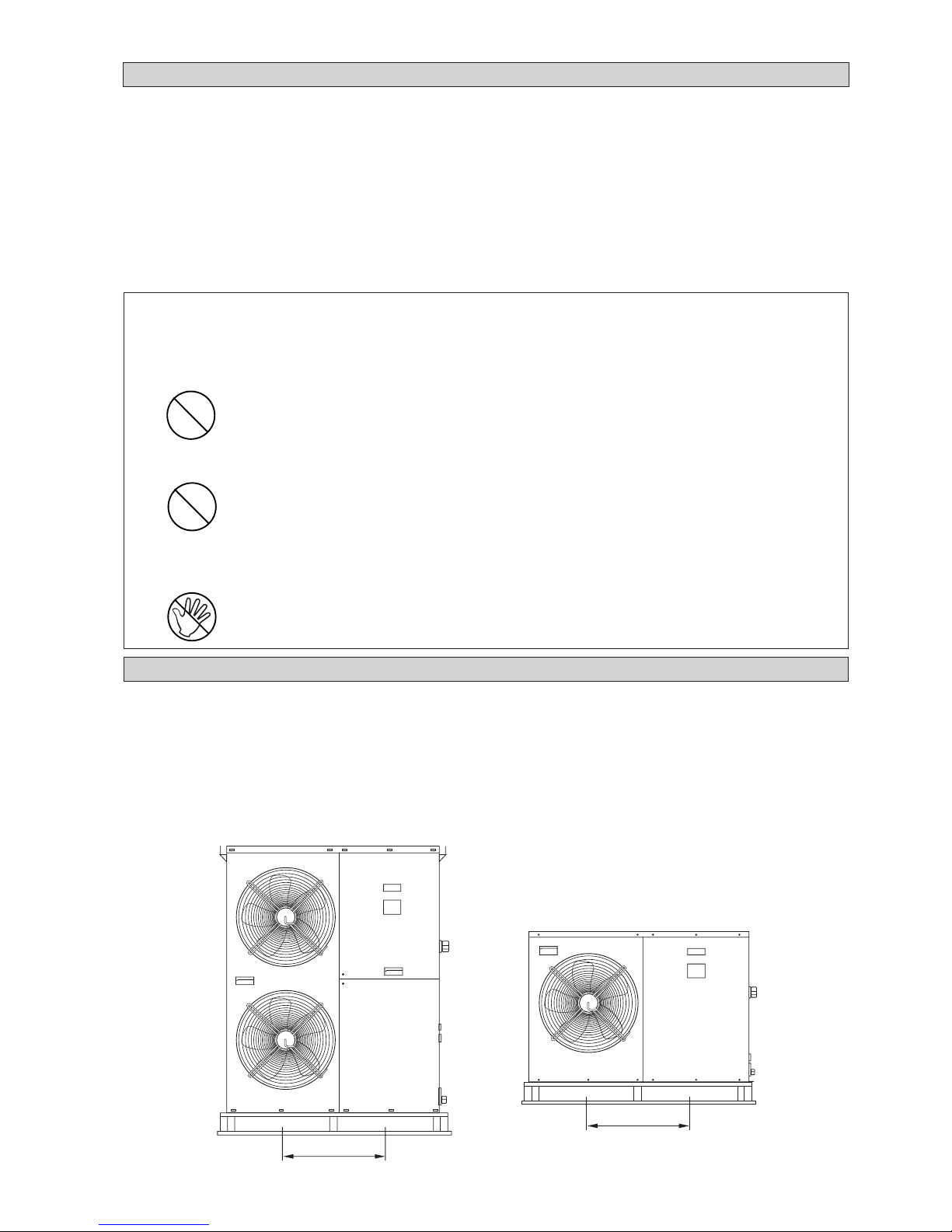
6-1
-
Рекомендуемые предохранители и размеры кабелей
стр. 8
- Наладка водяного контура стр. 11
- Контур хладагента стр. 11
- Специальные меры предосторожности
при обращении с R407С стр. 11
- Управление кондиционером стр. 12
- Обслуживание и уход стр. 13
- Устранение Неисправностей стр. 14
- Контроллер вентилятора (дополнитъльно)стр. 15
- Установка разъединителя стр. 15
!!
!!
! ОСТОРОЖНО
При установке обратите внимание на следующие важные моменты.
• Не устанавливайте блок в месте, где может произойти утечка горючего газа.
В случае утечки и скопления газа поблизости блока возможно воспламенение.
• Не перегружайте блок хладагентом.
Данный блок заправлен на заводе-изготовителе. Избыточная заправка приведет к
перегрузке или повреждению компрессора.
• Острые края и поверхность алюминиевых пластин теплообменника - это места,
представляющее опасность травмирования. Избегайте контакта с этими
местами.
УКАЗАТЕЛЬ
- Схема и размеры стр. i-ii
- Схема электрических соединений стр. iii-viii
- Схемы Разъединителя стр. ix-x
- Транспортировка стр. 1
- Место установки стр. 2
- Установка аппарата стр. 4
- Физические параметры стр. 5
- Трубопроводы и арматура
водяного контура стр. 7
- Электрические соединения стр. 7
- Электрические параметры стр. 8
ТРАНСПОРТИРОВКА
• Во избежание повреждения панелей, используйте для подъема блока широкозахватные траверсы или
вилочный погрузчик. На рис. 1 показаны размеры поддона для подъема блока. Избегайте резких
движений. Не убирайте поддон до установки блока в конечное положение.
При необходимости, для перемещения блоков мощностью свыше 11 кВт используйте кран. Убедитесь,
что подвесные ремни способны выдержать вес блока (вес блока указан в руководстве по эксплуатации).
Проследите за тем, чтобы подвесные ремни не соприкасались со змеевиком, верхней панелью и
передней панелью. Используйте подъемный кронштейн (прилагается наряду с данным руководством),
как показано на рис. 2. Перед перемещением блока на место слегка приподнимите его, чтобы проверить
равновесие. Не допускайте раскачивания и вращения блока.
Рисунок 1
577
550
Page 95

6-2
Русский
МЕСТО УСТАНОВКИ
• Монтажно-установочные работы должны выполняться уполномоченным дилером или подрядной
организацией, обладающей необходимой квалификацией. Ни в коем случае не устанавливайте блок
самостоятельно.
• Вокруг блока должно быть достаточно пространства для обтекания воздухом со всех сторон. В случае
установки блока в производственном помещении, исходящий воздух необходимо выводить наружу через
воздуховод.
• Для предотвращения вибрации и шума при работе аппарата необходимо обеспечить виброизоляцию.
• В случае установки блока на земле убедитесь, что выбранный участок не затапливается.
• При установке блока нужно оставить достаточно места для вентиляции, выполнения работ по
обслуживанию и ремонту. При выборе места руководствуйтесь следующими цифрами:
500 500
500
1500
Рисунок 3: Установка одного блока
ВОЗДУШНЫЙ
ПОТОК
ВОЗДУШНЫЙ
ПОТОК
ВОЗДУШНЫЙ
ПОТОК
МИН 500
Рисунок 2
КРЮК
ПОДВЕСНОЙ РЕМЕНЬ
Page 96

6-3
• При установке блока на полу его необходимо монтировать на бетонной плите. Толщина плиты должна
быть 100мм, а в ширину и длину она должна выступать на 50мм за пределы основания блока (рис. 5).
Располагайте плиту на расстоянии от здания, чтобы исключить вибрацию и шум.
• Для работы в режиме теплового насоса при наружной температуре ниже 0°C блок необходимо
устанавливать на высоте не менее 300мм над поверхностью земли. Это необходимо для предотвращения
накопления льда на раме и обеспечения нормальной работы в случае сильного снегопада.
• Блок необходимо выровнять по обеим осям. (Допуск менее 2мм на метр.)
50 50
100
Рисунок 5: Установка на полу
Примечание: Если не указано иное, все размеры показаны в мм.
500
1000
1000 500
1500
Рисунок 4: Установка нескольких блоков
ВОЗДУШНЫЙ
ПОТОК
ВОЗДУШНЫЙ
ПОТОК
ВОЗДУШНЫЙ
ПОТОК
ВОЗДУШНЫЙ
ПОТОК
МИН 500
ВОЗДУШНЫЙ
ПОТОК
ВОЗДУШНЫЙ
ПОТОК
ВОЗДУШНЫЙ
ПОТОК
Page 97

6-4
Русский
4AC/AC 020/025/030 C/CR
УСТАНОВКА АППАРАТА
!!
!!
! ОСТОРОЖНО
• Неправильное обращение с аппаратом во время установки может стать причиной протеканий,
поражения электрическим током или неправильной работы аппарата.
• Если необходимо переустановить или демонтировать аппарат, обращайтесь к своему дилеру.
• Не вставляйте в воздухозаборные и воздуховыпускные отверстия посторонних предметов, таких
как пальцы, палки и т.п.
• Не взбирайтесь на аппарат и не ставьте на него никаких предметов.
4AC/AC 040/050/060 C/CR
Page 98

6-5
ФИЗИЧЕСКИЕ ПАРАМЕТРЫ
Примечание: Для охлаждения номинальные значения указаны для температуры воды на входе в испаритель 12°C, на выходе из
испарителя 7°C, температуры окружающего воздуха 35°C.
Таблица A-1 : R407C - Только охлаждение
Модель 4AC020C 4AC025C 4AC030C 4AC040C 4AC050C 4AC060C
Номинальная охлаждающая способность
кВт 6,15 6,74 7,91 11,72 14,65 15,24
Рабочая масса кг 115,5 122,5 128 195 196,4 203,2
Заправка хладагентом R407C кг 1,13 1,85 1,65 3,40 3,35 3,45
Компрессор
1 ротационный компрессор
1 Спиральный компрессор
Система управления Электронное управление с ЖКИ
Теплообменник хладагент-вода Паяный пластинчатый теплообменник
Водяные соединения (BSP) дюйм 111111
Максимальное давление воды кПа 1000 1000 1000 1000 1000 1000
Контур жидкостного охлаждения
Насос
Высоконапорный циркуляционный
Горизонтальный многоступенчатый с односторонним всасыванием
Достижимое давление кПа 72,94 98,58 89,27 91,70 67,51 70,32
Водозаборное соединение (BSPT) дюйм 111111
Водовыпускное соединение (BSPT) дюйм 111111
Дренажное соединение (BSPT) дюйм 1/2 1/2 1/2 1/2 1/2 1/2
Объем закрытого водяного расширительного бака
литр 222555
Теплообменник хладагент-воздух
Диаметр трубки мм 9,52 9,52 9,52 9,52 9,52 9,52
Количество рядов 122222
Трубок в ряду 30 30 30 54 54 54
Расстояние между пластинами мм
1,27 1,59 1,59 1,59 1,59 1,59
Вентилятор
Диаметр дюйм 18 18 18 18/2 18/2 18/2
Количество лопастей 555555
Воздушный поток (высокая скорость)
м3/мин 62,3 62,3 62,3 62,3 62,3 62,3
Частота вращения (высокая скорость)
об/мин 910 920 920 920 920 920
Таблица A-2 : R22 - Только охлаждение
Модель AC020C AC025C AC030C AC040C AC050C AC060C
Номинальная охлаждающая способность
кВт 5,28 6,89 8,06 11,72 14,65 15,53
Рабочая масса кг 115,5 122,5 128 195 196,4 203,2
Заправка хладагентом R22 кг 1,13 1,80 1,56 2,68 3,10 3,10
Компрессор
1 ротационный компрессор
1 Спиральный компрессор
Система управления Электронное управление с ЖКИ
Теплообменник хладагент-вода Паяный пластинчатый теплообменник
Водяные соединения (BSP) дюйм 111111
Максимальное давление воды кПа 1000 1000 1000 1000 1000 1000
Контур жидкостного охлаждения
Насос
Высоконапорный циркуляционный
Горизонтальный многоступенчатый с односторонним всасыванием
Достижимое давление кПа 83,55 97,39 88,08 91,70 67,51 65,98
Водозаборное соединение (BSPT) дюйм 111111
Водовыпускное соединение (BSPT) дюйм 111111
Дренажное соединение (BSPT) дюйм 1/2 1/2 1/2 1/2 1/2 1/2
Объем закрытого водяного расширительного бака
литр 222555
Теплообменник хладагент-воздух
Диаметр трубки мм 9,52 9,52 9,52 9,52 9,52 9,52
Количество рядов 122222
Трубок в ряду 30 30 30 54 54 54
Расстояние между пластинами мм
1,27 1,59 1,59 1,59 1,59 1,59
Вентилятор
Диаметр дюйм 18 18 18 18/2 18/2 18/2
Количество лопастей 555555
Воздушный поток (высокая скорость)
м3/мин 62,3 62,3 62,3 62,3 62,3 62,3
Частота вращения (высокая скорость)
об/мин 910 920 920 920 920 920
Page 99

6-6
Русский
Примечание: Для охлаждения номинальные значения указаны для температуры воды на входе в испаритель 12°C, на
выходе из испарителя 7°C, температуры окружающего воздуха 35°C.
Для обогрева номинальные значения указаны для температуры воды на входе в испаритель 40°C, на выходе из
испарителя 45°C, температуры окружающего воздуха 7°C/6°C (сухой / смоченный термометр).
Таблица A-3 : R407C - Тепловой насос
Модель 4AC020CR 4AC025CR 4AC030CR 4AC040CR 4AC050CR 4AC060CR
Номинальная охлаждающая способность
кВт 4,98 6,45 7,33 11,72 13,48 14,95
Номинальная нагревательная способность
кВт 5,86 7,47 9,53 13,19 14,95 17,58
Рабочая масса кг 115,5 122,5 128,0 195,0 196,4 203,2
Заправка хладагентом R407C кг 1,50 1,75 1,60 3,00 3,45 4,00
Компрессор
1 ротационный компрессор
1 Спиральный компрессор
Система управления Электронное управление с ЖКИ
Теплообменник хладагент-вода Паяный пластинчатый теплообменник
Водяные соединения (BSP) дюйм 111111
Максимальное давление воды кПа 1000 1000 1000 1000 1000 1000
Контур жидкостного охлаждения
Насос
Высоконапорный циркуляционный
Горизонтальный многоступенчатый с односторонним всасыванием
Достижимое давление (охлаждение / обогрев)
кПа 87,21/76,47 100,89/92,77 93,89/76,38 91,70/74,54 82,15/63,75 74,67/35,27
Водозаборное соединение (BSPT) дюйм 111111
Водовыпускное соединение (BSPT) дюйм 111111
Дренажное соединение (BSPT) дюйм 1/2 1/2 1/2 1/2 1/2 1/2
Объем закрытого водяного расширительного бака
литр 222555
Теплообменник хладагент-воздух
Диаметр трубки мм 9,52 9,52 9,52 9,52 9,52 9,52
Количество рядов 122222
Трубок в ряду 30 30 30 54 54 54
Расстояние между пластинами мм
1,27 1,59 1,59 1,59 1,59 1,59
Вентилятор
Диаметр дюйм 18 18 18 18/2 18/2 18/2
Количество лопастей 555555
Воздушный поток (высокая скорость)
м3/мин 62,3 62,3 62,3 62,3 62,3 62,3
Частота вращения (высокая скорость)
об/мин 910 920 920 920 920 920
Таблица A-4 : R22 - Тепловой насос
Модель AC020CR AC025CR AC030CR AC040CR AC050CR AC060CR
Номинальная охлаждающая способность
кВт 5,28 6,74 8,06 11,72 13,48 15,53
Номинальная нагревательная способность
кВт 6,45 7,33 9,23 12,60 15,24 17,29
Рабочая масса кг 115,5 122,5 128,0 195,0 196,4 203,2
Заправка хладагентом R22 кг 1,55 1,93 1,75 3,00 3,65 4,00
Компрессор
1 ротационный компрессор
1 Спиральный компрессор
Система управления Электронное управление с ЖКИ
Теплообменник хладагент-вода Паяный пластинчатый теплообменник
Водяные соединения (BSP) дюйм 111111
Максимальное давление воды кПа 1000 1000 1000 1000 1000 1000
Контур жидкостного охлаждения
Насос
Высоконапорный циркуляционный
Горизонтальный многоступенчатый с односторонним всасыванием
Достижимое давление (охлаждение / обогрев)
кПа 83,55/69,27 98,58/93,89 88,08/78,76 91,70/81,42 82,15/60,12 65,98/39,62
Водозаборное соединение (BSPT) дюйм 111111
Водовыпускное соединение (BSPT) дюйм 111111
Дренажное соединение (BSPT) дюйм 1/2 1/2 1/2 1/2 1/2 1/2
Объем закрытого водяного расширительного бака
литр 222555
Теплообменник хладагент-воздух
Диаметр трубки мм 9,52 9,52 9,52 9,52 9,52 9,52
Количество рядов 122222
Трубок в ряду 30 30 30 54 54 54
Расстояние между пластинами мм
1,27 1,59 1,59 1,59 1,59 1,59
Вентилятор
Диаметр дюйм 18 18 18 18/2 18/2 18/2
Количество лопастей 555555
Воздушный поток (высокая скорость)
м3/мин 62,3 62,3 62,3 62,3 62,3 62,3
Частота вращения (высокая скорость)
об/мин 910 920 920 920 920 920
Page 100

6-7
P
ТРУБОПРОВОДЫ И АРМАТУРА ВОДЯНОГО КОНТУРА
• Все трубы водяного контура необходимо должным образом изолировать, чтобы не допустить потери
мощности и образования конденсата.
• Для обеспечения высокого качества воды установите сетчатый фильтр размером 40-60.
• Рекомендуется использовать стальные и медные трубы.
• Перед тем, как прикладывать вращательные усилия к соединительным трубам при выполнении
монтажных работ, необходимо зафиксировать трубопроводные конструкции блока с помощью зажимов,
чтобы уменьшить передаваемый на них крутящий момент.
• Рекомендуется монтировать трубы и принадлежности, как показано на Pис. 6.
• Кран для выпуска воздуха (воздушник) должен быть расположен в самой верхней точке, а дренажный
вентиль - в самой нижней точке водяного контура. После проверки на герметичность (0,6 МПа) откройте
воздушник, чтобы выпустить воздух, находящийся в трубах.
• Включите подачу чистой воды через водоприемное отверстие; включите насос и откачайте грязную
воду. После 30 минут работы насоса необходимо почистить фильтр.
•
После подключения всех трубопроводов и оборудования заполните водный контур. Проверьте
герметичность всех соединений. Не включайте аппарат, если обнаружены какие-либо протекания в системе.
• Для достижения оптимальной мощности убедитесь в отсутствии в системе воздушных пузырьков.
Наличие воздуха в системе приведет к ее неустойчивой работе.
!!
!!
! ОСТОРОЖНО
• Если аппарат не эксплуатируется длительное время, следите за тем, чтобы в трубопроводах не
оставалось воды.
Если аппарат не будет работать в зимнее время, воду необходимо спустить, иначе может произойти
растрескивание труб.
• Запрещается пить охлажденную воду из аппарата.
P
4AC/AC 020/025/030 C/CR
4AC/AC 040/050/060 C/CR
МАНОМЕТР
ЗАПОРНЫЙ
ВЕНТИЛЬ
ЗАПОРНЫЙ
ВЕНТИЛЬ
БАЛАНСИРОВОЧНЫЙ
ВЕНТИЛЬ
ТЕРМОМЕТР
ГИБКИЙ
ЗАПОРНЫЙ ВЕНТИЛЬ (В САМОЙ
НИЖНЕЙ ТОЧКЕ ДЛЯ ДРЕНАЖА)
ВОЗДУШНИК (В САМОЙ
ВЕРХНЕЙ ТОЧКЕ)
ВЕНТИЛЯТОРНЫЙ ТЕПЛООБМЕННИК /
БЛОК КОНДИЦИОНИРОВАНИЯ
ЗАПОРНЫЙ
ВЕНТИЛЬ
Рисунок 6
ТЕРМОМЕТР
ЗАПОРНЫЙ
ВЕНТИЛЬ
ЗАПОРНЫЙ
ВЕНТИЛЬ
БАЛАНСИРОВОЧНЫЙ
ВЕНТИЛЬ
ФИЛЬТР
ОБРАТНЫЙ
КЛАПАН
ВЕНТИЛЬ
ДОЛИВА
ПЕРЕПУСКНОЙ КЛАПАН
(ДИФФ ЕРЕНЦИАЛЬНОГО ТИПА)
МАНОМЕТР
ЗАПОРНЫЙ
ВЕНТИЛЬ
ЗАПОРНЫЙ
ВЕНТИЛЬ
БАЛАНСИРОВОЧНЫЙ
ВЕНТИЛЬ
ТЕРМОМЕТР
ГИБКИЙ
ЗАПОРНЫЙ ВЕНТИЛЬ (В САМОЙ
НИЖНЕЙ ТОЧКЕ ДЛЯ ДРЕНАЖА)
ВОЗДУШНИК (В САМОЙ
ВЕРХНЕЙ ТОЧКЕ)
ВЕНТИЛЯТОРНЫЙ ТЕПЛООБМЕННИК /
БЛОК КОНДИЦИОНИРОВАНИЯ
ЗАПОРНЫЙ
ВЕНТИЛЬ
ТЕРМОМЕТР
ЗАПОРНЫЙ
ВЕНТИЛЬ
ЗАПОРНЫЙ
ВЕНТИЛЬ
БАЛАНСИРОВОЧНЫЙ
ВЕНТИЛЬ
ФИЛЬТР
ОБРАТНЫЙ
КЛАПАН
ВЕНТИЛЬ
ДОЛИВА
ПЕРЕПУСКНОЙ КЛАПАН
(ДИФФ ЕРЕНЦИАЛЬНОГО ТИПА)
ЭЛЕКТРИЧЕСКИЕ СОЕДИНЕНИЯ
• При монтаже электрических соединений следуйте схеме, изображенной на корпусе блока.
• Не используйте водопроводный контур для заземления какого-либо электрического оборудования.
•
Во избежание поражения электрическим током необходимо установить внешний разъединитель (если он отсутствует).
 Loading...