

Page 1

BACnet VAV Actuator Installation Manual
IM 1037
Group: Controls
Part Number: IM 1037
Date: 3/4/2010
Supersedes: New
BACnet® VAV Actuator Installation Procedures
Model #: 2508021
Page 2

Table of Contents
Table of Contents .................................................................................................................. 2
Revision History.................................................................................................................................... 3
Reference Documents............................................................................................................................ 3
Limited Warranty .................................................................................................................................. 3
General Information .............................................................................................................. 4
Hazard Identification Messages ............................................................................................................ 4
Description ............................................................................................................................................ 5
Application............................................................................................................................................ 5
Component Data.................................................................................................................................... 5
Installation ............................................................................................................................. 6
Required Tools and Materials ............................................................................................................... 6
Installing a new BACnet VAV Actuator ............................................................................................... 6
To Install the BACnet VAV Actuator ............................................................................................... 6
To Wire the BACnet VAV Actuator ............................................................................................... 10
2 IM 1037
Page 3

Revision History
IM xxx Date Initial release
Reference Documents
Number Company Title Source
OM 1063 McQuay International VAV Actuator Owners Manual www.mcquay.com
Limited Warranty
Consult your local McQuay Representative for warranty details. Refer to Form 933-43285Y. To find your local
McQuay Representative, go to www.mcquay.com.
Notice
Copyright © 2010 McQuay International, Minneapolis MN. All rights reserved throughout the world.
McQuay International reserves the right to change any information contained herein without prior
notice. The user is responsible for determining whether this software is appropriate for his or her
application.
® ™ The following are tradenames or registered trademarks of their respective companies: BACnet
from the American Society of Heating, Refrigerating and Air-Conditioning Engineers, Inc.; Windows
from Microsoft Corporation; D-Net, McQuay and MicroTech III from McQuay International.
IM 1037 3
Page 4

General Information
This manual contains the information you need to install the BACnet® VAV Actuator on a VAV box.
Hazard Identification Messages
!
DANGER
Dangers indicate a hazardous situation that will result in death or serious injury if not
avoided.
!
WARNING
Warnings indicate potentially hazardous situations, which can result in property damage,
severe personal injury, or death if not avoided.
!
CAUTION
Cautions indicate potentially hazardous situations, which can result in personal injury or
equipment damage if not avoided.
WARNING
!
Electric shock hazard. Can cause personal injury or equipment damage.
This equipment must be properly grounded. Connections and service to the MicroTech III
Chiller Unit Controller must be performed only by personnel knowledgeable in the
operation of the equipment being controlled.
!
CAUTION
Static sensitive components. Can cause equipment damage.
Discharge any static electrical charge by touching the bare metal inside the control panel
before performing any service work. Never unplug cables, circuit board terminal blocks, or
power plugs while power is applied to the panel.
NOTICE
This equipment generates, uses and can radiate radio frequency energy and, if not
installed and used in accordance with this instruction manual, may cause interference to
radio communications. It has been tested and found to comply with the limits for a Class
A digital device, pursuant to part 15 of the FCC rules. These limits are designed to
provide reasonable protection against harmful interference when the equipment is
operated in a commercial environment. Operation of this equipment in a residential area
is likely to cause harmful interference in which case the user will be required to correct the
interference at his or her own expense. McQuay International disclaims any liability
resulting from any interference or for the correction thereof.
4 IM 1037
Page 5
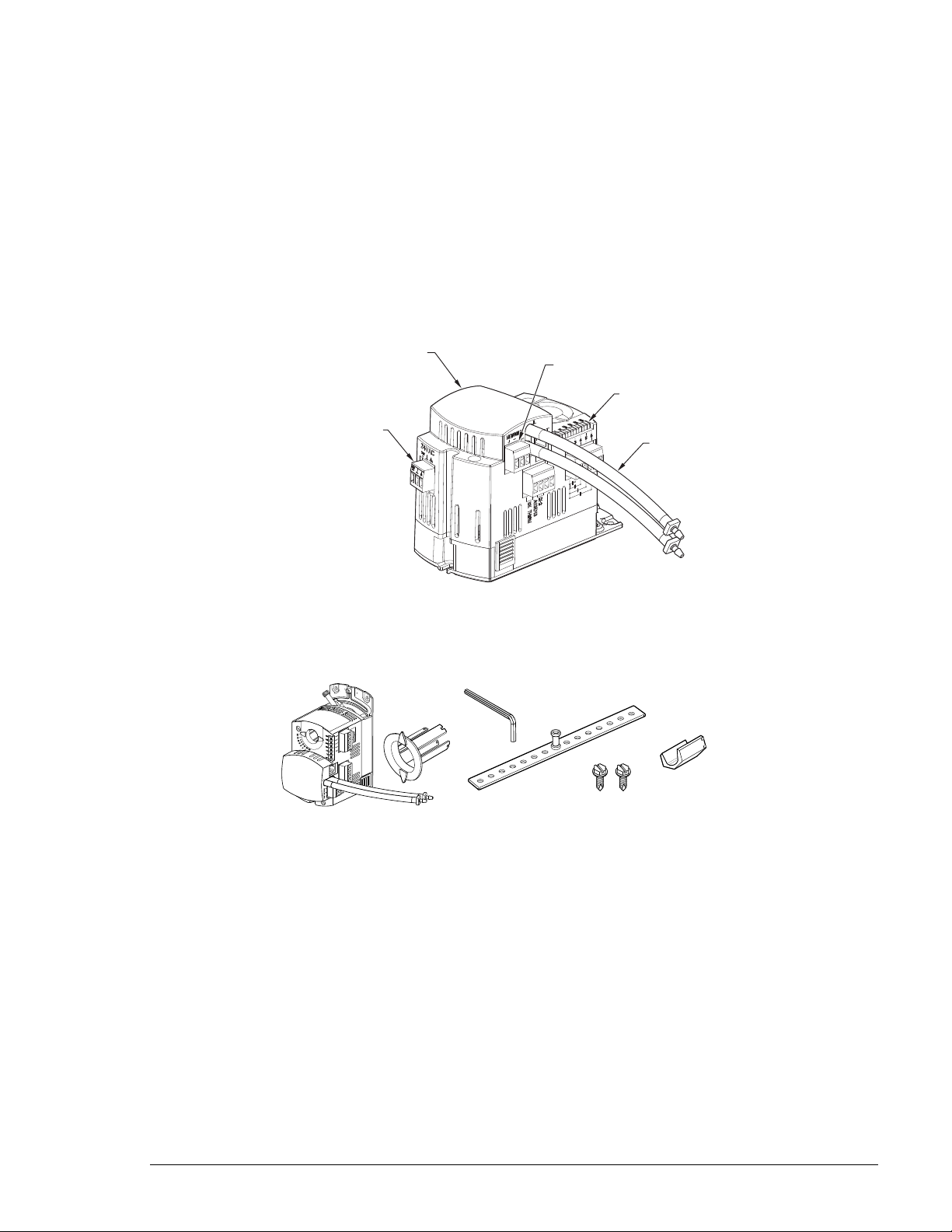
Air Velocity
Sensor
Power
Connection
Status/DO LEDs
BACnet
Connection
Airflow
Pickup Tubes
Description
These Installation Instructions describe direct-coupled mounting of the BACnet VAV Actuator, McQuay’s Nonspring Return Rotary Electronic Damper Actuator.
Application
This VAV Actuator can be used in control applications 2560 through 2567. For a full description of application
specifics please refer to the VAV Actuator Owners Manual (OM 1063).
Component Data
Figure 1 shows the BACnet VAV Actuator. Figure 2 shows the parts associated with the installation of the VAV
Actuator.
Figure 1. BACnet VAV Actuator.
90
45
TEC0495R1
STAT
a
b
Figure 2. Actuator Parts.
Parts List
a. Actuator with pre-terminated tubing
b. Position indicator
c. Mounting bracket
d. Self-tapping mounting screws
e. 4 mm hex key
f. 3/8-inch shaft adapter (8 to 10 mm shafts)
e
c
f
d
IM 1037 5
Page 6

Installation
!
The following section describes how to field install a new BACnet VAV Actuator or replace an existing
BACnet VAV Actuator on a McQuay VAV unit.
Expected Install Time: 25 minutes
CAUTION
Electrostatic discharge hazard. Can cause equipment damage.
This equipment contains sensitive electronic components that may be damaged by
electrostatic discharge from your hands. Before you handle a communications module, you
need to touch a grounded object, such as the metal enclosure, in order to discharge the
electrostatic potential in your body.
Required Tools and Materials
• 4 mm hex wrench
• Small, flat-blade screwdriver
• 1/4-inch Hex drill/driver set
• Marker or pencil
• Torque Wrench
Installing a new BACnet VAV Actuator
Follow these steps to install a BACnet VAV Actuator on the VAV unit.
To Install the BACnet VAV Actuator
WARNING
!
Electric shock hazard. Can cause personal injury or equipment damage.
This equipment must be properly grounded. Only personnel knowledgeable in the operation of the
equipment being controlled must perform connections and service to the BACnet VAV Actuator.
1. Determine the size of the damper shaft.
• If the damper shaft is 1/2-inch, proceed to Step 2.
NOTE: The actuator comes with a factory-installed 1/2-inch damper shaft guide.
• If the damper shaft is 5/8-inch:
a. Remove the 1/2-inch shaft guide, Figure 3.
6 IM 1037
Page 7

TEC0498R1
Mounting
3/8-inch
8...10 mm shafts
~
~
STAT
45
90
TEC0497R1
Figure 3. Removing the 1/2-inch Shaft Guide.
b. Proceed to Step 2.
• If the damper shaft is 3/8-inch:
a.
Remove the 1/2-inch shaft guide, Figure 3.
b.
Use the 3/8-inch adapter, provided in the actuator packaging, Figure 4. Hold the shaft insert so
that the raised tabs are inserted last when placing the insert into the back of the actuator.
Figure 4. Installing the 3/8-inch Shaft Adapter.
c.
Proceed to Step 2.
2. Determine the damper blade rotation, clockwise or counterclockwise to open, Figure 5.
CLOCKWISE
TO OPEN
TEC0499R1
"0"
Figure 5. Damper Rotation.
COUNTER
CLOCKWISE
TO OPEN
• If the blades will rotate counterclockwise, slide the manual override switch to manual, and move the
adjustment lever to the right. Return the switch to automatic, Figure 6.
• If the blades will rotate clockwise, slide the manual override switch to manual, and move the
adjustment lever to the left. Return the switch to automatic, Figure 6.
IM 1037 7
Page 8

ADJUSTMENT
TEC0501R1
TEC0503R1
STAT
45
90
LEVER
90
45
STAT
TEC0500R1
MANUAL
Figure 6. Setting the Direction of Rotation.
3. Close the damper blades, Figure 8.
Figure 7. Setscrew in Shaft Hole.
4. Mark the end of the damper shaft with a pencil/marker, Figure 8.
5. Tighten the setscrew until the first thread can be seen in the shaft hole, Figure 7.
Figure 8. Mounting the Actuator.
6. Mount the actuator on the damper shaft, Figure 8.
7. Install the position indicator, Figure 9.
8. Tighten the adjustment lever to the proper torque listed:
8 IM 1037
Page 9

TEC0502R1
1/2
1/2
CENTER THE
MOUNTING BRACKET
IN THE SLOT
CAUTION:
These holes for use
with accessory kits only.
Do not use in the
installation of directcoupled applications.
1/4 in.
Hex Drive
• 70 +/- 5 inch-pounds for solid metal
• 37 +/- 2 inch-pounds for plastic graphite composite (hollow metal shafts require an insert to
prevent shaft damage).
4 mm
90
45
STAT
TEC0504R1
Figure 9. Position Indicator and Adjustment Lever.
9. Attach the mounting bracket, Figure 10.
NOTE: When installing the mounting bracket directly on the ductwork, be sure to position the bracket
so that the screws do not obstruct the damper blade movement inside the box.
Figure 10. Installing the Mounting Bracket.
10. Connect the airflow tubing for the Differential Pressure Sensor.
• RED connects to HIGH.
• BLUE connects to LOW.
IM 1037 9
Page 10

TEC0507R1
.156
(4)
3.437
(87)
5.368
(136.35)
min. 6 inch
152.4 mm
.937
(94)
min.
4 inch
101.6 mm
.4375
(11)
min. 4 inch
100 mm
.0312
(0.8)
5.574
(141.58)
2.677
(68)
min.
.25 inch
6 mm
min. 8 inch
203.2 mm
4.189
(106.39)
min. .375 inch
10 mm
.8126
(21)
2.948
(74.88)
To Wire the BACnet VAV Actuator
WARNING
!
Electric shock hazard. Can cause personal injury or equipment damage.
This equipment must be properly grounded. Only personnel knowledgeable in the operation of the
equipment being controlled must perform connections and service to the BACnet VAV Actuator.
WARNING: Installations requiring CE Conformance
• All wiring for CE rated actuators must be Separated Extra Low Voltage (SELV) or Protective Extra
Low Voltage (PELV) per HD384-4-41.
• Use safety-isolating transformers (Class III transformer) per EN 61558. They must be rated for 100%
duty cycle.
• Over current protection for supply lines is maximum 4A.
Figure 11. BACnet VAV Actuator Dimensions in Inches (Millimeters).
10 IM 1037
Page 11

Wiring Instructions
Wiring the 24VSC
Power
Wiring the power connector
as shown in the diagram
below. Note the orientation
of the power connector
and the location of the
Earth (E) , Common (C)
and Hot (H) connections
before wiring.
TEC0514R1
24V
Actuator
24V
24VAC Line
24VAC Neutral
Earth
Field Wiring Neutral Bond Wire
24VAC
24V
24V
Dependent On
Local Codes
Required If Primary
Is Over 150 VAC
Figure 12. Power Wiring.
Digital Outputs (DO):
The Digital Outputs on the VAV Actuator are dry output Triac type outputs. 24 VAC must be applied to the
“C” pin of the DO connector. The side view of the Actuator shows output pin details.
By providing dry output Triac DO’s, the application can switch either Phase or Neutral depending on
application needs. In a 24 VAC circuit, neutral is determined by which side of the transformer is earth
grounded. If neither side is earth grounded (at the transformer) then the 24 VAC is considered a floating
(isolated) source.
24Vac 5 00ma
per Triac Max.
TEC0511R1
Interna l
Thermal Overloa d
C
DO3
DO4
DO5
DO6
24 Va c (50/60 Hz)
Heat St age1
Heat St age2
Heat St age3
FAN
Figure 13. BACnet VAV Actuator with Electric Heat and Fan.
IM 1037 11
Page 12

TEC0512R1
24Vac 5 00ma
per Triac Max.
DO3
DO4
DO5
DO6
Interna l
Thermal Overloa d
FAN
Spare DO
M
Valve Act uator
Open
Close
C
24 Va c (50/60 Hz)
Figure 14. BACnet VAV Actuator with Hot Water Reheat, Fan and Spare DO.
DI
10K Therm
-8Vdc
+5Vdc
+9Vdc
1
2
3
4
TEC0513R1
Figure 15. Wiring for D12/A13.
Wiring DI Common (pin 4) to 10K Thermistor - 8Vdc (pin 2) incorrectly, will cause the actuator to shut
down. No damage will occur. When the wiring is corrected the actuator will resume operation.
DO/DI Wiring Diagrams
DO 6
DO 5
DO 4
DO 3
ROOM TEMPERATURE SENSOR
DI 2
AI3 / DI3
TEC2560WDR1
Figure 16. Application 2560 Wiring Diagram (Cooling Only).
AUTOZERO MODULE (OPTIONAL) OR SPARE DO
SPARE DOS
"COMMON" TERMINATION FOR ALL DOs
WALL SWITCH (OPTIONAL)
OR SPARE DI (DRY CONTACT)
SPARE AI (10K THERMISTOR)
OR SPARE DI (DRY CONTACT)
12 IM 1037
Page 13

TEC2561WDR1
AUTOZERO MODULE (OPTIONAL) OR SPARE DO
DI 2
DO 6
DO 5
DO 4
DO 3
AI3 / DI3
"COMMON" TERMINATION FOR ALL DOs
SPARE DOS
WALL SWITCH (OPTIONAL)
OR SPARE DI (DRY CONTACT)
DUCT TEMPERA
TURE SENSOR
OR (10K THERMISTOR)
ROOM TEMPERATURE SENSOR
ELECTRIC HEAT STAGE 3
ELECTRIC HEAT STAGE 2
ELECTRIC HEAT STAGE 1
AUTOZERO MODULE (OPTIONA
L) OR SPARE DO
DI 2
DO 6
DO 5
DO 4
DO 3
AI3 / DI3
"COMMON" TERMINATION FOR ALL DOs
WALL SWITCH (OPTIONAL)
OR SPARE DI (DRY CONTACT)
SPARE AI (10K THERMISTOR)
OR SP
ARE DI (D
RY CONTACT)
ROOM TEMPERATURE SENSOR
TEC2562BWDR1
2 - POSITION VALVE
AUTOZERO MODULE (OPTIONAL) OR SPARE DO
DI 2
DO 6
DO 5
DO 4
DO 3
AI3 / DI3
"COMMON" TERMINATION FOR ALL DOs
SPARE DOS
WALL SWITCH (OPTIONAL)
OR SPARE DI (DRY CONTACT)
SPARE AI (10K THERMIS
TOR)
OR SP
ARE DI (D
RY CONTACT)
ROOM TEMPERATURE SENSOR
TEC2563AWDR1
VALVE
ACTUATOR
AUTOZERO MODULE (OPTIONAL) OR SPARE DO
DI 2
DO 6
DO 5
DO 4
DO 3
AI3 / DI3
"COMMON" TERMINATION FOR ALL DOs
SPARE DO
WALL SWITCH (OPTIONAL)
OR SPARE DI (DRY CONTACT)
SPARE AI (10K THERMIST
OR)
OR SP
ARE DI (DRY CONTACT)
ROOM TEMPERATURE SENSOR
CLOSED
OPEN
Figure 17. Application 2561 Wiring Diagram (Heating or Cooling).
Figure 18. Application 2562 Wiring Diagram (Electric Heat Stages).
Figure 19. Application 2562 Wiring Diagram (Baseboard Radiation).
IM 1037 13
Figure 20. Application 2563 Wiring Diagram (Hot Water Heat and Spare DO).
Page 14

TEC2563BWDR1
VALVE
ACTUATOR
DI 2
DO 6
DO 5
DO 4
DO 3
AI3 / DI3
"COMMON" TERMINATION FOR ALL DOs
WALL SWITCH (OPTIONAL)
OR SPARE DI (DRY CONTACT)
SPARE AI (10K THERMISTOR)
OR SP
ARE DI (DRY CONTACT)
ROOM TEMPERATURE SENSOR
CLOSED
OPEN
VALVE
ACTUATOR
CLOSED
OPEN
TEC2564and2566WDR1
FAN
ELECTRIC HEAT STAGE 3
ELECTRIC HEAT STAGE 2
ELECTRIC HEAT STAGE 1
DI 2
DO 6
DO 5
DO 4
DO 3
AI3 / DI3
"COMMON" TERMINATION FOR ALL DOs
WALL SWITCH (OPTIONAL)
OR SPARE DI (DRY CONTACT)
SPARE AI (10K THERMISTOR)
OR SP
ARE DI (D
RY CONTACT)
ROOM TEMPERATURE SENSOR
TEC2565and2567WDR1
FAN
VALVE
ACTUATOR
DI 2
DO 6
DO 5
DO 4
DO 3
AI3 / DI3
"COMMON" TERMINATION FOR ALL DOs
SPARE DO
WALL SWITCH (OPTIONAL)
OR SPARE DI (DRY CONTACT)
SPARE AI (10K THERMISTOR)
OR SPARE DI (DRY CONTACT)
ROOM TEMPERATURE SENSOR
CLOSED
OPEN
Figure 21. Application 2563 Wiring Diagram (Hot Water Heat 2 Motors).
Figure 22. Application 2564/Application 2566 Wiring Diagram (Electric Heat Stage and Series or Parallel Fan).
Figure 23. Application 2565/Application 2567 Wiring Diagram (Hot Water Heat and Series or Parallel Fan).
The installation is now complete.
14 IM 1037
This document contains the most current product information as of this printing. For the most
current product information, please go to www.mcquay.com. All McQuay equipment is sold
pursuant to McQuay’s Standard Terms and Conditions of Sale and Limited Warranty.
©2010 McQuay International ● www.mcquay.com ● 800-432-1342
 Loading...