


iScout® System
User’s Manual
April 2, 2008
Version 1.2
McQ Inc.
1551 Forbes Street
Fredericksburg, VA 22405
(540) 373-2374
info@mcqinc.com
OmniSense® and iScout® are the Registered Trademarks of McQ Inc.
© Copyright McQ Inc. April 2008


Table of Contents
1 INTRODUCTION .............................................................................................................. 1
1.1 iScout® Sensor Description ......................................................................................... 2
1.1.1 iScout® Features ..................................................................................................... 3
1.2 Wireless Mobile Relay (WMR) Description ................................................................ 5
1.2.1 WMR Features ........................................................................................................ 5
1.3 Long Haul Communications Node (LHCN) Description .............................................. 6
1.3.1 LHCN Features........................................................................................................ 6
1.4 Handheld Programmer Monitor (HHPM) Description .................................................. 7
1.4.1 HHPM Features ....................................................................................................... 7
2 ISCOUT® LONG HAUL COMMUNICATIONS NODE SET UP ..................................... 8
2.1 Mission Planning ......................................................................................................... 8
2.1.1 Location .................................................................................................................. 8
2.1.2 Communications ...................................................................................................... 8
2.2 OmniSense LHCN Operation ...................................................................................... 9
2.2.1 LHCN Installation ................................................................................................... 9
Installing the Local Comms Antenna to the LHCN Housing ............................................ 9
Installing the Iridium Antenna to the LHCN Housing .................................................... 10
Installing Batteries into Battery Housing ....................................................................... 10
Connecting the Battery Box to the LHCN Housing ........................................................ 11
Changing the Batteries in the LHCN Housing ............................................................... 12
2.2.2 Configuring the LHCN .......................................................................................... 12
Establishing Communications with the LHCN............................................................... 13
Configuring the LHCN .................................................................................................. 14
3 ISCOUT® SENSOR SET UP ........................................................................................... 17
3.1 Set Up Procedure for iScout® Sensor ........................................................................ 18
3.2 iScout® Normal Mode .............................................................................................. 21
3.3 Sleep Mode ............................................................................................................... 21
3.4 Tamper ...................................................................................................................... 22
4 ISCOUT® DEPLOYMENT GUIDANCE ......................................................................... 23
4.1 Using the PIR Sensor ................................................................................................. 23
4.2 Using the Optional Switch Closure Detection and Control Functions ......................... 24
4.3 Seismic Algorithms ................................................................................................... 26
4.4 Magnetic Algorithms ................................................................................................. 26
4.5 Acoustic Blast Algorithms ......................................................................................... 26
5 HAND-HELD PROGRAM MONITOR (HHPM) USER GUIDE ...................................... 27
5.1 Primary Operations .................................................................................................... 27
5.1.1 Aligning the Touch Screen .................................................................................... 27
5.1.2 Power Key Features ............................................................................................... 27
Turn Backlight On/Off .................................................................................................. 27
Power Menu .................................................................................................................. 27
5.1.3 Using the Stylus..................................................................................................... 28
HHPM Keyboards ......................................................................................................... 28
Performing a Clean Boot ............................................................................................... 29
Notification LEDs ......................................................................................................... 29
iScout® System User’s Manual i
© McQ Inc 2008

5.1.4 GPS ....................................................................................................................... 30
5.2 Settings on Your HHPM ............................................................................................ 30
5.2.1 Backlight for Display and Keypad ......................................................................... 30
5.2.2 Clock Settings ....................................................................................................... 31
5.2.3 Power .................................................................................................................... 31
5.2.4 Memory ................................................................................................................. 32
5.2.5 System Information ............................................................................................... 32
5.2.6 Volume .................................................................................................................. 33
5.3 Quick Start ................................................................................................................ 33
5.3.1 Creating and Using a Map ..................................................................................... 33
5.3.1.1 Creating a Map .............................................................................................. 34
5.3.2 Sensor Map............................................................................................................ 35
5.3.3 Navigating the Map ............................................................................................... 35
Moving Using the Map Menu ........................................................................................ 35
5.3.4 Using Sensors ........................................................................................................ 36
5.3.5 Further Information ............................................................................................... 36
5.4 Window Menu ........................................................................................................... 36
5.4.1 Window Menu: Legend ........................................................................................ 37
5.4.2 Window Menu: Preferences .................................................................................. 37
Preferences: Comm Ports ............................................................................................. 38
Preferences: HHPM Settings ........................................................................................ 38
5.4.3 Window Menu: Detections ................................................................................... 41
5.4.4 Window Menu: Device List .................................................................................. 42
5.4.5 Window Menu: Images ......................................................................................... 42
5.4.6 Window Menu: Switch Sensor .............................................................................. 42
5.4.7 Window Menu: GPS On ....................................................................................... 42
5.4.8 Window Menu: Exit ............................................................................................. 42
5.5 Devices Menu............................................................................................................ 43
5.5.1 Devices Menu: Discover Devices ......................................................................... 43
5.5.2 Devices Menu: Request Status .............................................................................. 43
Device Name ................................................................................................................. 43
Status Time ................................................................................................................... 43
On Time ........................................................................................................................ 43
Battery .......................................................................................................................... 43
BITE Failures ................................................................................................................ 43
Mode ............................................................................................................................. 44
Report Interval .............................................................................................................. 44
Communication Statuses ............................................................................................... 44
5.5.3 Devices Menu: Command Image .......................................................................... 44
5.5.4 Devices Menu: Command Switch ......................................................................... 45
5.5.5 Devices Menu: Configure Device ......................................................................... 46
Location ........................................................................................................................ 46
Configuring Comms ...................................................................................................... 47
Transducers ................................................................................................................... 48
Algorithms .................................................................................................................... 48
Sleep ............................................................................................................................. 49
iScout® System User’s Manual ii
© McQ Inc 2008

5.5.6 Devices Menu: Configure PTZ ............................................................................. 49
5.5.7 Devices Menu: Set Operational ............................................................................. 49
5.5.8 Devices Menu: Switch CDIF ................................................................................ 50
6 TECHNICAL SUPPORT .................................................................................................. 51
6.1 Maintenance .............................................................................................................. 51
6.2 Training ..................................................................................................................... 51
6.3 Installation................................................................................................................. 51
6.4 Configuration Management and Program Support ..................................................... 51
6.5 Contact Information................................................................................................... 51
7 END USERS LICENSE AGREEMENT ........................................................................... 53
8 APPENDIX A FCC (UNITED STATES) CERTIFICATION ........................................... 58
iScout® System User’s Manual iii
© McQ Inc 2008

Table of Figures
Figure 1-1: iScout® Kit with LHCN (left) and iScout Basic Kit (right) ...................................... 1
Figure 1-2: iScout® Communications ........................................................................................ 2
Figure 1-3: iScout® Sensor ........................................................................................................ 3
Figure 1-4: The Wireless Mobile Relay (WMR) ......................................................................... 5
Figure 1-5: The Handheld Programmer Monitor (HHPM), left and HHPM Sensor Map, right .... 7
Figure 2-1: LHCN Connectors ................................................................................................... 9
Figure 2-2: The Battery Box contains the housing that the batteries plug into ........................... 10
Figure 2-3: Devices Menu (left), Configuration Editor (center) and Comms Tab (right) ........... 14
Figure 2-4: Devices Menu (left) and LHCN Status Screen (right) ............................................. 15
Figure 2-5: LHCN Configuration Editor | Algorithms Tab ....................................................... 16
Figure 3-1: Hand Held Programmer Monitor (HHPM) and Wireless Remote Relay (WMR) .... 17
Figure 3-2: Comms Port Window............................................................................................. 18
Figure 3-3: Window Menu ....................................................................................................... 19
Figure 3-4: a. Battery /Switch cover b. Polarity Markings c. Lithium AA Batteries ............ 19
Figure 3-5: Battery Switch Cover Rotated to ON Position ........................................................ 20
Figure 3-6: PIR Lens Cover (observe LED indication through the lens) ................................... 20
Figure 3-7: HHPM Algorithms Tab .......................................................................................... 22
Figure 4-1: iScout® Sensor and Switch Cable .......................................................................... 24
Figure 4-2: Switch closure Specifications and Usage Guidelines .............................................. 25
Figure 5-1: Power Menu .......................................................................................................... 27
Figure 5-2: Keyboard Icon ....................................................................................................... 28
Figure 5-3: Windows Alphabetic and Numeric Keyboards ........................................................ 28
Figure 5-4: Battery Status and Notification LEDs .................................................................... 29
Figure 5-5: Nomad Settings Screen .......................................................................................... 30
Figure 5-6: Settings | Backlight ................................................................................................. 30
Figure 5-7: Settings | Time Screen ........................................................................................... 31
Figure 5-8: Settings | Power Screen .......................................................................................... 31
Figure 5-9: Settings | Memory Screen ...................................................................................... 32
Figure 5-10: Settings | System Information Screen ................................................................... 32
Figure 5-11: Settings | Sounds and Notifications Screen ........................................................... 33
Figure 5-12: Map Menu | Add Layer (left) and Open File Screen (right) .................................. 34
Figure 5-13: HHPM Map Screen (left), Map Menu (center) and Save As Screen (right) ........... 34
Figure 5-14: Sensor Map .......................................................................................................... 35
Figure 5-15: Map Menu Options .............................................................................................. 35
Figure 5-16: Window Menu ..................................................................................................... 36
Figure 5-17: Legend Screen ..................................................................................................... 37
Figure 5-18: Preferences Menu ................................................................................................ 37
Figure 5-19: Comms Port Window ........................................................................................... 38
Figure 5-20: HHPM Settings Preferences ................................................................................. 38
Figure 5-21: MGRS Display ..................................................................................................... 41
Figure 5-22: Device List Left and Right Screens ...................................................................... 42
Figure 5-23: Current Image Screen .......................................................................................... 42
Figure 5-24: Devices Menu ...................................................................................................... 43
Figure 5-25: Device Status Window ......................................................................................... 43
Figure 5-26: Device Status Window | Communications Status Table ........................................ 44
iScout® System User’s Manual iv
© McQ Inc 2008

Figure 5-27: Command Switch Screen ..................................................................................... 45
Figure 5-28: HHPM Location Panel ......................................................................................... 46
Figure 5-29: Mark Button | No GPS Fix .................................................................................. 46
Figure 5-30: HHPM Location Panel with GPS Off ................................................................... 47
Figure 5-31: HHPM Comms Panel ........................................................................................... 47
Figure 5-32: HHPM Transducers Panel .................................................................................... 48
Figure 5-33: HHPM Algorithms Panel ..................................................................................... 48
Figure 5-34: HHPM Sleep Panel .............................................................................................. 49
Figure 5-35: Begin Operation Confirmation ............................................................................. 49
Figure 5-36: Switch CDIF Message ......................................................................................... 50
iScout® System User’s Manual v
© McQ Inc 2008


1 Introduction
Figure 1-1: iScout® Kit with LHCN (left) and iScout Basic Kit (right)
The iScout® Kit (Figure 1-1, left) includes iScout® sensors, a Wireless Mobile Relay
(WMR), a Long Haul Communications Node (LHCN) and a Handheld Programmer
Monitor (HHPM). The iScout® sensor is the device that detects activity within a specific range
and reports the information to the user. The iScout® sensor reports the information to the
WMR, which then transfers the information to HHPM over the Bluetooth link. The LHCN is a
bridging device that allows the sensor network to be remotely monitored via the Iridium satellite
system. Each kit has up to six iScout sensors; one HHPM; one WMR; one LHCN; one battery
housing for three BA series batteries; two sets of lithium AA batteries for the iScout sensors; one
charger for the HHPM and the WMR; an external battery pack connector; microphone port water
sealing plug; PIR lens protective caps for each iScout; antennas for each iScout, for the WMR,
and satellite antenna and local comms antenna for the LHCN; optional switch closure cables if
this option is provided; and a copy of this iScout System User’s Manual. Also available is the
iScout Basic Kit (Figure 1-1, right) which does not include the LHCN.
iScout® System User’s Manual 1
© McQ Inc 2008

Figure 1-2: iScout® Communications
Figure 1-2 shows how the iScout® sensors, the WMR, the LHCN, the ISU and the HHPM
communicate with each other and the OmniSense® Backend SAD.
Communications in the iScout® system take place over the local communication links and via
the Iridium satcom link. The communication between an iScout® sensor node and the Wireless
Mobile Relay (WMR) is through a 900 MHz local communications radio. The WMR is
responsible for taking the data sent by the iScout® sensor node and sending the same
information to the HHPM over the Bluetooth link. The HHPM is responsible for establishing the
Bluetooth link between the WMR and HHPM through the OmniSense® program. Once the link
between the WMR and the HHPM has been established, the data will appear on the HHPM from
the iScout® with no interference. Also available is communication with the iScout sensor via
either the OmniSense ISU or via a LHCN relay.
1.1 iScout® Sensor Description
The iScout® sensor node’s purpose is to detect activity in a specific area based on the transducer
that is being used. The iScout® sensor (Figure 1-3) is equipped with GPS positioning capability
and a 900 MHz communications radio as well as internal transducers that include a geophone, a
microphone, a passive infrared module, and a magnetometer. The external connectors for the
iScout® sensor include an optional connector for a switch closure cable and an antenna for the
iScout® System User’s Manual 2
© McQ Inc 2008

local communications. An optional external battery pack connector is also available. The
iScout® sensor is powered with 2 AA batteries and the operator has the choice of whether to use
alkaline or lithium, although 4 lithium batteries are delivered with each sensor. The iScout sensor
also reports status messages over a configurable interval and alerts the user when the sensor is
tampered. The iScout® sensor can communicate with OmniSense® sensors through the 900
MHz link to command images and send detections over Iridium if necessary. A Long Haul
Comms Node (LHCN) can send iScout messages and forward backend command and control
messages via the Iridium satcom link.
Figure 1-3: iScout® Sensor
1.1.1 iScout® Features
Size: 3 ½ x 3 ½ x 1 ¾ Inches
Weight: 8 Oz
Op Temperature Range: –20˚C to +60˚C
Power: Two internal AA Batteries (Lithium preferred) or External Battery Pack (One BA 5390)
Operating Lifetime:
Ø Internal Batteries: 15 – 45 Days (Activity Dependent)
Ø External Battery Pack: 1 – 3 Years (Activity Dependent)
Sensors: Seismic, Acoustic, Magnetic, Passive IR
Position: GPS Receiver
iScout® System User’s Manual 3
© McQ Inc 2008

Communications:
Ø 902 to 928 MHz, Frequency Hop, Two Way, External ½ Wave Antenna, Star
Architecture
Ø Long Haul Comms Node (LHCN) Relay: IRIDIUM to SADU Backend User
Interface, Local Comms Relay to Wireless Mobile Relay
Ø Wireless Mobile Relay: Local Comms Relay to User via Bluetooth RF Link to
Handheld Display
Ø Range (Line of Sight):
300 – 500m Ground to Ground Height
500 – 1000m Ground to 1m Height
>1000m 1m to 1m Height
Data Structure: Common Data Interchange Format (CDIF)
Data Rate: Up to 115 Kbps
Field User Display: PDA or Handheld PC, Map Based Display, Sensor Detection Reports,
Sensor Command and Control, Sensor Status Reports
Fully Compatible with OmniSense®
Ø Commands OmniSense® Pictures
Ø Communicates Through OmniSense®
Positive Indication of Unit Comms Link Status
Accurate Timestamp of Activities From GPS and Internal Clock
Emplacement Mode for Easy Installation and Set Up
Normal Mode Provides Automated Operation
Sleep Mode Programmable by Operator
Tamper Report with Option to Disable Sensor or Continue Tamper Reports
Unique ID for Each Sensor Plus User Programmed Alphanumeric Sensor Description
Detection Algorithms:
Operator Configurable Detection Algorithms
Ø Seismic: On/Off with Four Sensitivity Levels; Vehicles, People, or Both;
Ø Magnetic: On/Off
Ø Acoustic: On/Off with Two Sensitivity Levels; Blast
Ø PIR: On/Off
Ø External Switch Detection (optional)
Ø External Switch Control (optional)
Target Detection Ranges:
Ø Vehicles: Seismic: up to 80m / PIR: up to 60m / Magnetic: up to 3m
Ø Personnel: Seismic: up to 30m
Ø Other: Gunfire/Explosion: up to 10m
iScout® System User’s Manual 4
© McQ Inc 2008

1.2 Wireless Mobile Relay (WMR) Description
The WMR (Figure 1-4) is used solely to convert the
messages sent from the iScout® to the HHPM for the user
to see. The WMR receives sensor messages with a 900
MHz local communications radio and transmits to the
HHPM with a Bluetooth module. This allows the user to
receive instantaneous messages from the sensor on the
HHPM without the requirement of an Situation Awareness
Display Unit (SADU) server. The only step that a user is
required to perform is to link the HHPM with the WMR
once the WMR has been powered on. To power on the
WMR, the operator only needs to turn the switch located
on the top of the box. When the switch is turned to the On
position, the Power LED turns green. If the WMR is in the
Off position, the Power LED is not on. The second LED,
Figure 1-4: The Wireless Mobile Relay
(WMR)
1.2.1 WMR Features
Battery Powered: Lithium Ion- Rechargeable/Battery Indicator LED
On LED
Power Switch: Rotary On/Off
Operating Life: Approx 24 Hours
Size: 5 in X 3in X 2in
Weight: 10oz
Antenna: 900 MHz Whip
Communications:
900 MHz Transceiver Link to iScout® Sensors
2.4 GHz Bluetooth Link to Handheld Monitor
or Battery LED, on the WMR shows when the unit is
being charged. The unit is red when it is charging and
green when the charge has exceeded 90% of battery
capacity. The connector for the battery charger is located
on the side of the unit. The battery charger is the same
model as the one used for the HHPM and is included in
the kit.
iScout® System User’s Manual 5
© McQ Inc 2008

1.3 Long Haul Communications Node (LHCN) Description
The OmniSense Model 2501 Long Haul Communications Node (LHCN) provides a satellite
based Terrestrial Network (TNet) communications hub for a small field of sensors. Its sole duty
is to relay sensor messages to and from the OmniSense Backend. The LHCN allows for the
deployment of TNet compatible sensors for long-term monitoring in remote locations.
The LHCN operates on 12 VDC power and can accept either a single battery pack, or threebattery pack for extended missions. The unit has three external connectors:
1. The ANT connector is for the RF antenna cable.
2. The SAT connector is for the shared satellite communications and GPS antenna cable.
3. The PWR/SER connector is for powering the unit with an external 12 VDC power source
or use with a serial cable, which allows the HHPM to communicate directly with the unit.
Built-In Functionality
1. Satellite Communications
o Relay traffic between the sensor fields and OmniSense Backend
2. Terrestrial RF Communications
o Provides a Communications Hub for Sensor Fields
· Self-locating via an internal GPS module
o Antenna
§ TNC connector for active GPS antenna
· Wireless setup
o Local communications radio with TNC connector to the antenna
· Programmable Status Report Interval
· Emplacement Duration of 10 minutes
1.3.1 LHCN Features
Battery Powered: 9 to 16.5 Volts DC (BA-2590 or BA-5390)
Size: 6 x 8 x 14 Inches
Weight:
10 lbs (With B1 Single-Battery Pack)
18 lbs (With B3 Three-Battery Pack)
Antennas:
900 MHz Whip Terrestrial Communications Antenna
Dual-band Passive Satellite Communications and GPS Antenna
Communications:
900 MHz Transceiver Link to OmniSense® Sensors
Satellite Transceiver Link to OmniSense® Backend
iScout® System User’s Manual 6
© McQ Inc 2008

1.4 Handheld Programmer Monitor (HHPM) Description
Figure 1-5: The Handheld Programmer Monitor (HHPM), left and HHPM
Sensor Map, right
The HHPM (Figure 1-5) is a ruggedized pocket PC that is equipped with GPS positioning
capability, Bluetooth communications technology and a map-based display. The HHPM has
several functional capabilities. First, it is used to program the configuration of the iScout®
sensors. Second, the GPS positioning provides the capability to download to the sensor its
location and the HHPM time. Both of these functions are accomplished via Bluetooth
communications between the HHPM and the iScout® sensor using a WMR. Third, the HHPM is
used to display sensor data for the user. These displays show the detections in time order, show
the sensor detections on a map as shown in Figure 1-5, right, and display status reports received
from the sensor. Additionally, the individual sensors have the capability to send their location
and configuration via relays to the SADU at a central monitoring location.
1.4.1 HHPM Features
Battery Powered: Lithium Ion -Rechargeable
Rugged: Submersible to 1 meter, Drop Resistant
Operating Life: Approx 12 Hours
Operating System: Windows Mobile 6.0
Application Software: OmniSense® HHPM Software
Bluetooth: Built In
GPS: Built In
Display: 480 X 640 Pixel (VGA) Color TFT with LED Backlight
Sound: Integrated sealed speaker and microphone. Audio headset jack with mono speaker and
microphone
Keypad: PDA Touchscreen
iScout® System User’s Manual 7
© McQ Inc 2008

2 iScout® Long Haul Communications Node Set Up
2.1 Mission Planning
The most important factor in successful deployment of the OmniSense System is the mission
planning. From the mission planning, the operator should have a list of parameters that will be
used to configure the LHCN for its particular mission and placement. Mission planning topics
that should be resolved prior to the actual deployment of LHCNs are:
2.1.1 Location
Where exactly is the LHCN to be deployed? The field operator should have a basic idea of the
terrain, and concealment options. Since LHCNs extend the communications capability of the
iScout Sensors, location has a direct impact on the performance of the overall system. An
improperly deployed LHCN can cause the loss of data from an entire sensor field to the
OmniSense Backend.
2.1.2 Communications
The LHCN uses two types of communications, a terrestrial local communications system, and
satellite communication. The terrestrial system requires the proper installation of the antenna on
LHCNs and the associated OmniSense sensing units (Cores or iScouts). Sensing units should be
placed no more than 1 kilometer from a LHCN line-of-sight. If the Sensor antenna is located on
or near the ground, mounting the LHCN antenna on a tower or high ground will extend the RF
range. The terrestrial local communications system can also operate on one of ten channels, so it
is important that all devices (Cores or iScouts) communicate on the same channel, otherwise data
will be lost.
Satellite communications provide an access point for the RF traffic. It is important that the
satellite communications antenna have an unobstructed view of the sky. Placing the antenna at
the base of a tree may cause an intermittent communications issue. No configuration is required
for satellite communications, it will be configured to be operational from the factory. The only
requirement for satellite communications is the proper installation of the antenna. The satellite
antenna should not be buried.
NOTE: It is necessary to deploy the LHCN prior to deploying the sensor field. Proceeding
in this manner will allow the field operator to verify the integrity of communications of
each deployed sensor.
iScout® System User’s Manual 8
© McQ Inc 2008

2.2 OmniSense LHCN Operation
A LHCN will startup following this scenario:
1. Upon power up of the unit, a 10 minute interval called Emplacement begins which does
the following:
· Conducts a BITE
· Sends a status and configuration message through the RF Radio
· Attempts to connect to a satellite and send a status and configuration to an
OmniSense Server
· Determines a GPS position
The purpose of this installation section is to provide the field operator with the necessary steps to
quickly deploy the OmniSense LHCN without detailed knowledge of the operation of the
system. The goal is to outline a set of steps for the quick deployment of the LHCN and then
allow more fully trained personnel to use the OmniSense system’s remote configuration
capability to tailor the LHCN once it is in place.
2.2.1 LHCN Installation
Installing the Local Comms Antenna to the LHCN Housing
Figure 2-1: LHCN Connectors
NOTE: Refer to Figure 2-1 throughout this procedure.
1. Secure the Local Communications antenna either on the antenna connector on the LHCN
case or remote it using the 6 meter Antenna Cable.
2. Attach the female connector of the local comms antenna to the “ANT” connector (bottom
right connector) on the LHCN Housing.
3. If remoting the antenna, hide the antenna in the camouflage or in a nearby tree or bush.
Do not lay the antenna on the ground; it must be elevated off the ground to work. It can
be oriented in an upward direction or can hang upside down.
4. Cover antenna wire with dirt or trench it.
iScout® System User’s Manual 9
© McQ Inc 2008

Installing the Iridium Antenna to the LHCN Housing
NOTE: Refer to Figure 2-1 throughout this procedure.
1. Position the Iridium Antenna in the camouflage or hide in bush or tree.
2. Attach one of the female connectors of the Antenna Cable to male connector on the
Iridium Antenna.
3. Attach the second female connector of the Antenna Cable to the ’SAT’ connector (top
right connector) on the Sensor Housing.
4. Cover antenna wire with dirt or make a trench and cover.
Installing Batteries into Battery Housing
Figure 2-2: The Battery Box contains the housing that the
batteries plug into
NOTE: Refer to Figure 2-2 throughout this procedure.
1. Remove the battery from its package and ensure the protective cap is removed from the
battery connector.
2. Open the metal battery housing completely. Ensure that the hinged part is completely
open or the batteries will not slide into the connectors.
3. With the base of the battery slightly angled upward, align the battery connector with the
connector on the Battery Housing.
4. Carefully push inward to seat the battery connection onto the Battery Housing
connection.
5. After the battery is fully seated and base of the battery clears the restraining tab on the
Battery Housing, lower the base of the battery the rest of the way into the battery
housing.
iScout® System User’s Manual 10
© McQ Inc 2008

6. Repeat step 1-5 for remaining two batteries if using the 3 battery (B3) battery housing.
7. Close the hinged access cover on top of the Battery Housing.
CAUTION: Do not hold on to the power connector when lowering the Battery Housing
into the Battery Box.
8. Align the Battery Housing with the Battery Box. Then reinsert the Battery housing back
into the Battery Box. The top of the Battery Housing should be flush with the opening of
the Battery Box.
NOTE: The system does not contain a power switch. Power is applied to the system when
the LHCN is attached to the Battery Box via the Battery Housing.
NOTE: Do not connect the Battery Box to the LHCN housing until all antennas have been
connected.
Connecting the Battery Box to the LHCN Housing
1. Connect the battery box to the LHCN housing:
a. Place the base of the battery box on the ground so that the LHCN housing is
skyward.
b. Line up the black power connector on the battery housing with the mate on the
LHCN housing.
c. Push two units together so that both are mated.
d. Fasten the four latches that are located on the Battery box to the LHCN housing.
2. Removing the Battery Box from the LHCN Housing
a. Place the unit down on the ground with the battery box on the bottom.
b. Unlatch the four latches between the LHCN housing and the battery box.
c. Lift the LHCN housing straight up slowly so that the weight of the Battery
Housing unplugs from the power connector.
CAUTION: Do not use the power connector to remove the Battery Housing from the
Battery Box.
iScout® System User’s Manual 11
© McQ Inc 2008

Changing the Batteries in the LHCN Housing
1. Remove the Battery Housing from the Battery Box by gripping the Battery housing and
sliding it out of the Battery Box.
2. Lift and completely open the hinged access cover of the Battery Housing.
3. Remove any used batteries present in the Battery Housing:
a. Grab the bottom of one of the batteries in the Battery Housing.
b. Lift the battery upward approximately ½ inch, until the base of the battery clears
the restraining tab on the Battery Housing.
c. Pull the battery away from the power connectors.
d. Repeat step 1-c for remaining batteries.
4. Discard used batteries in accordance of the approved disposal procedures.
WARNING: Do not mix new and used batteries.
WARNING: Do not mix different types of batteries. Fire or explosion could occur.
2.2.2 Configuring the LHCN
Communicating with the LHCN is done via three possible methods:
1. Using the HHPM with the direct serial cable connection. Communication between the
HHPM and the unit is automatic
2. Using the HHPM/WMR and using the RF communications link between the HHPM and
the unit. An RF connection must be established between the HHPM/WMR and the Unit
prior to being able to configure the unit.
3. Using satellite communications and the backend OmniSense applications software
(SADU). This method is usually not used during the initial installation and is used only
after the unit has been configured in the field and the Operator wants to change
something remotely.
Using either of the first two configuration methods, the OmniSense application software on the
HHPM is used to configure the unit and the steps are identical except for establishing the
communications between the HHPM and the unit.
The complete HHPM operations are described in a separate HHPM Users Manual. This
Installation Guide describes the HHPM operations needed by the user to prepare, install, and
verify successful operation of OmniSense units in the field. This Installation Guide recommends
the LHCNs be checked out in a Rear Area before Field Deployment.
NOTE: It is necessary to deploy the LHCN prior to deploying the sensor field. Proceeding
in this manner will allow the field operator to verify the integrity of communications of
each deployed sensor.
iScout® System User’s Manual 12
© McQ Inc 2008

Establishing Communications with the LHCN
Serial :
1. Connect the serial cable to the HHPM and the PWR/SER connector on the LHCN.
2. Using the HHPM OmniSense application software under the Windows tab, select
Preferences, Comm Ports.
3. In the Comm Ports menu, select Serial Cable, then select OK
4. The HHPM should announce that the Serial communications has been established. The
HHPM is now communicating directly with the unit.
WMR RF Comms:
Note: In using this method, the WMR and the units must be on the same network ID to
communicate and the LHCN must be in Emplacement Mode. The default factory
Network ID is set to 1. During Normal Mode, the LHCN will only be addressable when it
communicates.
1. Power up the unit and the WMR
2. Using the HHPM OmniSense application software under the Windows tab, select
Preferences | Comm Ports.
3. In the Comm Ports menu, select Bluetooth WMR, then select OK.
4. Under the Windows tab, select Switch Device. This will bring up a window with all the
devices that the HHPM is currently linked to via Bluetooth. Select the Find button and
the HHPM will refresh this list.
5. Once the Find function is completed, highlight the WMR and choose the Select button.
6. The HHPM should notify that the WMR is connected.
7. If this fails, it may be because the unit is on a different Network ID. The only remedy is
to systematically go through all 10 Network IDs until the communications established
annotation is received. To change the WMR Network ID.
a. In the Windows tab, select Preferences | Network ID. Using the stylus, select a
Network ID and choose OK. If communications with the unit is not established,
repeat this procedure using a different Network ID.
iScout® System User’s Manual 13
© McQ Inc 2008

Configuring the LHCN
1. Connect the HHPM to the Unit via the serial cable or WMR.
2. Once connected, the Unit will report its current configuration to the HHPM. The
configuration is automatically displayed in the Configuration Editor (Figure 2-3, center
and right). View the entire configuration by choosing different tabs at the bottom of the
screen. Click ok in the upper right-hand corner. When asked Configure Device? Click
No.
Figure 2-3: Devices Menu (left), Configuration Editor (center) and Comms Tab (right)
3. Using the HHPM, verify that the Unit has passed the BITE. Go to the Devices Menu
(Figure 2-4, left) and choose the Request Status option. The screen will only display the
results of the BIT failures (Figure 2-4, right). Ensure that there are no BIT failures.
4. Confirm that the LHCN has successfully sent at least one SBD message by checking the
SBD row of the SATCOM Succ/Att section. If this reads 0/0 successful; the sensor will
continue to retry the message. Continue requesting a new status from the LHCN every
minute until this changes to 1/X.
5. If possible, call the SAD Operator to verify that the Unit has communicated via the
satellite to the Operational Center.
iScout® System User’s Manual 14
© McQ Inc 2008

Figure 2-4: Devices Menu (left) and LHCN Status Screen (right)
6. From the Mission Planning, determine what is required for this deployment. The
Network ID must be configured.
7. Go to Devices Menu (Figure 2-4, left).
8. Select Configure Device. Using the configuration tabs configure the unit
a. Location tab: Enter in the Number and Description of the unit. If GPS is
desired, it will obtain a fix during the 10 minute Emplacement period.
b. Comms tab: Select the Status Report Interval using the slider and enter in the
Network ID that the unit is to operate on.
c. Algorithms tab: Select the action desired if a tamper occurs (Figure 2-5).
i. Off (Tamper detection disabled)
ii. Report Tamper Only (Tamper detection sent; unit continues to operate
normally)
iii. Report and Disable (Tamper detection sent and unit becomes disabled;
unit can be recovered by plugging into the LHCN with a cable to the
HHPM)
iv. Report and Kill (Tamper detection is sent and the unit is now rendered
useless and non-recoverable; requires recovery and shipment to depot)
iScout® System User’s Manual 15
© McQ Inc 2008

Figure 2-5: LHCN Configuration Editor
| Algorithms Tab
9. When finished entering data, using the stylus hit the OK button in the upper right hand
corner and when asked to Configure Device? Select Yes. The HHPM will send the
configuration to the device, which will respond with its updated configuration. Once
verified, select OK in the upper right-hand corner, then No when asked Configure
Device?
10. Using the HHPM, select the Begin Operation from the Devices Menu.
11. A recommended procedure is to request a status from the unit after it has begun normal
operations. Once the status has been received, the LQI button will display a table
indicating RF signal strength of nearby units.
12. Disconnect the HHPM cable from the device if a cable connection is used.
iScout® System User’s Manual 16
© McQ Inc 2008

3 iScout® Sensor Set Up
Figure 3-1: Hand Held Programmer Monitor (HHPM) and Wireless Remote Relay (WMR)
The iScout® sensor is set up using a Wireless Mobile Relay (WMR) and a Handheld
Programmer Monitor (HHPM) (Figure 3-1). There are two basic modes of operation for the
sensor unit: Emplacement Mode, used to configure the sensor and Normal Mode, the mode for
standard monitoring operations. A third mode, called Sleep is a programmable mode that
disables the sensor’s detection abilities to save power but is only used if programmed by the
user.
iScout® System User’s Manual 17
© McQ Inc 2008

3.1 Set Up Procedure for iScout® Sensor
It is assumed that the operator is already familiar with the HHPM and WMR (refer to the
previous sections) and therefore, only applications specific to the set up of the iScout® sensor
will be addressed here.
Figure 3-2: Comms Port Window
1. Turn on the WMR by turning the black knob on the top of the device (Figure 3-1).
2. Turn on the HHPM and start the OmniSense® application. Make sure that the HHPM
Communication Preference (Figure 3-2) is set to Bluetooth (WMR). See Comms
Preferences in Section 5.4.2.
iScout® System User’s Manual 18
© McQ Inc 2008

Figure 3-3: Window Menu
3. Use the HHPM to find the WMR over the Bluetooth link by selecting Find on the Switch
Device option of the Window menu (Figure 3-3). A list of Bluetooth devices that the
HHPM detected will be on the list. Select the WMR that is being used for the set up.
Figure 3-4: a. Battery /Switch cover b. Polarity Markings c. Lithium AA Batteries
4. Refer to Figure 3-4 above. Remove the round Battery/Switch Cover by turning it
counter-clockwise. Insert two new lithium AA batteries (note polarity markings).
CAUTION: Use two new batteries; DO NOT put in two used batteries or a combination of
new and used batteries.
5. Put the Battery/Switch Cover back over the battery compartment making sure to line up
the locking tabs. Rotate the cover clockwise to secure it as shown in Figure 3-4, left.
6. Attach the antenna to the top of the sensor making sure it is finger tight (do not
overtighten).
iScout® System User’s Manual 19
© McQ Inc 2008

Figure 3-5: Battery Switch Cover
Rotated to ON Position
7. Rotate the Battery/Switch Cover clockwise to the mark on the case to apply power
(Figure 3-5).
Figure 3-6: PIR Lens Cover
(observe LED indication through
the lens)
8. Remove the PIR lens cover and observe the LED through the lens (Figure 3-6). For the
first twenty seconds it will be solid red. When the sensor completes its internal test the
LED will either flash RED or GREEN and then it will go out.
a. Flashing red with a pattern of flashing forty times at twice a second, (it will light
RED twice each second for twenty seconds), indicates that the internal test was
successful but that the power-on Configuration message was not acknowledged
by an HHPM. The unit is functional but the communications link has not been
verified. The HHPM settings should be checked to ensure Bluetooth (WMR) is
selected and that a Bluetooth connection has been verified with a popup message
on the HHPM. Also check to make sure that the WMR is completely charged.
b. Flashing GREEN with a pattern of flashing 20 times at once each second, (it
lights GREEN every second for twenty seconds and then goes out), indicates a
successful transmission and receipt of the power-on Configuration message.
9. After the LED goes out, the unit should have sent its Status and Configuration
messages to the HHPM. If the sensor is not listed in the Device List, the operator cannot
communicate with the unit and any configuration attempts will not work. Using the
Discover Devices option from the Devices menu, the HHPM should receive a response
from the sensor and populate its Device List with the new sensor. The operator can also
iScout® System User’s Manual 20
© McQ Inc 2008

wait for the five minute Configuration Message (updated location), the ten minute
Configuration Message (transition to Normal Mode), or as a last resort, power cycle the
unit to have its power-on Configuration and Status messages sent to the HHPM again.
10. After powering up, the sensor tries to acquire GPS to update its internal clock to GPS
time and to obtain a location fix. Five minutes after power-on, the sensor will send a
Configuration Message with its location. The HHPM operator can decide to either
allow the sensor to update its time and position or mark it using the HHPM’s position and
time. To allow the sensor to do it automatically, simply set the unit with a view of the
sky and allow five minutes for the unit to update its location
11. Configuration options are discussed in Section 5.5.5 and are not duplicated here. Once
the decision is made that the configuration is acceptable for that sensor unit, the HHPM
operator can Begin Operations which forces the sensor to go into Normal Mode. All
algorithms that are enabled that have transducers attached will report detections.
Tamper is also enabled by going in to Normal Mode. Repeat this procedure for the
remaining iScout® sensors that need to be set up.
3.2 iScout® Normal Mode
In Normal Mode, configuring the sensor is a three step process. The receiver in the sensor is
normally off to conserve power. Therefore,
1) the HHPM must send out a request for Configuration.
2) the sensor must send in a report to the HHPM to initiate communications and to allow
a return message (configuration request or command) be sent back to the sensor unit.
3) Adjust the configurable settings as desired and then send the configuration to the unit
(highlighted on the Device List), the message is transmitted and the HHPM waits for
acknowledgement that it was received. To facilitate the sensor sending a message to the HHPM,
the sensor may be tampered by the user to force a transmission. If it doesn’t get the
acknowledgement, then it queues up that message in the HHPM. It will be retrieved when that
sensor calls in with another report. If the operator does not respond to the Configuration sent in
by the calling sensor unit (5 minutes to do so), then this process must be started again. In
Normal Mode the sensor reports detections immediately (a Tamper is considered a detection)
and Status on a programmable interval.
3.3 Sleep Mode
The sensor can be placed in Sleep Mode for a configurable period of time (up to 23 hours, 59
minutes and 59 seconds) at a particular time of the day. Section 5.5.5 describes this
functionality. This feature is useful in extending the sensor’s lifetime through disabling the
sensor during a portion of the day when monitoring is not required. For example, monitoring a
remote location during normal work hours may require no monitoring until the gates are locked.
The sensor could be programmed to Sleep during that time of the day that the gates are unlocked.
The Sleep Interval that is set puts the sensor in this mode each day until the Sleep Interval is
removed from the table. Tamper detections are active during Sleep Mode.
iScout® System User’s Manual 21
© McQ Inc 2008

3.4 Tamper
Figure 3-7: HHPM Algorithms Tab
The Tamper feature provides three selections:
1. Off: if a tamper is detected, it is ignored
and not reported.
2. Tamper and Report: any tamper detected
is reported immediately.
3. Tamper and Kill: this feature renders that
sensor inoperable.
The three options are selectable using the HHPM in the
Configuration screen | Algorithms Tab (Figure 3-7). If
output switch is not present no other algorithms need to be
configured at this time.
iScout® System User’s Manual 22
© McQ Inc 2008

4 iScout® Deployment Guidance
The iScout® sensor can be deployed in a variety of settings depending on the monitoring
scenario. Some deployment options include:
1. Direct burial in the ground.
2. Setting the unit on the ground.
3. Placing the sensor on a stake that is in the ground.
4. Locating the unit in a building or a structure.
The iScout sensor can be deployed using the four settings above, but certain modes will not work
in certain positions. It is recommended that when using the seismic sensor, the unit be buried
using a cable antenna or the stalk antenna sticking out of the ground. If the sensor is not buried, it
is highly likely that false alarms will occur frequently. When using the PIR sensor, it is
recommended that the sensor be positioned off the ground on a provided stake or on surrounding
objects. Attempt to remove all objects that could move in front of the beam and trigger the PIR
transducer. The acoustic transducer should be used above ground as well and in the same
direction as projected blasts. When the unit is buried, the provided lens cover should be used to
cover the PIR window to prevent scratches and the rubber stopper should be placed in the
acoustic hole to prevent dirt from clogging it. The magnetic transducer in the sensor can be used
above ground or buried. The transducer in the unit can function without having to be raised.
4.1 Using the PIR Sensor
The PIR sensor is a pencil beam that detects a change in the temperature against a relatively
stable background thermal level. Sudden changes caused by a target against the stable
background cause a detection to be reported.
Ideally, the sensor should be set to stare at an unchanging background to optimize its detection
performance. Examples of stable backgrounds include the inside of a building looking across the
room at a wall, outside looking at a dense forest slightly below the foliage concentration
(minimizing effects of blowing limbs or leaves), in a valley looking at the wall of a hill or
mountain, etc.
Placing the sensor on the ground to do a PIR detection increases the possibility of picking up
nuisance alarms due to ground cover that may be in the near vicinity of the PIR lens and subject
to movement due to wind. If the sensor is to be deployed on the surface, then the unit should be
stabilized to prevent it from moving due to wind, and any nearby vegetation that may be directly
in the view of the PIR lens should be removed. Placing a sensor on a stake that has already been
driven into the ground helps reduce nuisance alarms that may be generated due to wind effects.
It is now important to ensure that the sensor base is securely attached to the stake to prevent it
from rocking about the inset screw. Additionally, it is important that the stake be firmly driven
into the ground and secured prior to attaching the sensor to it.
CAUTION: The sensor should never be attached to the stake prior to the stake being
pushed or driven into the ground. Significant case damage can occur if the sensor is used
to “push” the stake down into the ground.
iScout® System User’s Manual 23
© McQ Inc 2008

If the sensor is going to be buried, it is recommended that the PIR algorithm be turned off during
the set up and the lens cover be placed on the sensor.
4.2 Using the Optional Switch Closure Detection and Control Functions
Figure 4-1: iScout® Sensor and Switch Cable
Switch Closure Detection
The Switch Cable (Figure 4-1) allows the sensor to be connected to a switch (can be a normally
open switch, a normally closed switch, or a toggle switch). The HHPM can then configure the
sensor to monitor
1) A change in state (Open to Close, Close to Open).
2) Switch Closure.
3) Switch Open.
CAUTION: Do not apply an external voltage across the Switch Closure Detection
Connectors.
This type of monitoring can be used to monitor a pressure mat, a door or window switch to alert
the operator to a door or window being opened, etc.
iScout® System User’s Manual 24
© McQ Inc 2008

Switch Closure Specifications
Switch Input
Voltage
Min +1.8 [V]
Max +7.0 [V]
Switch Current Max 0.1 [A]
Detect
(R)
Sensor
1
2
Red
Black
Customer SystemiScout
Figure 4-2: Switch closure Specifications and Usage Guidelines
iScout® System User’s Manual 25
© McQ Inc 2008

Switch Closure Control
The Switch Cable also allows the sensor to be connected to another device and provides both a
DC voltage and current to turn on or turn off the device. This active closure control must meet
the Closure Control Chip requirements for voltage and current. It is possible to damage this
Closure Control Chip in the iScout unit by reversing the voltage polarity shown in Figure 4-2.
CAUTION: Do not apply a reverse voltage polarity on the closure control wires.
4.3 Seismic Algorithms
The seismic portion of the unit is an internal geophone that detects energy levels in the
surrounding area and differentiates between vehicles and people. In order to get the most
accurate performance from the seismic transducer, the sensor should always be buried. If the
sensor is not buried, the noise from different sources including wind can cause frequent false
alarms. The operator has the ability to enable and disable seismic people as well as the seismic
vehicle using the HHPM. The operator can select one of four different sensitivity levels for the
seismic algorithm. Four bars is the most sensitive and one bar is the least sensitive.
NOTE: The sensor should be buried in order for the seismic algorithm to work properly.
4.4 Magnetic Algorithms
The magnetic portion of the unit is an internal magnetometer that detects magnetic levels in the
surrounding area and monitors for a change in the amplitude against a relatively stable
background level. These sudden changes caused by a target against the stable background
causes a detection to be reported. In order to get the most accurate performance from the
magnetic transducer, the sensor should be positioned upright and parallel to the line that targets
will be passing. The operator has the ability to enable and disable the magnetometer using the
HHPM.
4.5 Acoustic Blast Algorithms
The acoustic blast portion of the unit is an internal microphone that detects impulses in the
surrounding area and monitors for a change in the amplitude against a relatively stable
background level. These large impulses caused by a target against the established levels cause a
detection to be reported. In order to get the most accurate performance from the acoustic
transducer, the sensor should be positioned in the direction of the sound in an area being
monitored. The operator has the ability to enable and disable the acoustic blast using the HHPM.
The operator can select one of two sensitivity levels. In future releases, different types of
acoustic algorithms will be available for the operator to enable.
CAUTION: When the sensor is buried a plug is included for the microphone port to seal it
against water penetration. This plug must be used to prevent water damage when the
sensor is buried.
iScout® System User’s Manual 26
© McQ Inc 2008

5 Hand-Held Program Monitor (HHPM) User Guide
5.1 Primary Operations
5.1.1 Aligning the Touch Screen
When the HHPM first turns on (or after a hard reset) the touch screen will require calibration.
The Align Screen message will display a series of targets to tap in sequence on the screen. Use
the stylus to tap the targets firmly and accurately. Sometimes you need to perform the alignment
procedure more than once to provide a satisfactory alignment. You can start the alignment
process by going to Settings / Screen / Align Screen.
5.1.2 Power Key Features
The Power key turns the unit on and off and performs a number of other functions:
Turn Backlight On/Off
To toggle the backlight on or off, hold down the Power key for approximately one second.
Once toggled off, the backlight will stay off until it is toggled back on. Screen taps and presses
will not cause it to turn back on.
NOTE: Manually turning the backlight off disables auto turn on with screen taps or
button presses until the backlight is manually turned back on or the HHPM is turned off
and back on.
Power Menu
Hold down the Power key for about three seconds to display a
countdown. Continuing to press the Power key will cause a
reset when the countdown reaches zero. If you release the
Power key while the countdown is proceeding you access the
Power Menu (Figure 5-1). Tap an option or OK to exit.
Clean Screen: Disables the touchscreen for cleaning. Press
the enter key to re-enable the touchscreen.
Align Screen: Repeats the alignment procedure.
Replace Battery: Ensures that alarms will not wake up the
unit while changing the battery.
Shutdown: Intended for use if the unit is going to be placed
in long term storage. This option puts the unit in its lowest
power mode. Running application state, unsaved data, and
Figure 5-1: Power Menu
the shutdown mode, press the power key and the unit will boot up.
NOTE: While in shutdown mode the battery LED does not work but if the AC adapter is
plugged in, it will still charge.
real-time clock settings will be lost. Internal GPS parameters
will be reset to their default settings. To take the unit out of
iScout® System User’s Manual 27
© McQ Inc 2008

Reset: Stops all running programs and restarts the unit. No file system data is lost; only open or
unsaved files will be lost. All registry settings, control panel, personal information, GPS settings
and databases are preserved.
5.1.3 Using the Stylus
The touch screen on the HHPM works like a PC mouse. The stylus is found in a holder on the
back of the HHPM and is used to navigate and select objects on the screen. Use the stylus in the
following ways:
Tap: Tap the screen with the stylus to select or open an item.
Touch and hold: When the stylus is used in this way, a circle of red dots appears around the
stylus to indicate that a pop-up menu will soon appear.
Drag: Hold the stylus on the screen and drag across the screen to select text and images. Drag
in a list to select multiple items.
NOTE: DO NOT use the screwdriver part of the stylus on the touchscreen because it will
scratch the screen. Only use the spring-tip end of the stylus on the screen.
HHPM Keyboards
The HHPM uses Windows CE keyboards.
To access them, tap the keyboard icon at the bottom of the
screen (Figure 5-2). This will display the Windows CE
Figure 5-2: Keyboard Icon
alphabetic keyboard. Tap the 123 button at the top left of the
Alphabetic keyboard to display the Numerical keyboard (Figure
5-3).
Figure 5-3: Windows Alphabetic and Numeric Keyboards
To select a number or letter, use the stylus to tap the character. When you are finished, tap the
bottom keyboard icon to close the keyboard.
iScout® System User’s Manual 28
© McQ Inc 2008

Performing a Clean Boot
LED
COLOR
FUNCTION
Battery Status
Off On battery power
Solid Yellow
Charging on AC
Solid Green
Fully charged on
AC
Blinking Yellow
Battery problem
Notification
Off No notifications
Blinking
Appointment/task due
WARNING: All application software (installed by the factory and the customer), licenses,
settings and user data will be cleared if you perform this function!
Hold down the Power key and press the right soft key to display a countdown. Continue
to hold both keys until the countdown reaches zero, followed by a brief appearance of a boot
screen. Continue to hold down both keys until a screen appears warning that if you continue,
this operation will clear the persistent store. Follow the instructions on the screen ONLY if you
want to completely clear your unit.
NOTE: Installed GPS applications will need to be reinstalled, but certain configuration
parameters of the internal GPS receiver (baud, parity, etc.) will remain unchanged.
Notification LEDs
At the top of the unit are two LEDs that provide status
information (Figure 5-4). The LED states are described in
the following table.
Figure 5-4: Battery Status and
Notification LEDs
iScout® System User’s Manual 29
© McQ Inc 2008
adapter
adapter
during charging
(temperature out of
range, defective or
missing battery)
Table 1: Notification LEDs

5.1.4 GPS
The iScout® HHPM is configured with internal GPS and the OmniSense® software that it runs
is GPS-aware. You can turn the GPS receiver on or off using the OmniSense® software (see
Section 5.4.7).
5.2 Settings on Your HHPM
Tap Start / Settings to display the Nomad Settings Screen
(Figure 5-5). Tap any of the icons on the Personal, System or
Connections tabs to customize the unit settings to your own
preferences. Tap OK to exit the settings. The settings that are
important for the operation of the OmniSense® software are
described below.
Figure 5-5: Nomad Settings Screen
5.2.1 Backlight for Display and Keypad
Figure 5-6: Settings | Backlight
Tap System | Backlight to display the Settings | Backlight
screen (Figure 5-6). Scroll through the menu tabs at the
bottom of the screen and change the settings as follows:
Display Backlight: The default is On. Tap Battery Power,
External Power, and Brightness tabs to change settings.
Keypad Backlight: The default is Off. Tap the arrows to
scroll over to Keypad Battery, Keypad External and
Keypad Brightness tabs to change settings.
iScout® System User’s Manual 30
© McQ Inc 2008

Figure 5-7: Settings | Time Screen
Figure 5-8: Settings | Power Screen
5.2.2 Clock Settings
To set the time or to change clock settings, choose the System
tab and then the options called Clocks and Alarms. The
HHPM will display the Settings | Time screen (Figure 5-7).
5.2.3 Power
Tap System | Power to display the Settings | Power screen
(Figure 5-8). Here, you can view the approximate battery
power remaining. Tap the Advanced tab and choose the
settings for automatically turning off the unit when not in use.
Tap System | Power | Calibration to see if the message reads
“Calibration recommended” or “Calibration not necessary.”
iScout® System User’s Manual 31
© McQ Inc 2008

Figure 5-9: Settings | Memory
Screen
Figure 5-10: Settings | System
Information Screen
5.2.4 Memory
Tap System | Memory to display the Settings Memory
screen (Figure 5-9), to see how much Storage memory (Flash)
and Program memory.
5.2.5 System Information
Tap System | System Information to display the Settings |
System Information screen (Figure 5-10). Information that
can be found here includes firmware version, serial number,
processor speed, RAM and Flash size, plus battery and card
port information.
iScout® System User’s Manual 32
© McQ Inc 2008

5.2.6 Volume
To adjust the volume, select the Personal tab and tap Sounds
and Notifications. The Settings | Sounds and Notifications
screen (Figure 5-11) will be displayed. To run the
OmniSense® HHPM software, choose your desired settings
for hardware buttons, screen taps and events. If you choose to
enable these sounds, select Soft or Loud for the volume. Be
sure to enable the sounds for Programs and Notifications on
this screen. You can turn these sounds off using the HHPM
software.
Figure 5-11: Settings | Sounds and
Notifications Screen
NOTE: If you do not enable the Programs sounds option on this screen, the HHPM
software sounds will not be heard regardless of HHPM settings.
5.3 Quick Start
This Section provides you with overview information so that you can begin using the HHPM
right away.
5.3.1 Creating and Using a Map
Maps on the HHPM are saved in the My Documents folder as GPS files. The GPS map file must
first be created. Map files are created by adding layers then simply saving the map. Layers can
be ESRI shape files (SHP), JPEG files (JPG), or Windows Bitmap files (BMP). The shape file
must include the SHP, SHX, and DBF files. Both the JPG and the BMP file must include the
associated world file. For JPG the world file is JPW and for BMP the world file is BPW. Many
mapping applications, including the OmniSense SAD, save the world file when exporting a map.
All layers must first be installed on the HHPM in the My Documents folder. The My Documents
folder can either be on the device or on a storage card.
iScout® System User’s Manual 33
© McQ Inc 2008

5.3.1.1 Creating a Map
Figure 5-12: Map Menu | Add Layer (left) and Open File
Screen (right)
To create a map, first add a layer. Tap the Map menu and select Add Layer. The Open File
screen will list all SHP files in the My Documents folder. To view JPG or BMP files select the
type from the Type drop down menu (Figure 5-12, right).
To save the map, tap the Map menu and select Save Map. The following example (Figure
5-13) shows a Virginia SHP file was selected and saved to a GPS file named “mcq”. When the
HHPM is restarted, the last map saved with the current zoom is displayed. Sensors are
geographically displayed on the map.
Figure 5-13: HHPM Map Screen (left), Map Menu (center) and Save As Screen (right)
iScout® System User’s Manual 34
© McQ Inc 2008

5.3.2 Sensor Map
Figure
5-15
: Map Menu
Options
When turned on, the HHPM will display the Sensor Map,
along with the sensors currently reporting to the database
(Figure 5-14).
Figure 5-14: Sensor Map
5.3.3 Navigating the Map
With the map you can zoom, pan and measure distances. To zoom in tap . To zoom out tap
. To zoom to the full extent of the map tap or tap the Map menu and select Zoom Full
Extent. The other three Map menu options (Zoom, Pan, Measure) are modes to interpret the
stylus. When Zoom is checked you can zoom in with the stylus by stretching a box from upper-left
to lower-right. A box in the other direction will zoom out.
When Pan is checked you can pan the map by dragging the stylus across the screen. When
Measure is checked dragging the stylus shows the distance between two points.
Moving Using the Map Menu
Tap Map at the bottom of the screen to display the Map
Menu (Figure 5-15).
Zoom Full Extent
This option zooms the display out to the widest view of the
map.
Zoom
To use this feature, draw a diagonal box from bottom right to
top left to zoom out and from top left to bottom right to zoom
in. This feature will remain active until you uncheck the
Zoom option.
iScout® System User’s Manual 35
© McQ Inc 2008

Pan
To use this feature, use the stylus to drag the desired section of the map into the viewing area.
This feature will remain active until you uncheck the Pan option.
5.3.4 Using Sensors
All sensor functionality can be accessed via the Devices menu. First, highlight the desired
sensor on the map then use the Devices menu to access sensor options.
The actual functions and selections available to you will depend on your security credentials for
the device as setup by the OmniSense® administrator.
5.3.5 Further Information
For further details on sensors, maps and other functionality, refer to the full instructions below.
5.4 Window Menu
Select the Window button at the bottom of the screen to
display the Window menu (Figure 5-16).
Figure 5-16: Window Menu
iScout® System User’s Manual 36
© McQ Inc 2008
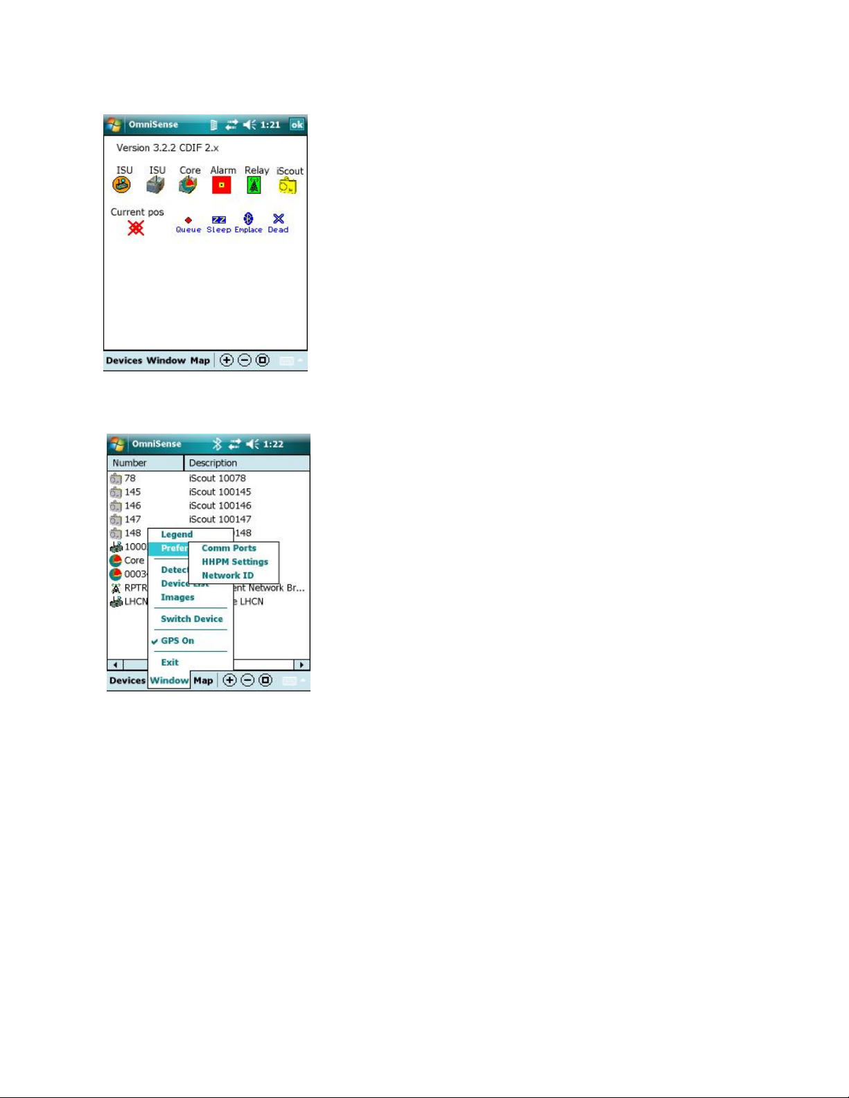
Figure 5-17: Legend Screen
Figure 5-18: Preferences Menu
5.4.1 Window Menu: Legend
The HHPM Legend Screen (Figure 5-17) provides a key to
sensor icons displayed on the Sensor Map. This screen can be
accessed by selecting the Legend option on the Window
menu. To close the Legend Screen, tap on the OK button at
the top right of the screen.
5.4.2 Window Menu: Preferences
Selecting the Preferences option displays the Preferences
menu (Figure 5-18).
iScout® System User’s Manual 37
© McQ Inc 2008

Figure 5-19: Comms Port Window
Preferences: Comm Ports
The HHPM Comms Port Window (Figure 5-19) allows you
to set the communications method and port settings.
Bluetooth (Device): Use this option to communicate with the
sensor directly via Bluetooth. This option is not available with
the iScout® System.
Bluetooth (WMR): Use this option to communicate with the
sensor using Bluetooth via a Wireless Mobile Relay. Set the
Comm Port at 8 or 9.
Serial Cable: Use this option when plugging the HHPM into
a sensor.
GPS: Set the GPS Comm Port to COM2.
Preferences: HHPM Settings
Figure 5-20: HHPM Settings Preferences
The HHPM Setting Preferences window (Figure 5-20) allows the user to configure a variety of
options. This configuration will be saved by the HHPM until reconfigured by the user. There
are three tabs: one for Display preferences, one for Map preferences and the other for Unit
preferences. The options on each tab are described below.
Display Tab
Display All Statuses
If checked the HHPM will automatically display all status messages received from any sensor. If
unchecked only the requested status messages will be displayed.
Display All Images
iScout® System User’s Manual 38
© McQ Inc 2008

If checked the HHPM will automatically display all images received from any sensor. If
unchecked only the requested images will be displayed.
Display All Configurations
If checked the HHPM will automatically display all configurations received from any sensor. If
unchecked only the requested configurations will be displayed.
Audio When Message Received
If this box is checked, all incoming messages prompt the HHPM audibly alert the user. If the
box is unchecked there will be no audible alert.
NOTE: This setting does not affect audible detection alerts.
iScout® System User’s Manual 39
© McQ Inc 2008

Display Detections
If this box is checked, a detection bubble containing data about the detection will be displayed
any time a sensor makes a detection. If the box is unchecked the detection bubble will not be
displayed but the detection data will still be added to the Detection List.
HHPM Time is Valid
By checking this box you are confirming that the HHPM’s time corresponds to that of an
accurate time source. If the box is checked, the HHPM will send the time with all
configurations. This box is always unchecked when you start the HHPM regardless of how it
was set during the previous session.
Notify on Configuration Received
If this box is checked the user will be alerted if a new configuration is received while the current
configuration is being edited. If the box is not checked the user will not be alerted.
Map Tab
Display Location on Map
Displays the location in the selected units in a status bar at the bottom of the map. This status
bar will not be present if the box is unchecked but the Current Location Icon will appear on the
map.
Pan Map to Location
If this box is checked the map will be displayed so that the Current Location Icon will be in the
center.
Pan Map to Detection
If this box is checked the map will automatically pan to any sensor that makes a detection. The
map will not pan if the box is unchecked.
Display Device Label
When checked this option displays the device number on map display. If unchecked, the number
will not be displayed.
iScout® System User’s Manual 40
© McQ Inc 2008

Units Tab
GPS Units
Four options are given. The first option displays the GPS
reading in decimal degrees. The second, in degrees, minutes
and hemisphere. The third as Universal Transverse Mercater.
The fourth as MGRS (Military Grid Reference System) as in
Figure 5-21. The GPS data in the units of your choice will be
displayed on the Status Bar, in the Location Tab and in the
Device List.
Figure 5-21: MGRS Display
Update HHPM to GPS Time
If this box is checked the HHPM clock will be automatically updated to reflect the GPS time. If
the box is unchecked the time will not be updated.
Distance Units
Select Feet or Meters. The unit you choose will be used on the Status Bar, the Location Tab
and will be displayed on the map when the HHPM is in Measure Mode.
5.4.3 Window Menu: Detections
The Detections option displays a list of detections received from the sensors. Each detection
entry includes Date, Time, Device Number and Detection by type. If you hold the stylus on the
screen you will display the Clear All option. Continuing to hold the stylus on the screen will
clear all detections from the list.
iScout® System User’s Manual 41
© McQ Inc 2008

5.4.4 Window Menu: Device List
Figure 5-22: Device List Left and Right Screens
The Device List option displays the Device List (Figure 5-22), a list of the devices in the current
sensor field. Each device is described by the following characteristics: number, description, unit
ID, mode, Link Quality Indicator (LQI), latitude and longitude.
The data in the Device List may be arranged in ascending order with respect to number,
description or label. To sort, tap on the desired heading. An item can be selected from the
Device List by tapping on it. It can then be commanded and configured using the Device menu.
5.4.5 Window Menu: Images
The iScout® is not configured with this option so a blank
screen will be displayed (Figure 5-23).
5.4.6 Window Menu: Switch Sensor
This option is available in local comms mode (Bluetooth). It
allows you to switch to a different sensor.
5.4.7 Window Menu: GPS On
If this option is checked, the HHPM GPS capabilities are
turned on. Unchecking the option turns them off.
5.4.8 Window Menu: Exit
This option closes the HHPM program. Use the Exit option
to shut down the HHPM.
Figure 5-23: Current Image Screen
iScout® System User’s Manual 42
© McQ Inc 2008

5.5 Devices Menu
Selecting the Devices button generates the Devices menu
(Figure 5-24). The options that are available on this menu
depend on what type of device you are working with.
Figure 5-24: Devices Menu
5.5.1 Devices Menu: Discover Devices
This option sends a configuration request to any devices that the HHPM can communicate with.
Any devices that respond will appear in the Device List.
5.5.2 Devices Menu: Request Status
This option displays the Device Status window (Figure 5-25). This window displays the current
status of the device that you currently have highlighted on the Sensor Map or in the Device List.
The Time and Date of the status message is displayed at the top right of the window.
Device Name
This is the user-assigned name of the highlighted device.
Status Time
The date and time that the displayed status data was taken.
On Time
This time represents the length of time that the device has been
continuously powered on without being reset.
Battery
This number represents the battery voltage at the time of the
Figure 5-25: Device Status Window
status message. Acceptable battery voltage falls within the
range of 2.8 to 3.4 VDC.
BITE Failures
Displays the results of the last GPS, Local Communications and Extended Communications
tests.
iScout® System User’s Manual 43
© McQ Inc 2008

Mode
The current sensor mode.
Report Interval
This number shows how often the device sends a status report. You have to configure the sensor
to modify this value.
Communication Statuses
The Communications Status Table on the Device Status
window (Figure 5-26) shows the metrics of the
communications quality between the device that you currently
have selected and up to five devices that the currently selected
device has heard from.
The first column lists the Device that has communicated with
your selected sensor.
The second column shows the Link Quality Indicator (LQI).
This indicator is represented as 0 to 5 bars.
The third column (Rx) shows the number of packets correctly
received from the Device ID listed to your currently selected
Figure 5-26: Device Status Window
| Communications Status Table
successful transmissions versus the number of transmission attempts between the two devices.
5.5.3 Devices Menu: Command Image
The Command Image option is not available on this system at this time.
device.
The final column (Succ/Att) represents the number of
iScout® System User’s Manual 44
© McQ Inc 2008

5.5.4 Devices Menu: Command Switch
Command Switch option display the Command Switch
screen (Figure 5-27) and allows you to set the output switch
state. The state that is shown on the Command Switch
screen is the opposite of the currently known switch state.
To change the switch state, tap the Cmd Switch button and
then the OK button. See Section 4.2 for more information
about Switch Closure capabilities.
Figure 5-27: Command Switch Screen
iScout® System User’s Manual 45
© McQ Inc 2008

5.5.5 Devices Menu: Configure Device
Selecting this option commands the device to report its current configuration. The configuration
will be displayed in screens identical to those described in Section 0 below.
Location
The Number and Description are assigned to the device by
the user and can be modified on the Location Panel (Figure
5-28). Both fields accept alphanumeric data
The Latitude, Longitude and Altitude of the device can be
changed by typing in a new value or by using GPS readings.
To use GPS, position the HHPM so the current Latitude,
Longitude and Altitude values reflect the location of the
device then tap the Mark button. The GPS fix will be placed
in the Latitude, Longitude and Altitude boxes. The Send
button will automatically be checked so that the location is
sent to the sensor. If you do not want to send the GPS location
to the sensor, uncheck the Send box.
Figure 5-28: HHPM Location Panel
If the HHPM does not have a GPS fix the Mark button will be
greyed out (Figure 5-29).
Figure 5-29: Mark Button | No
GPS Fix
iScout® System User’s Manual 46
© McQ Inc 2008

Figure 5-30: HHPM Location Panel
with GPS Off
If GPS is currently turned off, a message will be displayed
under Current Position (Figure 5-30). Use the GPS On
button to turn GPS on.
Figure 5-31: HHPM Comms Panel
Configuring Comms
The Comms Panel (Figure 5-31) allows you to set
communications parameters.
Report Interval
The slider bar at the bottom of the screen allows the user to
change the time interval between device status reports
Network ID
Set the local communications network channel to the same
channel as the LHCN that the device will use.
iScout® System User’s Manual 47
© McQ Inc 2008

Transducers
Upon set up in the field, the device automatically detects all
transducers that it has connected and sends this information to
the HHPM when requested. The data appears on the HHPM
Transducers Panel (Figure 5-32) but is not configurable.
Figure 5-32: HHPM Transducers
Panel
Algorithms
You can configure the algorithms used by the device to analyze
detection data. Figure 5-33 shows the HHPM Algorithms
Panel. Some algorithms allow you to set a sensitivity level (=
or = =), others are simply on or off. Det Switch and Tamper
algorithms have drop down menus described below. Select the
desired option for the algorithm using the drop down menu.
Det Switch represents the algorithms for the optional input
switch to the sensor. You are presented with four algorithm
options:
1. Off: disables the switch algorithm.
2. Change: commands the sensor to send a detection
upon a change in switch state.
Figure 5-33: HHPM Algorithms
Panel
If you select the Tamper algorithm, you will be asked to choose a tamper response from the
following list:
1. Off: the device will not report when tampered.
2. Report Tamper Only: the device will report the tamper detection to the SADU.
3. Report and Kill Sensor: the device will report the tamper detection to the SADU
and then will be killed. This means that it must be returned to McQ Inc. for
reconfiguration.
3. Open: commands the sensor to send a detection if the
external switch has opened.
4. Close: commands the sensor to send a detection if the
external switch has closed.
iScout® System User’s Manual 48
© McQ Inc 2008

Sleep
The Sleep Panel (Figure 5-34) allows you to set Sleep Mode
intervals for the selected device.
First, specify the day for the Sleep Interval using the Day
menu.
Next, specify the endpoints of the Sleep Mode period for that
day by setting the Start Time (in GMT) and the Duration
(in hours and minutes) of the Sleep Mode period. Tap the
Add button to add the new Sleep Mode interval to the
device’s sleep schedule. Repeat the process to create another
interval on the same day or on a new day.
Figure 5-34: HHPM Sleep Panel
The Sleep Schedule will repeat weekly as configured by the user.
NOTE: The device will remain in Sleep Mode as configured by the user. It cannot be
awakened ahead of schedule except by reconnecting the battery pack in the field.
5.5.6 Devices Menu: Configure PTZ
The iScout® system is not configured for this option at this time.
5.5.7 Devices Menu: Set Operational
Figure 5-35: Begin Operation
Confirmation
To delete a particular sleep interval from the device’s sleep
schedule, select it and tap the Delete button.
Use the Set Operational option (Figure 5-35) to switch the
sensor from Emplacement Mode to Normal Mode. This
action will begin sensor operation with the characteristics
that you have configured.
iScout® System User’s Manual 49
© McQ Inc 2008

NOTE: If you forget to switch the sensor mode, the sensor will switch automatically after
10 minutes.
5.5.8 Devices Menu: Switch CDIF
Use this option to switch to a different version of Common
Data Interchange Format (CDIF). This action is necessary in
order to communicate with older sensors.
Figure 5-36: Switch CDIF Message
iScout® System User’s Manual 50
© McQ Inc 2008

6 Technical Support
6.1 Maintenance
In general, only minor maintenance will be routinely required on iScout components. Typical
field maintenance will include changing the batteries and cleaning the PIR lens. There are no
user serviceable parts within the electronics. When service on these units is required, these units
should be returned to McQ for repair and/or replacement. Training will be provided to allow
personnel to use the Built In Test Equipment and unit diagnostics to determine when a system
requires maintenance.
6.2 Training
McQ will provide both introductory and advanced level training on the iScout system and its
components when the system is delivered. For some customers, McQ trains government trainers
who then train the sensor installation and operation teams. This training will enable the users to
successfully deploy and operate all of the components of the system. Additional training can be
offered under a support contract at times and at a frequency deemed necessary by the customer.
In general, the iScout system is designed to be as intuitive as possible and to require only
minimal training. All customers are provided with this user’s manual providing an overview of
system operation and the basic steps necessary to operate and use the system.
6.3 Installation
In general, trained users will not require factory assistance in installations. However, when
assistance is desired for either technical or operational reasons, McQ can provide such assistance
under a support contract with virtually any type of field installation. This manual includes an
iScout Sensor Installation Guide. This guide gives detailed instructions on setting up a system.
6.4 Configuration Management and Program Support
As the number of iScout sensors and other systems expands, the customer may need additional
support in tracking and recording the configuration and distribution of all iScout assets. McQ can
assist the customer under a support contract by keeping a detailed record of asset status and
distribution. This information can be available along with additional support to the customer for
all iScout system technical and operational issues.
6.5 Contact Information
Technical Support
McQ will provide technical support during normal business hours 8:00 am to 5:00 pm EST) via
the company phone (540.373.2374/866.373.2374) and via E-mail (support@mcqinc.com). After
hours the phone will be answered by a service and the user needs to identify “iScout Support” to
the service representative to ensure the user is routed to the correct McQ support person. The
service representative will have the user provide a telephone number for McQ technical support
staff to call. The user needs to identify the urgency of the support response.
Warranty Support
iScout® System User’s Manual 51
© McQ Inc 2008

When returning iScout units under warranty, the user will call the technical support number
shown above or send an E-mail describing what warranty support is needed. The McQ
representative will give the user specific handling instructions.
iScout® System User’s Manual 52
© McQ Inc 2008

7 End Users License Agreement
CAREFULLY READ THE FOLLOWING LICENSE AGREEMENT. BY USING THIS
EQUIPMENT AND/OR SOFTWARE IN ANY WAY, YOU AND YOUR COMPANY
ACKNOWLEDGE THAT YOU HAVE READ THIS AGREEMENT, UNDERSTAND IT,
AND ARE AGREEING TO BE BOUND BY THE TERMS AND CONDITIONS OF THIS
AGREEMENT.
IF YOU DO NOT CONSENT TO THIS AGREEMENT, THEN DO NOT USE THE
EQUIPMENT, SOFTWARE, OR MANUAL. PROMPTLY CONTACT MCQ INC.
1. LICENSE GRANT
The computer programs and algorithms, and any portion thereof, (or "Software") and the related
explanatory written materials (or "Documentation"), whether provided independently or loaded
onto processors, equipment, sensors, or other media, or components (or “equipment”) delivered
by McQ Inc, is licensed – not sold – to you by McQ Inc (or “McQ”). Subject to the terms and
conditions of this Agreement, McQ hereby grants to you a nonexclusive license to use one copy
of the Software on any single computer, such that the Software is in use on only one computer
operated by only one person at any time. The Software is "in use" on a computer when it is
loaded or installed into the temporary or permanent memory of a computer or other storage
device or media. "You" or “you” means the person, company, or other entity that is being
licensed to use the Software or Documentation. You may own the computer or the media on
which the Software is provided, but the Software is owned and copyrighted by McQ.
In the event that you have purchased from McQ any upgrades, modifications, updates, additions,
or other copies of the Software, then “Software” shall be deemed to include such upgrades,
modifications, updates, additions, or other copies.
2. TITLE
All rights not specifically granted to you in this Agreement are reserved by McQ. Apart from
the rights enumerated herein, this Agreement does not grant you any right to engage in any other
activity with the Software, to enjoy any ownership right, title, or interest, nor to place any
security interest or other interest in any intellectual property relating to the Software or the
Documentation. McQ reserves all right, title, and ownership interest to the Software and
Documentation, and all rights not expressly granted to you in this Agreement.
3. ARCHIVAL OR BACKUP COPIES
You may either: (a) make one copy of the Software, solely for backup or archival purposes; or (b) make one copy of
the Software onto a single hard disk, provided you keep the original solely for backup or archival purposes.
4. THINGS YOU MAY NOT DO
The Software and Documentation contain trade secrets or other proprietary information of McQ, and are protected
by state and federal trade secret laws. In addition, the Software is protected by United States copyright laws and
international treaties. You agree to respect all applicable copyright and trade secret laws.
iScout® System User’s Manual 53
© McQ Inc 2008

You agree that you shall not, by way of example and not limitation:
(a) copy the Documentation;
(b) copy the Software, except as permitted in Section 3;
(c) create derivative works, modify, alter, transform, translate, tamper, or adapt the Software or Documentation, or
merge the Software into another program;
(d) reverse engineer, disassemble, decompile, or make any attempt to discover or gain access to the source code of
the Software;
(e) place the Software onto a processor or server so that it is accessible to any third party, or any public network,
such as the Internet;
(f) sublicense, rent, lease, or lend any portion of the Software or Documentation; and
(g) remove, obliterate, or cancel from view any patent, copyright, trademark, or confidentiality
notice or legend appearing in connection with the Software, its media, the Documentation or
output generated by the Software.
You agree to transfer to McQ all intellectual property and ownership rights for any version
created from the unauthorized modification or adaptation of this Software, including versions
created from the translation and/or reverse engineering of the Software
5. TRANSFERS
As noted above, you may not sublicense the Software. You may, however, transfer or assign ALL of your rights to
use the Software and Documentation to one (and only one) other person or legal entity, provided that they agree to
all the terms and conditions of this Agreement, and that you transfer to such person a copy of this Agreement, the
Software and Documentation (including any backup copy made under Section 3), and all updates or prior versions.
If you so transfer the Software, then you agree to retain no copies of the Software or
Documentation, including copies stored on any computer or media.
6. LIMITED WARRANTY
McQ warrants that for a period of one (1) year after delivery of this copy of the Software to you the physical media,
if any, on which your copy of the Software is distributed will be free from defects in materials and workmanship
under normal use, and during that one (1) year the Software will perform in substantial accordance with the
Documentation. Notwithstanding the foregoing, this Agreement makes no representation or warranty concerning
any equipment or any other deliverable or performance of McQ. The foregoing express, limited warranty is in lieu
of all other warranties.
THE SOFTWARE AND SUPPORTING DOCUMENTATION IS PROVIDED "AS IS" WITHOUT ANY OTHER
WARRANTY OF ANY KIND, EITHER EXPRESSED OR IMPLIED. McQ DISCLAIMS ANY AND ALL
OTHER WARRANTIES, REPRESENTATIONS, OR CONDITIONS, EXPRESS, IMPLIED, OR STATUTORY,
RELATING TO THE SOFTWARE AND DOCUMENTATION, INCLUDING ANY IMPLIED WARRANTY OF
TITLE, NON-INFRINGEMENT OF THIRD PARTY RIGHTS, MERCHANTABILITY, OR FITNESS FOR A
PARTICULAR PURPOSE. McQ DOES NOT WARRANT THAT THE FUNCTIONS CONTAINED IN THIS
SOFTWARE WILL MEET YOUR REQUIREMENTS OR THAT THE OPERATION OF THE SOFTWARE
WILL BE UNINTERRUPTED OR ERROR FREE. IN ADDITION, McQ DISCLAIMS ANY AND ALL
WARRANTIES OR REPRESENTATIONS TO ANY PERSON OTHER THAN YOU WITH RESPECT TO THE
SOFTWARE.
No employee, agent, dealer, or distributor of McQ is authorized to modify this limited warranty,
or to make any additional warranties.
iScout® System User’s Manual 54
© McQ Inc 2008

SOME STATES AND/OR COUNTRIES DO NOT ALLOW THE EXCLUSION OF IMPLIED
WARRANTIES, SO THE ABOVE EXCLUSION MAY NOT APPLY TO YOU. THIS
WARRANTY GIVES YOU SPECIFIC LEGAL RIGHTS, AND YOU MAY ALSO HAVE
THE LIABILITY LIMITATIONS IN THIS ARTICLE SHALL APPLY REGARDLESS OF WHETHER (A) McQ
HAS BEEN ADVISED OF THE POSSIBILITY OF THE CORRESPONDING LIABILITY, (B) THE SERVICES
WERE INTENDED TO PREVENT THE EVENTS THAT GAVE RISE TO THE CLAIMED LIABILITY, OR (C)
THE CLAIMED LIABILITY IS BASED ON BREACH OF CONTRACT OR WARRANTY, NEGLIGENCE
(SOLE OR CONCURRENT, ACTIVE OR PASSIVE), STRICT LIABILITY, FAILURE OF ESSENTIAL
PURPOSE OR ANY OTHER LEGAL OR EQUITABLE THEORY.
7. LIMITED REMEDY
McQ’s entire liability and your exclusive remedy shall be the replacement of any diskette(s) or other media not
meeting our Limited Warranty, which is returned to McQ or to an authorized Dealer or Distributor with a copy of
your receipt.
ASIDE FROM THE FOREGOING, NEITHER McQ NOR ITS CONTRACTORS SHALL HAVE ANY
LIABILITY TO YOU OR ANY OTHER PERSON OR ENTITY FOR ANY DAMAGES ARISING FROM THIS
AGREEMENT OR RELATED TO THE SOFTWARE, INCLUDING WITHOUT LIMITATION ANY DIRECT,
INDIRECT, INCIDENTAL, SPECIAL, PUNITIVE OR CONSEQUENTIAL DAMAGES, INCLUDING, BUT
NOT LIMITED TO, LOSS OF REVENUE OR PROFIT, LOSS OF OR DAMAGE TO DATA OR OTHER
COMMERCIAL OR ECONOMIC LOSS, EVEN IF McQ HAS BEEN ADVISED OF THE POSSIBILITY OF
SUCH DAMAGES, OR THEY ARE FORESEEABLE. SPECIFICALLY, McQ IS NOT RESPONSIBLE FOR
ANY COSTS INCLUDING, BUT NOT LIMITED TO THOSE INCURRED AS A RESULT OF LOST PROFITS
OR REVENUE, LOSS OF USE OF THE SOFTWARE OR OTHER COMPUTER PROGRAMS LOSS OR
DAMAGES, THE COST OF RECOVERING SUCH SOFTWARE OR COMPUTER PROGRAMS OR DATA,
THE COST OF ANY SUBSTITUTE PROGRAM, CLAIMS BY THIRD PARTIES, OR FOR OTHER SIMILAR
COSTS.
THE LIMITATIONS IN THIS SECTION SHALL APPLY WHETHER OR NOT THE ALLEGED BREACH OR
DEFAULT IS A BREACH OF A FUNDAMENTAL CONDITION OR TERM OR FUNDAMENTAL BREACH.
SOME JURISDICTIONS DO NOT ALLOW THE EXCLUSION OR LIMITATION OF LIABILITY FOR
CONSEQUENTIAL OR INCIDENTAL DAMAGES, SO THESE LIMITATIONS MAY NOT APPLY TO YOU.
THE LIMITED WARRANTY, LIMITED REMEDIES AND LIMITED LIABILITIES ARE FUNDAMENTAL
ELEMENTS OF THE BASIS OF THE BARGAIN BETWEEN McQ AND YOU. McQ WOULD NOT BE ABLE
TO PROVIDE THE SOFTWARE WITHOUT SUCH LIMITATIONS.
8. TERM AND TERMINATION
This Agreement is effective until terminated. You may terminate this license at any time by destroying all copies of
the Software and related Documentation. IN THE EVENT THAT YOU FAIL TO COMPLY WITH ANY TERM
OR CONDITION OF THIS AGREEMENT, THEN THIS AGREEMENT WILL AUTOMATICALLY
TERMINATE WITHOUT NOTICE FROM McQ OR ANY JUDICIAL RESOLUTION. When McQ learns of any
such non-compliance, McQ may confirm such automatic termination by written notice to you.
The requirements and provisions of Sections 4, 6, 7, 8, 9, and 10 of this Agreement shall survive
termination.
You hereby agree that on termination of this Agreement, regardless of the reason, You will either destroy or return
to McQ all copies of the Software and Documentation in your possession. You agree to stop all use of the Software
and Documentation upon termination of this Agreement.
iScout® System User’s Manual 55
© McQ Inc 2008

9. CONFIDENTIALITY
The Software, even though provided to you in object code form, inherently contains source code, trade secrets, and
proprietary know-how (“Confidential Information”) that belong to McQ, and it is being made available to you in
strict confidence. ANY UNAUTHORIZED USE OR DISCLOSURE OF THE SOFTWARE, OR OF ITS
ALGORITHMS, PROTOCOLS, OR INTERFACES MAY BE ACTIONABLE AS A VIOLATION OF McQ’s
TRADE SECRET RIGHTS.
Without prejudice to any and all prohibitions against reverse engineering or de-compiling the Software, you
acknowledge and agree that maintaining the confidentiality of Confidential Information is vital to the legitimate
business interests of McQ. You shall not at anytime, whether during the Term of this Agreement or thereafter,
disclose to any person or use any Confidential Information, or permit any person to examine and/or make copies of
any media which contain or were derived from Confidential Information, whether prepared by the You or otherwise,
without the prior written permission of McQ. You shall take all reasonable precautions to prevent any other person
or entity from acquiring, using or divulging Confidential Information anytime, unless McQ expressly permits in
writing the disclosure of the Confidential Information. In the event of the loss, disclosure or theft of any item
containing such information, You shall promptly notify McQ in writing of such event describing the item and its
contents. Upon request by McQ, and in any event immediately without the necessity of a request upon termination
or expiration of this Agreement, You shall turn over to McQ all Confidential Information in your possession or
under your control. The Parties agree that the Software shall be deemed a trade secret and Confidential Information
of the McQ. Any trade secret hereunder shall also be entitled to all of the protections and benefits under state law,
18 U.S.C. § 1831 et seq., and any other applicable law.
10. U.S. GOVERNMENT – UNLIMITED RIGHTS
This Software has previously been delivered and licensed to the U.S. Government with “Unlimited Rights.” U.S.
Government customers are therefore governed by the terms and conditions delineated under "Unlimited Rights" in
FAR 52.227-14 “Rights in Data – General,” DFAR 252.227-7013 “Rights in Technical Data - Noncommercial
Items,” and/or DFAR 252.227-7014 “Rights in Noncommercial Computer Software and Noncommercial Computer
Software Documentation,” as applicable. If this Agreement fails to meet the Government's minimum needs, or is
inconsistent with Federal procurement law, then the Government agrees to notify McQ in writing. The
manufacturer of the Software is McQ Inc, 1551 Forbes Street, Fredericksburg, VA 22405 USA.
11. MISCELLANEOUS
(a) This Agreement shall be governed and construed by the laws of the Commonwealth of Virginia. Any legal action
between the parties shall be initiated and conducted exclusively in the federal and state courts located within
Alexandria, Virginia, United States of America, and in any such legal action, the parties hereby consent to the
exclusive jurisdiction of, and venue in, such courts. In the event of litigation between you and McQ concerning the
Software or Documentation, the prevailing party in the litigation will be entitled to recover reasonable attorneys’
fees and expenses from the other party.
(b) You agree that the Software and Documentation will not be shipped, transferred, or exported outside of the
United States in any manner prohibited by the United States Export Administration Act or any other export laws,
restrictions, or regulations.
(c) If, for any reason, a court of competent jurisdiction finds any provision of this license, or portion thereof, to be
unenforceable, that provision shall be enforced to the maximum extent permissible so as to effect the intent of the
parties, and the remainder of this license shall continue in full force and effect.
(d) No delay on the part of McQ in exercising any right or remedy under this Agreement shall operate as a waiver
thereof, nor shall any single or partial exercise of any right or remedy under this Agreement preclude any other or
further exercise of such right or remedy. Failure of McQ to enforce compliance with any term, provision or
condition of this Agreement shall not constitute a waiver of such term or condition.
(e) This Agreement constitutes the entire agreement between you and McQ relating to the subject matter, and
supersedes all other agreements, written or oral, relating to the subject matter. This Agreement may not be
amended, modified or altered in any respect whatsoever except in writing designated as such and signed by both
parties.
(f) Wherever possible, each provision of this Agreement shall be interpreted in such a manner as to be effective and
iScout® System User’s Manual 56
© McQ Inc 2008

valid under applicable law. However, if any provision of this Agreement shall be prohibited by or invalid under
applicable law, such provision shall be ineffective only to the extent of such prohibition or invalidity without
invalidating the remainder of such provision or the remaining provisions of this Agreement. In such an event, then
the parties agree to authorize the court to re-write that provision, to the extent of such un-enforceability, so as to
preserve and/or effect the intent of the parties as described herein, to the extent permitted by law.
(g) The parties agree that monetary damages alone shall be an inadequate remedy in the event that you breach
Sections 4 or 9, and that any such breach shall cause McQ irreparable injury and damage. Accordingly, McQ shall
be entitled, without waiving any additional rights or remedies otherwise available to McQ at law or in equity or by
statute, to injunctive and other equitable relief in the event of a breach, or in the event of intended or threatened
breach, by you.
(h) Titles contained in this Agreement are inserted only as a matter of convenience and in no way modify, define,
amplify, limit, or extend the scope or intent of this Agreement, or any provision thereof
(i) Should you have any questions concerning this Agreement, please write: McQ Inc, 1551 Forbes Street,
Fredericksburg, VA 22405 USA.
iScout® System User’s Manual 57
© McQ Inc 2008

8 APPENDIX A FCC (United States) Certification
General Statements
The iScout® sensor and the WMR and their enclosed modularly approved radios comply with
Part 15 of the FCC Rules. Operation is subject to the following two conditions: (1) This device
may not cause harmful interference, and (2) this device must accept any interference received,
including interference that may cause undesired operation.
Device Classification
NOTE: The iScout® sensor and WMR have been tested and found to comply with the limits for
a Class A digital device, pursuant to part 15 of the FCC Rules. These limits are designed to
provide reasonable protection against harmful interference when the equipment is operated in a
commercial environment. This equipment generates, uses, and can radiate radio frequency
energy and, if not installed and used in accordance with the instruction manual, may cause
harmful interference to radio communications. Operation of this equipment in a residential area
is likely to cause harmful interference in which case the user will be required to correct the
interference at his own expense.
Modifications FCC part 15.21
Changes or modifications to the iScout® sensor or WMR which are not expressly
approved by McQ Inc. will void the user's authority to operate the equipment, per FCC
section 15.21 of the FCC guidelines.
FCC Approved ANTENNAS FCC Part 15.204(c)
Sensor Antennas
This iScout® sensor shall only be operated with the FCC approved antennas listed in Table 2.
The antennas listed in Table 2 can be obtained directly from McQ. Antennas not supplied by
McQ must be tested to comply with FCC Section 15.203 (unique antenna connectors) and
Section 15.247 (emissions).
Table 2: FCC Approved iScout® Sensor Antennas
Part Number
IS 8110 Half-wave w/ 8' pig tail RPSMA 2.3 dBi (excluding cable loss) Fixed/Mobile
IS 8111 Half-wave RPSMA 2 dBi Mobile
Type Connector
Gain Application
WMR Antennas
This WMR shall only be operated with the FCC approved antennas listed in Table 3. The
antennas listed in Table 3 can be obtained directly from McQ. Antennas not listed in Table 3
must be tested to comply with FCC Section 15.203 (unique antenna connectors) and Section
15.247 (emissions).
Table 3: FCC Approved WMR Antennas
Part Number
IS 8112 Mag. Mount Whip w/ 10' pig tail RPSMA 5 dBi (excluding cable loss) Fixed/Mobile
IS 8110 Half-wave w/ 8' pig tail RPSMA 2.3 dBi (excluding cable loss) Fixed/Mobile
Type Connector
Gain Application
iScout® System User’s Manual 58
© McQ Inc 2008

RF Exposure Cautionary Notice
WARNING: This equipment is approved only for mobile and base station transmitting devices.
Antenna(s) used for the iScout® sensor must be installed to provide a separation distance of at
least 30 cm from all persons and must not be co-located or operating in conjunction with any
other antenna or transmitter.
Antenna(s) used for the WMR must be installed to provide a separation distance of at least 20 cm
from all persons and must not be co-located or operating in conjunction with any other antenna
or transmitter.
iScout® System User’s Manual 59
© McQ Inc 2008
 Loading...