

McNeilus Standard Rear Loader, XC Rear Loader, HD Rear Loader, XXC Rear Loader, Rear Loader with Tag Axle Operator's Manual

© 2008 McNeilus Truck and Manufacturing, Inc.
OPERATOR’S MANUAL
Standard Rear Loader
Includes the Following Models:
• Standard Rear Loader
• Rear Loader with Tag Axle
• XC Rear Loader
• XXC Rear Loader
• HD Rear Loader
• HD Rear Loader (3.5 YD Hopper)
Publication No. 1432584
Rev. 0918

Disclaimer:
This manual must not be used to repair your vehicle. Repair information is available by calling McNeilus Customer Service at
(888) 686-7278.
The information in this Operator
’s Manual will be your guide to operation and operator maintenance for this equipment.
A
published.
product improvement policy
service, or maintenance improvement.
www
No part of this publication may be reproduced by any means - graphic, electronic, or mechanical, including photocopying,
recording, taping, or information storage and retrieval systems for any use or purpose - without the written permission of McN
Tr
For assistance in ordering OSHA Publications, contact:
For assistance in ordering the Waste Collection
V
National W
1550 Crystal Drive
A
T
ll information, illustrations, and specifications in this manual are based on the information available at the time this manual was
The illustrations used in this manual are intended as representative reference views only. Because of our continuous
, we may modify information, illustrations, and/or specifications to explain and/or exemplify a product,
We reserve the right to make any change at any time without notice. Go to
.streetsmartparts.com for current information.
uck and Manufacturing, Inc.
ehicle Safety Guide, contact:
aste and Recycling Association
• Suite 804
rlington, VA 22202
elephone: 800-424-2869 • Fax: 202-966-4824
Rear Loader
U.S. Department of Labor/OSHA
OSHA Publications
P.O. Box 37535
Washington, D.C. 20210
Telephone: 202-693-1888 • Fax: 202-693-2498
© 2008 McNeilus Truck and Manufacturing, Inc.
eilus

1.0 Identication Plate
A McNeilus Truck and Manufacturing, Inc. identication plate
(Figure 1, Item 1) is located on the left front side of the refuse
vehicle body. The identication plate contains the Model
Number and Serial Number of your refuse vehicle.
To serve you better, please ll out the following information
and have it ready when calling McNeilus Truck and
Manufacturing, Inc. for parts or product information:
Date of Purchase: __________________________________
Foreword
McNeilus Branch: __________________________________
Model Number: ____________________________________
Serial Number: ____________________________________
VIN*: _____________________________________________
*Refer to chassis manufacturer literature for location.
© 2008 McNeilus Truck and Manufacturing, Inc.
1
Figure 1
Rear Loader

Foreword
45
6
2
2.0 Complete Vehicle Decal
The complete vehicle decal (Figure 2) details the axle load
and tire ratings as the vehicle left the McNeilus production line.
This decal is located inside the cab and may be placed on the
driver’s door, doorjamb, or the seat riser.
The complete vehicle decal (Figure 2, Item 1) includes the
following information:
This decal includes information such as the Maximum rated
weight per axle (Item 2), Gross Vehicle Weight (Item 3),
Chassis manufacturer (Item 4), Chassis build date (Item 5),
Vehicle (chassis) ID number (Item 6), Tire and rim size and
tire pressure specications (Item 7), and the Refuse vehicle
system build date (Item 8).
3.0 Purpose of Manual
This Operator Manual provides operation and operator
maintenance instructions for the Standard Rear Loader refuse
collection system manufactured by McNeilus Truck and
Manufacturing, Inc.
The information in this operator manual will be your guide to
operation and operator maintenance for this equipment.
Keep this manual with the vehicle at all times.
3
S/O #: nnnnnn Body Mount Date: MM/D/YYYY Data Plate ID: nnnnn
MFD. BY McNEILUS TRUCK & MFG. INC
GVWR
FR. GAWR
1ST GAWR
2ND GAWR
3RD GAWR
4TH GAWR
REAR GAWR
CONFORMITY OF THE CHASSIS-CAB TO FEDERAL MOTOR VEHICLE SAFETY STANDARDS WHICH HAVE BEEN PREVIOUSLY FULLY
CERTIFIED BY THE INCOMPLETE VEHICLE MANUFACTURER OR BY THE INTERMEDIATE VEHICLE MANUFACTURER, HAS NOT BEEN
AFFECTED BY FINAL-STAGE MANUFACTURER, THE VEHICLE HAS BEEN COMPLETED IN ACCORDANCE WITH THE PRIOR
MANUFACTURER’S INSTRUCTIONS WHERE APPLICABLE. THIS VEHICLE CONFORMS TO ALL OTHER SAFETY STANDARDS IN EFFECT IN:
INCOMPLETE VEHICLE MFD. BY DATE
34,75576,620
LB KG
20,000
22,800
20,000
20,000
22,800
11,020
VEHICLE TYPE CLASSIFICATION
9,072
LB
LB
LB W/ TIRES ON RIMS @PSI COLD KPA
LB W/ TIRES ON RIMS @PSI COLD KPA
LB
LB
KG
10,342
KG
KG
KG
10,342
KG
4,999
KG
MFGR NAME
TRUCK
445/65R22.5
W/
W/
W/
W/
445/65R22.5
445/65R22.5
255/70R22.5
TIRES ON
TIRES ON
TIRES ON
TIRES ON
1
Figure 2
VEHICLE ID #
22.5 X 13.0
22.5 X 13.0
22.5 X 13.0
22.5 X 8.25
nnnnnnnnnnnnnnnnn
RIMS @
RIMS @
RIMS @
RIMS @
MM/D/YYYY
120
PSI COLD KPA
120
PSI COLD KPA
120
PSI COLD KPA
115
PSI COLD KPA
MO
YR
830
830
830
790
MMM
YYYY
7
8
Rear Loader
© 2008 McNeilus Truck and Manufacturing, Inc.

Foreword
NOTE
WARNING
The operator of this vehicle must be
properly licensed and trained to operate
this vehicle.
If you do not have the proper training and
licensing to operate this vehicle, you are
putting yourself and others at risk of
serious injury or death.
If you are uncertain how to operate this
Packer, inform your supervisor or contact
McNeilus Truck and Manufacturing, Inc.
at 888-686-7278.
This manual is limited to the operation and
light maintenance of the refuse collection
system only.
This manual does not include the operation
or maintenance of the chassis vehicle upon
which the refuse collection system is
mounted.
4.0 Scope
This manual provides information for use by the equipment
operator under the following headings:
1. Safety. Includes important safety information.
2. General. Includes equipment identication.
3. Operation. Includes control functionality and normal
equipment operation.
4. Preventive Maintenance. Includes basic preventive
maintenance information for the operator.
5. Troubleshooting. Includes basic troubleshooting
information for the operator.
To order a replacement manual or safety signs, call the
McNeilus parts and service number listed in the Foreword of
this manual.
© 2008 McNeilus Truck and Manufacturing, Inc.
Rear Loader

Foreword
Phone Number
888-686-7278
State City
CA
CT
FL
GA
IL
IN
MN
NY
Canada
Ontario and W
Quebec and Maritime Provinces 800-996-4937
5.0 Parts and Service
Contact your McNeilus Parts and Service branch locations
to order parts, receive service information, or for other
assistance.
Contact by phone or visit www.streetsmartparts.com.
We have factory owned parts and service centers near you.
Colton
East Granby
Tampa
Villa Rica
Sugar Grove
Bronx
State City
OH Cincinnati
OH Columbus
PA Morgantown
TX Houston
TX Hutchins
Fort Wayne
Dodge Center
UT West Valley City
WI Oshkosh
estern Provinces 800-265-1089
6.0 Corporate Headquarters
Contact McNeilus Truck and Manufacturing, Inc. directly at
our corporate headquarters at the following address, phone
number, and website.
McNeilus Truck and Manufacturing, Inc.
524 County Road 34 East
Dodge Center, MN 55927
Telephone: 507-374-6321
Corporate Website: www.mcneiluscompanies.com
Parts and Service Website: www.streetsmartparts.com
Rear Loader
© 2008 McNeilus Truck and Manufacturing, Inc.

Table of Contents
SAFETY
1.0 IMPORTANT SAFETY INFORMATION .............................................................................................................1
1.1 Battery Disconnect Switch .........................................................................................................................2
1.1.1 Battery Cable Disconnect ...............................................................................................................3
1.2 Safety Equipment ......................................................................................................................................3
1.3 Reporting Safety Defects ..........................................................................................................................3
2.0 SAFETY NOTICES ............................................................................................................................................4
3.0 PRODUCT SAFETY INFORMATION ................................................................................................................5
3.1 Safety ........................................................................................................................................................5
3.2 Cab Operation ...........................................................................................................................................7
3.3 Outside Operation ...................................................................................................................................10
3.4 Maintenance ............................................................................................................................................16
3.5 Hydraulics ................................................................................................................................................21
3.6 Electrical ..................................................................................................................................................27
4.0 SAFETY SIGNS ..............................................................................................................................................28
4.1 Safety Sign Locations ..............................................................................................................................30
4.1.1 Street Side Signs..........................................................................................................................30
4.1.2 Curb Side and Front Signs ...........................................................................................................31
4.1.3 Rear and Door Signs ....................................................................................................................32
© 2008 McNeilus Truck and Manufacturing, Inc.
I
Rear Loader

Table of Contents
GENERAL INFORMATION
1.0 EXTERIOR SYSTEMS ARRANGEMENT .......................................................................................................33
1.1 Street Side View ......................................................................................................................................33
1.2 Curb Side View ........................................................................................................................................34
1.3 T-Type Container Specications ..............................................................................................................35
1.3.1 Type T Container 3 yd3 or Less Capacity .....................................................................................35
1.3.2 Type T Container More Than 3 yd3 and Less Than 10 yd3 Capacity ............................................37
OPERATION
1.0 INSTRUMENTS AND CONTROLS ................................................................................................................39
1.1 Cab Controls ...........................................................................................................................................39
1.1.1 Rocker Switches...........................................................................................................................40
1.1.2 Indicator Lights .............................................................................................................................41
1.1.3 Fuse Panel ...................................................................................................................................42
1.2 Outside Rear Controls .............................................................................................................................43
1.3 Outside Front Controls ............................................................................................................................45
2.0 CONTROL FUNCTIONS .................................................................................................................................46
2.1 E-STOP (Emergency Stop) Function ......................................................................................................46
2.1.1 E-STOP Button In-Cab Control Box .............................................................................................47
2.2 Sweep Functions .....................................................................................................................................47
Rear Loader
II
© 2008 McNeilus Truck and Manufacturing, Inc.

Table of Contents
2.3 Slide Functions ........................................................................................................................................49
2.4 Turnbuckle and Optional Hydraulic Tailgate Lock Operation ...................................................................50
2.4.1 Trucks Without Tag Axle (Turnbuckle) ..........................................................................................50
2.4.2 Trucks With Tag Axle (Turnbuckle) ...............................................................................................51
2.4.3 Hydraulic Tailgate Locks (Optional) ..............................................................................................52
2.4.3.1 Unlock Tailgate (Hydraulic Locks) ..................................................................................52
2.4.3.2 Lock Tailgate (Hydraulic Locks) .....................................................................................53
2.5 Tailgate Functions ...................................................................................................................................53
2.6 Ejector Functions .....................................................................................................................................54
3.0 OPERATING PROCEDURES .........................................................................................................................55
3.1 Start-Up Procedure .................................................................................................................................56
3.2 Warm-Up Procedure ................................................................................................................................56
3.3 Traveling Procedure ................................................................................................................................57
3.4 Before Starting The Route .......................................................................................................................57
3.5 Refuse Loading Procedure ......................................................................................................................57
3.5.1 Manual Trash Pick-Up ..................................................................................................................57
3.5.2 Residential Cart Loading (Optional Cart Tipper) ..........................................................................58
3.5.3 Commercial Container Loading ....................................................................................................58
3.6 Refuse Packing Procedure ......................................................................................................................60
3.7 Refuse Ejector Procedure .......................................................................................................................61
© 2008 McNeilus Truck and Manufacturing, Inc.
III
Rear Loader

Table of Contents
3.8 End of Day Checks ..................................................................................................................................62
4.0 OPTIONAL EQUIPMENT ................................................................................................................................63
4.1 Residential Cart Tipper Panel ..................................................................................................................63
4.2 Container Lock ........................................................................................................................................64
4.3 Container Tipper ......................................................................................................................................65
4.4 Winch or Reeving Cylinder ......................................................................................................................66
4.5 Lateral Protection Device ........................................................................................................................68
4.6 Auxiliary Axle ...........................................................................................................................................70
4.6.1 Lowering the Pusher or Tag Axle ..................................................................................................71
4.6.2 Raising the Pusher or Tag Axle ....................................................................................................71
4.7 Water Tank ..............................................................................................................................................72
4.7.1 Water Tank Safety ........................................................................................................................72
4.7.2 Introduction...................................................................................................................................72
4.7.3 Daily Inspection ............................................................................................................................73
4.7.3.1 Tank Integrity ..................................................................................................................73
4.7.3.2 Pressure Regulator Valve ..............................................................................................73
4.7.3.3 Pressure Relief Valve .....................................................................................................74
4.7.4 Daily Operation.............................................................................................................................74
4.7.5 Vehicle Handling Characteristics ..................................................................................................74
4.7.6 Water Tank Sign Identication ......................................................................................................74
Rear Loader
IV
© 2008 McNeilus Truck and Manufacturing, Inc.

Table of Contents
4.7.7 Water Tank Operation...................................................................................................................75
4.7.7.1 Filling the Tank ...............................................................................................................75
4.7.7.2 Pressurizing the Water Tank ..........................................................................................76
4.7.7.3 Depressurizing the Water Tank ......................................................................................77
4.7.7.4 Draining the Water Tank .................................................................................................78
PREVENTIVE MAINTENANCE
1.0 PREVENTIVE MAINTENANCE.......................................................................................................................81
1.1 DOT Pre-Trip ...........................................................................................................................................81
2.0 PREVENTIVE MAINTENANCE INTERVALS ..................................................................................................81
3.0 DAILY PREVENTIVE MAINTENANCE CHECKS ...........................................................................................86
3.1 Hydraulic System ....................................................................................................................................86
3.1.1 Hydraulic Oil Level .......................................................................................................................86
3.1.1.1 Temperature/Level Sight Gauges ..................................................................................86
3.2 Electrical System .....................................................................................................................................88
3.2.1 Lighting System ............................................................................................................................88
3.3 Pneumatic System ..................................................................................................................................89
3.3.1 Coalescing Filter...........................................................................................................................89
3.4 Mechanical System .................................................................................................................................89
3.4.1 Refuse Vehicle Body and Components ........................................................................................89
© 2008 McNeilus Truck and Manufacturing, Inc.
V
Rear Loader

Table of Contents
3.4.2 Tailgate Seal .................................................................................................................................90
3.5 Operation .................................................................................................................................................90
3.5.1 Refuse Vehicle Controls ...............................................................................................................90
3.6 Trash Behind Ejector ...............................................................................................................................90
3.7 Safety Signs ............................................................................................................................................91
3.8 Propping the Tailgate ...............................................................................................................................92
3.8.1 Engaging the Tailgate Prop (No Tag Axle) ....................................................................................92
3.8.2 Disengaging the Tailgate Prop (No Tag Axle) ...............................................................................94
3.8.3 Engaging the Tailgate Prop (With Tag Axle) .................................................................................95
3.8.4 Disengaging the Tailgate Prop (With Tag Axle) ............................................................................96
3.9 Draining the Leachate Fluid Tank ............................................................................................................98
3.10 Adding Hydraulic Oil ..............................................................................................................................99
3.10.1 Standard Hydraulic System ........................................................................................................99
3.10.2 Clean-Fill Hydraulic System (Optional) ....................................................................................100
4.0 LUBRICATION ...............................................................................................................................................101
4.1 Daily Lubrication ....................................................................................................................................101
4.2 Scheduled PM Lubrication ....................................................................................................................104
Rear Loader
VI
© 2008 McNeilus Truck and Manufacturing, Inc.

Table of Contents
TROUBLESHOOTING
1.0 TROUBLESHOOTING ..................................................................................................................................107
1.1 Troubleshooting Chart ...........................................................................................................................108
INDEX
INDEX........................................................................................................................................................................................ 111
© 2008 McNeilus Truck and Manufacturing, Inc.
VII
Rear Loader

This Page Intentionally Left Blank

Safety
1.0 Important Safety Information
READ AND UNDERSTAND THIS ENTIRE MANUAL
BEFORE OPERATING, REPAIRING, OR ADJUSTING YOUR
MCNEILUS EQUIPMENT.
THOSE WHO USE AND MAINTAIN THIS EQUIPMENT
MUST BE THOROUGHLY TRAINED AND FAMILIAR WITH
THE PRODUCT.
IF INCORRECTLY USED OR MAINTAINED, THIS
EQUIPMENT CAN CAUSE SEVERE INJURY.
Always keep this manual in a location where it is readily
available for persons who operate or maintain the product.
Additional copies of this manual are available from McNeilus
Truck and Manufacturing, Inc. Please contact McNeilus Truck
and Manufacturing, Inc. if you require additional manuals or if
you have any questions about the information in this manual,
this product, or safe operating procedures.
THESE SAFETY PROCEDURES ARE FOR YOUR OWN
PROTECTION.
Do not operate this equipment until you have read its contents
thoroughly. Read and understand the Waste Collection Vehicle
Safety Guide that is placed in the vehicle’s cab. Please
contact McNeilus Truck and Manufacturing, Inc, if you require
assistance.
Should operators of this equipment have a reading or learning
disability, dyslexia, or other such condition, they must be
assigned a mentor/trainer to read and explain to them the
entire contents of this manual as well as the safety guidelines,
danger, caution, and warning safety signs on this unit. Such
individuals should not be allowed to operate this equipment
until they thoroughly understand all of these materials. Failure
to do so can result in serious injury or death.
Refer to your company’s safety rules and procedures. Safety
and safe working procedures must be followed at all times.
Perform your company’s Lockout/Tagout procedure. If your
company does not have a Lockout/Tagout procedure, follow
OSHA 1910.147 Lockout/Tagout and 1910.146 Conned
Space as appropriate.
© 2008 McNeilus Truck and Manufacturing, Inc.
1
Rear Loader

Safety
1
2
1.1 Battery Disconnect Switch
If your vehicle is equipped with a BATTERY DISCONNECT
switch, it may be located near the battery box. Use the battery
disconnect switch when performing any maintenance so the
vehicle cannot be accidentally started.
1. Turn the battery disconnect switch (Figure 1, Item 1)
counterclockwise so the hole on the switch aligns with
the hole in the bracket (Figure 1, Item 2).
2. Install the safety lockout device ring (Figure 2, Item 1)
through the holes on the battery disconnect switch and
the bracket.
3. Install a padlock (Figure 2, Item 2) onto the safety
lockout device ring, lock it, and put the key in your
pocket. If more than one person is working on the
vehicle, each person must install their own padlock.
1
2
ON
Remarks:
in immediate discharge.
this lock/tag may result
Unauthorized removal of
been
LOCKED OUT!
This energy source has
DANGER
Figure 1
ON
Rear Loader
Figure 2
2
© 2008 McNeilus Truck and Manufacturing, Inc.

Safety
1.1.1 Battery Cable Disconnect
If the refuse vehicle is not equipped with a battery disconnect
switch, disconnect the negative (black) battery cable rst, then
disconnect the positive (red) cable.
WARNING
For trucks without a battery disconnect switch,
to prevent accidental vehicle start-up, which
could cause death or serious injury, disconnect
battery cables (negative cable first) before
proceeding.
Disconnect negative (-) battery cable first. If
positive (+) cable should contact ground with
negative (-) cable connected, the resulting
sparks can cause a battery explosion, which
could result in death or serious injury.
1.2 Safety Equipment
Some McNeilus Refuse Trucks come equipped with a ve
pound re extinguisher, which has a rating of B:C, and a
reective warning triangle kit containing three triangles.
The re extinguisher may already be mounted to the refuse
vehicle, otherwise it is temporarily placed into the cab of your
truck along with the reective triangle kit.
If you are supplying your own re extinguisher, it must comply
with DOT FMCSA regulation 173.309 and 393.95 for rating
and placement on the vehicle.
© 2008 McNeilus Truck and Manufacturing, Inc.
You are responsible for permanent mounting of this
equipment. The re extinguisher is required to be securely
mounted to prevent sliding, rolling, or vertical movement. The
placement and mounting location of the reective triangles are
at your discretion.
1.3 Reporting Safety Defects
If you believe that your vehicle has a defect which
could cause a crash or could cause injury or death, you
should immediately inform the National Highway Trafc
Safety Administration (NHTSA) in addition to notifying
McNeilus Truck and Manufacturing, Inc., and the
chassis manufacturer.
If NHTSA receives similar complaints, it may open an
investigation, and if it nds that a safety defect exists
in a group of vehicles, it may order a recall and remedy
campaign. However, NHTSA cannot become involved
in individual problems between you, your dealer,
McNeilus Truck and Manufacturing, Inc., or the chassis
manufacturer.
To contact NHTSA, you may call the Vehicle Safety
Hotline toll-free at 1-888-327-4236 (TTY: 1-800424-9153); go to: http://www.safercar.gov or write
to: Administrator, NHTSA, 400 Seventh Street, SW.,
Washington, DC 20590. You can also obtain other
information about motor vehicle safety from:
http://www.safercar.gov.
3
Rear Loader

Safety
SAFETY NOTICE
OPERATOR’S INSTRUCTION
2.0 Safety Notices
Safety notices are one of the primary ways to call your
attention to potential hazards.
Safety Alert Symbol
THIS SAFETY SYMBOL INDICATES IMPORTANT
SAFETY MESSAGES IN THIS MANUAL.
WHEN YOU SEE THIS SYMBOL, CAREFULLY READ
THE MESSAGE THAT FOLLOWS.
BE ALERT TO THE POSSIBILITY OF PERSONAL
INJURY OR DEATH.
The following safety notices are used throughout this manual.
DANGER
Danger indicates an imminently hazardous
situation which, if not avoided, will result
in death or serious injury. Danger is used
in the most extreme situations.
WARNING
Warning indicates a potentially hazardous
situation which, if not avoided, could result
in serious injury or death.
CAUTION
Caution indicates a situation that might
result in property damage.
The “signal words” of DANGER, WARNING, and CAUTION
have specic meanings to alert you to the relative level of
hazard.
Take the safety warnings seriously. If you do not understand
them or have questions about them, call McNeilus Truck and
Manufacturing, Inc.
Rear Loader
4
© 2008 McNeilus Truck and Manufacturing, Inc.

Safety
3.0 Product Safety Information
Read, understand, and follow the safety guidelines and
heed dangers and warnings listed below and contained in
this manual as well as on the refuse vehicle itself to promote
reliable operation and prevent serious personal injury.
Contact McNeilus Truck and Manufacturing, Inc. if you require
assistance or have questions.
3.1 Safety
WARNING
Safety decals must be replaced anytime
they are damaged, missing, or cannot be
read clearly. Failure to have proper decals
in place can result in serious injury or
death. If you require safety decals, please
contact McNeilus Truck and Manufacturing,
Inc. at 888-686-7278.
WARNING
The Packer must not be modified in any
way without authorization from McNeilus
Truck and Manufacturing, Inc.
Modifications may not comply with safety
standards, including ANSI safety standards,
and may result in serious personal injury.
Please contact McNeilus Truck and
Manufacturing, Inc. at 888-686-7278 if you
require assistance.
WARNING
Wear Personal Protective Equipment (PPE)
such as hard hats, safety glasses or goggles,
sturdy gloves, hearing protection, steel toed
boots, and snug fitting sturdy long-sleeve
shirt and long pants when operating or
maintaining the Packer. Reflective
clothing is recommended for drivers and
employees while packing during hours of
darkness. Serious injury can result
without proper PPE.
© 2008 McNeilus Truck and Manufacturing, Inc.
5
Rear Loader

Safety
WARNING
Operating, servicing, and maintaining this
vehicle or equipment can expose you to
chemicals including exhaust, carbon
monoxide, phthalates, and lead, which are
known to the state of California to cause
cancer and birth defects or other reproductive
harm. To minimize exposure, avoid breathing
exhaust, do not idle the engine except as
necessary, service your vehicle or equipment
in a well ventilated area and wear gloves or
wash hands frequently when servicing.
For more information, go to
www.p65warnings.ca.gov.
WARNING
Read, understand, and follow all aspects of
OSHA 1910.146 Confined Space and PermitRequired Confined Space. Check your local
and state regulations.
Information is found in the Safety section of
this manual.
Failure to follow regulations may cause
serious personal injury or death.
Overhead Clearance for Electric Cables
Voltage of
Electric Cables
50,000 volts or less 10 feet (3 m) 4 feet (1.2 m)
Over 50,000 volts 10 feet (3 m) plus
345,000 - 750,000
volts
NOTE: If local rules and laws require more clearances, you must
follow them.
Minimum amount
of clearance
from electric
cables when unit
is working
1/2 inch (10 mm) for
every 1,000 volts
over 50,000 volts
Minimum amount
of clearance from
electric cables
when driving the
unit between jobs
10 feet (3 m)
16 feet (5 m)
Rear Loader
6
© 2008 McNeilus Truck and Manufacturing, Inc.

Safety
3.2 Cab Operation
DANGER
If the Packer comes into contact or close
proximity with a power line or there is any
arcing, stay in the truck cab and keep away
from the metal parts of the unit. Do not let
anyone come close to the truck. Do not
attempt to jump clear of the truck. Stay in the
cab. The power company must disconnect
the power before you can safely leave the
cab.
Minimum clearance from power lines:
50,000 Volts or Less 4 Feet
50,000 + Volts 10 Feet
345,000 - 750,000 Volts 16 Feet
Know the clearance of overhead
obstructions. Never drive the Packer under
any overhead obstruction. Failure to do so
may result in damage to the Packer body or
truck, and may result in serious personal
injury or death.
DANGER
If chassis is equipped with a stand-up
drive position, use stand-up position only
during refuse pick-up or collection
activities for distances of less than 2/10
mile (0.32 km). Failure to heed this warning
may result in serious personal injury or death.
DANGER
DO NOT operate vehicle in excess of
20 MPH from stand-up position. Failure
to do so can result in serious personal
injury or death.
DANGER
Always drive defensively. Never exceed
posted speeds. Use lower speeds when
going around curves, corners, or freeway
on/off ramps. You are carrying a high center
of gravity load. Failure to comply can lead
to a roll over or other loss of control of the
vehicle resulting in serious personal injury
or death.
© 2008 McNeilus Truck and Manufacturing, Inc.
7
Rear Loader

Safety
WARNING
Operators must comply with Employee
Responsibilities as outlined in ANSI Z245
and state, federal, and other safety and
transportation regulations (e.g. OSHA, DOT,
Motor Carrier, and FMVSS) when operating
this refuse vehicle. Failure to comply may
result in serious personal injury or death.
WARNING
Be sure all non-operator personnel are at
least 20 feet (6 meters) away from all areas
of the Packer.
Serious personal injury or death may occur.
DANGER
Make sure that the tailgate is closed and
locked before driving the truck at any speed.
Failure to heed this warning may result in
serious personal injury or death.
WARNING
If equipped with optional camera or object
detection system, do not rely exclusively on
the camera or object detection system.
Follow all other safe driving procedures.
Failure to heed this warning may result in
serious personal injury or death.
WARNING
No passenger is allowed in the cab unless a
manufacturer’s approved passenger seat
and seat belt are provided. Serious injury or
death can result.
WARNING
At the landfill or when operating off-road,
use the lowest transmission gear and
proceed at low speed (3 mph maximum).
Failure to comply can cause serious injury.
Rear Loader
8
© 2008 McNeilus Truck and Manufacturing, Inc.

Safety
WARNING
It is important that the pump ON indicator
light is working. No damage will be done to
the hydraulic system if the Packer is driven
with the pump in the ON position. However,
the controls will function if accidentally
bumped. This can cause serious injury or
death.
CAUTION
Always check indicator lights in the chassis
cab or on the control panel at the front of
the Packer. Replace bulbs or lights when
required. (Note: All models may not have
indicator lights.) Failure to inspect indicator
lights may lead to more serious conditions.
DANGER
Never stand or position yourself under any
raised hydraulic component. Moving the control
lever of any raised hydraulic component will
cause the component to suddenly lower,
whether the E-Stop is pressed or not.
Serious personal injury or death may occur.
WARNING
Do not leave the truck unattended until the
parking brake has been securely set and all
reasonable precautions have been taken to
prevent the movement of the truck. The
operator must chock the truck wheels
anytime he is away from the vehicle for an
extended period of time. Wheel chocks are
available for purchase from McNeilus Truck
and Manufacturing, Inc. by calling
888-686-7278.
Failure to comply may result in serious
personal injury or death or damage to
equipment.
WARNING
All owners and supervisors should make
sure all drivers, operators, and maintenance
personnel have read and thoroughly
understand the decals affixed to this Packer
as well as the safety information and
instructions in the McNeilus Operator
Manual. Owners and supervisors must
comply with ANSI Z245.1 Regulations.
© 2008 McNeilus Truck and Manufacturing, Inc.
9
Rear Loader

Safety
WARNING
Tailgate MUST be closed during transit.
Tailgate open indicator light will be ON and
backup alarm will sound if tailgate is not
closed. Close tailgate as soon as load is
ejected and cleanup is completed.
Failure to comply may result in personal
injury or death or damage to equipment.
3.3 Outside Operation
DANGER
Never attempt to clear a jammed Packer or
container lift, enter a body or open an
access door unless power is shut down,
LOCKOUT/TAGOUT procedures have been
complied with, and the employee is
authorized, trained, and competent to
perform such activities. Failure to comply
may result in serious personal injury or
death.
WARNING
Never walk or stand behind vehicle while it
is backing up.
Failure to heed these instructions/warnings
may result in serious personal injury or death.
WARNING
Be sure all non-operator personnel are clear
of the area around the Packer before
operating the Packer. Remain attentive at all
times when operating the controls. Watch
the mirrors for activity. Never back up the
Packer unless and until you are completely
sure it is safe. Use a spotter/observer and/or
get out and check yourself, if necessary,
to ensure it is safe to do so. Thoroughly
understand the controls before operating
the Packer. Failure to heed this warning may
result in serious personal injury or death.
Rear Loader
10
© 2008 McNeilus Truck and Manufacturing, Inc.

Safety
DANGER
Make sure the area above the vehicle is
clear of objects and power lines before
raising or opening the tailgate.
Serious personal injury or death may occur.
WARNING
Keep access door closed when in operation.
Do not open access door unless:
1. Engine is stopped.
2. Key is removed from ignition
3. Hydraulic pressures are relieved.
4. OSHA LOCKOUT/TAGOUT Regulations are
complied with.
Failure to heed these instructions/warnings
may result in serious personal injury or death.
WARNING
Before opening the tailgate, be sure you
have adequate clearance above the
tailgate to prevent contact with buildings,
electrical lines, and any other overhead
obstructions. Failure to comply can cause
damage to the vehicle and serious
personal injury.
WARNING
Do not use the riding step when speeds are
expected to exceed 10 mph (16 kph) or when
distance traveled is in an excess of
two-tenths of one mile (0.32 km).
Riding step shall not be used when the
vehicle is moving backwards.
Do not mount or dismount riding step when
vehicle is in motion or when ladders or
platforms are wet and slippery.
Serious personal injury or death can occur
due to a fall.
© 2008 McNeilus Truck and Manufacturing, Inc.
11
Rear Loader

Safety
WARNING
Always keep hands and feet and other
parts of your body clear of revolving or
moving parts. Failure to comply can cause
serious injury.
WARNING
Wear Personal Protective Equipment (PPE)
such as hard hats, safety glasses or goggles,
sturdy gloves, hearing protection, steel toed
boots, and snug fitting sturdy long-sleeve
shirt and long pants when operating or
maintaining the Packer. Reflective
clothing is recommended for drivers and
employees while packing during hours of
darkness. Serious injury can result
without proper PPE.
WARNING
The Packer and chassis should never be
overloaded. Do not exceed the
manufacturer’s recommended gross
vehicle weight. Do not overload the Packer
and chassis. Gross weights must meet
federal, state, and local laws. Failure to
comply can cause serious injury.
DANGER
Use a three point stance with both feet firmly
on the riding step and hands on the hand holds.
Failure to comply may cause serious personal
injury or death.
WARNING
Never operate the hydraulic system if a
leak is present. Serious injury may result.
WARNING
Never drive the truck with the water tank
pressurized.
Serious personal injury or death may occur.
Rear Loader
12
© 2008 McNeilus Truck and Manufacturing, Inc.
Safety
WARNING
IMPORTANT ALUMINUM AND STEEL WATER
TANK INFORMATION.
1. Inspect water tank on a daily basis for
any damage including, but not limited to,
dents, gouges in metal, or leaks.
2. Do not weld on or repair water tank.
Instead, replace water tank with a new
OEM water tank.
3. Never pressure test an empty water tank.
Only pressure test a full water tank.
4. Never remove pressure regulator or pressure
safety valve from tank.
• If regulator or safety valve is defective, it must
be replaced before Packer is put into service.
5. Do not pressurize water tank beyond its
working pressure.
• If pressure exceeds the working pressure,
immediately depressurize water tank and
replace pressure regulator and pressure safety
valve.
WARNING
CONTINUED
6. Never drive the truck with the water tank
pressurized.
• Depressurize water tank prior to transit to or
from job site.
• Water tank should be pressurized only when
being used.
7. Never modify water tank in any way.
8. Immediately replace safety decals with
McNeilus decals if decals are missing or
difficult to read.
9. Refer to the McNeilus Operator’s Manual or
contact McNeilus at 1-888-686-7278 if you have
questions or require assistance.
WARNING
Never pressurize an empty water tank.
Serious personal injury or death may occur.
© 2008 McNeilus Truck and Manufacturing, Inc.
13
Rear Loader

Safety
CAUTION
Be sure to drain the water tank, hoses, and
pipes when operating in temperatures below
freezing.
Failure to drain the system may cause
damage to equipment.
WARNING
Never pressurize water tank in excess of
55 psi (380 kPa). If pressure exceeds 55 psi
(380 kPa), depressurize the water tank
immediately and adjust or replace the air
regulator valve.
Serious personal injury or death may occur.
WARNING
Do not drink the water.
Serious internal injury may result.
WARNING
Never allow the water from the tank to drain
onto a public sidewalk or roadway. Water
may cause the sidewalk or roadway to
become slippery. Always drain the water
system at a location designated by the job
site manager or in compliance with your
company policy.
Failure to comply may result in serious
personal injury or death.
WARNING
Pressure in the water tank should never
exceed 55 psi. If pressure exceeds 55 psi,
depressurize tank immediately and replace
with new McNeilus air regulator valve.
NEVER pressurize an empty tank.
NEVER modify tank in any way.
Operating in excess of 55 psi, pressurizing
an empty tank, or modifying the tank may
cause serious personal injury or death.
Rear Loader
14
© 2008 McNeilus Truck and Manufacturing, Inc.

Safety
Failure to comply can result in personal injury.
serious personal injury.
WARNING
Stand clear when tipper is in motion.
CAUTION
NEVER operate the tipper faster than a 6
second cycle time.
Faster cycle time will void your warranty.
Failure to comply can result in equipment
damage.
CAUTION
Do not use tipper bar to lift 3 yard or larger
containers. Only lift containers that are
compatible with ANSI Z245.60-1999 type T
containers.
Damage to property or equipment may
occur.
WARNING
Only hook winch where designated.
Hooking winch anywhere else could result in
WARNING
Crush or Pinch Hazard.
Lifting or dragging uncontrolled items with
hook and cable may cause items to move in a
way that can pinch or crush the operator.
Use winch or reeving cylinder hook and cable
for dumping properly restrained ANSI Type T
containers only.
Never use hook and cable for any other
purpose.
Failure to comply may injure or kill.
CAUTION
Never attempt to prop a body or tailgate
unless completely empty.
Never walk or work under a raised body or
tailgate unless props are in place.
Failure to do so may result in serious
personal injury or equipment damage.
© 2008 McNeilus Truck and Manufacturing, Inc.
15
Rear Loader

Safety
SAFETY NOTICE
CAUTION
If you detect a problem with any control
function, it must be repaired immediately.
DO NOT operate the Packer with
malfunctioning controls.
Damage to property or equipment may occur.
CAUTION
Tailgate must be locked with turnbuckles or
(OPTIONAL) hydraulic locks before loading
trash into the body.
Failure to comply can result in property or
equipment damage.
CAUTION
If chassis is equipped with a battery
disconnect switch, it must be turned off
anytime the equipment is parked overnight,
in a shop, or out of service for any extended
period of time.
Failure to do so may result in a fire and
personal injury or property damage.
3.4 Maintenance
Perform your company’s Lockout/Tagout
procedure. If your company does not have a
Lockout/Tagout procedure, follow OSHA
1910.147 and 1910.146 Confined Space as
appropriate.
WARNING
Packer must be disabled by the following
steps before proceeding.
1. Place transmission in NEUTRAL.
2. Apply chassis parking brake.
3. Shut engine OFF.
4. Remove chassis ignition key and maintain
in personal possession.
5. Turn chassis BATTERY switch OFF.
Failure to disable the Packer may result in
serious personal injury or death.
Rear Loader
16
© 2008 McNeilus Truck and Manufacturing, Inc.

Safety
DANGER
LOCKOUT/TAGOUT procedures must be
followed when working on this equipment
including, but not limited to, cylinders
being changed or maintained. Failure to
heed these instructions/warnings can
result in serious personal injury or death.
CAUTION
Disconnect battery before welding on body.
Failure to do so might result in personal
injury or damage to property or equipment.
DANGER
If the hydraulic or electrical system on the
Packer fails to operate for any reason, call
a competent technician to repair the
problem. Never let any untrained or
incompetent personnel attempt to fix any
problems or malfunctions that may occur.
If you are not trained or do not have the
competence, never attempt to fix any
problems or malfunctions that may occur.
Never alter the original equipment
manufacturer’s design.
DANGER
Auxiliary pusher or tag axles must be
supported with jack stands, blocks, or
similar devices while being serviced or
maintained to prevent serious personal
injury or death if auxiliary axle drops
unexpectedly. Failure to do so may result in
serious personal injury or death.
© 2008 McNeilus Truck and Manufacturing, Inc.
17
Rear Loader

Safety
DANGER
Use the three-point rule when climbing the
ladder. Failure to heed may cause serious
personal injury.
WARNING
Inspect ladder bolts every 30 days for wear
and replace if necessary.
Failure to do so may result in serious
personal injury or death.
WARNING
Daily inspections should be performed on
the Packer. This includes proper operation
of the controls, hydraulic systems, electrical
systems, optional cameras are clean and
working, camera lens is clean, lighting
system including turn signals, back up
alarm, brake lights, clearance lights, head
lamps, tail lamps, safety equipment, and
work lights are all operational. The Packer’s
air system must operate properly and have
no leaks. Water and moisture should be
drained from the Packer’s air system daily.
Failure to ensure all systems are operating
properly can result in serious personal
injury or death.
DANGER
Whenever the tailgate is in a raised position,
it must be securely propped or blocked so
it cannot fall on anyone.
Serious personal injury or death may occur.
Rear Loader
18
© 2008 McNeilus Truck and Manufacturing, Inc.

Safety
DANGER
Stand clear when the tailgate is in motion
and during the unloading cycle. Do not stand
under or cross under the raised tailgate.
Serious personal injury or death may occur.
WARNING
Anytime a tailgate is raised in the shop or
for maintenance, the tailgate must be
supported to prevent the tailgate from
coming down unexpectedly. Never allow
anyone to work around or enter the
tailgate area unless the tailgate is raised
and supported! Failure to follow this
procedure can result in serious injury or
death.
WARNING
Never place yourself between the tailgate
and the body. Always engage both tailgate
props when performing maintenance or
inspections in or around the open tailgate
area.
Failure to engage both tailgate props may
result in serious personal injury or death.
DANGER
Never attempt to use extraneous sources
of power or extraneous machines to
overcome a malfunctioning system.
Never override with overhead cranes,
forklifts, jacks, etc. or alter or modify
systems or equipment that may be
malfunctioning.
Failure to heed these instructions/warnings
can result in serious personal injury or
death.
© 2008 McNeilus Truck and Manufacturing, Inc.
19
Rear Loader

Safety
CAUTION
Correct all identified deficiencies BEFORE
operating the Packer. Failure to correct
deficiencies may cause damage to
equipment.
WARNING
Do not wear watches, rings, and jewelry
while working with electrical and
mechanical equipment. These items can
be hazardous and can cause serious and
painful injuries if they come into contact
with electrical wires, moving parts, or
hydraulic equipment.
WARNING
Use only the access door for entry to the
Packer. Remember to follow the
LOCKOUT/TAGOUT procedures when
entering the Packer body. Only exit the
Packer body through the access door.
WARNING
If equipped with optional camera, camera
lens must be kept clean at all times to
help achieve good monitor pictures.
Failure to heed this warning may result
in serious personal injury or death.
WARNING
Electrical wiring, battery wiring, and
electrical cable must be inspected on a
daily basis for cuts, abrasions, damage,
aging, improper clearance and along the
frame for hidden damage. If you find
electrical wiring or electrical cable with any
such adverse conditions or damage, they
must be replaced with electrical wiring or
electrical cable of equivalent specifications
before the Packer is returned to service.
Failure to properly inspect and maintain
your Packer may result in serious personal
injury or death.
Rear Loader
20
© 2008 McNeilus Truck and Manufacturing, Inc.

Safety
WARNING
When working on the Packer, the wheels
must be blocked, the parking brake on,
LOCKOUT/TAGOUT procedures in effect,
and the keys out of the truck’s ignition.
Failure to do so may result in serious
personal injury or death.
WARNING
Do not repair or weld steel or aluminum
water tanks. Inspect the water tank for
rust or corrosion every 30 days. Inspect the
water tank under the straps, on the exterior,
and on the interior by removing the flopper.
If any rust or corrosion is found, replace the
water tank with an OEM water tank from
McNeilus. Failure to maintain water tanks
may result in serious personal injury or
death.
3.5 Hydraulics
Call McNeilus Truck and Manufacturing, Inc. at 888-686-7278
anytime you have questions concerning hydraulic hoses,
tubes, or pipes.
DANGER
Hydraulic systems operate under very high
pressure. Hydraulic fluid escaping from a
pressurized system can penetrate
unprotected body tissue. Never inspect for
hydraulic leaks with bare hands or other
exposed body parts. As a minimum, wear
leather gloves and use cardboard or wood
to inspect for leaks. If leaks are present,
relieve pressure and allow system to cool
prior to servicing. If injured by escaping
hydraulic oil, contact a physician
immediately. Serious complications may
arise if not treated immediately.
© 2008 McNeilus Truck and Manufacturing, Inc.
21
Rear Loader

Safety
WARNING
Hydraulic hoses and tubing must be
inspected on a daily basis for leaks, cuts,
abrasions, damage, aging, improper
clearance, and along the frame for hidden
damage. If you find hoses with any
such adverse conditions or damage, they
must be replaced before the vehicle is
returned to service! Failure to properly
inspect and maintain your vehicle may
result in serious personal injury or death.
WARNING
Hydraulic systems are hot. DO NOT TOUCH!
Serious personal injury or death may result
from hot oil. When you have completed
working on the hydraulic systems,
thoroughly clean any spilled oil from the
equipment. Do not spill any hydraulic fluid
on the ground. Clean any hydraulic fluid from
your skin as soon as you have completed
your maintenance and repairs. Dispose of
used oil and filters as required by law.
WARNING
The hydraulic cylinders can be holding a
function in a certain position when the
engine is OFF. An example of this would be
a function being held in the lift or partial lift
position by the cylinders. If a hydraulic line
is removed or the hydraulic circuits or
controls are being worked on, gravity may
allow the function being held in position to
drop. All workers and personnel must
remain clear of these areas when working
on or operating the McNeilus equipment.
Block and secure all applicable devices and
functions before beginning work or
operation. Failure to comply with this can
result in serious injury or death.
Rear Loader
22
© 2008 McNeilus Truck and Manufacturing, Inc.

Safety
WARNING
All hydraulic pressure must be relieved from
the hydraulic system prior to removing any
components from the system. To relieve the
hydraulic pressure from the hydraulic
system, turn the chassis engine OFF and
operate the Packer controls with the key in
the ON position. This will allow the spools
to shift and relieve the hydraulic pressure.
Failure to comply can result in serious injury
or death.
WARNING
Hydraulic hoses have the SAE ratings
marked on the hose to assist in selecting
the correct hose. Replacement hydraulic
hose and fitting components must be
supplied by the same manufacturer to
prevent serious injury or death. An as
example: Brand “A” hose and brand “B”
fitting will not normally be compatible.
WARNING
Hydraulic systems operate under high
pressure. Only qualified, experienced
people properly trained in hydraulic
system maintenance should attempt
repairs or troubleshoot hydraulic systems.
Use the proper tools and equipment when
servicing the hydraulic system. Failure to
comply can cause serious injury. Please
contact McNeilus Truck and
Manufacturing, Inc. at 888-686-7278 if
you require assistance.
WARNING
Increasing hydraulic pressure beyond the
recommendations may result in serious
damage to the Packer or serious personal
injury or death and may void the Packer
Warranty.
© 2008 McNeilus Truck and Manufacturing, Inc.
23
Rear Loader

Safety
WARNING
All hydraulic pressures must be relieved
from the hydraulic system prior to removing
any components from the system to
prevent oil from spraying or functions or
systems from falling. Failure to follow this
procedure can result in serious personal
injury or death.
WARNING
Do not steam clean or pressure wash the
pump or hydraulic hose. Cleaning the
pump with a high pressure washer or
steam cleaning may damage the pump’s
seals and allow water to enter the
hydraulic system. Cleaning the hydraulic
hose with a high pressure washer or
steam cleaning will damage the hose’s
outer covering and steel braid and lead
to premature failure. The pump and
hydraulic hose should be wiped with a
clean lint-free cloth rather than washed.
WARNING
Do not heat hydraulic tubing. The carbon
content of this steel tube is such that if
heated for bending, and either water or
air is quenched, the tubing may lose its
ductility and thereby be subject to failure
under high pressure or hydraulic shock
conditions. Serious injury can result.
Damaged or leaking tubing must be
replaced before the Packer is returned to
service. Please contact McNeilus Truck
and Manufacturing, Inc. at 888-686-7278
if you require assistance or have
questions.
WARNING
Hydraulic components can be heavy.
Use caution while lifting these
components. Serious personal injury can
be avoided with proper handling of the
components.
Rear Loader
24
© 2008 McNeilus Truck and Manufacturing, Inc.

Safety
WARNING
Use correct hoses, fittings, and adapters
with the correct SAE rating when replacing
hoses to prevent possible serious injury.
Always replace hoses, fittings, and adapters
with replacements that have a proper,
suitable, working pressure rating.
Replacement hoses must be of the correct
length and must comply with the hose
manufacturer’s installation guidelines and
recommendations. Consult hose and fitting
manufacturers for correct specifications or
contact McNeilus at 888-686-7278.
WARNING
Any hydraulic tubing that is replaced must
conform to SAE J1065 specifications. If
incorrect hydraulic tubing is installed, the
hydraulic system may fail, serious injury or
death can result. Damage or leaking tubing
must be replaced before the Packer is
returned to service.
WARNING
When performing hydraulic test procedures,
use the proper hydraulic gauges. Installing
an incorrect test gauge could result in
serious injury or death if the gauge fails.
Use properly rated hydraulic hoses with
adequate length to allow the test gauge to
be used far enough away from moving parts
and functions.
WARNING
Allow no twist when installing hoses.
Remember that 7° of twist per foot decreases
hose life by 95%. When installing hydraulic
hose, use a wrench to hold the hose in its
natural position before tightening the
fittings. Failure to comply can result in
serious injury or death.
© 2008 McNeilus Truck and Manufacturing, Inc.
25
Rear Loader

Safety
WARNING
Many hose coverings are available. Choose
the hose manufacturer’s covering which
is most resistant to acid wash. Failure to
comply can result in serious injury or death.
Some hose coverings may retain acid wash
and cause premature failure of the hose.
WARNING
Anticipate a 4% hose shrinkage factor when
determining hose length. When a hose
pressurizes, it expands and becomes
shorter. Hose style shrinkage rates vary
among different size and brand hoses.
Allowing 4% will prevent the hose from
tugging on the fittings when the hose is
pressurized. Failure to comply can result
in serious injury or death. Example: A 50”
hose would have to be 4% longer or 52” total
length.
WARNING
The tailgate cylinders and body lift
cylinders have orifices installed in the
barrel end ports. These orifices limit the
amount of hydraulic flow, which controls
the speed of the cylinders. The orifices
must remain in the cylinders. If a cylinder
is changed, the replacement cylinder must
have an orifice installed to ensure safe
and proper operation. Removal of the
orifice can cause rapid retraction of the
cylinder. This can cause severe injury or
death. Check all replacement cylinders
to ensure the orifice is in place before
installation and operation.
Rear Loader
26
© 2008 McNeilus Truck and Manufacturing, Inc.

Safety
3.6 Electrical
WARNING
Proximity switches must remain functional
for safe operation of the Packer. If a switch
does not work, it must be replaced
immediately with an OEM switch before the
Packer returns to service. Failure to comply
can result in serious injury or death. Contact
McNeilusTruck and Manufacturing, Inc. at
888-686-7278 for assistance if required.
WARNING
If a prox switch does not work, it should be
replaced with an OEM switch. Non-OEM
switches may not be correct and may result
in an accident.
Failure to follow regulations may cause
serious personal injury or death.
© 2008 McNeilus Truck and Manufacturing, Inc.
27
Rear Loader

Safety
4.0 Safety Signs
The following safety signs are found on your refuse vehicle
and warn of hazards related to the use of this equipment.
Read and understand all safety signs before operating this
equipment.
NOTE
Depending on the Packer configuration and
optional equipment, the actual location of
decals and/or placards may vary slightly
from the examples shown.
If any safety signs on the equipment are not clearly readable,
contact McNeilus parts and service at 888-686-7278 or
www.streetsmartparts.com to order replacements. Use only
McNeilus replacement safety signs.
The table below contains part numbers for the individual
safety signs. See the Figures in this section for safety sign
locations.
NOTE
Specifications, appearance, and part
numbers for safety decals are subject to
change without notice.
No.
1 1107162 2
2 1108424 2
3 1109764 1
4 0614261 1
5 0215059 2
6 780.214500 2
7a 0602742 1
7b 1235986 1
7c 1519026 1
7d 1519027 1
8 1140908 1
9 9090.614548 1
10 0601926 1
11 0602688 1
12 1394100 3
13 1394098 2 Placed on optional component
14 1394102 2
15 0601307 1
Part
Number
Qty. Comments
Standard vertical two lever
conguration
Placed on optional vertical
three lever component
Placed on optional horizontal
two lever component
Placed on optional horizontal
three lever component
Rear Loader
28
© 2008 McNeilus Truck and Manufacturing, Inc.

Safety
No.
16 0601060 1 Placed on optional component
17 0601914 3
18 0602744 2 Placed on optional component
19 9090.614452 1
20 0601934 2
21 0602749 1
22 0614274 1
23 0602616 4
24 0614305 1
25 0601403 2
26 0601932 2
27 0602689 2
28 0601969 1
29 0602621 1
30 0602617 1
31 0614413 1
32 0601929 1
33 0602618 1
34 0602751 1
35 0214618 1
36 0614547 1
Part
Number
Qty. Comments
No.
37 0614549 2 Placed on optional component
38 0614383 1
39 1225787 2
40 0614568 2 Placed on optional component
41 1327939 1 Placed on optional component
42 1104395 1 Placed on optional component
43 1397069 1
44 1104412 1 Placed on optional component
45 1265704 Varies 2” White Conspicuity Tape
46 1260913 Varies
47 1260914 Varies 2” Red/White Conspicuity Tape
48 1499696 2 Placed on optional component
Part
Number
Qty. Comments
1” Red/White Conspicuity Tape
Bumper Only
© 2008 McNeilus Truck and Manufacturing, Inc.
29
Rear Loader

Safety
4.1 Safety Sign Locations
4.1.1 Street Side Signs
Rear Loader
24
22
23
6
47
23 39
11 21
5
12
12
40
18
13
48
14
47
20
7a
7b
7c
7d
35
18
11 21
14
with Tag Axle
134017
4748
20
8
43
3
9
10
30
© 2008 McNeilus Truck and Manufacturing, Inc.

4.1.2 Curb Side and Front Signs
Safety
2
12
37
13
18
19
14
1
20
47
48
40
41
with Tag Axle
© 2008 McNeilus Truck and Manufacturing, Inc.
18
19
14
20
15
13
47
37
48
12
16
2
17
40 142
31
2339
47
23
4
44
41
5
Rear Loader

Safety
17
26
27
45
4.1.3 Rear and Door Signs
25
21
27
38
46
47
28
25
26
12
36
6
12
29
30
31
32
33
34
37
Rear Loader
32
© 2008 McNeilus Truck and Manufacturing, Inc.

1.0 Exterior Systems Arrangement
1.1 Street Side View
General Information
2
1
© 2008 McNeilus Truck and Manufacturing, Inc.
7
Ref No. System Description
1 In-Cab Controls
2 Ejector and Cylinder
3 Side Access Door
4 Tailgate
5 Tailgate with Tag Axle (Optional)
6 Turnbuckle
7 Outside Front Controls
33
3
4
5
With Tag Axle
6
Rear Loader

General Information
1.2 Curb Side View
16
12
13
10
15
8
9
Rear Loader
With Tag Axle
Ref No. System Description Ref No. System Description
8 Slide Panel 13 Commercial Container Tipper Bar (Optional)
9 Sweep Panel 14 Residential Cart Tipper (Optional)
10 Outside Rear Controls 15 Reeving Cylinder or Winch (Optional)
11 Hydraulic Reservoir - Position May Vary 16 Tailgate with Tag Axle (Optional)
12 Commercial Container Guide and Locks (Optional)
34
© 2008 McNeilus Truck and Manufacturing, Inc.
14
11

General Information
1.3 T-Type Container Specications
1.3.1 Type T Container 3 yd3 or Less Capacity
Only lift containers that are compatible with ANSI Z245.60-
2008 type T containers of 3 yd3 or less capacity. Before lifting,
ensure that the container meets the dimensional requirements
as described in the following table and detailed in Figure 3.
No. Description Specication
Total length of the trunnion bar including
1
washers if provided. If washers are
provided, their diameter should be 2-1/4 in.
Width of container and all the supporting
2
gussets attached to the trunnion bar.
Width of the container body including
structural supporting side members (“side
3
rails”). This dimension excludes handles
and gusset supports.
Diameter of trunnion bar at latch-up points. Min: 1-1/4 in.
4
The distance from the center line of the
trunnion bar to the ground. The top of the
5
trunnion bar should coincide with the top
of the container on the side where the
trunnion bar is located.
Min: 77-1/2 in.
Max: 78 in.
Max: 72 in.
Max: 66 in.
Max: 1-3/4 in.
Min: 45 in.
Max: 49 in.
No. Description Specication
Horizontal distances from the lower
front edge of the container body to a
perpendicular originating at the upper
6
front edge of the container (excluding the
trunnion bar). NOTE: This distance is to be
measured at ground level.
Vertical distance between the uppermost
part of the handle on the side of the
7
container and the centerline of the
trunnion bar.
The distance between the center line of
the trunnion bar and the front of the lift
8
point. NOTE: Lift points should not extend
beyond dimension B out from the side of
the container.
The maximum diameter (thickness) of an
9
attachment through which a cable may be
hooked to the container.
The distance from inside of side handle to
10
the outside of the container.
Min: 2 in.
Max: 3 in.
Min: 10 in.
Max: 17 in.
Max: 1-1/4 in.
Min: 2 in.
© 2008 McNeilus Truck and Manufacturing, Inc.
35
Rear Loader

General Information
1
6
4
2
3
Side Handle Top View
10
Solid bar type Plate type
10
9
9
8
7
5
Rear Loader
Figure 3
36
© 2008 McNeilus Truck and Manufacturing, Inc.

General Information
1
4
1.3.2 Type T Container More Than 3 yd3 and Less
Than 10 yd3 Capacity
Only lift containers that are compatible with ANSI Z245.60-
2008 type T containers greater than 3 yd3 and less than
or equal to 10 yd3 capacity. Before lifting, ensure that the
container meets the dimensional requirements as described in
No. Description Specication
The distance from the center line of the
trunnion bar to the ground. The top of the
7
trunnion bar should coincide with the top
of the container on the side where the
trunnion bar is located.
Min: 45 in.
Max: 49 in.
the following table and detailed in Figure 4.
No. Description Specication
Total length of the trunnion bar including
1
washers if provided. If washers are
provided, their diameter should be 2-1/4 in.
Width of container and all the supporting
2
gussets attached to the trunnion bar.
Width of the container body including
structural supporting side members (“side
3
rails”). This dimension excludes handles
and gusset supports.
Diameter of trunnion bar at latch-up points. Min: 1-1/4 in.
4
The maximum diameter (thickness) of an
5
attachment through which a cable may be
hooked to the container.
The inside width of an attachment through
6
which a cable may be hooked to the
container.
Min: 77-1/2 in.
Max: 78 in.
Max: 72 in.
5
Max: 66 in.
Max: 1-3/4 in.
Max: 1-1/4 in.
Min: 2 in.
Max: 3 in.
2
3
6
7
© 2008 McNeilus Truck and Manufacturing, Inc.
37
Figure 4
Rear Loader

General Information
NOTES
Rear Loader
38
© 2008 McNeilus Truck and Manufacturing, Inc.

Operation
1
2
1.0 Instruments and Controls
The following gures and tables identify and describe the
controls used on the equipment. Not all of the instruments and
controls shown here are on your equipment. Items covering
various models and options are illustrated.
To make sure you understand proper operating procedures,
read this section and carefully practice with the controls and
instruments to learn how to safely operate the equipment.
1.1 Cab Controls
The in-cab controls consist of a control panel mounted either
between the seats, in the dash, or under the dash, depending
on chassis conguration (Figure 5, Item 1).
No. Position Normal Use or Reading
Disables all hydraulic and electric refuse vehicle
Functions with the exception of the lights and
alarms.
The E-STOP button (Figure 5, Item 2) has two
positions: IN and OUT (Figure 6).
E-STOP
2
Button
Push IN to disable operation of functions.
Pull OUT to enable operation of functions.
If your rear loader has the optional side
door ladder, the door will be equipped with a
proximity switch. If the side door is open, the
proximity switch stops Hydraulic Functions
during normal operation. To resume Hydraulic
Functions, ensure the side door is closed and
the control box E-STOP is in the OUT position.
1
Figure 5
© 2008 McNeilus Truck and Manufacturing, Inc.
39
Figure 6
Rear Loader

Operation
1 2
345678910
1.1.1 Rocker Switches
Accessories, refuse vehicle functions, and some options are
operated by rocker switches on the control box (Figure 7).
The location of your switches may be different than shown,
depending on the type of truck chassis and other options.
Figure 7
The following table describes each item shown in Figure 7.
No. Position Normal Use or Reading
PUMP Rocker
1
Switch
TAILGATE
2
Rocker Switch
TAG AXLE
3
Rocker Switch
PUSHER AXLE
4
Rocker Switch
SIDE LIGHTS
5
Rocker Switch
CAMERA
6
ASSIST Rocker
Switch
STROBE LIGHT
7
Rocker Switch
HOPPER
8
LIGHTS Rocker
Switch
EJECTOR
9
Rocker Switch
ACTIVATE
10
Rocker Switch
Press ON to activate Hydraulic Functions.
Press OFF to disable Hydraulic Functions.
Press and hold OPEN to open tailgate.
Press and hold CLOSE to close tailgate.
Press UP to raise tag axle.
Press DOWN to lower tag axle.
Press UP to raise pusher axle.
Press DOWN to lower pusher axle.
Press ON to activate side lights. Light in
rocker switch indicates side lights are ON.
Press OFF to turn side lights OFF.
Press ON to activate camera. Light in
rocker switch indicates camera is ON.
Press OFF to turn camera OFF.
Press ON to activate strobe light. Light in
rocker switch indicates strobe lights are
ON. Press OFF to turn strobe light OFF.
Press ON to activate hopper lights. Light
in rocker switch indicates hopper lights
are ON.
Press OFF to turn hopper lights OFF.
Press EXTEND to extend the ejector.
Press RETRACT to retract the ejector.
Press ACTIVATE and hold to enable the
tailgate and ejector functions.
Rear Loader
40
© 2008 McNeilus Truck and Manufacturing, Inc.

Operation
1 23 54 6
78910
1.1.2 Indicator Lights
The indicator lights (Figure 8) display the status of various
functions.
Figure 8
The following table describes each item shown in Figure 8.
No. Position Normal Use or Reading
PUMP ON Indicator
1
Light
TAILGATE OPEN
2
Indicator Light
NEUTRAL Indicator
3
Light
THROTTLE ADVANCE
4
Indicator Light
LOW OIL LEVEL
5
Indicator Light
ACCESS DOOR
6
OPEN Indicator Light
TAG DOWN Indicator
7
Light
FILTER BYPASS
8
Indictor Light
COLD OIL Indicator
9
Light
10 PTO Indicator Light
Light indicates when the pump is
ON.
Light indicates when tailgate is not
in the CLOSED position.
Light indicates when the
transmission is in NEUTRAL.
Light indicates when the throttle
advance is being used.
Light indicates that the hydraulic oil
level is low.
Light indicates when the access
door is not in the CLOSED position.
Light indicates when the tag axle is
DOWN.
Light indicates when the hydraulic
lter is restricted and is being
bypassed.
Light indicates when the hydraulic
oil is cold and is not sufciently
warmed up.
Light indicates when the PTO is
engaged.
© 2008 McNeilus Truck and Manufacturing, Inc.
41
Rear Loader

Operation
1.1.3 Fuse Panel
The fuse panel (Figure 10) is located inside the Power
Distribution Model (PDM) (Figure 9, Item 1). The fuse panel
protects the control box from an electrical overload condition.
The PDM is located on the street side head frame behind the
cab. Open the PDM cover to gain access to the fuse panel.
1
The following table describes the fuse locations shown in
Figure 10.
No. Amp Description
1 5 Front Strobe Light
2 5 Strobe/Pump
3 3 Reverse Alarm
4 3 Reverse Alarm
5 2 Tag Axle
6 2 Pusher Axle
7 2 Work Light
8 15 Heater Power
9 10 Light and Spare
10 15 Switch Power
11 2 Buzzer
12 5 Spare
13 5 Proximity Switch Power
14 10 Control Power
Rear Loader
Figure 9
42
© 2008 McNeilus Truck and Manufacturing, Inc.

1
2
3
4
5
6
7
familiar with the location and functions of the
Operation
1.2 Outside Rear Controls
8
5
5
3
3
2
2
2
15
10
15
2
5
5
10
9
10
11
12
13
14
These controls are normally located on the curb side of the
vehicle near the rear of the tailgate (Figure 11). Your Rear
Loader may also be ordered with outside controls on the
street side. The operator must follow ANSI Z245.1 packing
and material handling controls standard, which includes
directives that all personnel are clear of the hopper or lifting
mechanism (if equipped) before starting any packing cycle or
material lifting or handling. The operator must remain at the
controls during the packing cycle and be ready to stop the
packing cycle or lifting operation if there is a potential point of
operation hazard.
NOTE
Figure 10
The function of the levers may vary on your
truck based on the options ordered. Be
© 2008 McNeilus Truck and Manufacturing, Inc.
43
controls on your Packer before operating.
Rear Loader

5
6
7
Operation
2
1
3
4
8
Figure 11
The following table describes the controls shown in Figure 11.
No. Position Normal Use or Reading
SWEEP/PACKER
1
Lever
Push control lever FORWARD to
raise the sweep panel.
Pull control lever BACK to lower
the sweep panel.
No. Position Normal Use or Reading
Push control lever FORWARD to
2 SLIDE Control Lever
CART TIPPER Control
3
Lever (Optional)
TIPPER BAR Control
4
Lever (Optional)
WINCH or REEVING
5
CYLINDER Control
Lever (Optional)
WORK LIGHTS
6
(Optional)
CAB BUZZER
7
(Optional)
CONTAINER STOP
8
Control Lever
(Optional)
retract slide panel.
Pull control lever BACK to extend
slide panel.
Push control lever FORWARD to
lower cart tipper.
Pull control lever BACK to raise
cart tipper.
Push control lever FORWARD to
lower tipper bar.
Pull control lever BACK to raise
tipper bar.
Push control lever FORWARD to
retract cable.
Pull control lever BACK to extend
cable.
Turn on work lights as equipped.
Push and hold to sound buzzer
in cab.
The container stop lever may be
in locations 3, 4, 5, or 8 depending
on the truck options.
Rear Loader
44
© 2008 McNeilus Truck and Manufacturing, Inc.

Operation
1.3 Outside Front Controls
These front controls are located near the cab on the street
side of the vehicle below the side access door (Figure 12).
The operator must follow ANSI Z245.1 packing and material
handling controls standard, which includes directives that
all personnel are clear of the hopper or lifting mechanism (if
equipped) before starting any packing cycle or material lifting
or handling. The operator must remain at the controls during
the packing cycle and be ready to stop the packing cycle or
lifting operation if there is a potential point of operation hazard.
3
4
1
Figure 12
2
The following table describes the controls shown in Figure 12.
No. Position Normal Use or Reading
Ejector Control
1
Lever
TAILGATE
2
Control Lever
TAILGATE LOCK
3
Control Lever
(Optional)
THROTTLE
4
ADVANCE
Toggle Switch
Push control lever FORWARD to
extend ejector.
Pull control lever BACK to retract
ejector.
Push control lever FORWARD to lower
tailgate.
Pull control lever BACK to raise
tailgate.
Push control lever FORWARD to lock
tailgate.
Pull control lever BACK to unlock
tailgate.
Push and hold to increase chassis
engine rpm.
© 2008 McNeilus Truck and Manufacturing, Inc.
45
Rear Loader

Operation
2.0 Control Functions
2.1 E-STOP (Emergency Stop) Function
The E-STOP button is red and is located on the cab control
box (Figure 13). In addition, your Rear Loader may be ordered
with a tailgate E-STOP(s) (Figure 14), which is located on the
tailgate on either or both sides. Pressing any E-STOP button
IMMEDIATELY DISABLES refuse vehicle functions requiring
hydraulic pressure.
WARNING
Never stand or position yourself under any
raised hydraulic component. Moving the
control lever of any raised hydraulic
component will cause the component to
suddenly lower whether the E-STOP is
pressed or not.
Serious personal injury or death may occur.
NOTE
The E-STOP button remains in a locked
DOWN position until it is manually released.
1
Figure 13
1
Rear Loader
46
Figure 14
© 2008 McNeilus Truck and Manufacturing, Inc.
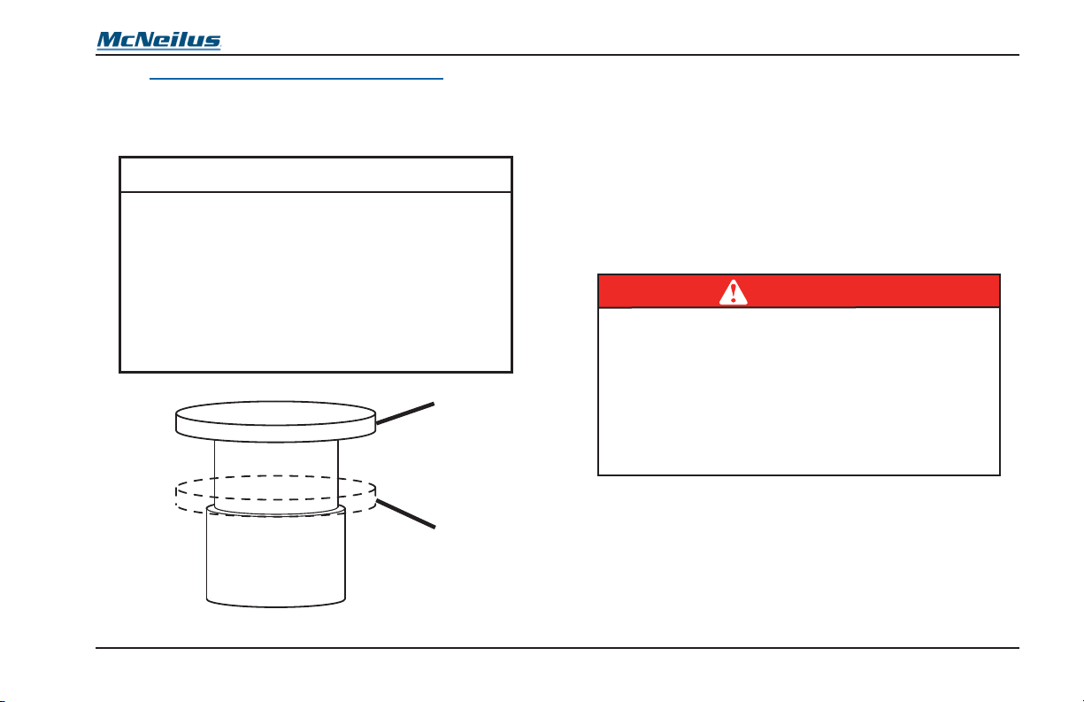
Operation
2
2.1.1 E-STOP Button In-Cab Control Box
The E-STOP on the control box has two position: DOWN
(Figure 15, Item 1) to disable refuse vehicle functions, and UP
(Figure 15, Item 2) for normal operation.
NOTE
If your rear loader has the optional side door
ladder, the door will be equipped with a
proximity switch. The proximity switch will
stop hydraulic functions during normal
operation if the side door is opened. To
resume hydraulic functions, the side door
must be closed and the pump switch must
be pressed to enable hydraulic functions.
1
Figure 15
2.2 Sweep Functions
The packing cycle of the sweep panel (Figure 16) is controlled
by the sweep lever located in the external rear controls group
on the curb side of the vehicle. The operator must follow ANSI
Z245.1 packing and material handling controls standard,
which includes directives that all personnel are clear of the
hopper before starting any packing cycle or material handling.
The operator must remain at the controls during the packing
cycle and be ready to stop the packing cycle if there is a
potential point of operation hazard.
DANGER
Use extreme caution around the sweep and
slide area on the rear of the vehicle. Be sure
the area in the hopper is clear before
operating the controls.
Serious personal injury or death may result if
someone is caught in the sweep or slide
panels.
CONDITIONS
• E-STOP(s) pulled OUT
• Pump switch ON
• Ensure that the side door is closed if equipped with side
door proximity switch
• Engine speed must be below 1400 RPM
© 2008 McNeilus Truck and Manufacturing, Inc.
47
Rear Loader

Operation
1
2
Figure 16
1. Sweep panel up and open.
2. Sweep panel down and closed.
Rear Loader
48
© 2008 McNeilus Truck and Manufacturing, Inc.

Operation
2.3 Slide Functions
Cycling of the Sweep and Slide Functions are controlled by
the sweep and slide levers, which are located at the rear of
the vehicle on the curb side. The operator must follow ANSI
Z245.1 packing and material handling controls standard,
which includes directives that all personnel are clear of the
hopper before starting any packing cycle or material handling.
The operator must remain at the controls during the packing
cycle and be ready to stop the packing cycle if there is a
potential point of operation hazard.
DANGER
Use extreme caution around the sweep and
slide area on the rear of the vehicle. Be sure
the area in the hopper is clear before
operating the controls.
Serious personal injury or death may result if
someone is caught in the sweep or slide
panels.
1. PUSH the slide lever to LOWER the panel down (Figure
17, Item 1). The function stops automatically when it hits
the fully lowered position, and the control lever returns to
its centered position.
2. PULL the slide lever to RAISE the slide panel up and
complete the packing cycle. This cycles the sweep and
slide panels up together (Figure 17, Item 2). The function
stops automatically when it hits the fully raised position,
and the control lever returns to its centered position.
1
2
Figure 17
1. Slide panel in the down position.
2. Sweep panel in the up position.
© 2008 McNeilus Truck and Manufacturing, Inc.
49
Rear Loader

Operation
2.4 Turnbuckle and Optional Hydraulic
Tailgate Lock Operation
NOTE
The warble alarm sounds when the tailgate
is opening and remains on until the tailgate
is closed.
The alarm does not sound if the ignition
switch is OFF or any of the E-STOP buttons
are pressed down.
2.4.1 Trucks Without Tag Axle (Turnbuckle)
One turnbuckle is present on each side of the lower rear
tailgate. These turnbuckles are safety devices that clamp
down and secure the tailgate to the collector body.
DANGER
Be sure all individuals are clear of the
tailgate area before opening the tailgate.
Remain attentive at all times.
Be sure you have adequate clearance above
the tailgate to prevent contact with buildings
or electrical lines.
Serious injury or death may result if
someone is caught in the path of the tailgate.
1. To unlock the turnbuckle, turn the handle
counterclockwise several times until it is loose.
2. Push the turnbuckle down to allow the tailgate to be
opened.
3. Repeat Steps 1 and 2 for the turnbuckle on the opposite
side of the vehicle.
4. Operate the tailgate controls to hydraulically open and
close the tailgate.
5. To lock the turnbuckle once the tailgate is closed, pull
the turnbuckle up and into the slot.
6. Turn the handle clockwise several times to clamp and
lock it in position.
7. Repeat Steps 5 and 6 on the opposite side of the
tailgate.
Rear Loader
50
© 2008 McNeilus Truck and Manufacturing, Inc.

Operation
2.4.2 Trucks With Tag Axle (Turnbuckle)
One turnbuckle is present on each side of the lower tailgate
(Figure 18). These turnbuckles are safety devices that clamp
down and secure the tailgate to the collector body.
DANGER
Be sure all individuals are clear of the
tailgate area before opening the tailgate.
Remain attentive at all times.
Be sure you have adequate clearance above
the tailgate to prevent contact with buildings
or electrical lines.
Serious injury or death may result if
someone is caught in the path of the tailgate.
1. Remove hair pin clip (Figure 18, Item 1) from the safety
pin (Figure 18, Item 2) and remove the safety pin.
2. To unlock turnbuckle, turn the handle (Figure 18, Item
3) counterclockwise several times until the turnbuckle is
loose.
3. Push turnbuckle down to allow the tailgate to be opened.
4. Repeat Steps 1, 2, and 3 for the turnbuckle on the
opposite side of the vehicle.
5. Operate the tailgate controls to open and close the
tailgate hydraulically.
6. To lock the turnbuckle once the tailgate is closed, pull
the turnbuckle up into the slot.
7. Turn the handle (Figure 18, Item 3) clockwise until tight
to clamp and lock tailgate into position.
8. Replace the hair pin clip (Figure 18, Item 1) into the
safety pin (Figure 18, Item 2).
9. Repeat Steps 6, 7, and 8 on the opposite side of the
tailgate.
3
1
2
Figure 18
© 2008 McNeilus Truck and Manufacturing, Inc.
51
Rear Loader

Operation
2.4.3 Hydraulic Tailgate Locks (Optional)
An optional hydraulic tailgate latch is available. The latches
are installed on both sides of the tailgate. The tailgate lock
function is controlled by a tailgate lock control lever usually
located at the outside front controls.
2.4.3.1 Unlock Tailgate (Hydraulic Locks)
1. To unlock tailgate, remove the pin (Figure 19, Item 1)
from latch (Figure 19, Item 2) and swing latch away from
tailgate lock (Figure 19, Item 3). Repeat this step for the
other side.
2. Lift up and hold control lever lock for tailgate lock control
lever.
3. Pull and hold the tailgate lock control lever to unlock the
tailgate lock.
2
3
Figure 19
1
Rear Loader
52
© 2008 McNeilus Truck and Manufacturing, Inc.

Operation
2.4.3.2 Lock Tailgate (Hydraulic Locks)
1. To lock tailgate, lift up and hold control lever lock for the
tailgate lock control lever.
2. Push and hold the tailgate lock control lever to lock the
tailgate lock (Figure 20, Item 1).
3. Move the latch (Figure 20, Item 2) back against the lock
and install the pin (Figure 20, Item 3) in the latch. Repeat
this step for the other side.
2
1
3
2.5 Tailgate Functions
Raising and lowering functions for the tailgate are controlled
by the tailgate lever on the street side of the vehicle.
DANGER
Be sure all individuals are clear of the
tailgate area before opening the tailgate.
Remain attentive at all times.
Be sure you have adequate clearance above
the tailgate to prevent contact with buildings
or electrical lines.
Serious injury or death may result if
someone is caught in the path of the tailgate.
NOTE
The turnbuckle locks must be manually
opened before the tailgate can be raised,
and must be manually latched and secured
before resuming travel or operation, or
before the truck is driven.
Figure 20
© 2008 McNeilus Truck and Manufacturing, Inc.
53
Rear Loader

Operation
1. To RAISE the tailgate, ensure that the turnbuckles or
optional hydraulic locks have been opened, then PULL
out the tailgate lever until the tailgate reaches the fully
open position (Figure 21).
NOTE
The warble alarm sounds when the tailgate
is opening and remains on until the tailgate
is closed.
The alarm does not sound if the ignition
switch is OFF or any of the E-STOP buttons
are pressed down.
2. To LOWER the tailgate, PUSH in the tailgate lever until
the tailgate reaches the fully closed position. After the
tailgate is lowered, be certain to latch and secure the
turnbuckles or the optional hydraulic locks before travel.
Figure 21
2.6 Ejector Functions
The ejector performs packing and retracting functions while
the collector is loaded, and ejecting the load when dumping.
The Smart-Pak® functions (Figure 22, Item 1) operate
automatically as the slide panel packs the container. A Smart-
Pak cartridge detects the amount of pressure being used.
When this reaches a pre-determined setting, the ejector
retracts to allow additional refuse to be packed. The functions
for the ejector are controlled by the ejector lever located on
the front external controls.
DANGER
Be sure all individuals are clear of the
tailgate area before opening the tailgate.
Remain attentive at all times.
Be sure you have adequate clearance above
the tailgate to prevent contact with buildings
or electrical lines.
Serious injury or death may result if
someone is caught in the path of the tailgate.
NOTE
The ejector contains an ejector force limiter
assembly which automatically controls the
maximum amount of force the ejector will
develop on Extend mode.
Rear Loader
54
© 2008 McNeilus Truck and Manufacturing, Inc.

Operation
1. To eject a load (Figure 22, Item 2), PUSH in the ejector
lever until the ejector reaches the full ejection of the
load.
2. To manually retract the ejector toward the front of the
container, PULL the ejector lever out.
1
2
Figure 22
1. Ejector direction during loading.
2. Ejector direction during unloading.
3.0 Operating Procedures
WARNING
Be sure all non-operator personnel are at
least 20 feet (6 meters) away from all areas
of the Packer.
Serious personal injury or death may occur.
DANGER
Make sure the area above the vehicle is
clear of objects and power lines before
raising or opening the tailgate.
Serious personal injury or death may occur.
NOTE
Turn the pump ON and idle the truck for a
minimum of five minutes before operating
the hydraulic functions when the air
temperature is 50° F (10° C) or below.
© 2008 McNeilus Truck and Manufacturing, Inc.
55
Rear Loader

Operation
WARNING
Do not leave the truck unattended until the
parking brake has been securely set and all
reasonable precautions have been taken to
prevent the movement of the truck. The
operator must chock the truck wheels
anytime he is away from the vehicle for an
extended period of time. Wheel chocks are
available for purchase from McNeilus Truck
and Manufacturing, Inc. by calling
888-686-7278.
Failure to comply may result in serious
personal injury or death or damage to
equipment.
3.1 Start-Up Procedure
Before starting the vehicle, make sure that:
1. Master battery switch is ON.
2. Daily Operator’s Checks have been completed and
veried.
3.2 Warm-Up Procedure
At start-up of the equipment each morning, it is important to
cycle through each of the main hydraulic circuits to be certain
each circuit is functioning properly. Cycling through each
operation also helps ensure that hydraulic uid, which is up to
operating temperature, is also present throughout the system.
CAUTION
If you detect a problem with any control
function, it must be repaired immediately.
Do NOT operate the Packer with malfunctioning controls.
1. Cycle through each of the following operations:
a. Sweep/Pack Functions - Cycle three (3) times
b. Slide Functions - Cycle three (3) times
c. Tailgate Lock Functions - Cycle one (1) time
d. Tailgate Functions - Cycle one (1) time
e. Ejector Functions - Cycle one (1) time
f. Optional Functions - Cycle one (1) time
2. After completing the cycle tests, inspect the refuse
vehicle for any hydraulic leaks. If leaks are detected,
correct them BEFORE the refuse vehicle is placed into
service.
WARNING
Never disable neutral safety or interlocks. Failure
to comply may result in serious injury or death
or damage to equipment.
Rear Loader
56
© 2008 McNeilus Truck and Manufacturing, Inc.

Operation
3.3 Traveling Procedure
Before beginning travel, be sure that all hydraulic functions are
turned OFF. This means that:
1. Pump switch is in the OFF position.
2. Throttle master switch is in the OFF position.
3. Tailgate is closed and turnbuckle is locked.
4. Winch or Reeving Cylinder cable (if equipped) is
retracted and latched to the correct location on the rear
of the vehicle.
DANGER
Turn the master switch in the cab to the OFF
position when the truck is being driven. Failure
to do so may result in serious personal injury
or death if the throttle engages while the truck
is being driven.
3.4 Before Starting The Route
If necessary, turn WORK lights ON to enhance vision.
Conditions
1. Turn PUMP rocker switch ON
2. Turn THROTTLE MASTER rocker switch ON
3. Extend ejector to rear of the body
4. Verify that the tailgate is locked
5. Turn STROBE light ON
6. Tailgate must be closed and locked.
3.5 Refuse Loading Procedure
Several distinct manners of loading refuse are included in this
operation, some of these involve optional equipment. (Specic
information on the functions for these options are covered in
Section 1.0 Instruments and Controls.)
3.5.1 Manual Trash Pick-Up
1. For general pick-up and processing of refuse.
a. Manually dump or place refuse into the hopper area.
b. Travel to the next pick-up site.
c. When the hopper area is sufciently lled, perform
the Refuse Packing Procedure as shown in Section 3.6
Refuse Packing Procedure.
© 2008 McNeilus Truck and Manufacturing, Inc.
57
Rear Loader

Operation
12
3.5.2 Residential Cart Loading (Optional Cart
Tipper)
1. For pick-up and processing of refuse when equipped
with the optional residential cart tipper.
a. Wheel the residential cart to the back of the cart
tipper.
b. Latch the cart onto the cart tipper (Figure 23, Item 1).
c. Pull the cart tipper dump lever to tip the cart and
dump refuse into the hopper (Figure 23, Item 2).
d. Unlatch and remove the cart.
e. Travel to the next pick-up site.
f. When the hopper area is sufciently lled, perform
the Refuse Packing Procedure as shown in Section
3.6 Refuse Packing Procedure.
Optional Street Side control is available.
3.5.3 Commercial Container Loading
WARNING
Be sure all non-operator personnel are clear
of the area around the truck before operating
the Packer. Remain attentive at all times
when operating the controls. Watch the
mirrors for activity. Never back up the
Packer unless and until you are completely
sure it is safe. Use a spotter/observer and/or
get out and check yourself, if necessary, to
ensure it is safe to do so. Thoroughly
understand the controls before operating the
Packer. Failure to heed this warning may
result in serious personal injury or death.
Rear Loader
Figure 23
58
© 2008 McNeilus Truck and Manufacturing, Inc.

WARNING
1
2
Crush or Pinch Hazard.
Lifting or dragging uncontrolled items with
hook and cable may cause items to move in a
way that can pinch or crush the operator.
Use winch or reeving cylinder hook and cable
for dumping properly restrained ANSI Type T
containers only.
Never use hook and cable for any other
purpose.
Failure to comply may injure or kill.
1. For all pick-up of refuse when equipped with a
Commercial Container option.
a. Position the vehicle in line with the commercial
container.
b. Connect the container to the container lock (see
Section 4.2 Container Lock).
c. Winch or Reeving Cylinder - If equipped, use the
Winch or Reeving Cylinder functions to tip the
container (Figure 24, Item 1). See Section 4.4 Winch
or Reeving Cylinder for more information.
d. Tipper - If equipped, use the Tipper functions to tip
the container (Figure 24, Item 2).
e. When tipping process is complete, return the
container to the ground, and detach it from the lock
mechanism.
Operation
f. Perform Refuse Packing Procedure as shown in
Section 3.6 Refuse Packing Procedure.
g. Travel to next pick-up site.
Figure 24
© 2008 McNeilus Truck and Manufacturing, Inc.
59
Rear Loader

Operation
3.6 Refuse Packing Procedure
Packing the refuse from the hopper employs a standard
process regardless of the manner in which the hopper was
lled. See Section 2.0 Control Functions. The sweep and
slide panels are normally in the up and packed position.
The operator must follow ANSI Z245.1 packing and material
handling controls standard, which includes directives that all
personnel are clear of the hopper before starting any packing
cycle or material handling. The operator must remain at the
controls during the packing cycle and be ready to stop the
packing cycle if there is a potential point of operation hazard.
To begin the packing procedure:
DANGER
Use extreme caution around the sweep and
slide area on the rear of the vehicle. Be sure
the area in the hopper is clear before
operating the controls.
Serious personal injury or death may result if
someone is caught in the sweep or slide
panels.
NOTE
Your vehicle is equipped with an ejector
force limiter which prevents the ejector from
overpacking the load and damaging the
Packer body.
1. Retract the sweep panel to the open position
(Figure 25, Item 1).
2. Extend the slide panel to the lower position
(Figure 25, Item 2).
3. Extend the sweep panel to the closed (pack) position
(Figure 25, Item 3). This “sweeps” the hopper area and
begins to pack the refuse.
4. Retract the slide panel to the raised position
(Figure 25, Item 4).
Rear Loader
60
© 2008 McNeilus Truck and Manufacturing, Inc.

Operation
1
2
3.7 Refuse Ejector Procedure
Ejecting refuse from the vehicle involves multiple functions.
DANGER
Do not back up until you are sure the area
behind the vehicle is clear.
1. Position rear loader appropriately for ejecting refuse.
3
Figure 25
1. Sweep panel in open position.
2. Slide panel in lower position.
3. Sweep panel in closed position.
4. Slide panel in raised position.
© 2008 McNeilus Truck and Manufacturing, Inc.
4
61
Be sure the area around the vehicle is clear of
non-operator personnel before and while
performing the refuse eject procedure.
Serious personal injury or death may result if
someone is near these areas while they are in
operation.
2. Unlock the turnbuckle (or optional hydraulic locks) and
open the tailgate. See Section 2.4 Turnbuckle and
Optional Hydraulic Tailgate Lock Operation and Section
2.5 Tailgate Functions for details.
3. Push the ejector control lever to dump the load (Figure
26).
4. Close the tailgate and lock the turnbuckle or optional
hydraulic lock.
5. Pull the ejector control lever to retract the ejector.
WARNING
Rear Loader

Operation
1. Tailgate Open Function.
2. Eject Function.
3.8 End of Day Checks
At the end of the day, make sure:
1. Tailgate is closed, turnbuckles are tight, or optional
hydraulic locks are closed.
2. All equipment is properly shut down (see the Vehicle
Operator’s Manual for more information on proper shut
down procedures for the engine).
Figure 26
Rear Loader
62
© 2008 McNeilus Truck and Manufacturing, Inc.

4.0 Optional Equipment
4.1 Residential Cart Tipper Panel
Controls for the cart tipper panel option are typically located
externally on the back of the truck, and consist of one or two
dump panels that can be attached in the center (for one) or
side-by-side (for two). The function is controlled by the cart
tipper lever, which is located at the rear of the vehicle on the
curb side.
WARNING
Be sure non-operator personnel are clear of the
hopper areas when operating the cart dump
panel. Serious personal injury or death may
result if someone is near the cart when the
function is operating.
1. PULL the cart tipper lever up to dump the residential cart
contents into the hopper (Figure 27).
2. PUSH the cart tipper lever down to lower the cart to the
ground.
Operation
Figure 27
© 2008 McNeilus Truck and Manufacturing, Inc.
63
Rear Loader

Operation
4.2 Container Lock
The container lock option is used in combination with either
the container tipper option, the winch, or reeving cylinder
option, and is used to secure and guide the collection of
refuse from commercial collection containers in a manner that
is both safe and efcient. To properly secure a commercial
container:
DANGER
Do not back up until you are sure the area
behind the vehicle is clear.
1. With the lock lugs open and the Container Latch guide
bars lowered (Figure 28, Item 1), back up the truck or roll
the container into position. Make certain the pins on the
container sides are correctly positioned tightly against the
guide bars on the vehicle.
2. Raise the container latch guide bars into position on each
side of the container (Figure 28, Item 2).
3. Lower and lock the lugs onto the container latch guide
bars on each side of the container (Figure 28, Item 3).
Make certain that both of the container latch guide bars
are securely latched.
4. Use the container tipper, winch, or reeving cylinder to
empty the container into the hopper (Figure 28, Item 4).
NOTE
The front of the container will slide down
along the guide rails as the rear of the
container is raised.
5. To release the container, reverse Steps 1 through 4.
1
3
2
4
Rear Loader
64
Figure 28
© 2008 McNeilus Truck and Manufacturing, Inc.

Operation
4.3 Container Tipper
This option is used in conjunction with the container latch to
safely and efciently dump the contents of large containers
into the hopper. To dump the contents of the container into the
hopper with the tipper:
WARNING
Be sure non-operator personnel are clear of
the hopper and area surrounding the cart
when operating the Tipper Functions. Serious
personal injury or death may result if
someone is near the cart when the tipper is
operating.
1. Guide the container pins (one on each side) into the
container latch. (See Section 4.2 Container Lock.)
NOTE
The tipper lever will return to center as soon
as it is released. It must be held for
continuous operation.
2. To empty the container, PULL and HOLD the tipper lever
out to slowly raise the container into the dump position.
Release the control lever when the container reaches the
dump position (Figure 29).
3. When the container has been emptied, PUSH and HOLD
in the tipper lever to slowly lower the container. Release
the container lever when the container is lowered to
ground level.
4. Release the container latch on each side of the container.
(See Section 4.2 Container Lock.)
Figure 29
© 2008 McNeilus Truck and Manufacturing, Inc.
65
Rear Loader
Operation
4.4 Winch or Reeving Cylinder
The winch or reeving cylinder options are used for dumping
the contents of large containers into the hopper. The winch or
reeving cylinder are controlled by a lever, located at the curb
side rear of the vehicle.
Your rear loader refuse truck may be equipped with a hook
and cable used for tipping commercial refuse containers into
the hopper. This hook and cable is specically designed to
work with ANSI Type T containers equipped with trunnion
bars and a lifting eyelet only when the container is properly
restrained with the trunnion bars in their receivers and the
latch bars engaged and locked. The hook should always be
attached directly to a lifting eye designed for this purpose,
never wrapped around an object and hooked back onto the
cable. The hook and cable are not intended for any other
purpose than dumping a Type T container into the hopper.
The hook and cable should not be used for lifting, dragging,
or manipulating containers, appliances, or other large items
toward or into the hopper.
WARNING
Be sure non-operator personnel are clear of
the hopper and area surrounding the cart
when operating the Winch Functions. Serious
personal injury or death may result if
someone is near the cart when the winch is
operating.
WARNING
Crush or Pinch Hazard.
Lifting or dragging uncontrolled items with
hook and cable may cause items to move in a
way that can pinch or crush the operator.
Use winch or reeving cylinder hook and cable
for dumping properly restrained ANSI Type T
containers only.
Never use hook and cable for any other
purpose.
Failure to comply may injure or kill.
1. Guide the container pins (one on each side) into the
container latch. (See Section 4.2 Container Lock.)
NOTE
The winch lever will return to center as soon
as it is released. It must be held for
continuous operation.
2. To empty the container, unhook the cable from its storage
latch, and then PULL and HOLD the winch/reeving lever
to extend the cable. Release the winch/reeving lever
when enough cable has been extended.
3. Attach the hook of the cable to the rear of the container
(Figure 30).
Rear Loader
66
© 2008 McNeilus Truck and Manufacturing, Inc.

Operation
1
Figure 30
4. PUSH and HOLD in the winch/reeving lever to retract the
cable and slowly raise the container to dump position.
Release the winch/reeving lever when the container
reaches the dump position.
5. When the container has been emptied, PULL the winch/
reeving lever to extend the cable and slowly lower
the container. Raise the winch/reeving lever when the
container is lowered to ground level.
6. Unhook the cable from the container, then carefully retract
and latch the hook to the cable ring provided (Figure 31).
Retract the cable further, just enough to “snug” it securely
to the ring.
© 2008 McNeilus Truck and Manufacturing, Inc.
Figure 31
7. Release the container latch on each side of the container
(See Section 4.2 Container Lock.).
67
Rear Loader

Operation
4.5 Lateral Protection Device
The lateral protection device (LPD) is designed to be
removed for service or rotated up or tilted forward for access
to components on the vehicle such as tool boxes, battery
boxes, hydraulic oil tanks. IMPORTANT: The only time the
LPD should be removed, rotated, or tilted is when the vehicle
is stationary. Return the LPD to its original position before
moving the vehicle or going on route.
Remove the LPD for Service
1. To remove the entire device to perform service work on
the vehicle, remove all four (4) hinge pins and move the
device out of the way.
2. Reinstall the device and all four (4) hinge pins to return
the LPD to its original position before moving the vehicle
or going on route.
Rotate the LPD Up
1. To rotate the lateral protection device up for access to
components, holding onto the rail assembly, remove the
lower hinge pin from both LPD mount supports.
2. Rotate the rail assembly up until the open holes on the
LPD mount support and the chassis mount align.
3. Install each lower hinge pin through the open holes in
the top hole of each LPD mount supports and mount
weldments (Figure 32).
Figure 32
4. Reverse all steps to return the LPD to its original position
before moving the vehicle or going on route.
Tilt the LPD Down
1. To tilt the lateral protection device down for top side
access to frame mounted components, holding onto the
rail assembly, remove the top hinge pin from both LPD rail
supports.
Rear Loader
68
© 2008 McNeilus Truck and Manufacturing, Inc.

2. Tilt the LPD down, keeping it hinged to the mount
weldments by the lower hinge pins (Figure 33).
Operation
Figure 33
3. Reverse the step to return the LPD to its original position
before moving the vehicle or going on route.
© 2008 McNeilus Truck and Manufacturing, Inc.
69
Rear Loader

NOTE
Operation
4.6 Auxiliary Axle
The following information is for auxiliary
axles installed by McNeilus Truck and
Manufacturing, Inc. Refer to chassis
manufacturer information for axle installed
by the chassis manufacturer or a third party.
The auxiliary axle down force is controlled by regulated air
pressure to the axle suspension air springs. The regulated
air pressure is preset at the factory to a common pressure
setting. Determine the actual regulated air pressure by
driving the vehicle over a truck scale at the various weights
the vehicle will be operated at up to the GVWR as shown on
the Final Stage Manufacturer Label located on the driver’s
side cab doorjamb (see Section 2 in the Foreword). Adjust
the regulated air pressure according to the auxiliary axle
manufacturer’s pressure/weight chart located in the cab
information packet supplied with the vehicle. The air pressure
gauge is located in the cab of the vehicle and may also be
located outside of the cab.
Always follow your company’s policies and procedures when
adjusting the air pressure. If you have any questions, call
McNeilus Parts and Service branches at 888-686-7278.
WARNING
Do not operate your vehicle until you have
determined the actual regulated air pressure
for the auxiliary axles. Improper regulated air
pressure will affect handling of the vehicle.
Failure to adjust and maintain the regulated
air pressure correctly may result in serious
personal injury or death.
A pusher axle option is mounted in front of the rear drive axle.
A tag axle option is mounted behind the rear drive axle. Either
axle is pneumatically applied, and is controlled by an option
switch on the cab console (see Section 1.0 Instruments and
Controls).
NOTE
Only lower the pusher axle after you have
started your route. Never lower the axle when
the packer is empty. When emptying the
packer, the pusher axle must be in the
raised position.
Rear Loader
70
© 2008 McNeilus Truck and Manufacturing, Inc.

4.6.1 Lowering the Pusher or Tag Axle
1. Bring the truck to a complete stop and apply the parking
brake (refer to the chassis manufacturer’s procedure).
2. Press DOWN on the PUSHER rocker switch or the TAG
rocker switch to lower the appropriate axle.
3. Resume normal operations.
NOTE
The pusher axle is designed to lift
automatically when the vehicle is put in
reverse. The axle must be lowered again
before beginning forward travel.
4.6.2 Raising the Pusher or Tag Axle
1. Bring the truck to a complete stop and apply the parking
brake (refer to the chassis manufacturer’s procedure).
2. Press UP on the PUSHER rocker switch or the TAG
rocker switch to raise the appropriate axle.
3. Resume normal operations.
Operation
© 2008 McNeilus Truck and Manufacturing, Inc.
71
Rear Loader

Operation
4.7 Water Tank
4.7.1 Water Tank Safety
WARNING
IMPORTANT ALUMINUM AND STEEL WATER
TANK INFORMATION.
1. Inspect water tank on a daily basis for
any damage including, but not limited to,
dents, gouges in metal, or leaks.
2. Do not weld on or repair water tank.
Instead, replace water tank with a new
OEM water tank.
3. Never pressure test an empty water tank.
Only pressure test a full water tank.
4. Never remove pressure regulator or pressure
safety valve from tank.
• If regulator or safety valve is defective, it must
be replaced before Packer is put into service.
5. Do not pressurize water tank beyond its
working pressure.
• If pressure exceeds the working pressure,
immediately depressurize water tank and
replace pressure regulator and pressure safety
valve.
Rear Loader
WARNING
CONTINUED
6. Never drive the truck with the water tank
pressurized.
• Depressurize water tank prior to transit to or
from job site.
• Water tank should be pressurized only when
being used.
7. Never modify water tank in any way.
8. Immediately replace safety decals with
McNeilus decals if decals are missing or
difficult to read.
9. Refer to the McNeilus Operator’s Manual or
contact McNeilus at 1-888-686-7278 if you have
questions or require assistance.
4.7.2 Introduction
Your vehicle may be equipped with a pressurized water tank.
This tank is used to rinse debris off the vehicle. Air pressure
from the vehicle’s brake system is used to provide pressure
to the tank. Use these instructions for the safe operation and
inspection of all McNeilus, Oshkosh, and London pressurized
water tanks.
If your vehicle is equipped with a non-pressurized water tank
(a system that uses a water pump to provide pressure), refer
to the instructions provided with the vehicle.
72
© 2008 McNeilus Truck and Manufacturing, Inc.

Operation
4.7.3 Daily Inspection
• Inspect tank daily for damage or leaks.
• Replace (do not repair) damaged or leaking tank.
• Drain pressure before driving.
• Do not weld or repair tank.
• Never exceed stated PSI in tank.
• Bursting tank may injure or kill.
4.7.3.1 Tank Integrity
At the start of each shift:
• Inspect Interior: Drain the tank of water and use a
ashlight to look into the tank through the ll opening.
Look for signs of corrosion on the inside of the tank which
may indicate that the tank has been weakened and is in
need of replacement.
• Inspect Exterior without Pressure: If the interior
inspection indicates that the tank is in good condition, ll
the tank with water and inspect the exterior of the tank
thoroughly for signs of leaks. Inspect the ller neck and ll
opening. Look for signs of damage. Look for cracks in the
weld joints or seams. Check that all fastening hardware is
tight and undamaged. Inspect ttings for signs of damage,
cracks, or looseness.
• Inspect Exterior with Pressure: If there are no signs
of damage or exterior leakage, pressurize the tank and
repeat the inspection.
• Depressurize Tank: Release the pressure in the tank as
soon as you are nished inspecting and before moving
the truck.
Replace Defective Tank: Water tanks with any leak or
signicant signs of internal or external damage or corrosion
should be replaced. DO NOT ATTEMPT TO REPAIR.
4.7.3.2 Pressure Regulator Valve
• Inspect Pressure Regulator: The pressure regulator
is used to reduce the air brake system pressure to a
pressure that is safe to be used in the water tank. It
must be undamaged and in proper working order. Look
and listen for signs of leaking. Ensure that the valve and
associated hoses and ttings are undamaged.
• Adjust Pressure to Correct Setting: Many pressure
regulators are set at the factory and cannot be adjusted.
If your water tank has an adjustable regulator, set it to 50
psi. When setting the regulator, always begin by turning
the adjusting knob counterclockwise rst to reduce the
pressure slightly. Then turn it clockwise slowly to bring the
pressure up to the correct setting. Never continue to turn
the valve past the correct setting.
• Replace Defective Regulator Valve: Any water tank with
a damaged or missing pressure regulator valve must be
removed from service immediately. Do not pressurize the
tank until a functioning pressure regulator valve has been
installed.
© 2008 McNeilus Truck and Manufacturing, Inc.
73
Rear Loader

Operation
4.7.3.3 Pressure Relief Valve
• Inspect the Relief Valve: The pressure relief valve is a
safety device that will release air or water from the tank if
it is inadvertently pressurized over the relief setting. The
relief setting on most water tanks is set at the factory and
cannot be adjusted. Identify the pressure relief valve and
ensure that it has not been damaged or tampered with.
• Replace Defective Relief Valve: Any water tank with
a damaged or missing pressure relief valve must be
removed from service immediately. Do not pressurize the
tank until a functioning pressure relief valve has been
installed.
4.7.4 Daily Operation
The water tank is designed to be used during stationary
operation at the yard or the landll site only. Do NOT
pressurize the tank while driving. A pressurized water tank is
an added hazard in the event of a crash or a rollover.
4.7.5 Vehicle Handling Characteristics
Safe operation of any vehicle is the responsibility of the driver.
The water tank is a uid load that can increase the rollover
tendency if the truck is driven with the water tank partially
full. To reduce the risk of rollover, only drive the truck with the
water tank either completely full or completely empty. Avoid
making sharp turns at excessive speeds and other abrupt
maneuvers.
In the event of a rollover or crash, an unbelted person is
signicantly more likely to become injured or die than a person
wearing a seat belt. ALWAYS WEAR YOUR SEAT BELT.
4.7.6 Water Tank Sign Identication
Item Part Number Qty. Comments
A 1449162 1 Use if equipped with 55 PSI tank.
A 1449165 1 Use if equipped with 95 PSI tank.
A 1503949 1 Use if equipped with 120 PSI tank.
B 1449164 1 Use on all tanks.
B
A
(Side Tank Mount)
Rear Loader
74
© 2008 McNeilus Truck and Manufacturing, Inc.
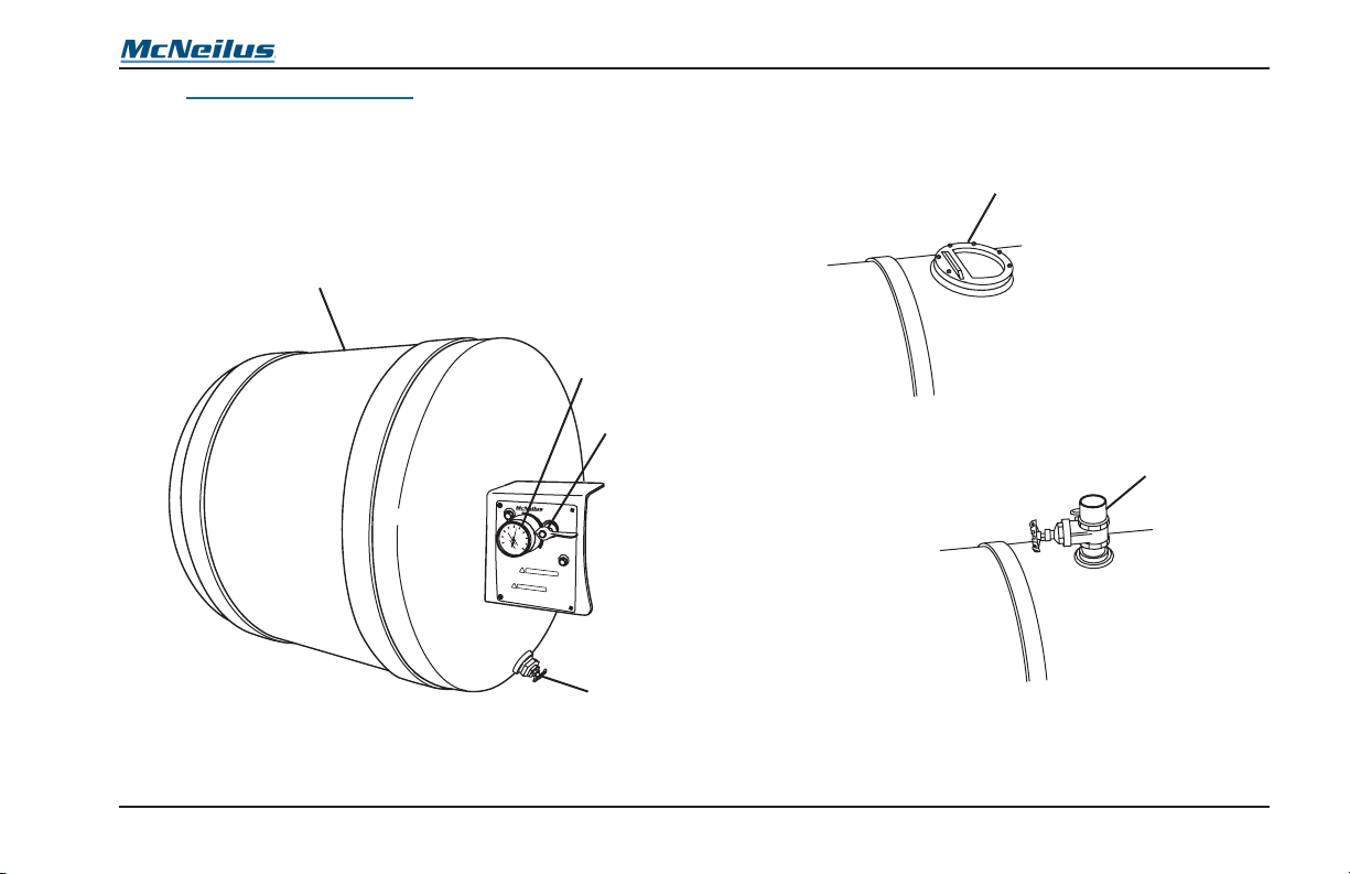
Operation
1
3
4
2
1
4.7.7 Water Tank Operation
The water tank (Figure 34, Item 1) can be mounted in any one
of several locations, depending on the options your refuse
vehicle is equipped with. The system will be equipped with a
pressure gauge (Figure 34, Item 2), an air pressure control
valve (Figure 34, Item 3), and a drain valve (Figure 34, Item
4).
2
P
RES
S
U
R
IZE
40
60
E
E
XHAUST
XH
AUST
20
8
0
0
10
0
O
F
F
PR
ESSUR
E
W
A
T
ER
SYS
TEM
!
W
ARN
IN
G
!
Figure 34
ADVERTENCIA
4.7.7.1 Filling the Tank
The tank can be lled through the opper valve (Figure 35,
Item 1) or through the optional gate valve (Figure 35, Item 2).
OR
Figure 35
© 2008 McNeilus Truck and Manufacturing, Inc.
75
Rear Loader

1
Operation
4.7.7.2 Pressurizing the Water Tank
WARNING
Never drive the truck with the water tank
pressurized.
Serious personal injury or death may occur.
WARNING
Never pressurize an empty water tank.
Serious personal injury or death may occur.
1. Fill the tank to the desired level.
WARNING
Pressure in the water tank should never
exceed 55 psi. If pressure exceeds 55 psi,
depressurize tank immediately and replace
with new McNeilus air regulator valve.
NEVER pressurize an empty tank.
NEVER modify tank in any way.
Operating in excess of 55 psi, pressurizing
an empty tank, or modifying the tank may
cause serious personal injury or death.
2. Turn the air pressure control valve to the PRESSURIZE
position (Figure 36, Item 1). The water tank will be
pressurized from the chassis air system.
3. The air gauge (Figure 36, Item 2) will read the pressure
in the water tank. The pressure must not exceed 55 psi.
PRESSUR
IZE
4
0
6
2
2
0
0
!
PR
ES
W
AT
ER
Figure 36
0
80
100
!
WAR
ADVERTENCIA
SURE
SYSTEM
EXHAUST
OFF
N
I
N
G
Rear Loader
76
© 2008 McNeilus Truck and Manufacturing, Inc.

Operation
2
1
4. Connect a hose to the tting (Figure 37, Item 1).
WARNING
Do not drink the water.
Serious internal injury may result.
5. Open the valve (Figure 37, Item 2).
2
Figure 37
1
4.7.7.3 Depressurizing the Water Tank
1. Turn air pressure control valve to the EXHAUST position
(Figure 38, Item 1). Make sure the gauges (Figure 38,
Item 2) read 0 psi.
PRESSUR
IZE
4
0
6
2
0
0
P
RES
W
AT
ER
0
10
!
ADVERTENCIA
!
SURE
SYSTEM
80
0
WAR
N
Figure 38
EXHAU
EXHAUST
ST
OFF
IN
G
© 2008 McNeilus Truck and Manufacturing, Inc.
77
Rear Loader

1
Operation
2. After pressure in the water tank has been completely
exhausted, turn the air pressure control valve to the OFF
position (Figure 39, Item 1).
PRESSURI
ZE
40
20
0
ADVERTENCIA
!
PRESSURE
WATER SYSTEM
60
80
100
!
WARNIN
EXHAUST
OFF
Figure 39
4.7.7.4 Draining the Water Tank
WARNING
Never allow the water from the tank to drain
onto a public sidewalk or roadway. Water
may cause the sidewalk or roadway to
become slippery. Always drain the water
system at a location designated by the job
site manager or in compliance with your
company policy.
Failure to comply may result in serious
personal injury or death.
WARNING
Do not drink the water.
Serious internal injury may result.
CAUTION
Be sure to drain the water tank, hoses, and
pipes when operating in temperatures below
freezing.
Failure to drain the system may cause
damage to equipment.
Rear Loader
78
© 2008 McNeilus Truck and Manufacturing, Inc.

Operation
1
When operating in temperatures below freezing, drain the
water system after every use.
1. Depressurize the water tank.
2. Open the tank drain valve (Figure 40, Item 1) and allow
the water to drain. When water is drained, close the
drain valve.
P
RESS
U
R
IZE
4
0
6
0
E
E
XHAU
XHAUST
S
20
8
0
0
100
!
!
ADVERTENCIA
T
OF
F
P
R
ES
SURE
W
AT
ER S
YSTEM
W
A
R
N
IN
G
3. Open gate valve(s) (Figure 41, Item 1) and drain all
hose(s) and pipe(s). Operate hose to drain hose and
pipes.
1
Figure 41
Figure 40
© 2008 McNeilus Truck and Manufacturing, Inc.
79
Rear Loader

Operation
NOTES
Rear Loader
80
© 2008 McNeilus Truck and Manufacturing, Inc.
Preventive Maintenance
1.0 Preventive Maintenance
Check or inspect the unit each day or before each new shift
of operation. Report any deciencies to your Maintenance
Department for correction by skilled service personnel.
CAUTION
Correct all identified deficiencies BEFORE
operating the Packer. Failure to correct
deficiencies may cause damage to
equipment.
1.1 DOT Pre-Trip
Preform pre-trip inspection of chassis and refuse vehicle
according to all federal, state, and local laws.
2.0 Preventive Maintenance
Intervals
Performing preventive maintenance on your refuse vehicle
will prolong the life of its equipment, help prevent expensive
downtime, and minimize the potential for problems arising on
the route.
The following Preventive Maintenance Chart summarizes the
requirements to properly maintain your refuse vehicle.
The chart species the recommended interval when each item
should be performed.
Intervals are listed in calendar and hours-of-use increments.
Maintenance should be performed at the increment that
occurs rst.
The preventive maintenance intervals listed under the Service
group heading are the maximum days or hours allowed
for each maintenance procedure. Continue to repeat the
maintenance procedures at the listed intervals.
NOTE
If the Packer is operated more hours per
day or double-shifted, the maintenance
interval must be adjusted accordingly.
© 2008 McNeilus Truck and Manufacturing, Inc.
81
Rear Loader

Preventive Maintenance
The Preventive Maintenance Chart identies the
responsibilities to be performed by both the operator and
service personnel.
Some maintenance procedures are listed under both the
Operator group heading and Service group heading.
The Daily Checks under the Operator group heading identify
procedures that can be performed by either the operator or
skilled service personnel.
All intervals listed under the Service group heading must be
performed by skilled personnel. Refer to the product Service
Manual for descriptions of maintenance procedures.
Maintenance procedures are listed under the appropriate
affected refuse vehicle system.
Rear Loader
82
© 2008 McNeilus Truck and Manufacturing, Inc.

Preventive Maintenance
Daily Checks
(10 Hours)
(50 Hours)
Scheduled PM
(150 Hours)
Semi-Annual
(1250 Hours)
Annuall
(2500 Hours
Bi-Annua
(5000 Hours)
LEGEND
R Replace P Perform
I Inspect L Lubricate
T Torque C Clean
Hydraulic System
Hydraulic Oil Level
Hydraulic System and Components
Hydraulic Hoses
Hydraulic Tubes and Pipes
Breather Filter
Return Line Filter
Hydraulic Oil Test
HOC Operation Test
Main Relief Valve Setting
Hydraulic Oil
Reservoir Drain Plug
Suction Line Strainer
Complete all prior maintenance items before proceeding to any hourly service interval.
P P
I I
I I
I I
Operator
Daily
Weekly
I/R R
I/P I/P
R
P
P
P
R R
R R
Service
y
)
l
© 2008 McNeilus Truck and Manufacturing, Inc.
83
Rear Loader

Daily Checks
(10 Hours)
(50 Hours)
Scheduled PM
(150 Hours)
Semi-Annual
(1250 Hours)
Annuall
(2500 Hours
Bi-Annua
(5000 Hours)
Preventive Maintenance
LEGEND
R Replace P Perform
I Inspect L Lubricate
T Torque C Clean
Electrical System
Lighting System
Wire Harness
Audible Back-up Alarm
Mechanical
Refuse Vehicle Body and Components
Tailgate Seal Condition
Sweep and Slide Panels
Ejector Track Clearance
Automatic Neutral Interlock
Winch Gearbox Oil
Cylinder pins, bolts, and fasteners
Winch or Reeving Cylinder Cable
Inspect for excessive wear, corrosion, kinks
Complete all prior maintenance items before proceeding to any hourly service interval.
I I
I I
I
I I
I C
I I
Operator
Daily
Weekly
I
I
I P/C
I
I
Service
y
)
l
Rear Loader
84
© 2008 McNeilus Truck and Manufacturing, Inc.

Preventive Maintenance
Daily Checks
(10 Hours)
(50 Hours)
Scheduled PM
(150 Hours)
Semi-Annual
(1250 Hours)
Annuall
(2500 Hours
Bi-Annua
(5000 Hours)
LEGEND
R Replace P Perform
I Inspect L Lubricate
T Torque C Clean
Operation
Refuse Vehicle Controls
Trash Behind Ejector
Safety Signs
Lubrication
Daily
Scheduled PM
Complete all prior maintenance items before proceeding to any hourly service interval.
P P
I/P I/P
I
L
Operator
Daily
Weekly
Service
)
y
l
L
© 2008 McNeilus Truck and Manufacturing, Inc.
85
Rear Loader

Preventive Maintenance
3.0 Daily Preventive Maintenance
Checks
3.1 Hydraulic System
Make sure all necessary service and maintenance is complete
before the truck leaves the facilities and before operation.
SAFETY NOTICE
Perform your company’s Lockout/Tagout
procedure. If your company does not have a
Lockout/Tagout procedure, follow OSHA
1910.147 and 1910.146 Confined Space as
appropriate.
3.1.1 Hydraulic Oil Level
• Daily Checks - The oil level is checked by the operator or
skilled service personnel.
NOTE
Check hydraulic oil level during start-up
when the oil temperature is still cold.
• Check the hydraulic oil level with all hydraulic cylinders in
their fully RETRACTED position.
3.1.1.1 Temperature/Level Sight Gauges
Use the temperature/level gauge (Figure 42, Item 1 and Item
2) to determine how much oil is in the reservoir.
1
ºc
80
70
60
50
40
30
20
10
0
-10
2
Figure 42
Rear Loader
86
© 2008 McNeilus Truck and Manufacturing, Inc.
 Loading...