

Page 1
8 ZONES AUDIO/ VIDEO MULTI-ROOM/
SOURCES DISTRIBUTION AMPLIFIER
AVD-800P
If you are looking for a security (Indoor & Outdoor) with the
multi zones provided for both Audio/Video Sources, and to
improve your unique lifestyle, we are proud to introduce
you the high quality McLELLAND AVD-800P.
Page 2
Page 3
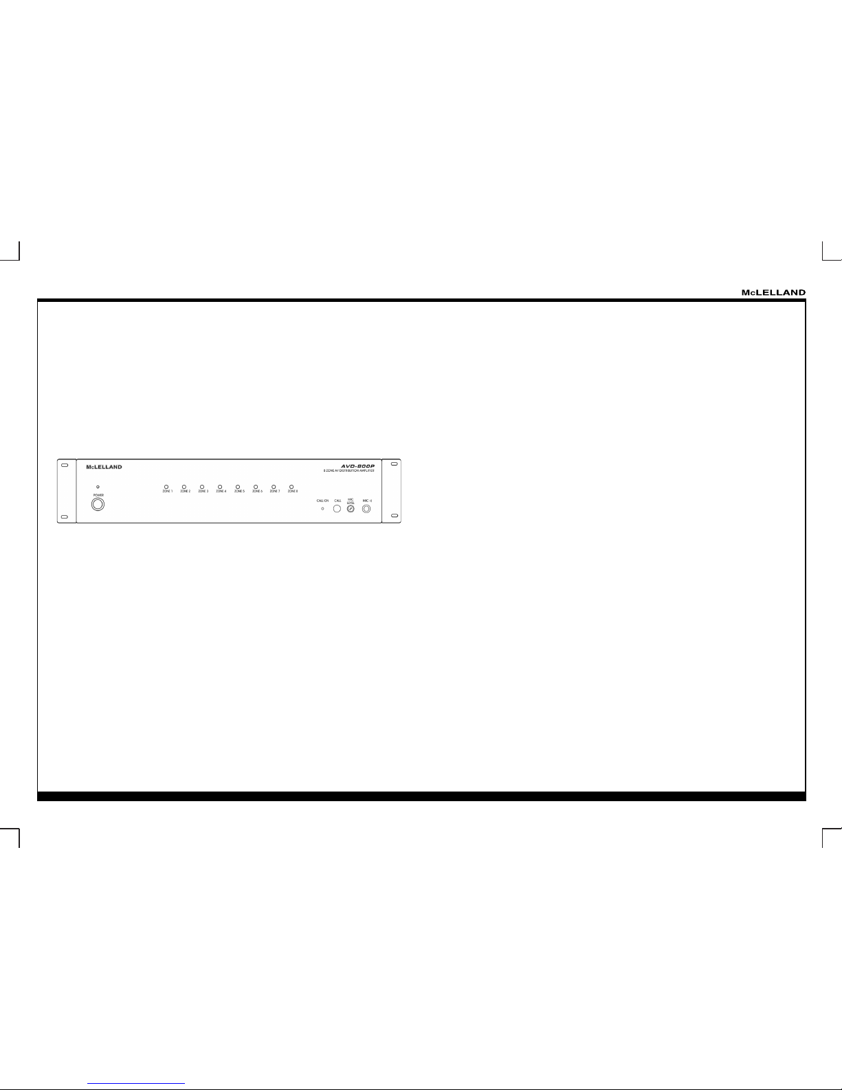
8 ZONES AUDIO/ VIDEO MULTI-ROOM/
SOURCES DISTRIBUTION AMPLIFIER
AVD-800P
ABOUT THE INSTALLATION
Thank you for inviting the McLelland AVD-800P Audio/Video Distribution System into your home/security
place. The following is a quick setup guide for general system installation and operation of the AVD-800P.
Step 1: Place the AVD-800P amplifer in its preferred location. The AVD-800P amplifer is designed to be
located in the central control area where the home's audio sources will be housed.
Step 2: The AVD-800P amplifier should be turned on before any other cables are attached to it. This
activates internal protective circuitry. Once the AVD-800P amplifer is turned on, it should be left on.
Step 3: Connect the audio/video sources to the AVD-800P inputs using standard stereo RCA cables.
Step 4: Connect the video camera sources to the AVD-800P inputs using an RJ-45 CAT5 cables.
Step 5: Using the CAT5 cable in the RJ-45 connection jack on the back of the Keypad and in the
Keypad Comm connector on the back of the AVD-800P amplifer.
Step 6: When the Keypads are added to each zone, the system will poll for available zones and allow
you to choose the appropriate zone number for that keypad. Once a zone number is assigned the
keypad will assume control of the zone.
SYSTEM OVERVIEW
The AVD-800P is a Ten-source Eight-zone audio/video distribution control system amplifier.
The system is included the Control Amplifer, Eight Keypads, Remote Controller and also the IR
Emitter can be purchase as an accessories. Together the control amp and the keypads make up a
Whole-House Audio/Video Security Entertainment System.
The AVD-800P is shipped to operate basic functions without any programming. Simply by
plugging in keypads via standard CAT-5 RJ45 terminated patch cable and powering the controller
‘on’, you can control the Source Selection, Volume Up/Down and Speaker Mute capabilities.
The System Feature:
* Output Power: 20W x 8 Zone (16 Channels).
* UTP CAT5 Transmission System
* 8 RJ45 Connectors: For keypads including video signal output.
* Control the Volume / Treble / Bass / Source / Mute / Balance of each Eight zones from the HRC-1
Remote Controller.
* Two Control Amps can be linked to create systems with up to Sixteen Zones
(Maximum Expand System: 16 x AVD-800P for 128 Zones)
* Independent IR Emitter output for each zone.
* Trigger On and External Mute jack on rear panel.
* DIP switch for AGC level and AGC off on rear panel.
* Distribute amplifed Stereo Audio and Video from Ten Independent source to Eight Separate Zones
* Power Supply: AC 115V 60 Hz / 230V 50 Hz, Can be switched.
* Dimension: D 413 x H 88 x W 427 mm.
The AVD-800P System includes the following components:
* AVD-800P Controller / Amplifer x 1
* AVD-KP1 Keypads x 8
* KP-C Cover x 24 (Black x 8 + Almond x 8 + White x 8)
* WPC Cover x 24 (Black x 8 + Almond x 8 + White x 8)
* HRC-1 Remote Control x 1
* AVD-800P System Installation Instructions
Optional Accessories:
* IE-1 IR Emitter
* AVD-KP1 Kit or AVD-KP2 Kit x 1
Remark:
AVD-KP1 Kit include:
AVD-KP2 Kit include:
* AVD-KP2 Keypads x 8
* HRC-1 Remote Control x 1
Page 4
8 ZONES AUDIO/ VIDEO MULTI-ROOM/
SOURCES DISTRIBUTION AMPLIFIER
AVD-800P
The design is powerful to combine and distribute audio/ video security
Camera sources with this unique unit in your site-place.
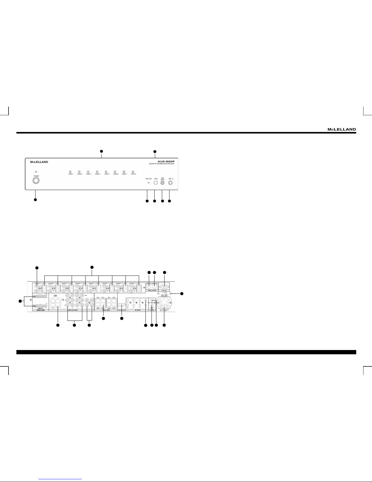
AVD-800P REAR PANEL FEATURES AND CONNECTIONS
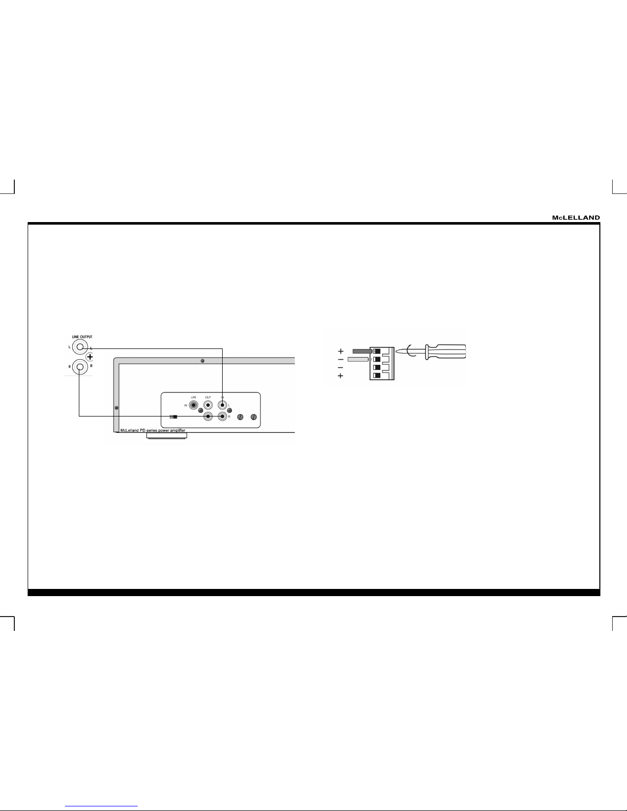
1. Preamp Line Out (1-8): L+R stereo RCA Jacks for connecting Zone Audio Output to an external
amplifer. For use with applications where either more power is required for Zone (see Figure 1)
2. Zone Speaker Output (1-8): Use the included 4-conductor plug-in connector, (8 included) to connect
speaker wires to the AVD-800P (see Figure 2)
3. Inter Data Loop: This RS-485 data controller can loop control up to 16 AVD-800P units of expand to
128 places (see Figure 3)
4. Control Pad: which connected with the system controller; it can control the Eight zone’s
keypads.
5. Call LED: The Call LED Jack (D-SUB 9 Pin) on the rear panel can connect with Call LED Display Box,
when user prints anyone of the zone “Call” key press, the corresponding zone LED will be illuminant and
active sounder.
6. Voltage Select: Can be switched between AC 115V 60 Hz / 230V 50 Hz.
7. AC Power Input: Standard IEC 3-Conductor AC Line Cord Receptacle for plug-in of a 3-conductot
power line cord.
8. SYS Trigger: The System Trigger Jack will be showing the H (DC 12V) output when the all 8 zone
sources were powered on or at least one zone is powered on.
The System Trigger Jack will be showing the L (DC 0V) output when the all 8 zone sources were
powered off.
9. External Mute: When the extra DC 3-12V input used by this Jack, it will be show the Mute condition
with all zones of AVD-800P.
10. IR Remote Emitter (1-8): Those 3.5mm Mono Mini Phone Jacks are use for plug the supplied IR
emitters into the appropriate IR Emitter jacks to individually control the 8 common source components.
(see Figure 4)
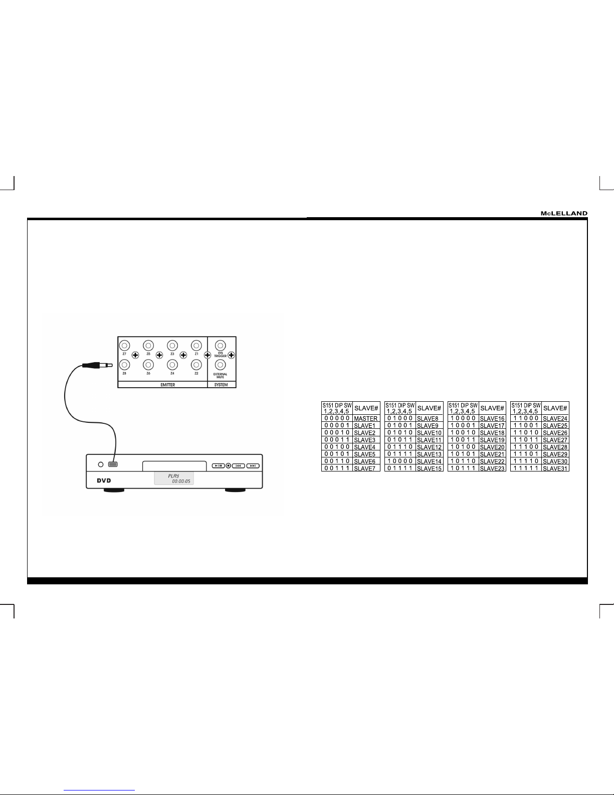
11. AGC/Address Select: Using the Address & AGC (Auto Gain Control), no need to regulate the
volume of each source, the volume of output will automatic to be ranged at the same level. (see Figure 5)
12. Keypad Output (1-8): Each Zone has one RJ-45 jack for keypad interface. Connect the zone CAT5
cable to the Keypad Output Terminal n the AVD-800P keypad rear panel. (see Figure 6 & 7)
13. Zone Audio Input: Stereo RCA Jacks for stereo line level audio input from source. (see Figure 8)
14. Zone Audio/Video Input: RCA Jacks for composite video input from source components. (see
Figure 9)
15. Video Camera Input: Which designed used the UTP camera as mainstream do the bidirectional
electric transfers by CAT5 cables/connectors, it will be had no use for another power and transfer could
be controller remotely.
16. Input Source (Signal) Loop In/Out: Re-In/Output 10 Audio/Video sources to other AVD-800P with
IDC Flat Cable.
1
2
543
6
10
9 8 7
1112
131415
16
1. Front Panel.
2. Master Power On/Off Switch: Turns AC power On/Off to the entire unit.
3. Zone LED Indicators: Eight indicators, one for each Zone
4. Microphone Input: Use this jack to connect a mircophone to the amplifer.
5. Mic Level Control: Use this VR to adjust the microphone volume without changing the overall mix
6. Call: The Call function can be turned on with this button.
7. Call On: This LED lights to indicate when the Call function has be turn on.
2
7 6 5 4
1
3
AVD-800P FRONT PANEL FEATURES AND CONNECTIONS
Page 5
8 ZONES AUDIO/ VIDEO MULTI-ROOM/
SOURCES DISTRIBUTION AMPLIFIER
AVD-800P
Figure 1: Preamp Line Out
Each Zone has a Preamp Out to send “Zone Selected” by L+R stereo RCA Jacks for use with applications where either more power is required for Zone or passing to other separate higher power amplifer,
such as the McLelland PD-100/200/500 or PD-300/600SB.
Figure 2: Speaker Connections
Each conductor is screwed down to connector block and plugged into the speaker output on the back of
the amplifer. The AVD-800P speaker terminals (amplifer output) are 8 ohms safe, please be sure to cor rect polarity by connecting the “+” and “-“ terminal from each channel on the AVD-800P to the corresponding “+” and “-“ terminal on each speaker. Also need to check the combined impedance presented to the
speaker terminals by the speaker is 8 ohms minimum.
Figure 3: Zone Expansion (Connecting Two AVD-800P Controller)
When linking two units together, designate one unit as the Primary Unit (Zone 1~8) and the other unit as
the Secondary Unit (Zone 9~16). All source components should be connected directly to the Primary Unit
Source A/V Input. Us the Primary Units Audio and Video Loop to feed the source component inputs of
the Secondary Unit.
* All of the source components emitters should be connected directly to the Primary Unit IR Emitter Output Ports.
Page 6
8 ZONES AUDIO/ VIDEO MULTI-ROOM/
SOURCES DISTRIBUTION AMPLIFIER
AVD-800P
Figure 5: ADDRESS/AGC DIP Switch Setting
The AVD-800P DIP switch show the 7 Pin through Check selection, the 1-5 are Address Select, Pin 6
is the front panel broadcast function selection and when the Pin 6 is at "1" position , this unit show the
broadcast to the zone which has powered on, when Pin 6 is at "0" position, if used broadcast, the unit will
cut all the zone and show the broadcast through these although the zone at the Standby position, it will
be also cut to broadcase.
Pin7 = AGC Select,
0 = AGC Enable,
1 = AGC Disable.
For Example: If Master = DIP SW 12345 switch to the "0" position, Slave 1 = DIP SW 1234 switch to the
"0" position, SW 5 switch to the "1" position.
Note: All the modifcation of the DIP Switch ( including AGC ) must be action after the restart of the AVD800P
Figure 4: IR Emitters Connections
There is Eight IR emitters are supplied with your AVD-800P System, which can be IR Commands for the
source equipment are transferred from the AVD-800P amplifer to the source equipment using the mini
IR emitters. Just plugged into the corresponding source IR output on the AVD-800P and then placed
over the IR receiver window on the source component. Compatible with most brands of remote controls,
though some may not be programmable and will therefore only control the source components.
EX: If Master = DIP SW 12345 switch to the "0" position, Slave 1 = DIP SW 1234 switch to the "0" position, SW 5 switch to the "1" position.
Note: All the modifcation of the DIP Switch ( including AGC ) must be action after the restart of the AVD800P
Page 7
8 ZONES AUDIO/ VIDEO MULTI-ROOM/
SOURCES DISTRIBUTION AMPLIFIER
AVD-800P
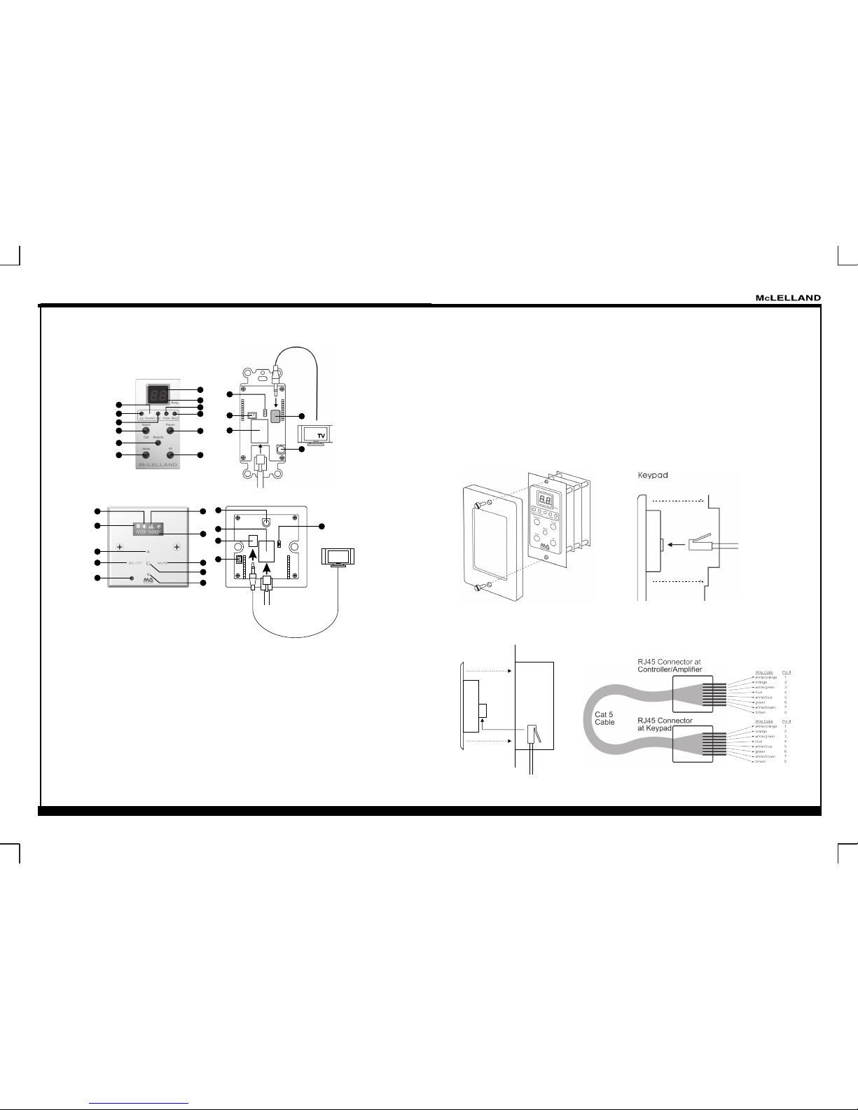
1.Power: Turns the zone ON an OFF. Can be programmed with IR codes or sequences.
2.Select (Call): This bottom can be use for selected the system function of each zone, and also can be use as for
panic call button (hold 3 sec)
3.Remote (IR Sensor): The keypad gas build-in receiver for complete wireless control , also can be receives IR
from hand-held remotes to control both source components and the AVD-800P system.
4.Display: When the zone power is ON, the display will indicate the selected source, zone volume, treble or bass.
5.Up: Increases zone source/volume/treble/bass, depends which function is selected.
6.Down: Decreases zone source/volume/treble/bass, depends which function is selected.
7.Vol: This LED lights to indicate when the volume function has be select
8.Function: The function led show the connection well with the main unit AVD-800p by the cables
9.Call: This LED lights to indicate when the Call function has be turn on.
10.Treble: This LED lights to indicate when the treble function has be select
11.Bass: This LED lights to indicate when the bass function has be select.
12.Busy:When the Busy LED came to light, it show that the control circuitry was busy, if on this station,
the operation of keypad or remote control will be incorrectness.
Figure 6: Keypad Panel Features And Functions
Figure 7: Keypad Installation
Keypad mounting for the AVD-KP1 has no need a junction box, which can be mounted on
drywall, button board or other surfaces covering a hollow wall.
CAT-5
Rj45
wall
14.Controller Terminal: RJ45 Jack connects Keypad to zone keypad input on AVD-800P controller via
CAT5 cable.
15.Video Output: RCA Jack connects Keypad to TV or Monitor.
16.Camera Scan Switch:
When Open, the camera (Source 7-10) Disable, Camera can not be output from
Keypad and IR Remote Control Camera Scan Key Disable Operation)
When Short, the camera resume to action ( Camera Enable / Disable must be re-power on)
17. Call Tact Switch Connection Jack:
Action as Call Key of IR Remote.
18. Video Gain Control SVR:
Adjust Video output of Keypad, adjustable range 0-+6dB
AVD- KP1 C ont rol Key pad
AVD- KP2 Tou ch Se nso r
Con trol Ke ypad
18
15
14
12
11
9
8
7
6
4
3
1
2
5
10
16
17
TV
5
2
1
3
4
6
7
8
10
14
15
16
17
18
13
13.Mute: It allows you to mute the corresponding zone.
Keypad mounting for the AVD-KP2 just put in a junction box and fix it with screws.
wal l
jun ction
box
RJ4 5
CAT-5
key pad
Page 8
8 ZONES AUDIO/ VIDEO MULTI-ROOM/
SOURCES DISTRIBUTION AMPLIFIER
AVD-800P
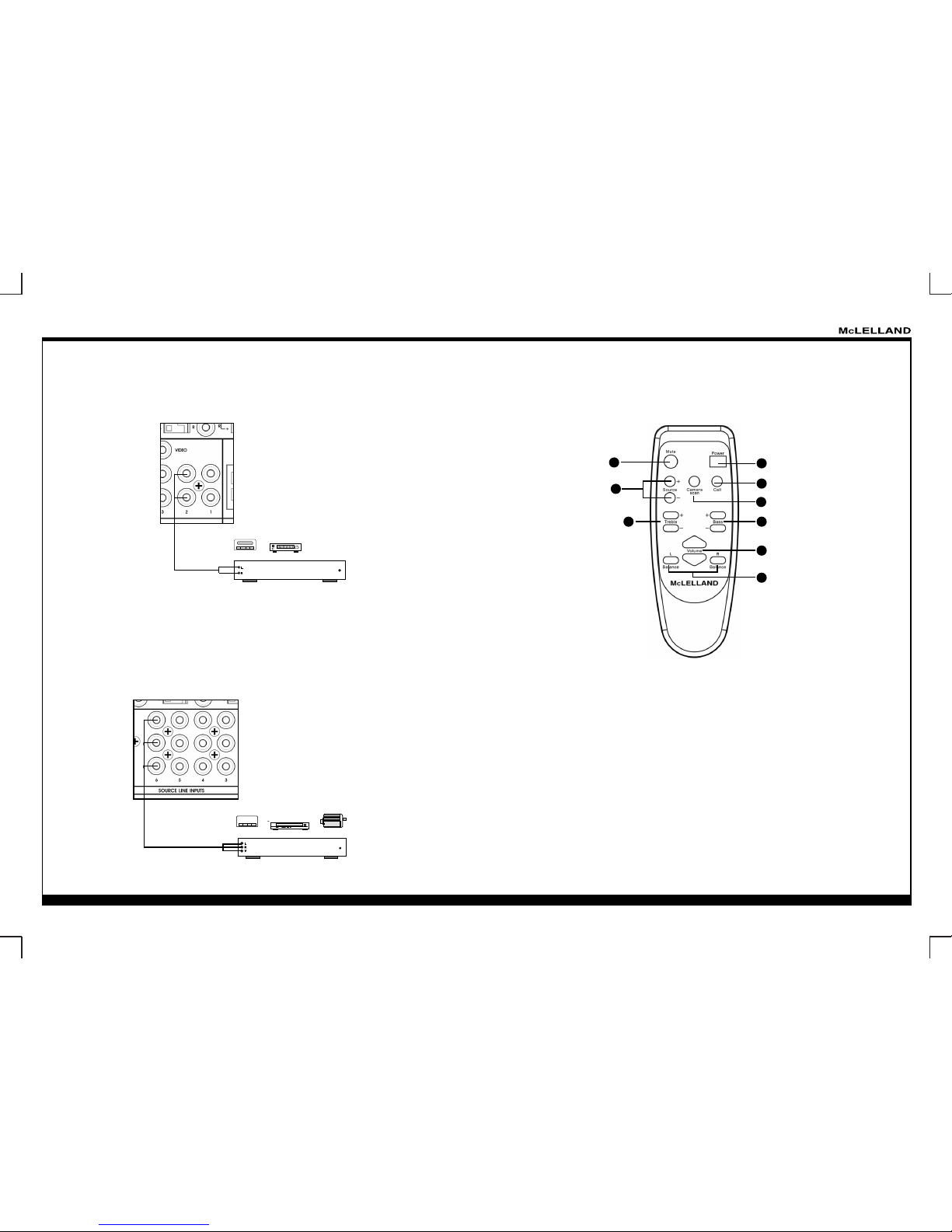
Figure 8: Audio Connections
Using the RCA type patch cables connect the Left and Right Output jacks of the source component (CD,
Tuner, etc) to the appropriate source Audio Left and Audio Right Input Jacks on the AVD-800P.
Figure 9: Video Connections:
Using the RCA type patch cables connect the Video and Audio (Left/Right) Output jacks of the source
component (DVD Player, DVB, DV) to the appropriate source Video and Audio (Left/ Right) Input Jacks
on the AVD-800P.
CD Tuner
DVB
DVD
DV
Remote Control
1. Power:
This button is for power switches (On/Off) for the certain zone.
2. Call :
This button is turn on the call function.
3. Mute:
It allows you to mute a certain zone.
4. BAL:
These L & R buttons can adjust the balance of L/R channel in stereo mode.
5. VOL:
Volume adjustment for users.
6. Source:
Used to select signal input.
7. Treble:
This allows you to enhance or reduce Treble of signal in individual zone.
8. Bass:
This allows you to adjust the Bass for the individual zone
9. Camera Scan Switch:
This button is turn on/off the Camera Scan function. When the function is
turn on, all video camera input sources will display-sequence switching from source 7 to 10.
3
6
7
1
2
8
5
4
9
Page 9
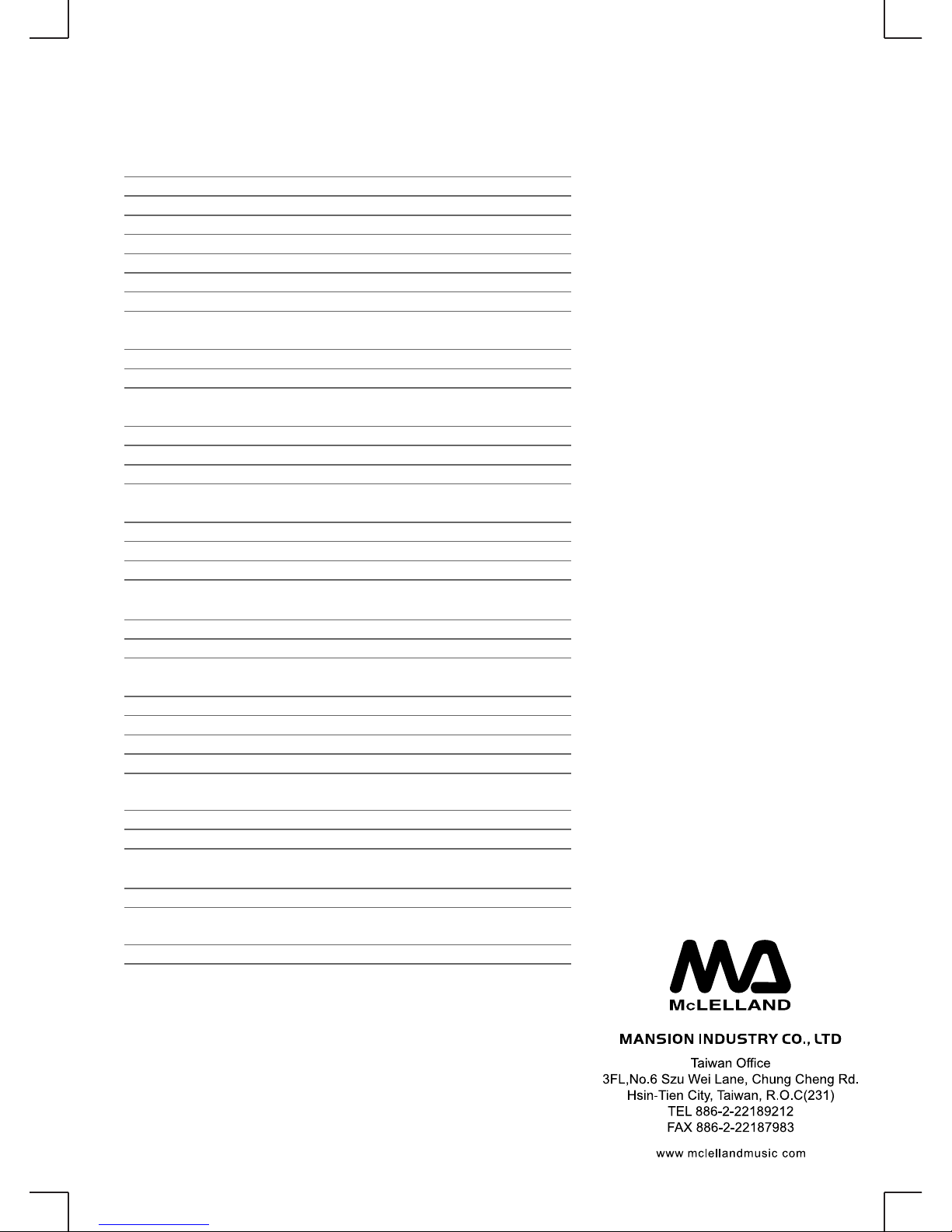
AVD-800P SPECIFICATION
Zones 1-8 Power Amplifier Outputs
Continuous Average Output Power
Two channels driven 30-20kHz @10%TH D
Rated Distortion (1/2 power)
Rated Impedance
Frequency Response
Bass Control Range
Treble Control Range
Zones 1-8 Preamplifier Outputs
Varivale output
Impedance
Audio Source Inputs 1-2
Input Impedance
Input Sensitivity for rated power
Input Overload
Audio/Video Source Inputs 3-6
Input Impedance
Input Sensitivity for rated power
Input Overload
Video Source Inputs 3-10
Input Impedance
Input Sensitivity for rated power
Emitter Outputs
Source Outputs
Output Drive Current
Output Drive Voltage
Compatible with single and dual emitters
System
System On (output)
External Mute (input)
Power Requirements
Power Supply
Power Consumption all channels driven to
full-rated power driven to full-rated power
Power Consumption no signal
20W/channel(2 channels/zone)
0.4 %
8 Ohms
20-20kHz +/- 2dB
+/- 9 dB @ 100 Hz
+/- 9 dB @ 10 KHz
1 V
600 Ohms
20K
300 mV RMS
2V RMS
20K
600 mV RMS
3V RMS
75 Ohm
1.0V P to P
8
100mA
5V
12V @ 50m A
3-12V DC
117VAC/230VAC 50/60H z
750VA
50VA (25W)
 Loading...