

Page 1
VISION FLX2
MANUAL
AUG 22, 2016
833-083
Page 2
1
Fault finding manual
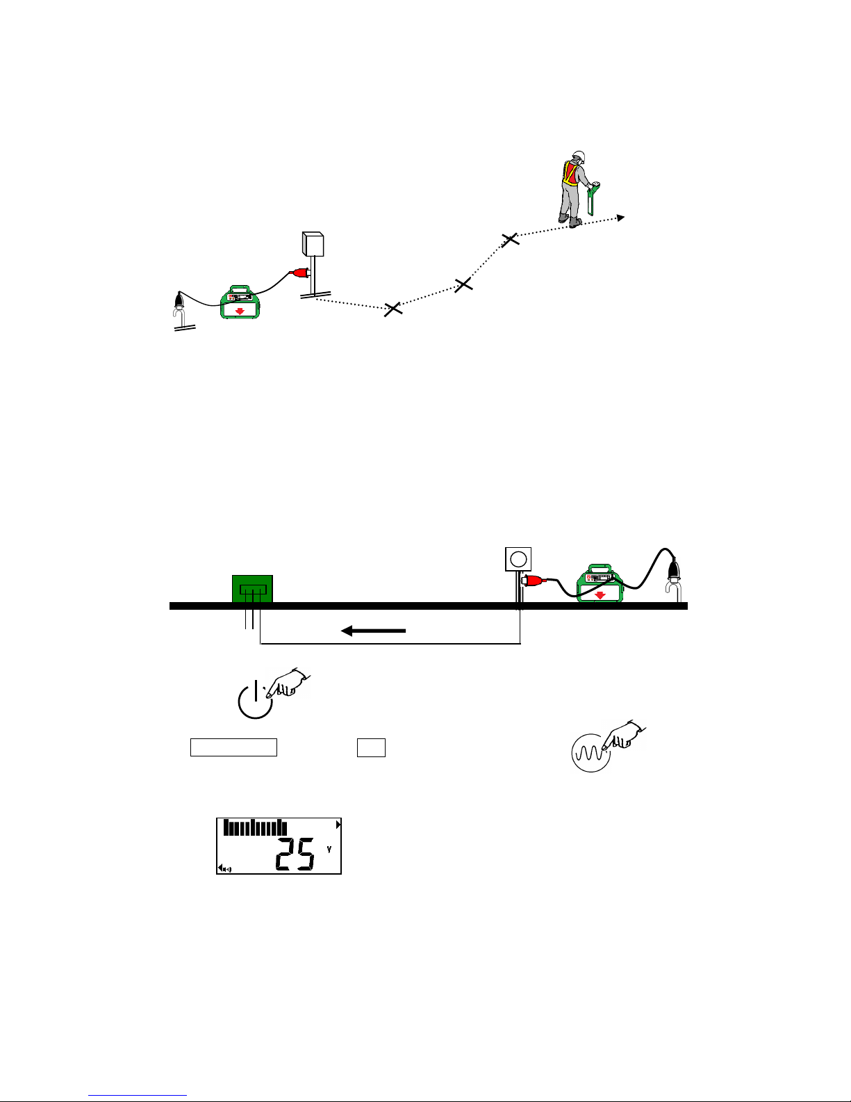
Step 1 – Locate and mark the utility
TRANSMITTER
Step 2
CHECKING CABLE FOR VOLTAGE
Ground stake should be placed directly behind and in the opposite direction of the
cable path.
Connect the black end of the direct connection cables to the ground stake.
Connect the red end of the direct connection cables on the cable to be checked.
Power on.
Press Frequency , and select FF . *FF is Fault Find mode.
Voltage is indicated. When voltage is greater than 25 volts, alarm sounds.
Cable Path
Ground
Stake
Meter
Transformer
Transmitter
Page 3
2
Step 3
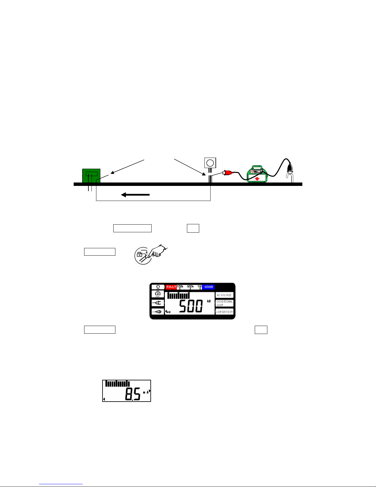
CHECKING CABLE RESISTANCE
This feature is used to determine the quality of the fault.
Isolate both ends of the cable.
Ground stake should be placed directly behind and in the opposite direction of the
cable path.
Connect the black end of the direct connection cables to the ground stake.
Connect the red end of the direct connection cables on the cable to be checked.
Power on. Press Frequency , and select FF .
Press ADJUST .
Resistance is indicated by the numerical value and the bar graph.
Press ADJUST again or 30 sec. later, the display is returned to the FF .
Step 4
FAULT FINDING
After measurement of the resistance, fault finding power is adjusted automatically.
Isolate both ends
Cable Pa
th
Page 4
3
RECEIVER
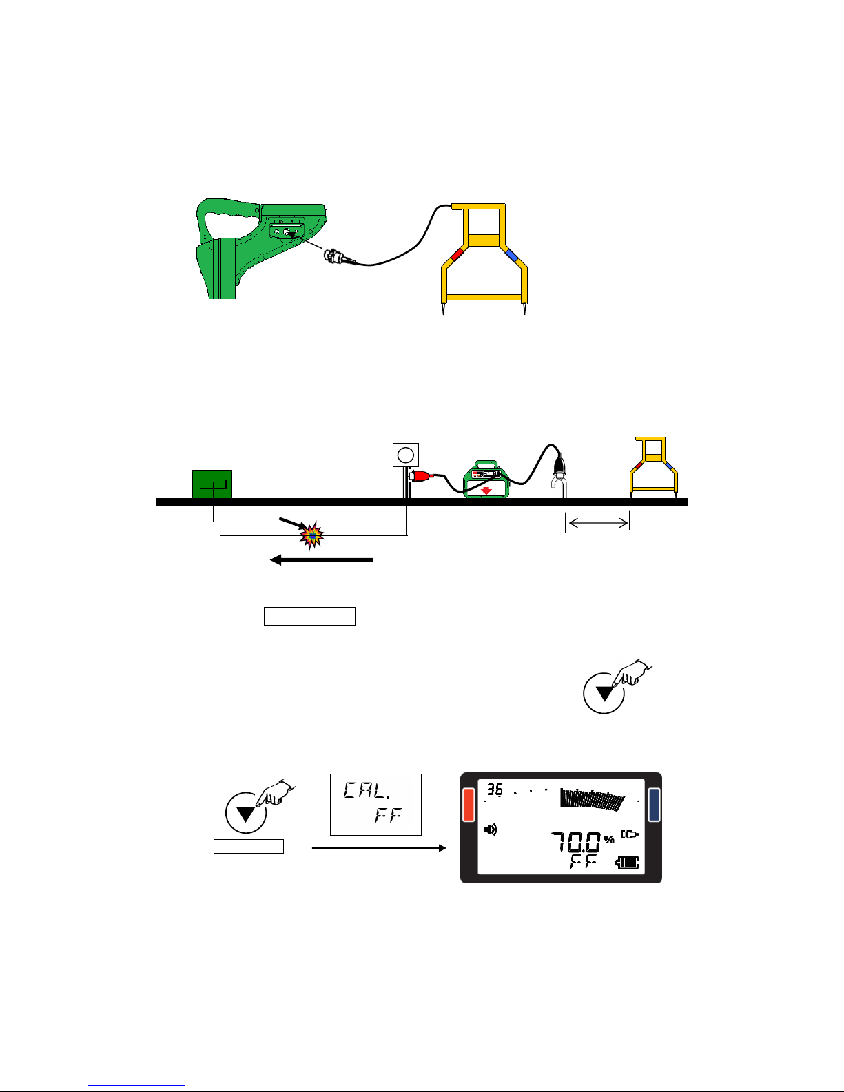
Connect the A-frame to the Receiver.
Place both legs of the A-frame in the earth with the red leg pointing at the ground stake.
Distance from ground stake should be approximately the same as the suspected depth of
the cable.
Press and hold the Gain/Select key for one second, this will adjust the sensitivity of
the Receiver and display 70.0% +/-
If the Receiver displays OVER– manually reduce the output on the Transmitter until
overload message is replaced with numbers.
Note: This will be a reference number if line has multiple faults.
Ground
Stake
Meter
Transformer
Cable Path
Transmitter
Same as depth
of the cable
Gain/Select .
A-frame
A-frame
Fault
Page 5
4
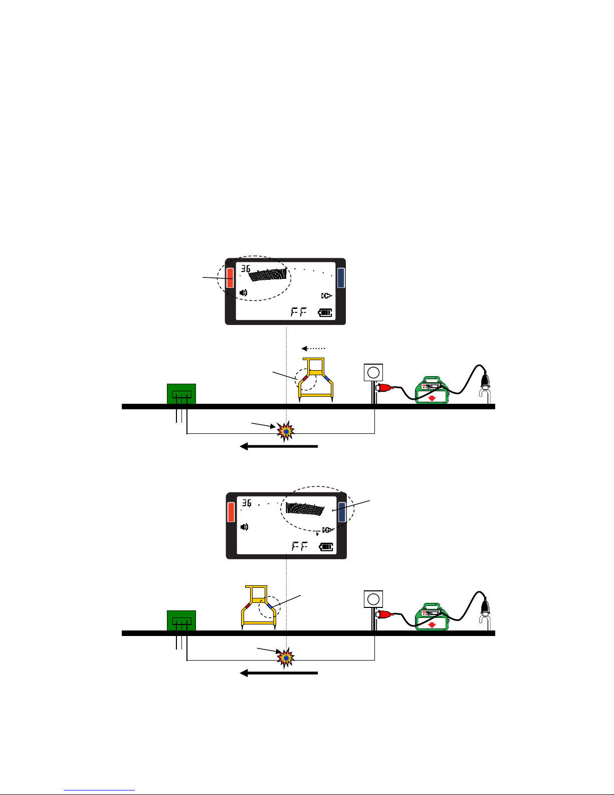
Place the A-frame in the earth parallel along the path of the cable.
The Receiver will display an arrow on the LCD.
Arrow will point towards the red or blue indicator.
The A-frame legs will be marked with a red or blue decal.
Follow the direction the Receiver is showing (Example – if the LCD is pointing towards
the red indicator and the red leg of the A-frame is pointing towards the front – walk
forward.)
Walk in this direction placing the A-frame in the earth every five to ten feet.
Note: If LCD does not display arrow or signal strength A-frame is not reading signal.
The A-frame may not be making contact with earth or signal is too weak due the distance
from the fault point or cable path. Continue walking the cable path. When the A-frame
begins to read signal the arrows and numbers will be displayed again.
When the arrow changes directions the operator has passed the fault.
Fault
Fault Pointed the Red
indicator
Red decal
Pointed the blue
indicator
Blue decal
Cable Path
Ground
Stake
Meter
Transformer
Transmitter
Cable Path
Ground
Stake
Meter
Transformer
Transmitter
Page 6
5
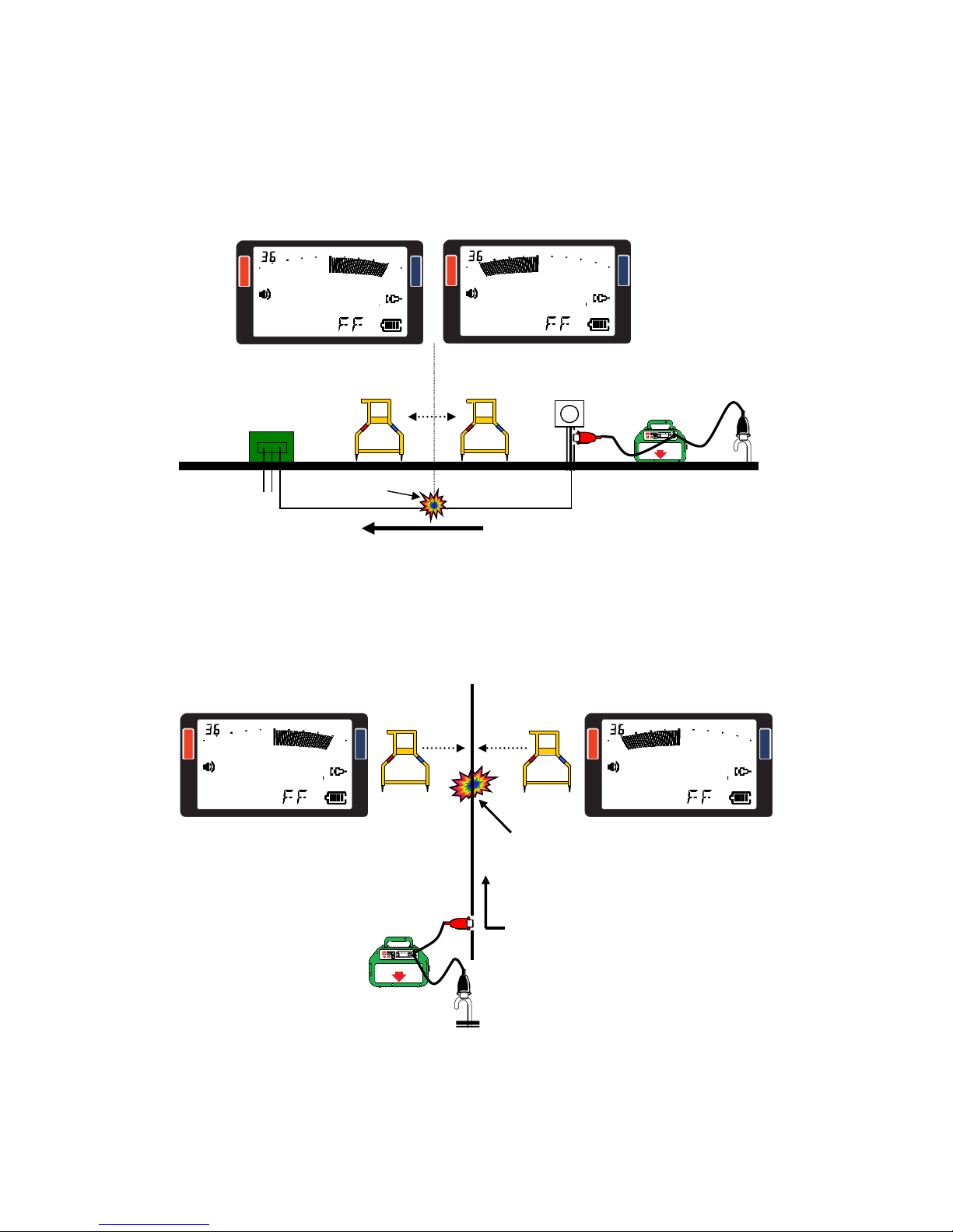
Move backwards placing the A-frame in the earth every few inches when the arrow
changes direction again you have reached the area of the fault. The fault point will be in
the center of the A-frame.
CONFIRM THE FAULT LOCATION
Turn the A-frame 90 degrees perpendicular to the cable path. Place the A-frame in the
earth and follow the direction the arrows are showing on the LCD.
When the Arrows change direction you are over the fault.
Fault
Cable Path
Fault
Cable Path
Ground
Stake
Meter
Transformer
Transmitter
Page 7
6
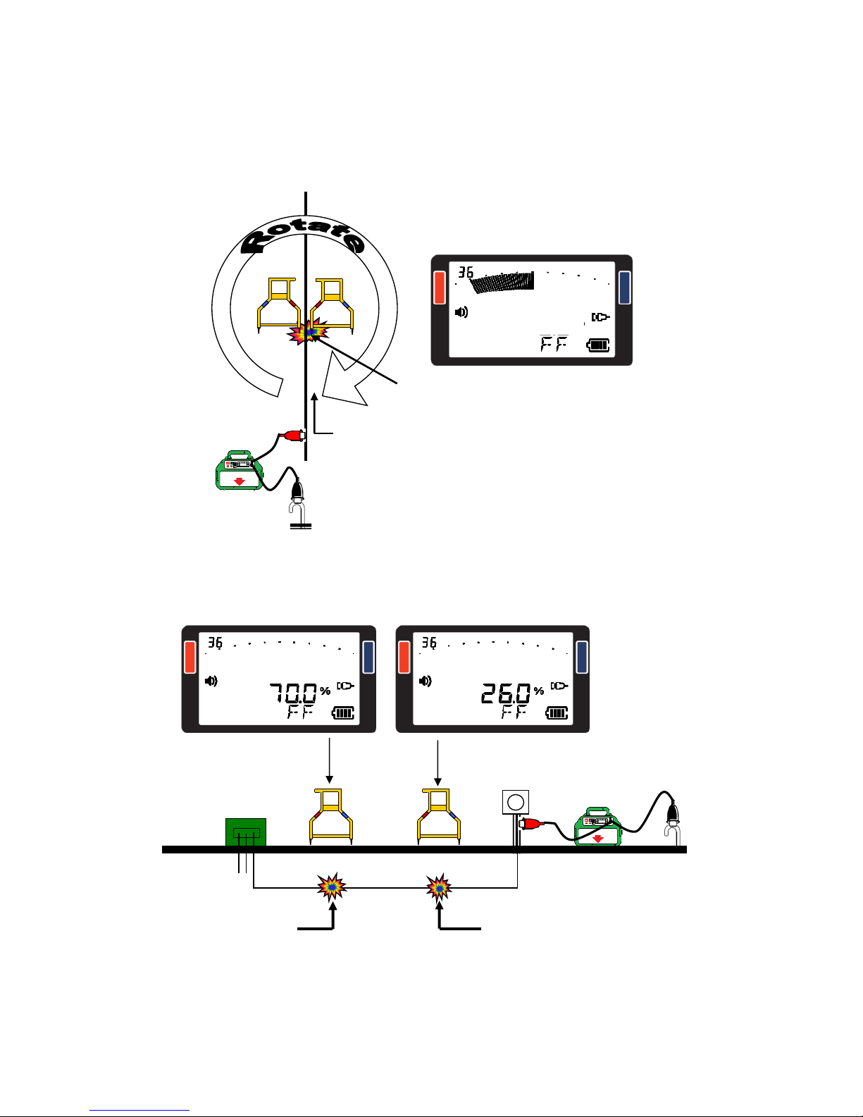
To confirm the fault place the red leg over the suspected faulted area. Pivot the A-frame
in a 360-degree circle if the indicator continually shows Red then fault is beneath the red
leg.
Multiple Faults –Place both legs of the A-frame in the ground with the red leg directly
over the fault point. With a line that has multiple faults, the fault that registers the highest
reading on the display is the fault. That needs to be repaired.
Cable Path
Fault
Ground
Stake
Meter
Transformer
Transmitter
High Resistance
Earth Ground
FAULT
Low Resistance
Earth Fault
Page 8
7
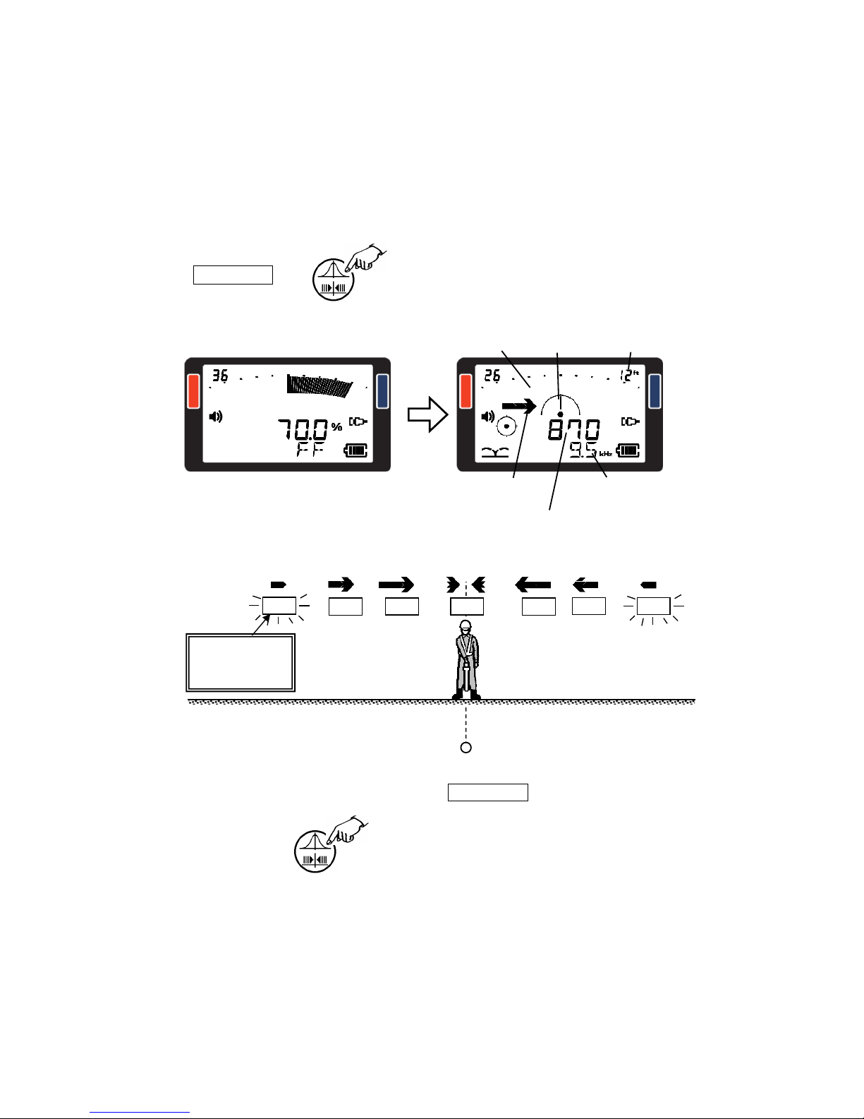
When doing the cable fault location work, the cable locating is possible.
When being connected A-FRAME, the cable locating is possible with switching the
mode to Cable locating mode.
Press Peak/Null .
Move to the direction of the arrow and measure the location of the cable.
When going back to Fault finding mode, press Peak/Null again.
The direction of
the object line.
Receiving level
No bar-graph
Yaw angle
Real time depth
Operational frequency
or
R
eal time Current
Fault finding mode
30 150
40
550
M
ove in the direction
of the arrow.
100
340 300
Cable locating mode
OUT OF RANGE
Number of receiving
level is blinked.
Object line
 Loading...