

Page 1

TN4000-5
Technical Note
Preventative Maintenance Guide
For MT4000 TWTA
April 11, 2002
Donald Surprenant 4/12/02
Engineering Date
Dave B. Marshall 4/12/02
Customer Service Date
Page 2

TECHNICAL NOTE – PREVENTATIVE MAINTENANCE GUIDE FOR MT4000 4/11/2002
TABLE OF CONTENTS
1.0 SAFETY SUMMARY............................................................................................................3
1.1 Definitions of Warnings, Cautions and Notes................................................................3
1.2 General Safety Precautions............................................................................................ 4
1.3 List of Hazards..............................................................................................................5
2.0 SCOPE....................................................................................................................................7
3.0 MOISTURE PREVENTION.................................................................................................7
4.0 MAINTENANCE SCHEDULE............................................................................................. 7
4.1 Quarterly Maintenance..................................................................................................8
4.2 Annual Maintenance .....................................................................................................8
4.3 Bi-Annual Maintenance.................................................................................................9
TN4000-5 MCL, INC. 2 of 11
Page 3

TECHNICAL NOTE – PREVENTATIVE MAINTENANCE GUIDE FOR MT4000 4/11/2002
1.0 SAFETY SUMMARY
1.1 Definitions of Warnings, Cautions and Notes
WARNING AND CAUTION statements have been strategically placed in the text to
emphasize certain steps or procedures for the protection of personnel (WARNING) or
equipment (CAUTION). A WARNING or CAUTION once provided will apply each time the
related step is repeated, regardless of the number of times the step is repeated throughout the
text. Prior to starting any task, the WARNING or CAUTIONS included in the text for that task
should be reviewed and understood.
An operating or maintenance procedure, practice, condition, statement, etc.,
which if not strictly observed, could result in injury to or death of personnel.
An operating or maintenance procedure, practice, condition, statement, etc.,
which if not strictly observed, could result in damage to or destruction of
equipment, or loss of mission effectiveness.
NOTE
An essential operating or maintenance procedure, condition, or statement which
must be highlighted.
WARNING
CAUTION
TN4000-5 MCL, INC. 3 of 11
Page 4

TECHNICAL NOTE – PREVENTATIVE MAINTENANCE GUIDE FOR MT4000 4/11/2002
1.2 General Safety Precautions
The following are general safety precautions and instructions that personnel must understand
and apply during many phases of operation and maintenance to ensure personnel safety and
health and the protection of property. Portions of this information may be repeated in certain
chapters of this publication for emphasis.
KEEP AWAY FROM LIVE CIRCUITS
Operating personnel must at all times observe safety regulations. Do not replace components
or make adjustments inside the equipment with the voltage supply turned on. Under certain
conditions, dangerous potentials may exist when the power control is in the off position, due to
charges retained by capacitors. To avoid injuries, always remove power from, discharge, and
ground a circuit before touching it. Adhere to all lock out/tag out requirements.
DO NOT SERVICE OR ADJUST ALONE
Do not attempt internal service or adjustment unless another person capable of rendering aid
and resuscitation is present.
RESUSCITATION
Personnel working with or near dangerous voltage shall be trained in modern methods of
resuscitation.
COMPRESSED AIR
Use of compressed air for cleaning can create an environment of propelled foreign particles.
Air pressure shall be reduced to less than 30 psi and used with effective chip guarding and
personnel protective equipment.
TN4000-5 MCL, INC. 4 of 11
Page 5
TECHNICAL NOTE – PREVENTATIVE MAINTENANCE GUIDE FOR MT4000 4/11/2002
1.3 List of Hazards
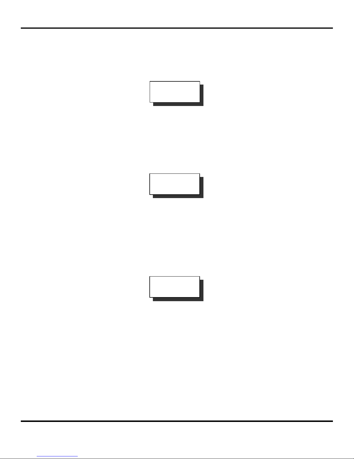
The operation of this amplifier may involve some of the following hazards; any of them could
result in serious harm to personnel if proper safety precautions are not taken.
WARNING
HIGH VOLTAGE
Lethal Voltages up to 15,000 Volts are present in this amplifier when
it is operating. USE EXTREME CAUTION when inside the unit.
Do not insert objects through air intake screen on rear of drawer.
When testing, always ground the drawer chassis.
WARNING
RF RADIATION
Exposure to RF radiation may cause serious bodily injury possibly
resulting in blindness and death. Cardiac pacemakers may be
affected. Always terminate both the RF input and RF output, even
during tests, which involve no RF drive, to avoid the RF hazard
should the TWTA oscillate.
WARNING
BERYLLIUM OXIDE
The dust or fumes from Beryllium Oxide (BeO) ceramics used in
microwave tubes are highly toxic and can cause serious injury or
death.
TN4000-5 MCL, INC. 5 of 11
Page 6

TECHNICAL NOTE – PREVENTATIVE MAINTENANCE GUIDE FOR MT4000 4/11/2002
LIST OF HAZARDS (Continued)
WARNING
IMPLOSION HAZARD
Ceramic windows from microwave tubes can shatter on impact or
crack in use resulting in injury from Beryllium Oxide dust or fumes.
WARNING
X-RAY RADIATION
High voltage tubes can produce dangerous, possibly fatal X-Rays.
WARNING
HOT SURFACES
Surface temperature of tubes and other air-cooled parts can reach
several hundred degrees centigrade.
CAUTION
The unit may be damaged by drive levels as low as -17 dBm for the
Model MT4000 depending upon the settings of the system attenuator.
Please apply RF with caution. Always terminate RF input and output
ports properly when AC power is supplied to the TWTA.
TN4000-5 MCL, INC. 6 of 11
RF OVERDRIVE
Page 7
TECHNICAL NOTE – PREVENTATIVE MAINTENANCE GUIDE FOR MT4000 4/11/2002
2.0 SCOPE
This document contains a preventative maintenance schedule for normal operating conditions
and instructions for simple maintenance tasks, which should be performed regularly. This
document also explains why it is important to keep your amplifier system well maintained and
follow basic safety precautions. This document assumes a familiarity and working experience
with high power microwave RF amplifiers.
3.0 MOISTURE PREVENTION
Where outside air is used for cooling, if the system has been shut off for any length of time, an
inspection for moisture accumulation and water buildup in the interior of the cabinet should be
performed before any attempt is made to activate the system.
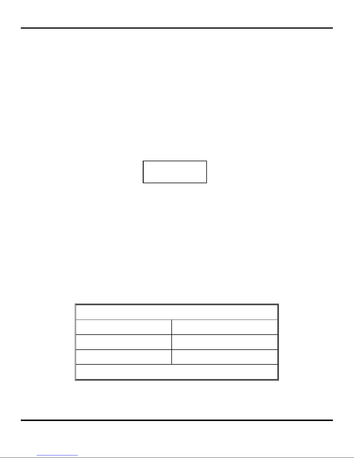
CAUTION
Do not operate this system when excessive moisture is present in the interior
4.0 MAINTENANCE SCHEDULE
The following table is showing the maintenance schedule for the MT4000. There are three
maintenance intervals broken down into separate tables. The MT4000 should be inspected to
permit early detection of wear or damage, which if properly corrected will prevent equipment
malfunction or failure. Examinations for wear, breaks, deterioration, excessive moisture,
mounting integrity and other defects should be made. If the equipment has been subjected to
severe environmental conditions, such as dust input ambient air, temperature extremes, or
excessive shock or vibration, inspections should be more frequently performed.
Every 3 months Perform items in table “A”
Every 12 months Perform items in table “A, B”
Every 24 months Perform items in table “A, B, C”
Maintenance schedule starts from date of purchase
TN4000-5 MCL, INC. 7 of 11
MAINTENANCE SCHEDULE
Page 8
TECHNICAL NOTE – PREVENTATIVE MAINTENANCE GUIDE FOR MT4000 4/11/2002
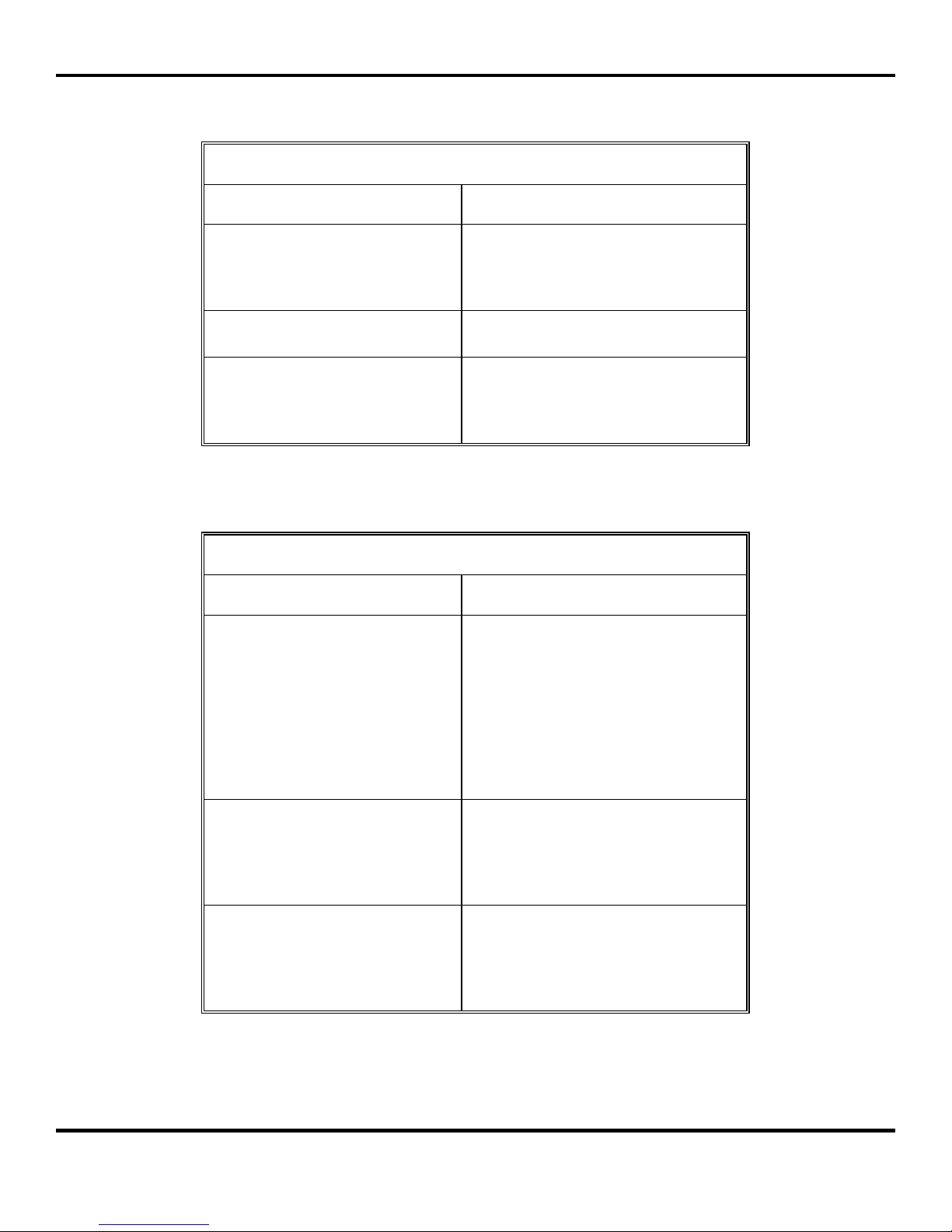
4.1 Quarterly Maintenance
MAINTENANCE SCHEDULE A
ITEM PROCEDURE
Use a dry clean cloth, a soft bristle
Front Panel Control and Meter
brush, a cloth moistened with warm
soapy water or diluted alcohol to clean
the front panel.
Connector Jacks and Plugs
Download HPA Configuration
4.2 Annual Maintenance
ITEM PROCEDURE
Chassis
Remove dust and dirt with soft bristle
brush or low-pressure compressed air.
See the Downloading Status &
Downloading Settings paragraphs of
TN4000-3 Technical Note Operation
of MT4000 TWTA.
MAINTENANCE SCHEDULE B
Turn all power off before cleaning
inside the chassis. When cleaning with
compressed air, wear safety goggles
and use clean, dry compressed air not
exceeding 25 psi. Remove top cover
and clean with lint free cloth, small
vacuum or compressed air. Use
alcohol to clean airborne residue
around HV area.
Chassis Slide
Blower
TN4000-5 MCL, INC. 8 of 11
If slide does not move freely, clean the
slide mechanism with alcohol and
apply a light coat of lubriplate no. 110
(or equivalent). Wipe off any excess
lubricant with a clean lint free cloth.
Inspect the blower and the air channel
for any potential obstruction. Use
compressed air or a vacuum to clean
the blower and the TWT heat sink
assembly.
Page 9

TECHNICAL NOTE – PREVENTATIVE MAINTENANCE GUIDE FOR MT4000 4/11/2002
4.3 Bi-Annual Maintenance
WARNING
Only a trained technician should perform this bi-annual
maintenance procedure on the MT4000
Although care has been taken in the design of the system to provide such features as an
interlock switch, high voltage points which are clearly marked, and warning labels affixed to
the system, it will be necessary to defeat the interlock switch when performing certain tests
outlined in Table C.
There are two hardware configurations under the HPA cover. Refer to the diskette that was
provided with your amplifier (each diskette is unique to each amplifier). Compare the settings
on the diskette with the current values on the amplifier display; if there is significant difference,
then a re-calibration may be necessary. If you are equipped and able to perform High Voltage
measurements, then follow TABLE C, if not, contact MCL Customer Service for assistance.
TN4000-5 MCL, INC. 9 of 11
Page 10
TECHNICAL NOTE – PREVENTATIVE MAINTENANCE GUIDE FOR MT4000 4/11/2002
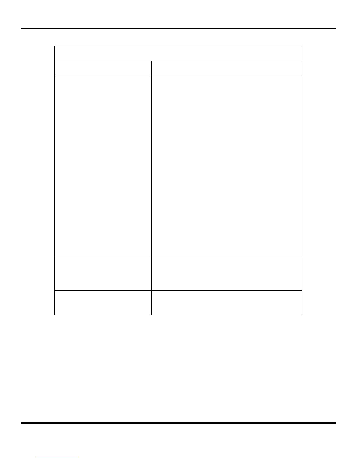
MAINTENANCE SCHEDULE C
ITEM PROCEDURE
Compare the tube nameplate value for Helix Voltage
with the display value.
For a slight adjustment (less than 100V +/-), follow
these steps:
Turn on the main breaker on the front panel.
While the HPA is in Filament Off, on the HPA
front panel, check the Helix Voltage Set Point,
and adjust Helix Voltage adjust potentiometer
until the Helix Voltage Set Point reads the
TWT nameplate value.
High Voltage Calibration
If there is significant difference of more than 100V +/-
follow the steps below:
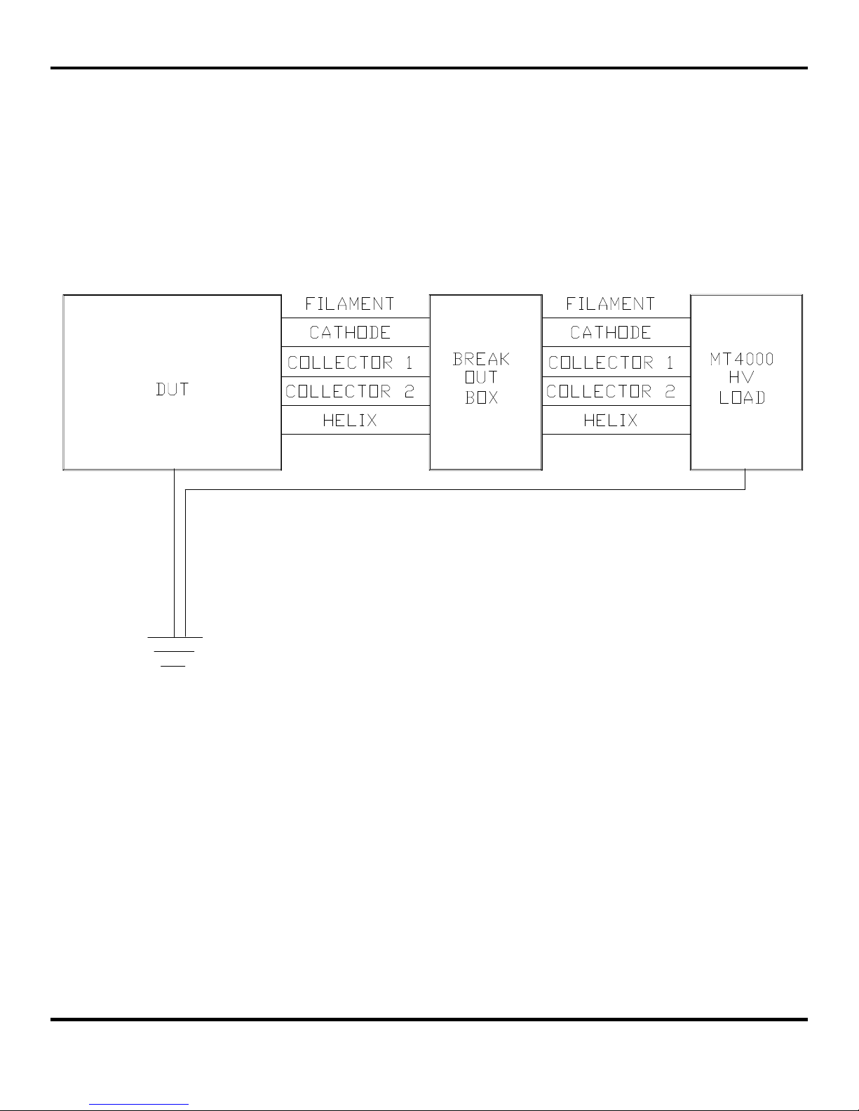
In the HPA, disconnect the tube leads from the
HV module. Connect a HV break-out box to
the HV module and then connect a MT4000
HV Load to the break-out box (see the figure
on the next page). Connect the reference of a
15kV precision divider box to the HPA chassis.
Connect the high voltage lead of the divider
box to the cathode terminal of the break-out
box.
Adjust the Helix Voltage adjust potentiometer for the
tube nameplate value.
Check the calibration of the RF meters. If calibration is
RF Calibration
Blower
required see the RF Meter Calibration Procedure
paragraph of TN4000-6 Technical Note
Troubleshooting & Customer Service Guide.
Inspect the blower and the air channel for any potential
obstruction. Use compressed air or a vacuum to clean
the blower and the TWT heat sink assembly.
TN4000-5 MCL, INC. 10 of 11
Page 11
TECHNICAL NOTE – PREVENTATIVE MAINTENANCE GUIDE FOR MT4000 4/11/2002
TN4000-5 MCL, INC. 11 of 11
 Loading...