

Page 1
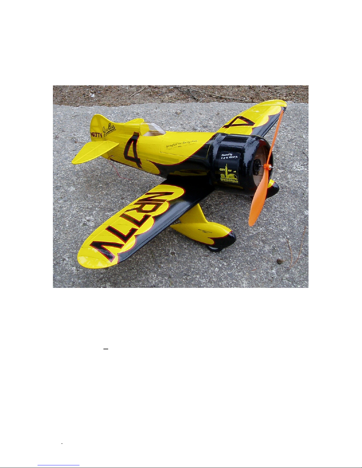
Gee Bee Z
Construction Manual
McKELLAR AERO DESIGN
Wingspan: 28”
Wing Area: 128 in²
Weight: 8.5 oz
Power: GWS IPS-A gearbox with Medusa 012-
©McKELLAR AERO DESIGN
030-4000
prop) OR small outrunner
1
brushless motor (30-40W with 8X6
Ver. 1.3
Page 2

Table of Contents
Introduction…………………………………….…………..……2
Kit contents…………………………………….……………..….2
Required to complete……………………….……………...2
General building instructions………………...………3
Building the vertical and horizontal tail………3
Building the wing………………………..………..…………..4
Building the cowl……………………………………….……..5
Building the fuselage…………………….……….……..…7
Building the wheel pants………….…………….……….17
Recommended equipment………………………………..20
Final assembly……………………………………………………21
Prepare for flight……………………………….……………22
First flight……………………………………….……………….22
Introduction
Thank you for purchasing this model kit. We have worked very hard to provide a model that
is both easy to build and fly. Please read through all the instructions before you begin
building so that errors can be avoided.
Kit Contents
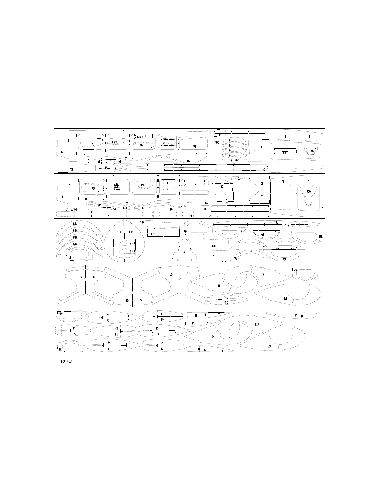
• Four sheets of laser cut 1/16” balsa
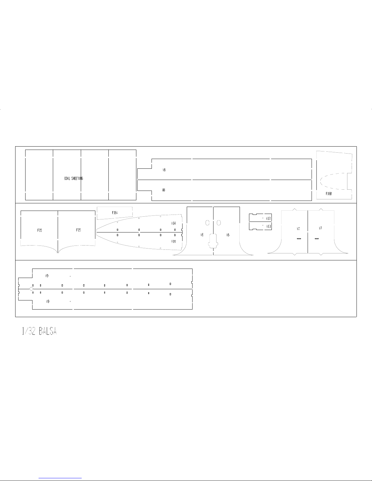
• Three sheets of laser cut 1/32” balsa
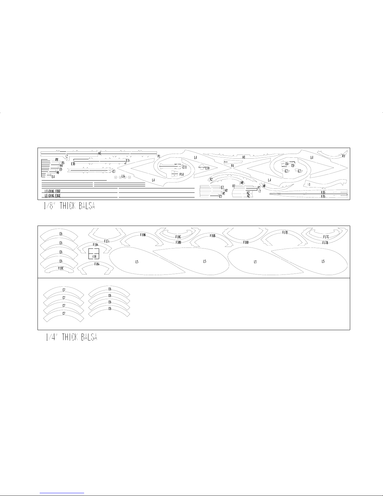
• One sheet of laser cut 1/8” balsa
• Two sheets of laser cut 1/4” balsa
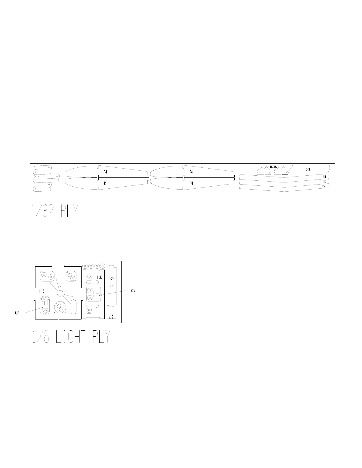
• One sheet of laser cut 1/8” light plywood
• One sheet of laser cut 1/32” plywood
• Vacuum formed canopy
• Plans
Required to Complete
• 0.032” music wire
• 0.047” music wire
• Two plastic tubes (Evergreen Plastics 3/32” styrene tubes)
• Two 1/8” diameter by 1/16” or 1/8” long rare-earth magnets
• Two Dubro Micro E/Z Connectors
• 8-32 nylon bolt
• Covering (Nelson LiteFilm or equivalent)
• Self-adhesive Velcro (can be found at most hardware stores)
• Medium and thin cyanoacralate (CA)
• 10 minute epoxy
• Three micro servos weighing 6-8g with 8-10 oz-in torque rating
©McKELLAR AERO DESIGN
2
Ver. 1.3
Page 3
• One micro receiver
• Motor: 12mm brushless motor (4000Kv) in GWS IPS-A gear box
Or a small outrunner.
• One speed control with BEC (battery elimination circuit) suitable for your motor.
General Building Instructions
• It is best to remove the parts from the laser cut sheets only as they are needed.
This will reduce any chance of confusion since some of the smaller parts are not
labelled on the actual part.
• Write the part numbers on the parts as they are removed from the sheets (only
mark the back sides of sheeting parts as ink will show thru the covering.
• Sand down any remainders of the tabs which held the parts in the sheet.
• Do not force any tabs into the slots. Enlarge the slots if the tabs are a bit tight. A
jewellers file or nail file works well for this.
• Be sure to check the fit of each part and assembly before applying glue.
• Use medium CA for all joints unless told otherwise.
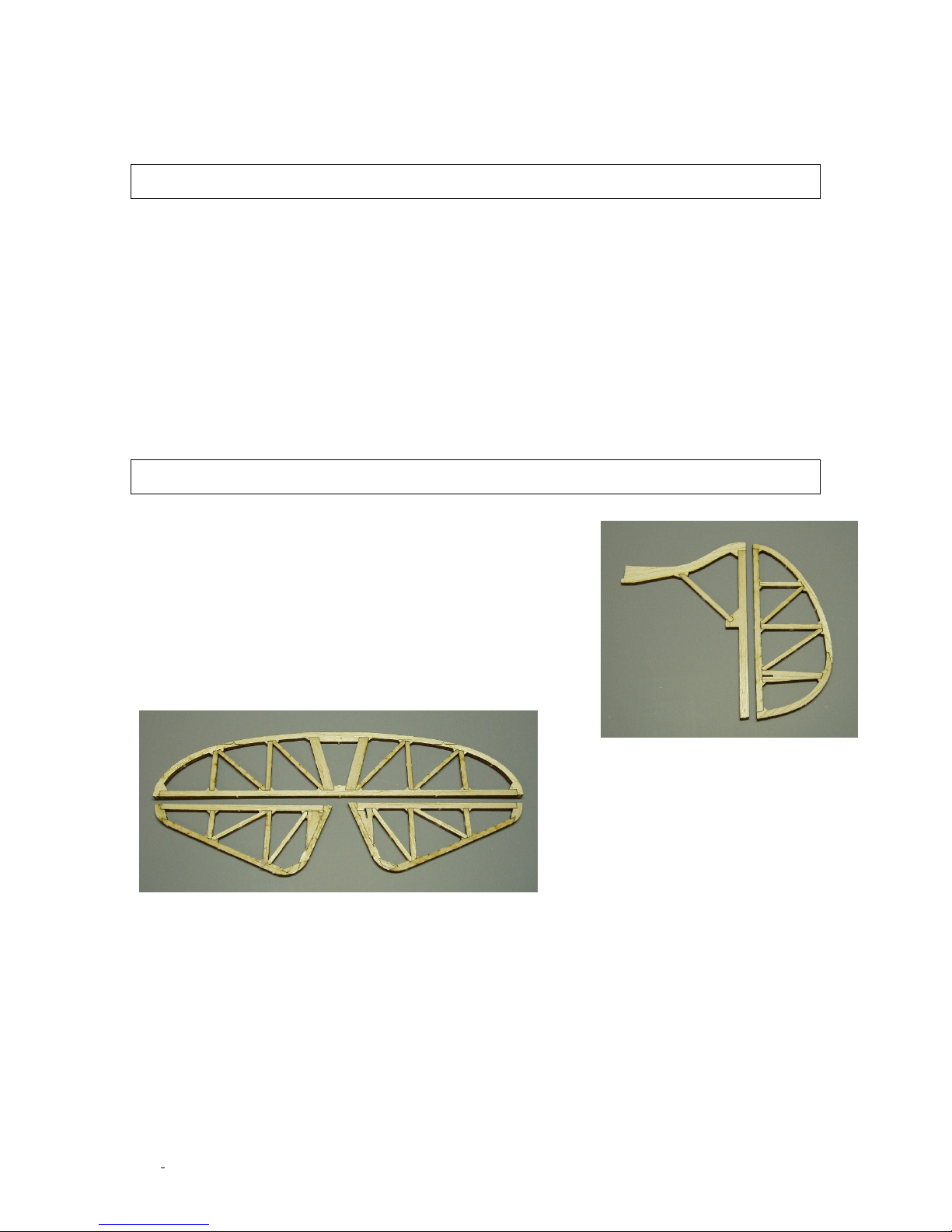
Building the Horizontal and Vertical Tail
The fin, rudder, stab and elevators are built up over the
plan. Fit all the parts in position and apply some med CA to all
the joints. Once all the glue has cured, you can remove the
fin from the building board. Lightly sand both sides so they
are flat with no lumps. The leading edge and tip should be
rounded over with a sanding block. Mark the hinge locations
and cut the hinge slots with an Exacto blade. Make the holes
for the elevator joiner wire and finally, sand the leading edge
of the rudder and elevators to a 30° angle.
©McKELLAR AERO DESIGN
3
Ver. 1.3
Page 4
Building the Wing
R1A R2
R5
R8
R7
R6
R5
R
4/R3/R4
R9
R10
W2
W1
W7
W9
W17
W12
W3
W13
W15
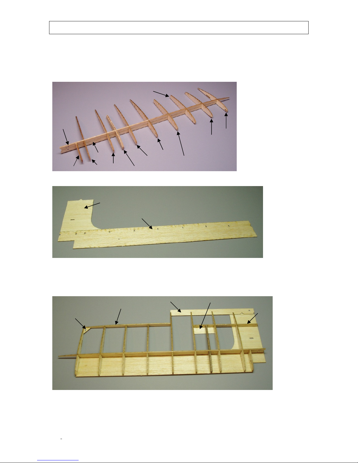
Remove all the wing ribs and spar parts from the parts sheets. Sand R3 down slightly so it is
the same thickness as the 0.047” landing gear wire. Make the R4/R3/R4 laminations and
then fit all the ribs in place on the lower spar (W1). Now carefully press the top spar (W2)
in place over the ribs. Glue WI and W2 together which a bad of CA at the join line. Do not
glue the ribs to the spar yet.
Now, glue together the lower sheeting pieces making sure that they are flat and fit well.
The spar/rib assembly is now fit in place making sure that all the rib tabs fit in the sheeting
slots. Once everything is fitting nicely, apply CA. There is no need to apply glue to the whole
joint. A few dabs will work fine. Remember, too much glue adds weight!
©McKELLAR AERO DESIGN
4
Ver. 1.3
Page 5
W6
W8
R11B
W10
W15
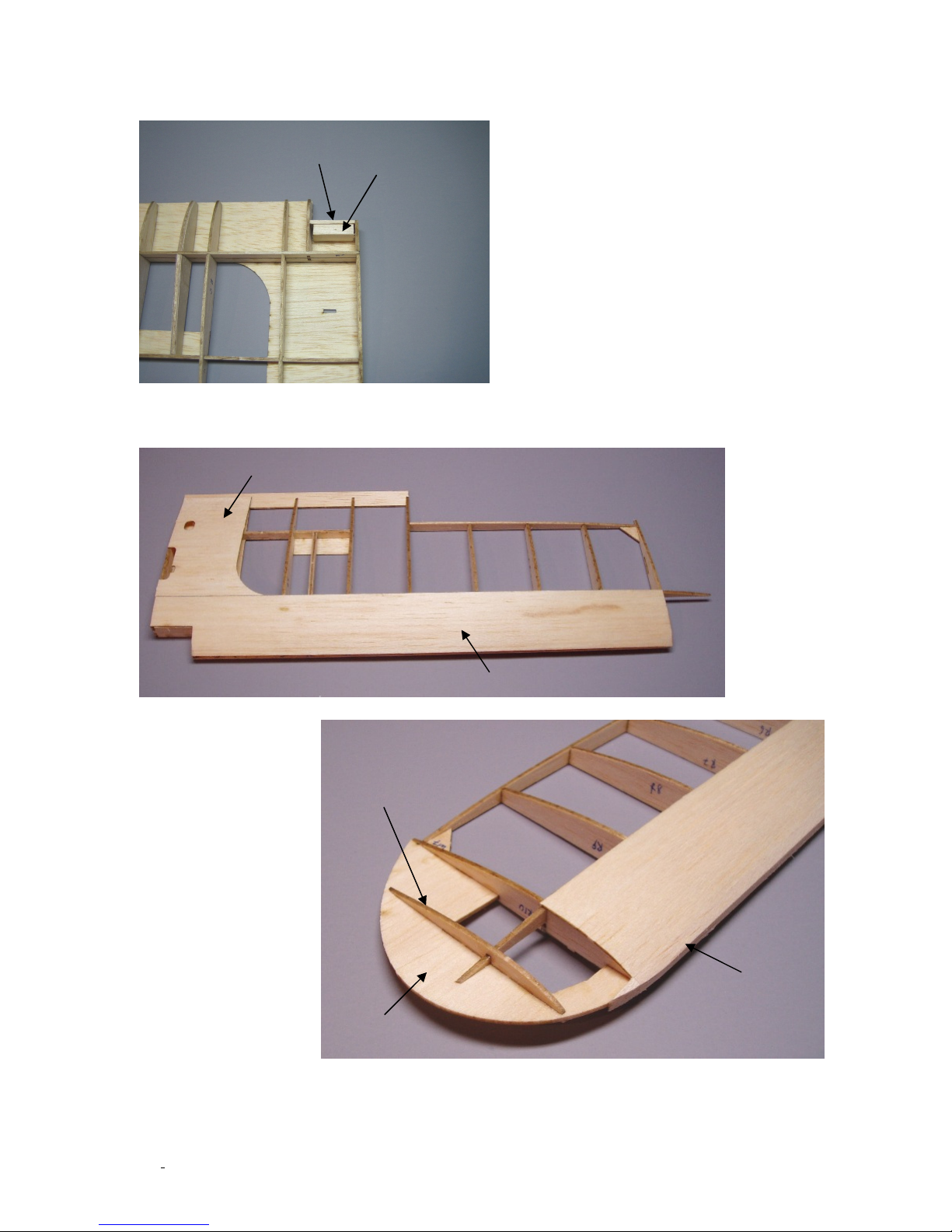
Glue the root ribs in place and be sure to glue W18, W11 and R14 in both wings before
applying the top sheeting. Use the aileron torque rod to line up R14 before gluing it.
Now, take the spar joiners (W4&W5) and test fit them in place. When you are happy with
the fit remove them and glue the top sheeting in place making sure there is no twist in the
wing.
Sand the leading edge
sheeting flush with
the ribs and glue on
the leading edge
(W15). Next, glue the
wing tip in place along
with the last wing rib
(R11B and R11A). Now
sand the leading edge
round and sand the
trailing edge of W12
and W15 down to
follow the contour of
the wing ribs. Use
some masking tape on
The wing ribs to
protect them during this stage.
©McKELLAR AERO DESIGN
5
Ver. 1.3
Page 6
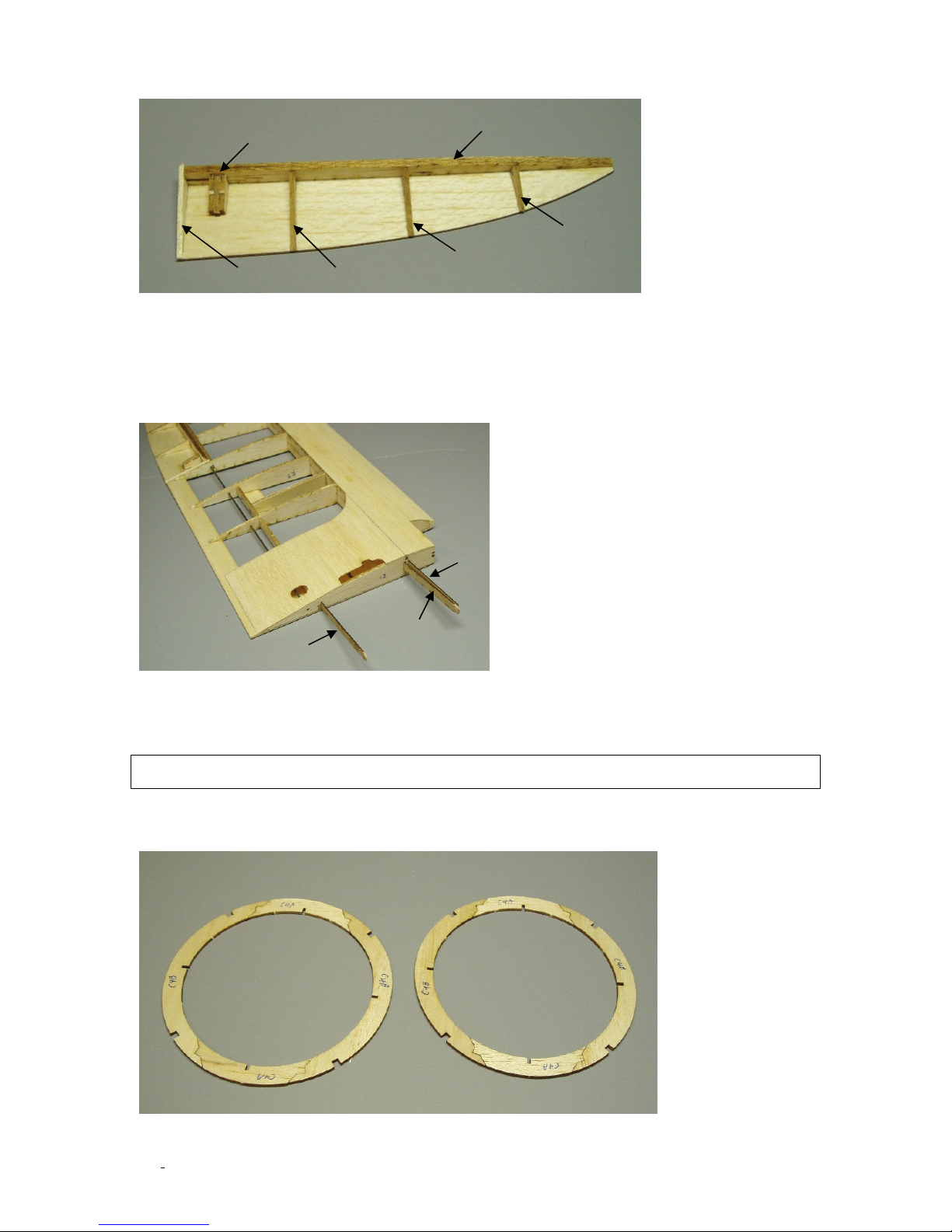
W16
R9B
R8B
R8C/R8D/R8C
W5
W4
W4
R7B R6B
The ailerons are pretty simple, just fit all the parts in place and apply some CA to the
joints. Sand the top side of W16 so that is follows the profile of the aileron ribs. Again, use
masking tape on the ribs to protect them. The final step for the ailerons is to sand the
leading edge into a V shape centered on the hinge line. This bevel only needs to be about 25°
on either side of the hinge line. This bevel will allow the ailerons to pivot about the hinge
line.
Sand the leading edge of the wing panels to the final shape and then test the fit of the
wing joiners (W4 and W5) in both wing panels. Glue the joiners in one panel and let cure.
Finally, glue the two wing halves together at the root rib and wing joiners.
Building the Cowl
Start the cowl by building the two rings made up from C4A and C4B parts. These two rings
are identical.
©McKELLAR AERO DESIGN
6
Ver. 1.3
Page 7
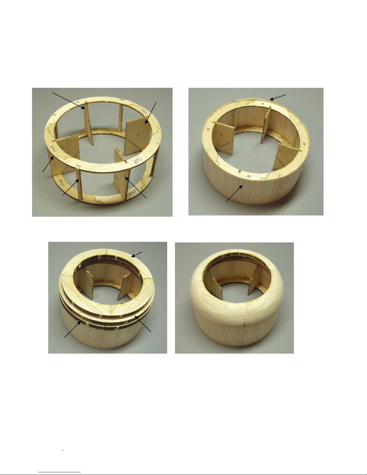
C3
C1
C1
C2
1/8” square
Cowl sheeting
Overhang
C8
C7
C6
Now, pin one cowl ring to your building board and fit the cowl rings together with the parts
C1, C1, C2 and C3. Use a square to make sure the ring edges line up and apply glue to the
joints. Now, fit in place the 1/8” square stock that has been cut on the 1/8” balsa sheet.
Make sure these sticks are the correct length before gluing in place.
The cowl sheeting is installed next. Note that this sheeting will overhang C4A/C4B ring a
little. The cowl can be removed from the building board after the sheeting is applied.
Now, flip the cowl over, cut off the building tabs on C1, C2 and C3 and glue on the ¼ balsa
rings and then sand to shape. Take your time and you will end up with a nicely shaped cowl
©McKELLAR AERO DESIGN
7
Ver. 1.3
Page 8
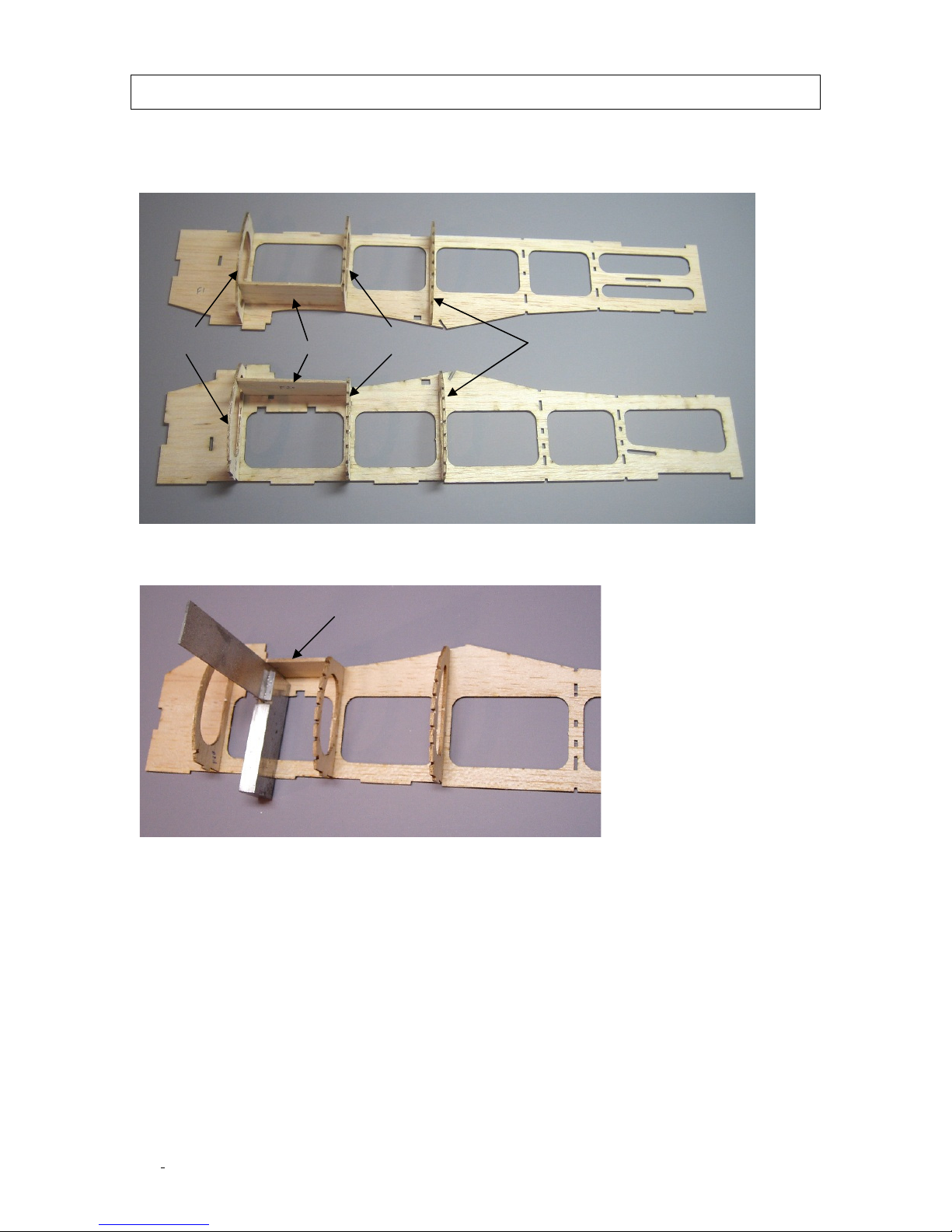
F2
F1
F6B F8B
F20
Building the Fuselage
Start with the fuselage sides. F2 is the right side and F1 is the left side. Note that F2 is
shorter than F1 due to the right thrust built into the firewall. Make sure you glue the
formers on the correct sides and double check before gluing in place.
Fit F20 in place between F6B and F7B and glue in place using a square to ensure it is
perpendicular to the fuselage side.
©McKELLAR AERO DESIGN
8
Ver. 1.3
Page 9
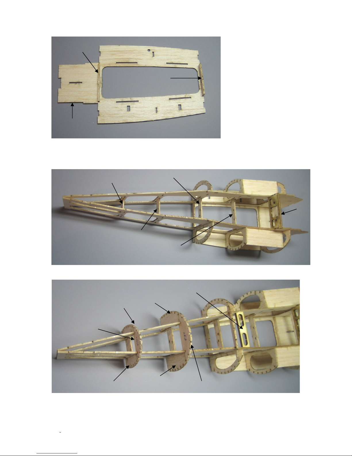
Place F6G and F8E in place on F4 and glue in place. Be sure that you glue these on the
F10D
F9D
F8D
F7D
F6D
F4
F6G
F8E
Short side
F10C
F9B
F10B
F10B
F22
F9C
F9B
correct side of F4.
Fit the fuselage sides in place on F4 and glue in place. Now fit the center former pieces
shown in the photo below. Check the plan for proper orientation of these parts. Use a square
to make sure the aft ends of the fuselage sides (F1&F2) are perpendicular to the bench.
Now, fit the aft former sides and bottoms as well as the light ply wing bolt plate (F22)
©McKELLAR AERO DESIGN
9
Ver. 1.3
Page 10
F9A
F10A
Fin Assembly
1/16”X1/8” balsa
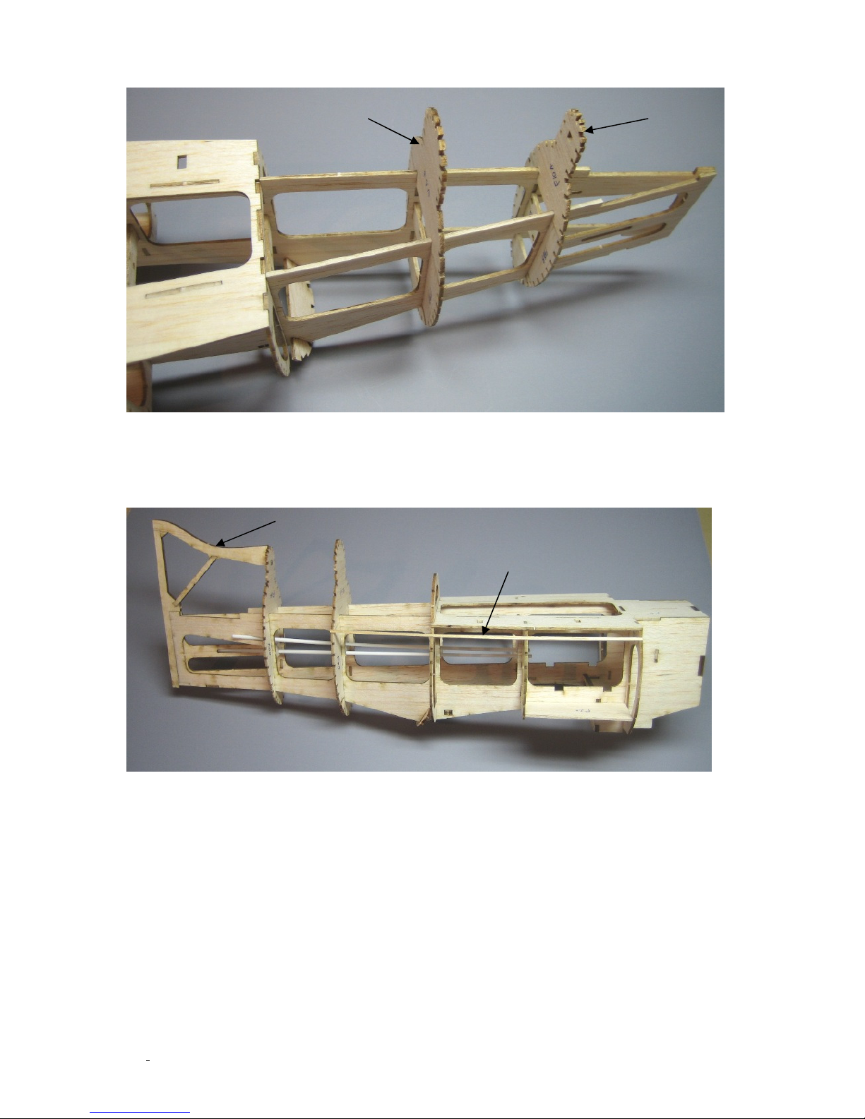
The rear top formers are now glued in place.
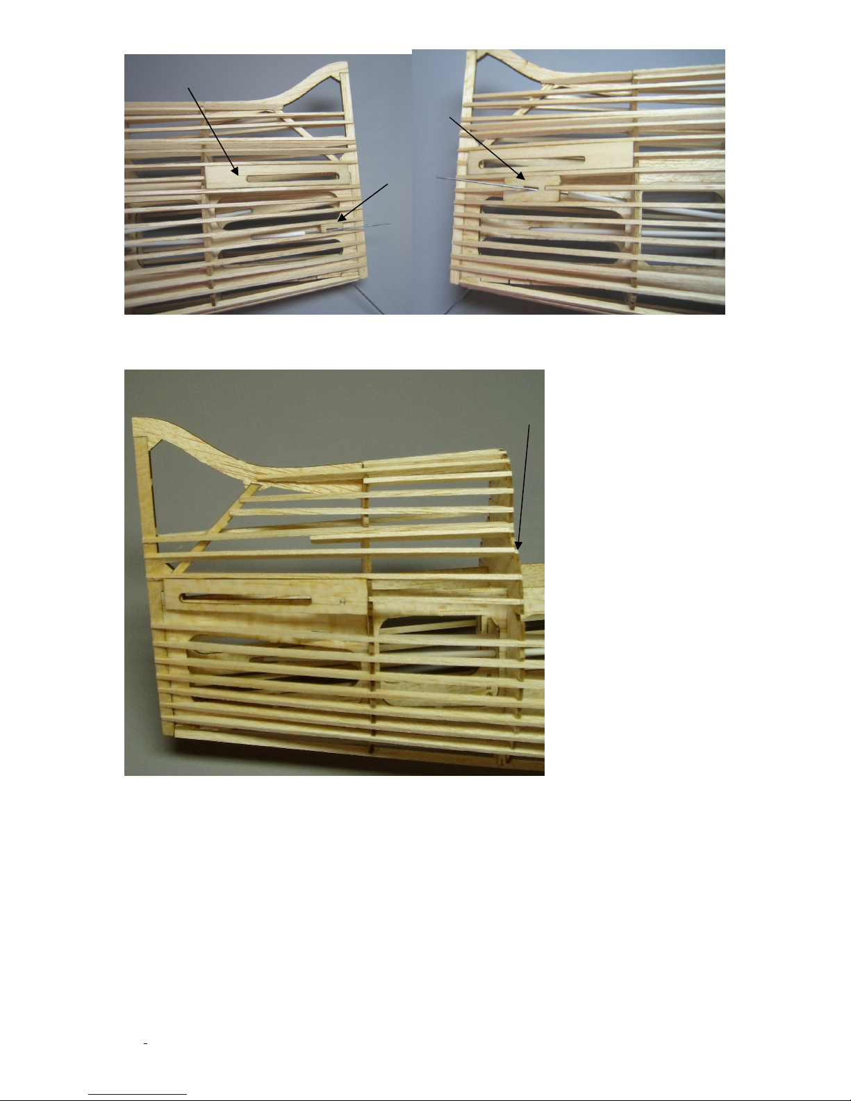
Fit the fin assembly in place making sure it lines up well with the after end of the fuselage
and glue in place. This is when you will need all those 1/16”X1/8” stringers. Fit the first
stringer in place as shown below. Note that this stringer will be flush with the former edges
as it supports sheeting. Now is a good time to install the plastic tubes for the pushrods.
Take a good look at the photo in on the next page for the stringer installation around the
cockpit. The top two stingers point out are to support the cockpit sheeting. The front end
fits in notches but the rear end is just but glued next to the slot in F9A
©McKELLAR AERO DESIGN
10
Ver. 1.3
Page 11
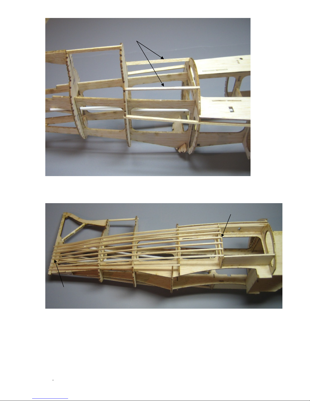
Stick buts up to former F9A flush with edge. This will support
Taper this end
Sand these ends flush
sheeting. All other stringers fit in slots.
Continue on with the other stingers and sand a taper on the rear end of the stringers. Note
that the forward end of the stringer must be sanded down flush with the edge of F7B so
that the sheeting will lie flush with the surface of the stringers.
©McKELLAR AERO DESIGN
11
Ver. 1.3
Page 12
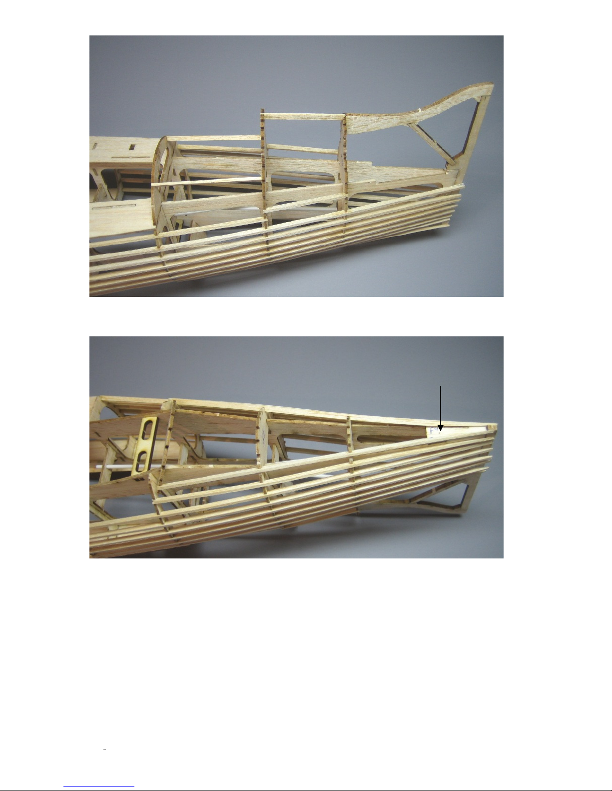
Once all the side stringers are applied it is time to install the wire tailskid. Then the belly
stringer can be glued in place. You will have to taper the back end of them so they all fit.
Wire skid goes here
Note: hole pre-cut for wire
Next, you must fit the wing in position and drill two 1/8” diameter holes through the two
pre-cut holes in F6D and into the wing. These holes are for the 1/8” dowel used to secure
the front of the wing. Fit the dowels (1/2” long) in place so they are just a little proud of
F6D, remove the wing and glue these dowels in place with thin CA.
©McKELLAR AERO DESIGN
12
Ver. 1.3
Page 13
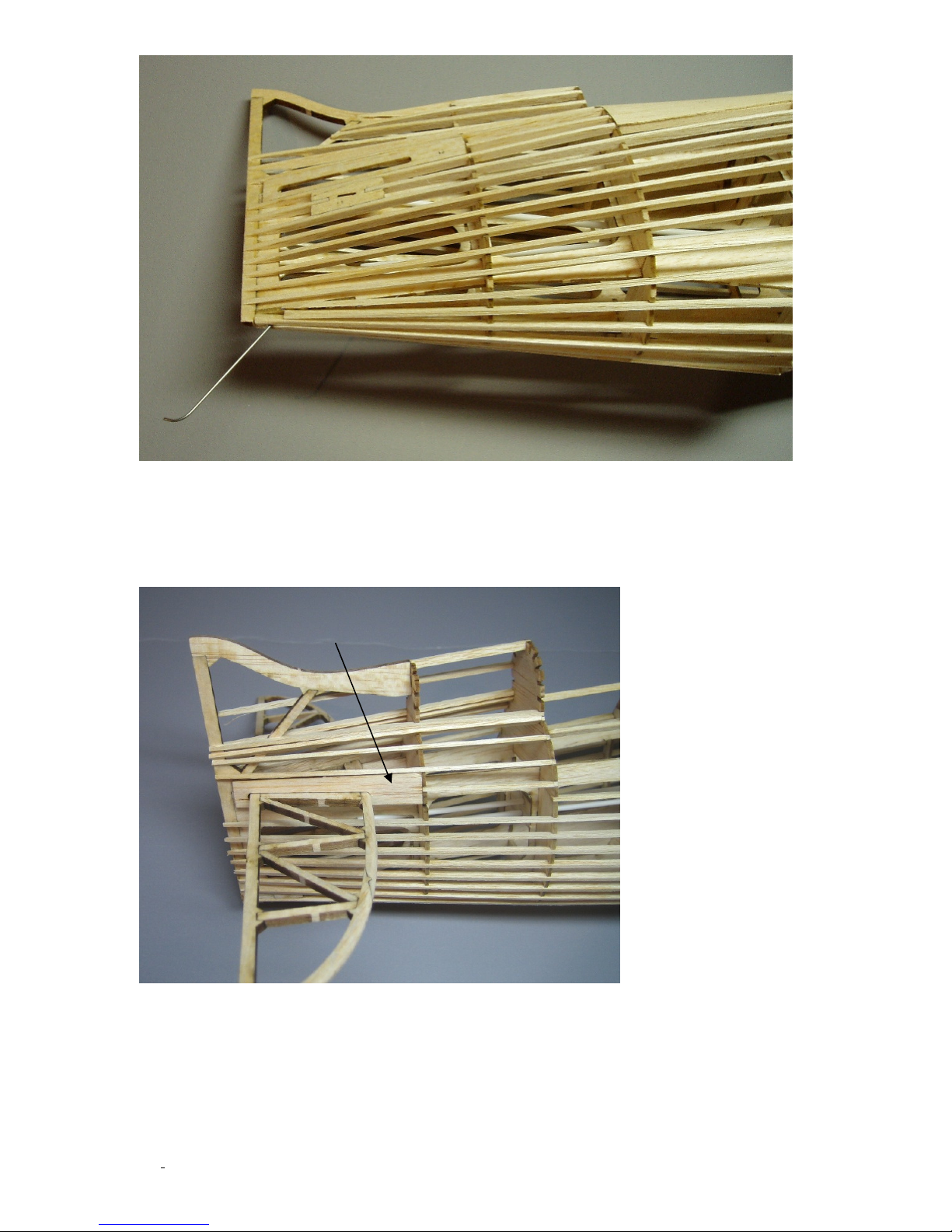
F12
Next, the fairing strip (F12) that goes around the stab is installed. The best way to do
this is to temporarily fit the stab in place and use it to line up F12. This may take a little
sanding to get a good fit but take your time and it should come out well. Now install the
pushrod fairings making sure you put them on the correct side. Use a 0.032” wire to line
them up in the correct location as shown in the second photo on the next page.
©McKELLAR AERO DESIGN
13
Ver. 1.3
Page 14
F12
F14
F13
Notch to sheeting
The photo below show the finished stringers on the top section of the fuselage. Please note
which stringers need to be notched to the edge of the former for the sheeting.
It is now time to start sheeting the fuselage. First step is to glue F16A and F16B together.
This is the sheeting that will go over the cockpit area. The dashed lines are to aid cutting
out the cockpit hole later on.
©McKELLAR AERO DESIGN
14
Ver. 1.3
Page 15
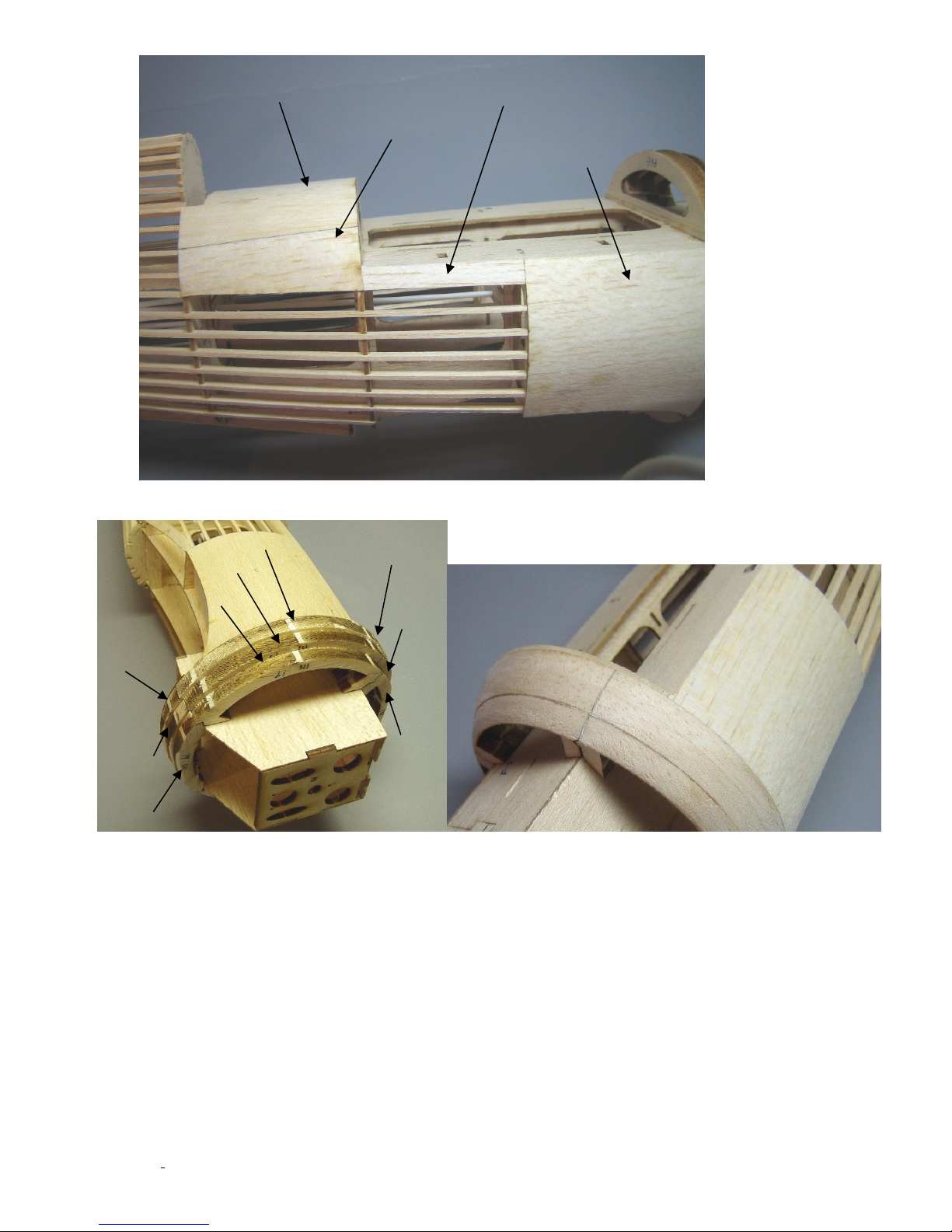
F16B
F16A
F15
Scrap 1/32” balsa
F17B
F18B
F19B
F17A
F18A
F19A
F17C
F18C
F19C
Sanded to sh
ape
The front nose rings are now glued on and sanded to shape
Now take the wing and fit in place on the fuselage. Use a 3/32” drill bit to drill thru the top side of the
wing using the bolt hole in F22 as a guide. Now enlarge these two holes with a 9/64 drill bit. Take W17 and
cut threads in the hole using a 6-32 tap. When finished, apply some thin CA to the threads and let cure.
This will harden the threads so they last longer. Now fit the wing back in place and use the 6-32 nylon bolt
and W17 to bolt the wing in place. When your happy with the fit of everything, use some epoxy to glue W17
to the wing. Be sure you don’t glue the bolt in place. Some petroleum jelly on the threads will help prevent
this. While the wing is attached, the belly formers (F8C, F7C, F6C) can be installed along with the central
stringer. Remove the wing and add the remaining belly stringers (all 1/16”X1/8”)
©McKELLAR AERO DESIGN
15
Ver. 1.3
Page 16
W19
F8C
F6C
F7C
F5
F8F
F6A
F7A
F23
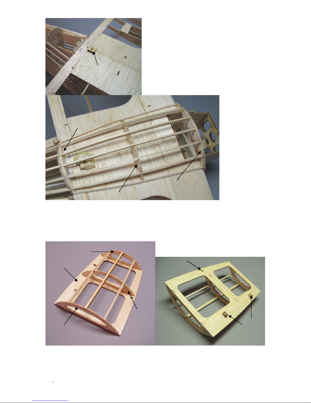
The battery hatch is built next. Note that you must sand down the edges of F5 so that it
follows the contour of the formers before you apply the sheeting. The central stinger is
1/8” square balsa from the strips cut in the 1/8” thick parts sheet. The other two stringers
are 1/16”X1/8” balsa. Check the fit of the hatch before gluing the F23 clips in place. When
the fit is good, glue both F23 in place.
Hole for
magnet
©McKELLAR AERO DESIGN
16
Ver. 1.3
Page 17
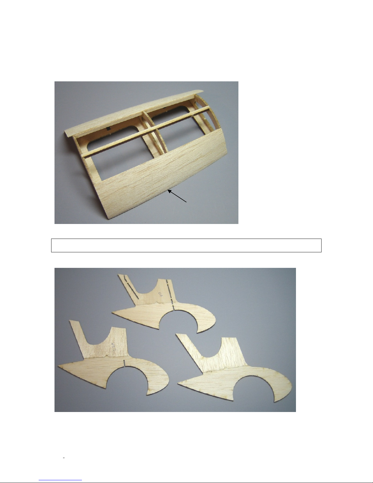
Apply the 1/32” balsa sheeting to the hatch in four sections, one between each stringer.
L1A
L1B
L3A
L3B
L2A
L2B
There is a slight compound curve to this hatch so one or two sheets will not work. The
sheeting is cut from the extra wood on the 1/32” balsa parts sheet. Glue the sheeting to F5
first. This will keep the hatch from warping as you continue sheeting. Once the sheeting is
done you can glue the 1/8” diameter magnets into the pre-cut holes in F5 (hatch) and F4
(fuselage). Make sure these magnets are oriented so that they will attract each other or
the hatch will not close!
Glue this edge
first
Building the Wheel Pants
The final step is to build the wheel pants. First, glue the inner parts together.
Now, make up the wire gear legs using the drawing as a pattern. When that is finished glue
together the L1A/B and L2A/B parts. Next, remove the tabs from the slots in L1A/B clean
©McKELLAR AERO DESIGN
17
Ver. 1.3
Page 18
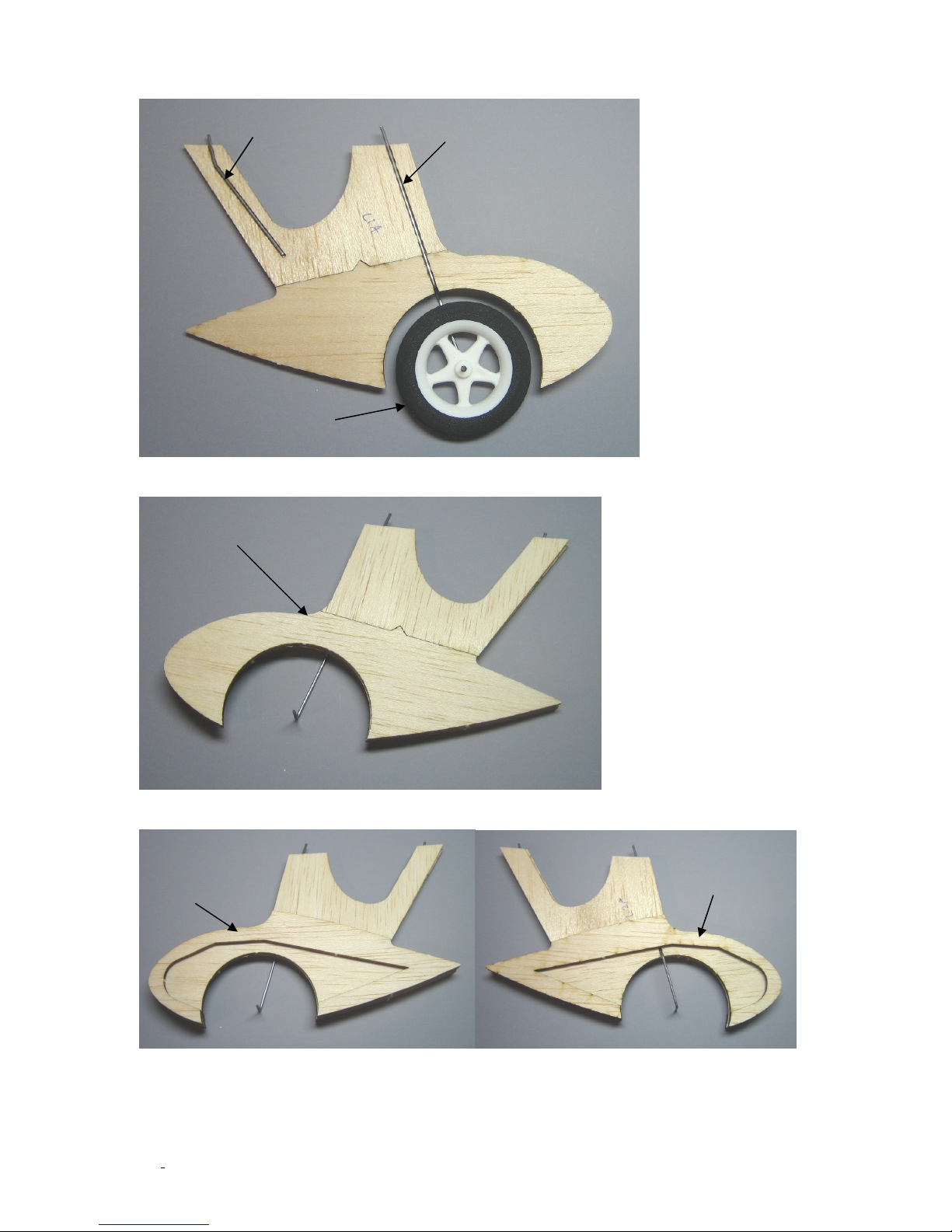
the wire gear legs well and glue in the slots. Use the wheel to make sure the main gear wire
Main gear wire
Rear gear wire
2” wheel
L3A/B
L4
L4
is located correctly before gluing.
Now glue L3A/B onto L1A/B so that L1A/B is sandwiched between L2A/B and L3A/B.
Glue L4 on both sides of the landing gear assembly.
©McKELLAR AERO DESIGN
18
Ver. 1.3
Page 19
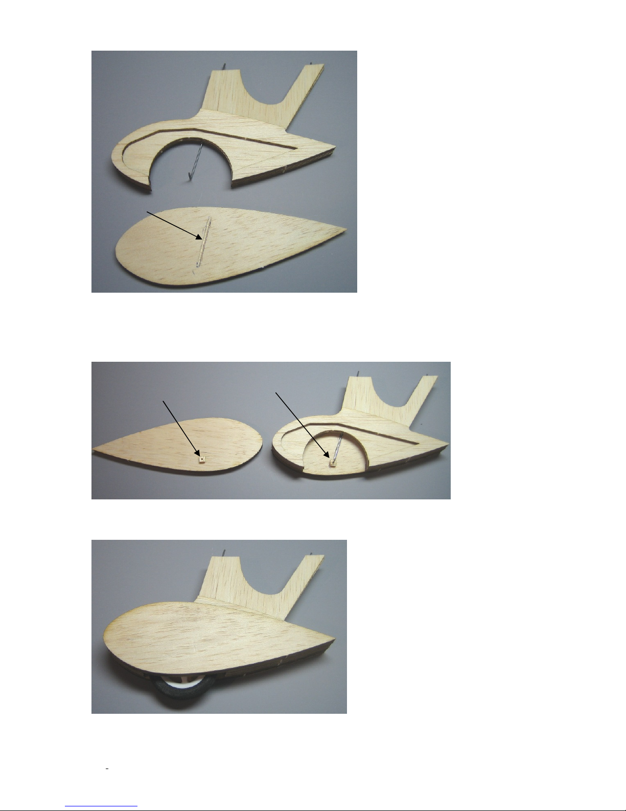
You must make a groove in one L5 so that the wire leg will fit in it. Then glue in place.
L5
Groove
L6
L6
The L6 wheel spacers may need to be sanded down a little depending on the width of you
wheel. These will keep the wheel running in the center of the pant. Apply thin CA to the
surface of L6 once they are glue in place. This will harden the surface and keep the wheel
from wearing them down.
Glue the final L5 part in place and now you can start carving and sanding. Take your time
and it should turn out well.
©McKELLAR AERO DESIGN
19
Ver. 1.3
Page 20
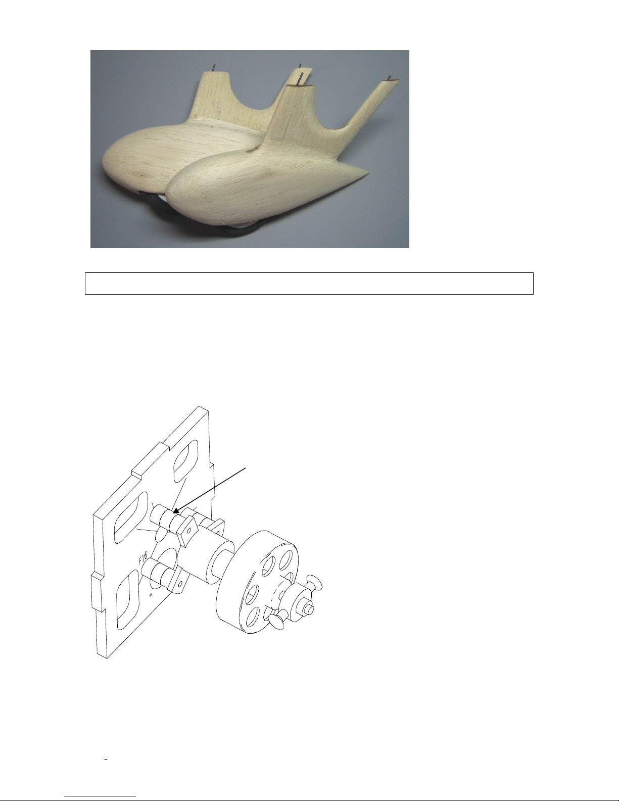
Finished wheel pants ready for covering.
PLY DISKS
Recommended Equipment
The prototype uses the Medusa Research MR-012-030-4000 in the GWS IPS-A gearbox
(5.9:1 ratio) with an 8X6 prop and 300 mah 3S (11.1V) lipo battery. This combination
provides very good power and is quite light. A small outrunner style motor would work well
for this model and the firewall has center lines etched in place to help locating it. There are
small ply disks included on the 1/8” ply sheet to help in adjusting the distance of the motor
depending on what you choose. Be sure to use mounting screws that go all the way through
the disks and into the firewall.
Servos used are the GWS Pico servos but anything in that size and power range will work. A
short antenna (base loaded) is recommended since this model since it is so short.
©McKELLAR AERO DESIGN
20
Ver. 1.3
Page 21
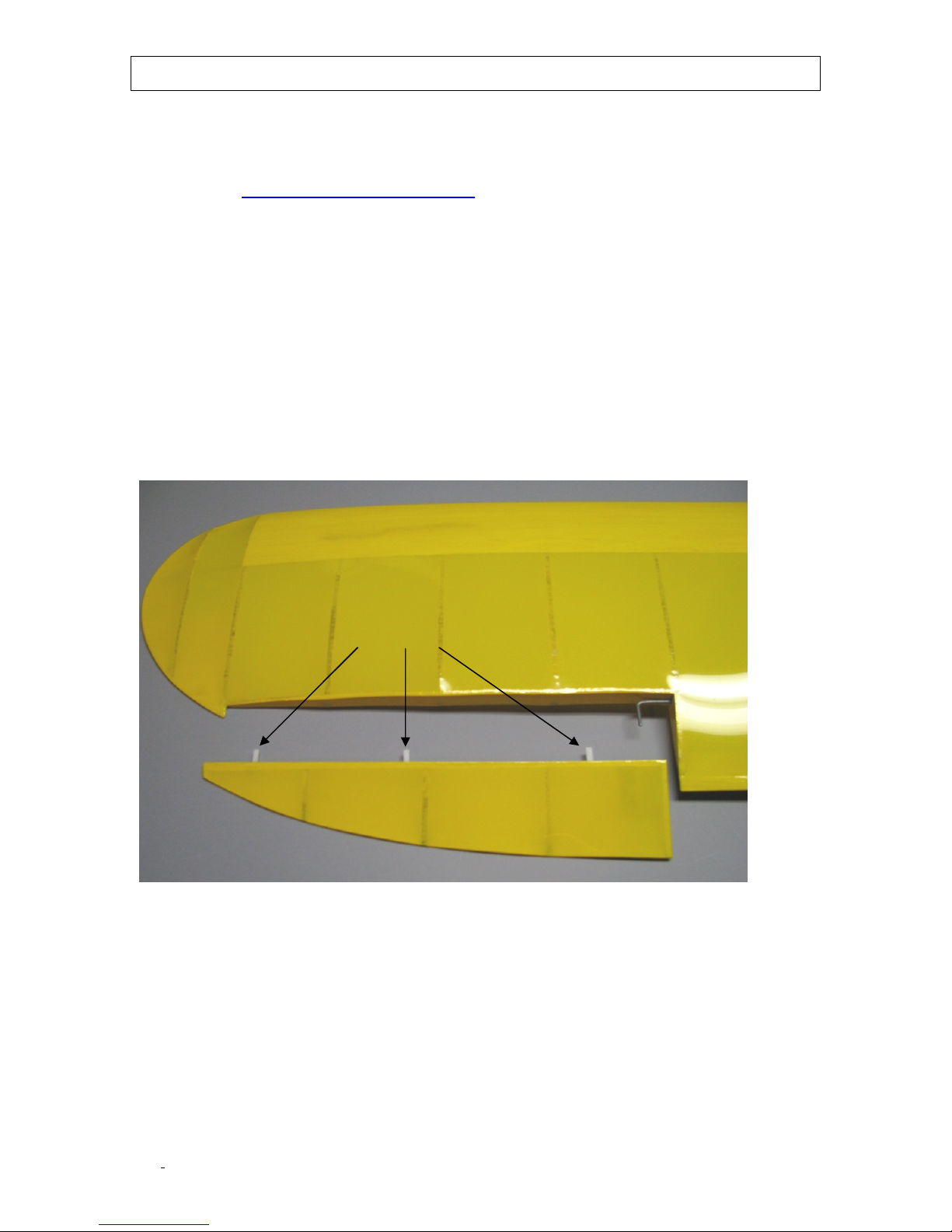
Final assembly
CA HINGE
I used Nelson Litefilm to cover the model but you can use whatever light weight covering
you prefer. A full set of vinyl graphics including all the wing and fuselage scallops and
markings are available from Callie Graphics in Albuquerque, NM. You can contact them via
their website http://www.callie-graphics.com/ or by phone at 505-293-2922. I highly
recommend this graphics package as they are very high quality and really make the model
stand out.
If you are using a film covering and the graphics package most of the plane will be covered
in yellow with only the cowl, belly section on wing and forward rim on fuselage covered in
black.
After all the covering is complete you can install the aileron torque rods, control horns and
ailerons. For control surface hinging use standard CA type hinges and cut strips of about
1/16” width. Fit the aileron torque rod in place and slip the control horn over the torque
rods. Use epoxy to glue the horns to the torque rod. Now fit the hinges in the aileron and
apply epoxy to the torque rod slot in the ailerons. Fit the ailerons in place making sure they
are centered and apply some thin CA to the hinge strips. Now, take some small spring clamps
or cloths pins and lock the ailerons flush with the wing. Line up the control horns and set
aside to cure.
©McKELLAR AERO DESIGN
21
Ver. 1.3
Page 22
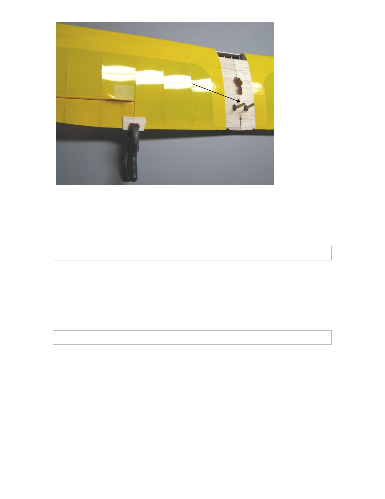
AILERON CONTROL
HORNS
Now glue the wheel pants in place by applying some glue in the slot for the wire legs. Use
epoxy for this and make sure the legs are set at the correct angle. The canopy is glue on
with canopy glue once it has been trimmed to fit. Finally, mount the motor and glue in place
the cowl.
Install the servos, pushrods and battery tray F21 between F6D and F8D. Use Velcro on the
battery tray and batteries to keep the batteries in place.
Prepare for flight
Support the wing at the location shown in Appendix B and place the receiver, speed control
and battery in position so that the plane balances level. You should be able to achieve this
balance point by shifting the battery fore and aft. Do not fly the plane with the balance
point further aft than the indicated range. A tail heavy plane is unstable and extremely
difficult to fly.
Set the control throws as shown on the plan sheet and take off using the low rates.
First flight
Be sure to do a range check before the first flight to make sure the radio is operating
properly. Check once again that the control surfaces are moving in the correct direction
when the transmitter sticks are moved. Hand launching is not recommended with this plane.
Use a good surface like pavement to take off from. Once airborne, get a feel for the plane
and try a few approaches to get ready for the landing. Keep a little bit of power on until
just before touchdown for a smooth landing. I hope you will have many enjoyable flights
with this new plane!
©McKELLAR AERO DESIGN
22
Good flying!
Ver. 1.3
Page 23
Page 24
Page 25
Page 26
 Loading...