

Page 1
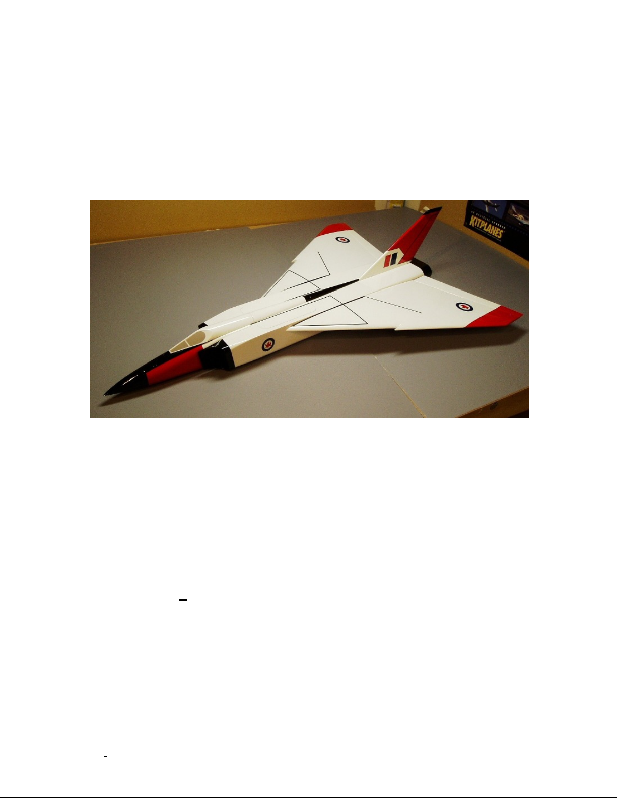
CF-105
Avro Arrow
Construction Manual
McKELLAR AERO DESIGN
Wingspan: 19.17”
Wing Area: 180 in²
Length: 27.9”
Weight: 13-14 oz
Power: Speed 400 or
100-120W brushless
©McKELLAR AERO DESIGN
1
Ver. 1.2
Page 2

Table of Contents
Introduction…………………………………….…………2
Kit contents…………………………………….………….2
Required to complete……………………….………….3
General building instructions………………...………3
Building the fin……………………………………………3
Building the wing………………………..………..…….3
Building the nose and intake nacelles…….……..5
Building the fuselage…………………….……….……7
Building the canopy and spine…………….……….10
Final assembly……………………………………………11
Prepare for flight……………………………….……….12
First flight……………………………………….…………12
Introduction
Thank you for purchasing this model kit. We have worked very hard to provide a model that is
both easy to build and fly while giving spirited performance on modest power. Please read
through all the instructions before you begin building so that errors can be avoided.
Kit Contents
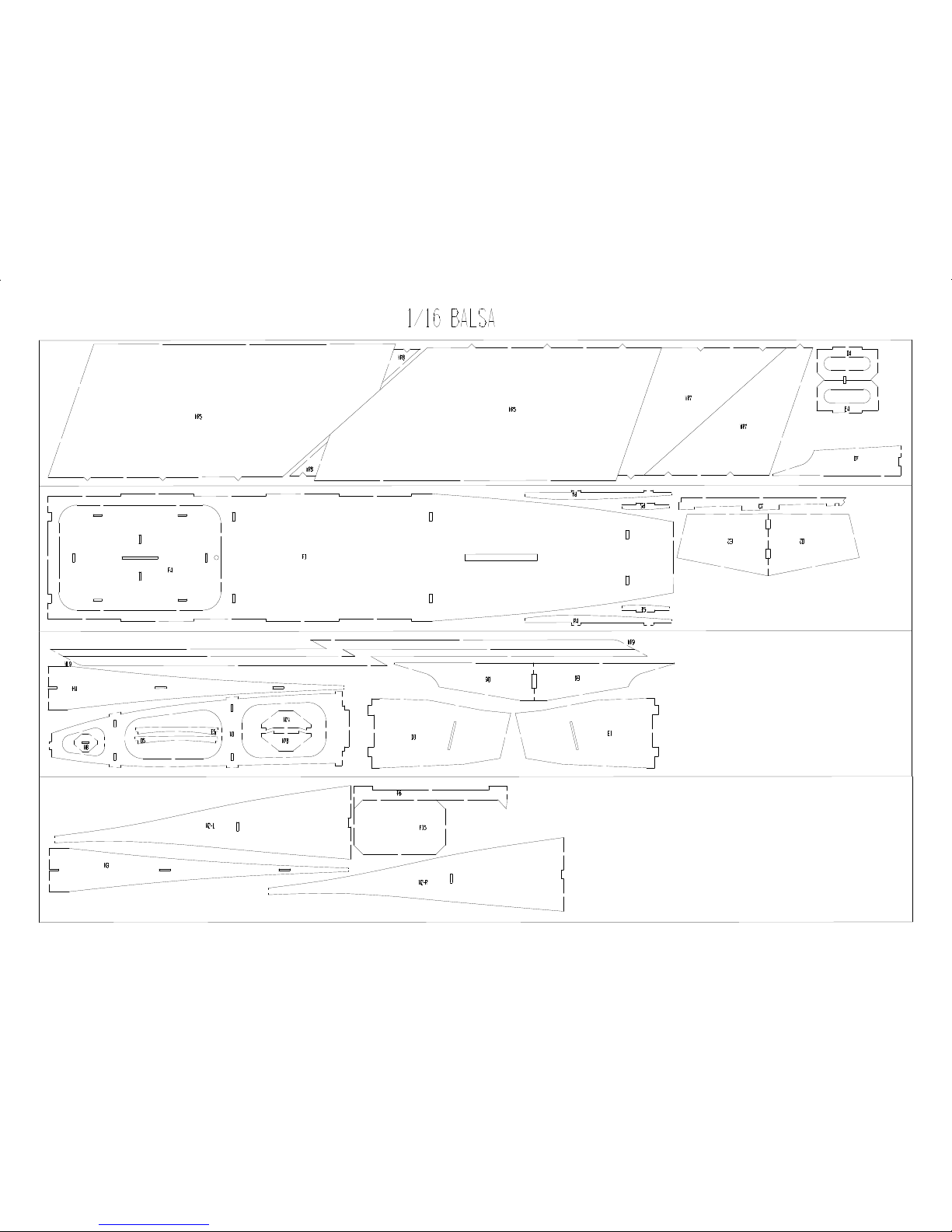
• Eight sheets of laser cut 1/16” balsa
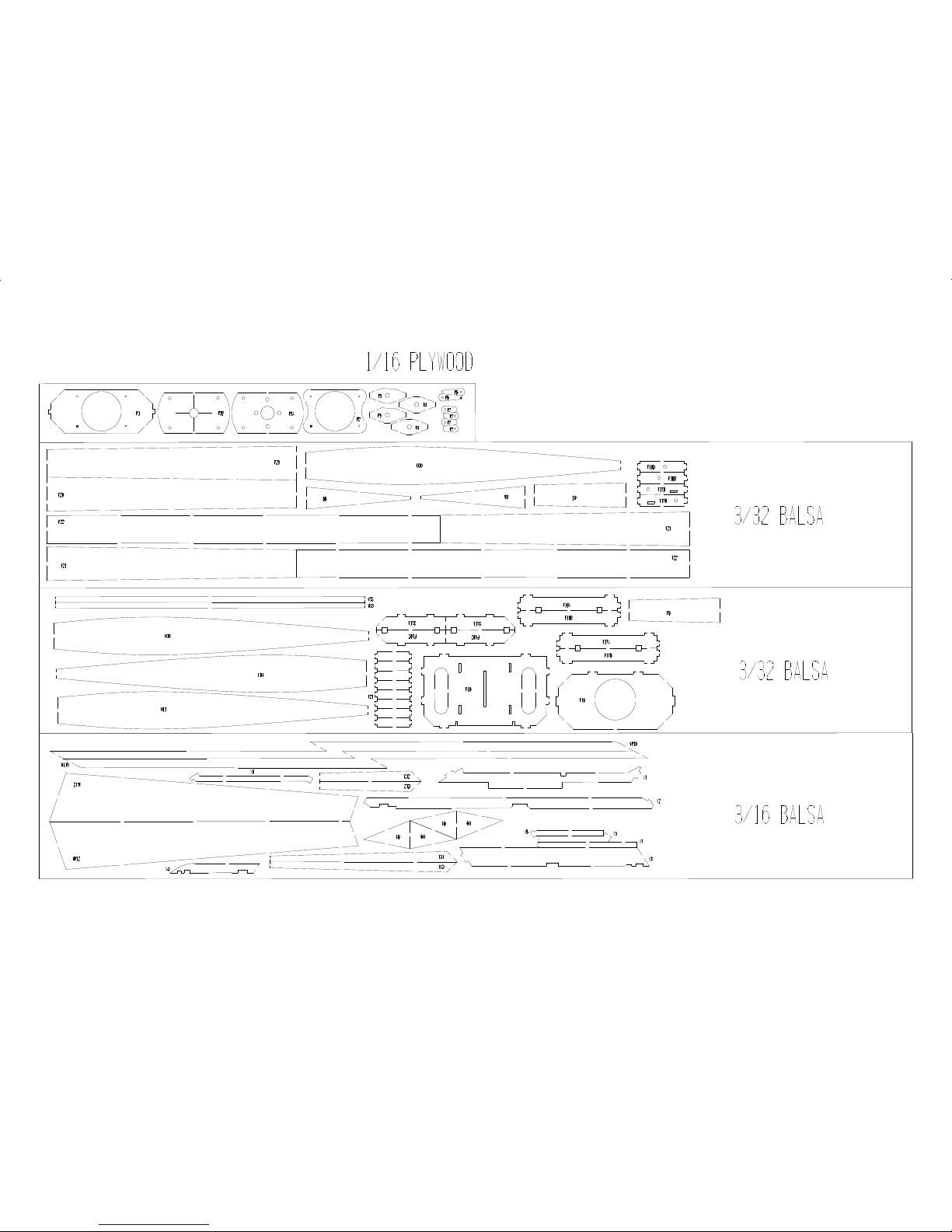
• Two sheets of laser cut 3/32” balsa
• One sheet of laser cut 3/16” balsa
• One sheet of laser cut 1/16” plywood
©McKELLAR AERO DESIGN
2
Ver. 1.2
Page 3
Required to Complete
• Two lengths of 1/8” diameter carbon fibre rod (7-11/16” and 11-9/16” long)
• One package of CA hinges
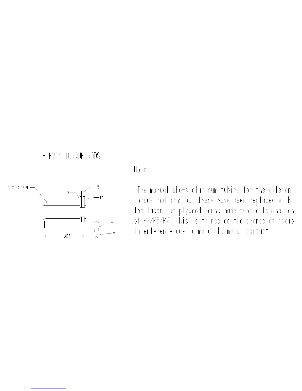
• Two pre-bent pieces of 1/16” piano wire for the aileron torque rods
• Two 12” lengths of 0.032” piano wire
• Two plastic tubes
• Two 1/8” diameter by 1/8” long rare-earth magnets
• One length of 3/32” aluminum tube
• Four 2-56 X ¼” socket head cap screws
• Two Dubro Micro E/Z Connectors
• Covering
• Self-adhesive Velcro (can be found at most hardware stores)
• Medium and thin cyanoacralate (CA)
• 10 minute epoxy
• Two micro servos weighing 8-10g with 12-15 oz-in torque rating
• One micro receiver
• One speed control with BEC (battery elimination circuit) suitable for your motor.
General Building Instructions
• It is best to remove the parts from the laser cut sheets only as they are needed. This
will reduce any chance of confusion since some of the smaller parts are not labelled on
the actual part.
• Sand down any remainders of the tabs which held the parts in the sheet.
• Do not force any tabs into the slots. Enlarge the slots if the tabs are a bit tight. A
jewellers file or nail file works well for this.
• Be sure to check the fit of each part and assembly before applying glue.
• Use medium CA for all joints unless told otherwise.
Building the Fin
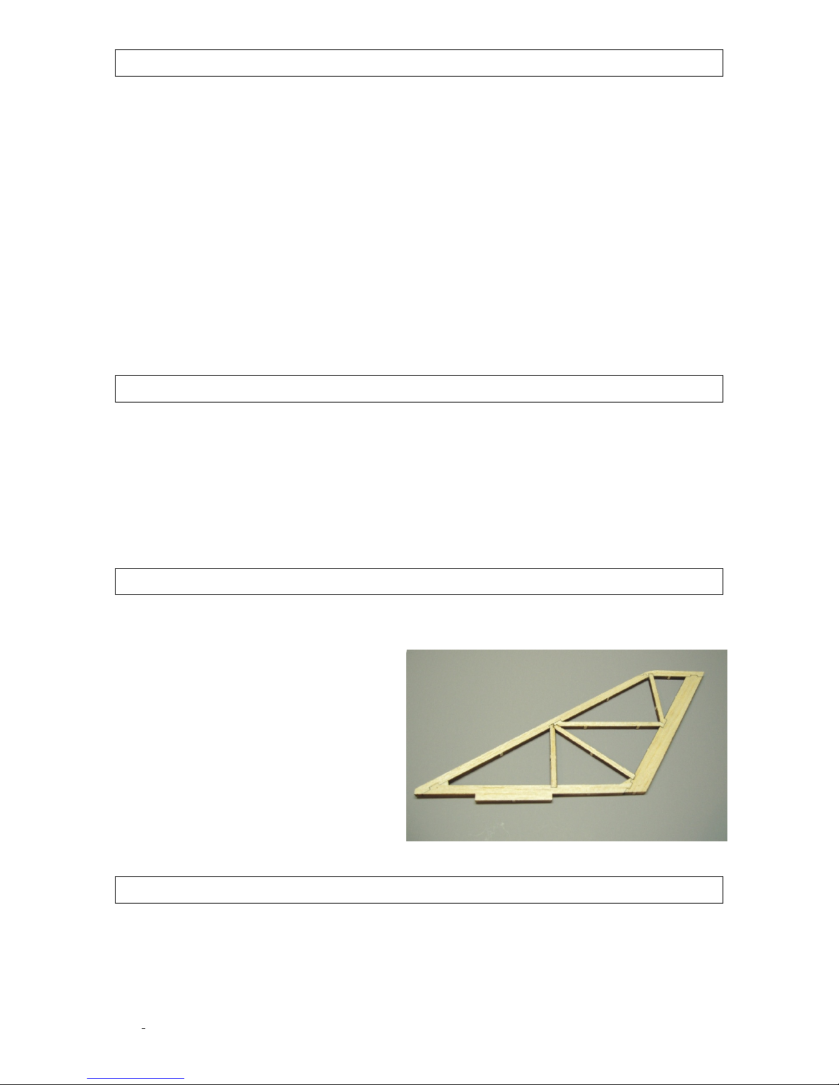
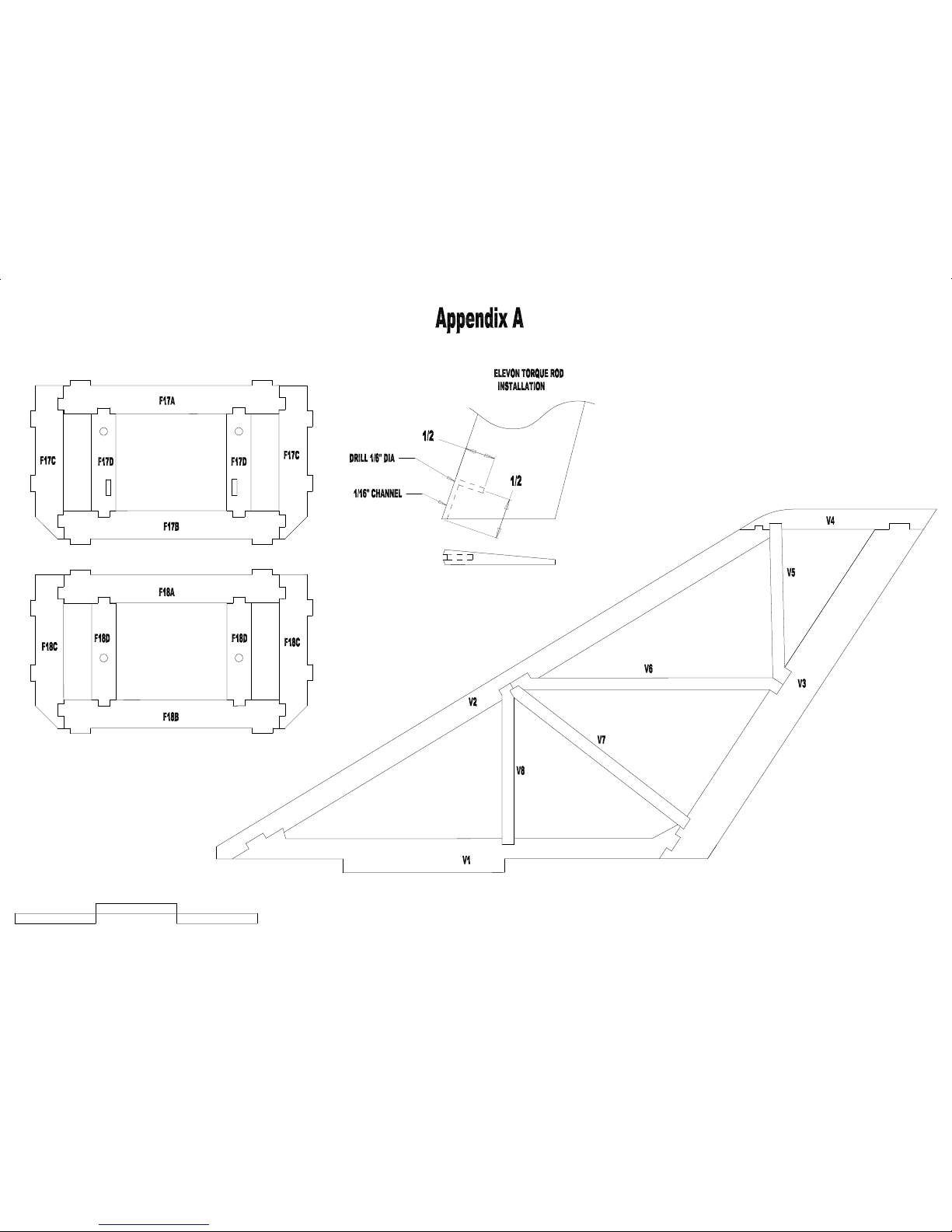
Begin by removing Appendix A from the manual and place on building board with wax paper
over the sheet to protect the plan. Pin V1 in place over the plan. Glue V2 to V3 and then pin V4
in place. When everything is aligned, you
can glue V4 to both V2 and V3. Now fit the
remaining parts (V5, V6, V7 and V8) in
position and apply med. CA to the joints.
Once all the glue has cured, you can remove
the fin from the building board. Lightly sand
both sides so they are flat with no lumps.
The leading edge and tip should be rounded
over with a sanding block. Finally, the
trailing edge can be sanded to a taper with
a thickness of roughly 1/16” at the outer
edge. Make sure this taper is even on both
sides of the fin.
Building the Wing
The first step is to lay the lower wing skins in place on a flat surface and glue them together. The
right wing lower skins are made from parts WR1, WR2, WR3, and WR4. The left wing lower
©McKELLAR AERO DESIGN
3
Ver. 1.2
Page 4
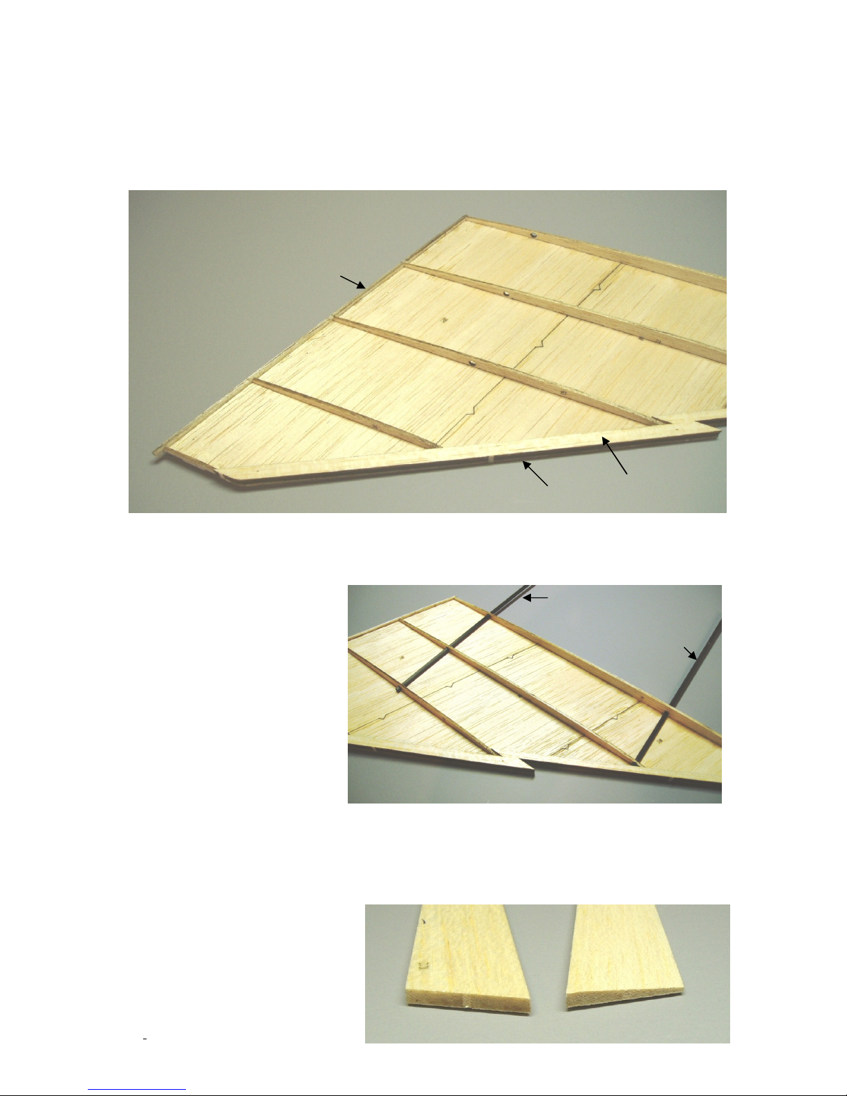
skins are made from WL1, WL2, WL3 and WL4. Make sure these parts are lying flat when you
R1
R2
R3
R4
R5
W13
WR9
WR10
LONG ROD
SHORT ROD
glue them together. Once the glue has dried, give all the joints a light sanding so they are flush.
Next, the wing ribs R1-R5 are fit in place on the lower wing skin. The tabs in the ribs fit into the
slots in the skin. Once the ribs are in place and everything is flat you can glue the wing ribs to
the skin with medium CA. Once the glue has cured, sand the ends of the ribs so they are flush
and perpendicular to the edges of the wing skin.
The leading edge is made by laminating WR9 (WR9 on the bottom) and WR10 together for
the right wing. Do the same with WL9 and WL10 for the right wing. Now glue the trailing edge
(W13) and the leading edge in place. Sand the top surface of the trailing edge so it follows the
profile of the wing ribs.
Now, take the short length of
carbon fibre rod and fit it in the
forward holes through R1 and
R2. The rod should protrude
outward of R2 by 1/16”. Apply CA
to the rod/rib joint to fix in place.
Do the same thing with the longer
rod and it should again protrude
1/16” outboard of R3. *NOTE*
only glue the rods into one wing
panel at this time.
The final step is to glue the top
wing skins together like was done
for the bottoms skins. The upper
skin for the right wing is made from WR5, WR6, WR7 and WR8. Similarly, the left skin is made
from WL5, WL6, WL7 and WL8. When these are complete, you can glue the skins onto the
wing panels. Make sure everything fits well before you start with the glue. First, glue the skin to
the leading edge with CA. Apply aliphatic glue on the tops of the ribs and trailing edge. Apply
weight (phone book works well) to the panel and leave this a few hours until it has dried. Now
you can sand off any overhang and
shape the leading edge.
The elevons need to be sanded to
shape. Take the left (WL15) and
right (WR15) elevons and sand a
©McKELLAR AERO DESIGN
4
Ver. 1.2
Page 5
taper so the top surface thins to 1/16” thick at the trailing edge. Mark the leading edge 1/2” in
N1
N5
N6A
N7A
N7B
N6B
N8
N3
N2-R
N2-L
Nose sanded to shape
from the inner end of the elevon and drill a 1/16” diameter hole 3/8” deep. Make a 1/16” slot
from this hole to the inner end. This hole and slot will fit the torque rod. Mark the three hinge
locations on both the wing trailing edge and the elevon leading edge.
Using a hobby knife, make a slot at these locations. Finally, sand the leading edge of the elevons
so a slight bevel (20°) top and bottom. See Appendix B
Building the Nose and Intake Nacelles
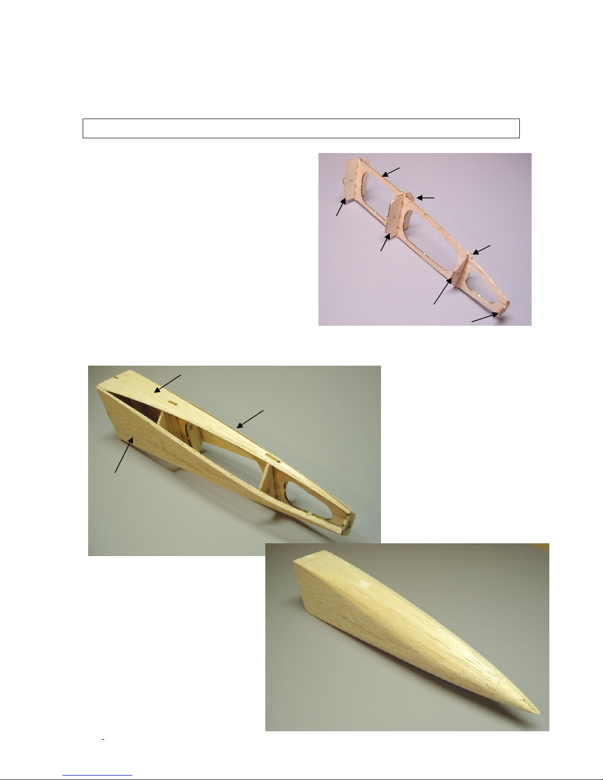
We will build the nose section first. Begin by
gluing the formers N5, N6A, N6B, N7A, N7B
and N8 in place on N1. Make sure these parts are
perpendicular to N1. Next, fit the top sheeting
(N3) and the bottom sheeting (N4) in place and
apply CA to the joints. The right (N2-R) and left
(N2-L) side sheeting can now be glued in place.
Sand the sheeting edges so they are flush with the
former corners. Now you can glue the corner
sheeting in place. Glue one top corner sheet
(N10) and one opposite bottom corner sheeting
(N11) in place. Trim these parts flush with the top
and side sheeting and then apply the remaining
top and bottom corner sheets (N10 and N11).
Sand the sheeting edges flush with one another
and sand the sheeting flush with the front N8 and N5. Laminate the nose block from the four
parts labelled N9 and glue in place on N5. Finally, sand the sheeting and nose cone into a nice
round shape.
©McKELLAR AERO DESIGN
5
Ver. 1.2
Page 6
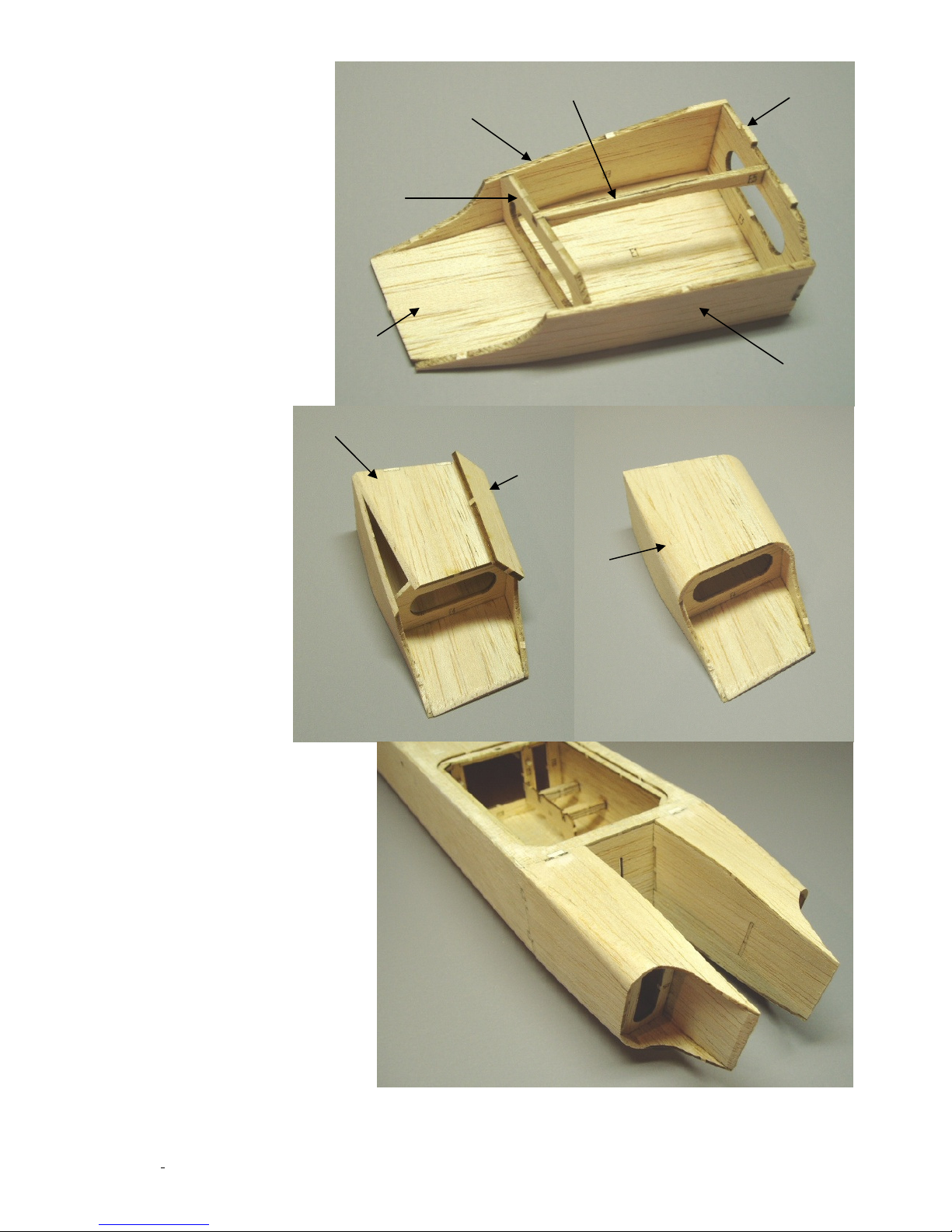
The intake nacelles are
E1
E6
E3
E7
E4
E5
E2
E9
E8
Nacelle sanded to shape
built next. Start by
building the left nacelle.
Glue E3 and E4 onto E1
making sure they are both
perpendicular to E1. Fit
E5 in place and apply
glue. Now, glue the top
sheet (E6) and the
bottom sheet (E7) in
place. The outer side
sheet (E2) is glued on
next. Sand the sheeting
edges so they are flush
with the corners of E3
and E4. Glue E8 onto the
top corner and E9 on the
lower corner. Carve and
sand the corner
sheeting to a round
profile.
The right nacelle is
built in the same
way using parts
labelled D1 to D9.
Once the intake
nacelles are finished
it is time to mount
them on the
fuselage. Glue the
intake nacelles into
F16 on the forward
end of the fuselage.
The tabs will fit
right in place. Blend
the nacelles into the
fuselage with some light
sanding.
Nacelles glued onto
the fuselage
©McKELLAR AERO DESIGN
6
Ver. 1.2
Page 7
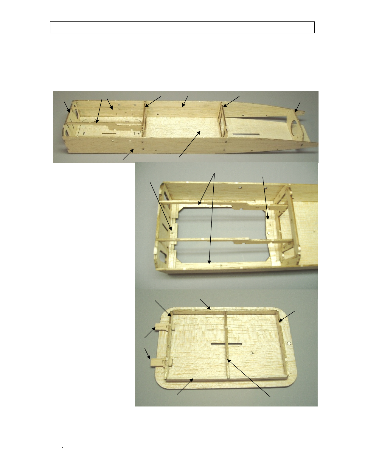
Building the Fuselage
F16
F17 F18
F19
F14
F3R
F3L
F1
F8
F6
F7
F11
F9
F13
F9 F12
F10
The first step is to build the two center fuselage formers (F17 and F18). These are built up
from parts F17A,B,C,D and F18A,B,C,D. Assemble these parts over Appendix A and apply CA to
all the joints. Lay F1 flat on the building board and fit the formers (F16, F17, F18 and F19) in
place. Use a small square to keep the formers square to F1 and glue the formers to F1 with some
CA. The fuselage sides (F3R and F3L) are now fit in place. Make sure all the joints are tight and
then apply CA to the joints. Glue the two F14’s in place. Using a sharp hobby knife, cut the
battery hatch (F4) free of F1 and set aside.
The battery opening
doublers will now be
installed. Now, glue F8 in
position up against the
forward former (F16). Next,
the two F6 doublers are
glued in place. Make sure
these parts are pressed
against F8 and the fuselage
sides. Finally, F7 is glued in
place. Take one of the
magnets and glue it in the
hole in F7. The magnet
must be flush with the top
side of F7.
Take the part F4 that you
cut from F1 and glue in
place the two F9’s, F11,
F12 and F13. Then fit the
two F10’s in position and
apply glue to the joints. Glue
a 1/8” magnet in the hole in
F4 making sure it is flush
with the underside of F4.
Make sure that the battery
poles in the fuselage and
battery hatch are opposite
so that the hatch will close.
This completes the battery
hatch for now.
Remove the eight F21
parts from the sheet and
laminate then together is
pairs. Fit these in the slots in
the fuselage sides and the two F14 parts. Apply CA to the joints to fix in place. Using the carbon
fibre spars or a 1/8” dowel, position P4 so the hole lines up with the forward spar hole in both
©McKELLAR AERO DESIGN
7
Ver. 1.2
Page 8
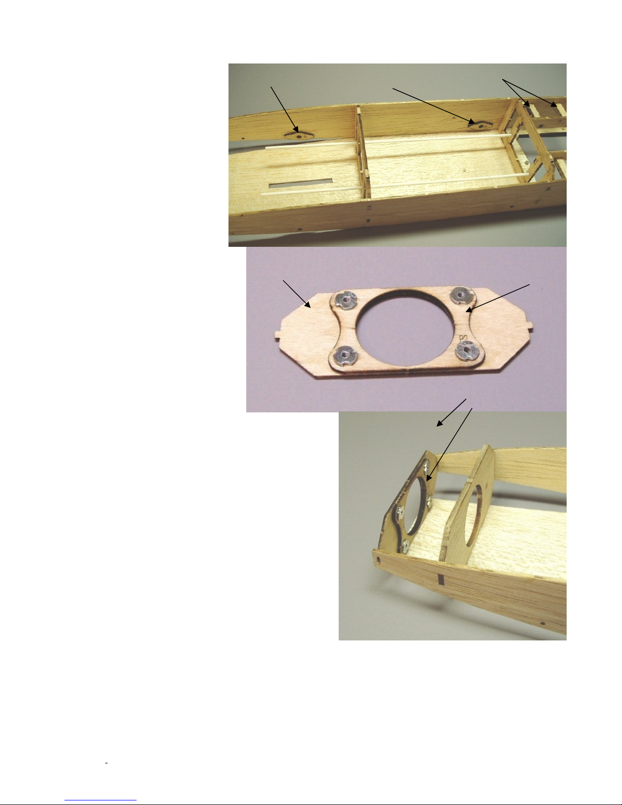
fuselage sides. Carefully apply CA to P4 making sure the dowel or spar does not get glued in
F21 laminations
P5 P4
P1
P2
Epoxy fillet here
place. Do the same thing with P5 and the rear spar hole on both fuselage sides.
Take the two plastic tubes
and cut them so you have
two lengths 8.5” long. Fit
these tubes in place through
the holes in the F17 and
F18 formers. The forward
ends of the tubes should
protrude beyond F17 by
1/4”. When these tubes are
positioned properly, glue in
place with CA.
The firewall is made by
laminating P1 and P2
together. Make sure the
small holes in P1 and P2
line up before gluing. Use
10 minute epoxy to glue these
two parts together. Note that
the photo shows blind nuts
which were used on the
prototype but not required for
the kit.
Make sure the firewall is
perpendicular to the fuselage
top (F1) and glue the firewall to
the fuselage sides. Next, bend
F1 into contact with the firewall
and apply glue to the joint.
Make sure the firewall has not
shifted during this process.
©McKELLAR AERO DESIGN
8
Ver. 1.2
Page 9
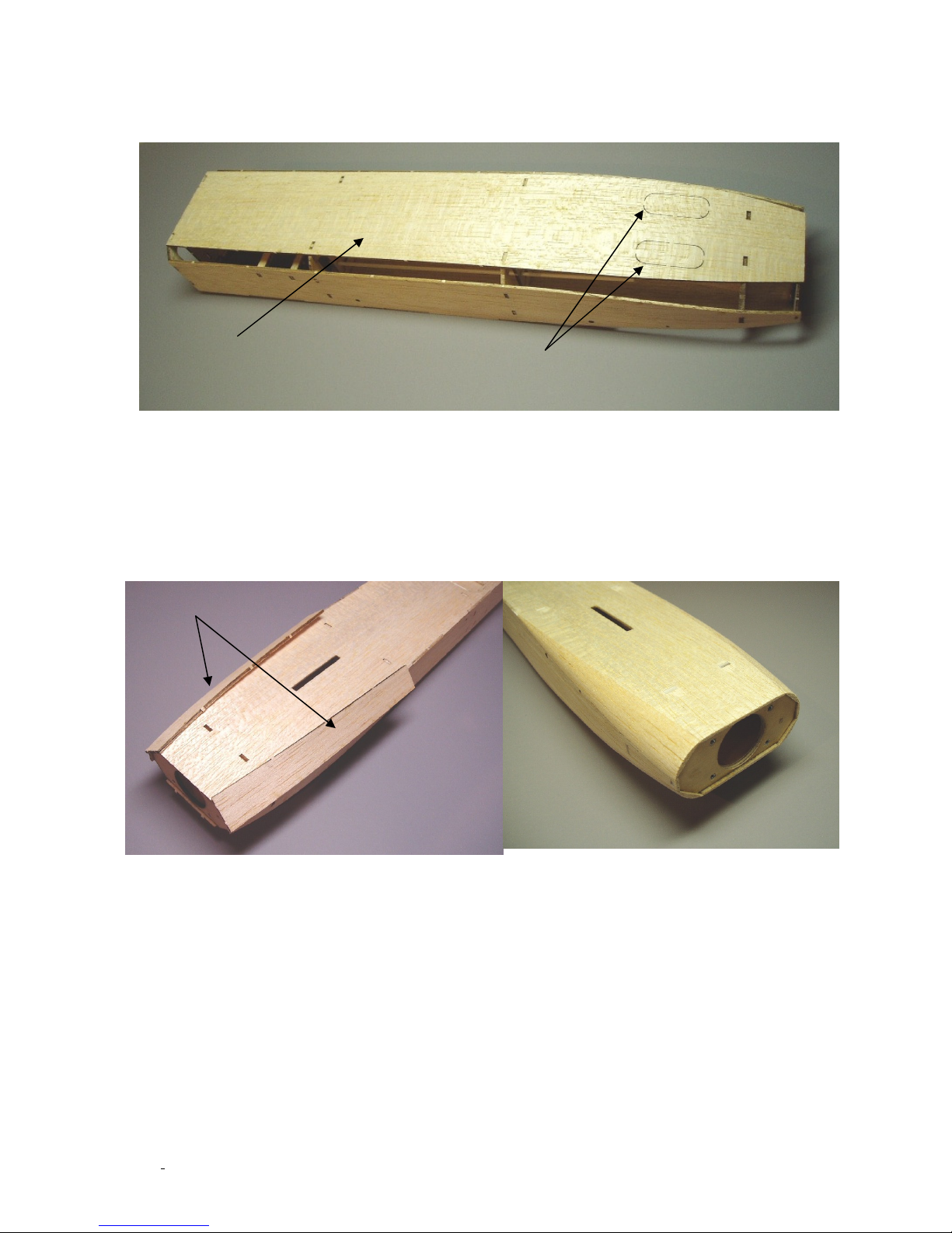
F2
Cooling holes
F22
The fuselage bottom skin (F2) can now be glued in place. After the bottom skin is in place,
apply a fillet of epoxy with some filler on the firewall/fuselage skin joints. This will strengthen the
joint and secure the firewall very well.
The corner sheeting will now be installed. Start with the top side. Sand the edges of the fuselage
sides and top sheeting on an angle so they match the angled edge of the former F19 and the
firewall. Take F20 sheeting and glue it over this corner. Do this on both sides of the fuselage and
then sand a radius into this edge.
Do the same procedure for the bottom corners of the fuselage using F22 for the long section
and F23 for shorter aft section. Cut out the two cooling holes in the lower aft fuselage skin after
all the sanding is complete. This finishes up the fuselage for now.
©McKELLAR AERO DESIGN
9
Fuselage sanded to
shape
Ver. 1.2
Page 10
C2
C3
C5
C1
C4
C7
C6
C9
C8
C12
C11
AFT Spine
FWD Spine
Canopy
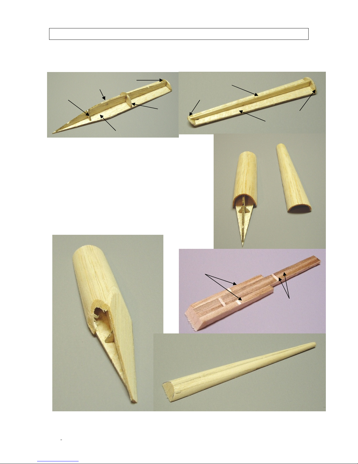
Building the Canopy and Spine
Start by gluing the canopy formers (C3, C4 and C5) onto C2. Now glue the canopy base (C1)
onto the bottom of C2 and the formers. Frame up the fwd spine by gluing the formers C8 and
C9 onto C7 and then gluing C6 to this assembly.
Cut some balsa from sheet MAD-ARW12 and sheet both
the fwd spine and the rounded section of the canopy.
Bending the sheeting into shape is easier if you wet the
outside with some window cleaner containing ammonia.
Once this sheeting has dried fully, trim and sand the edges
as well as the forward section of the canopy sheeting so
that you can apply flat sheeting to the forward area. Sheet
one side of the fwd canopy and then sand the sheeting
edge flush with the opposite face. Apply sheeting to the
remaining face and sand everything flush.
The rear spine is laminated from the two C11 and C12
parts. Now, trim and sand this part so it blends in with the
rear end of the fwd spine and the fin.
©McKELLAR AERO DESIGN
10
AFT Spine sanded to
shape
Ver. 1.2
Page 11
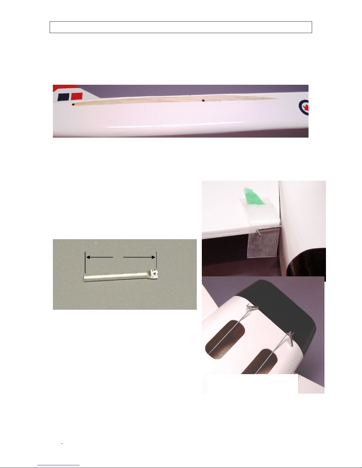
Final assembly
1”
Covering removed to glue wing in place
Cover all the individual parts with your favourite film. Remove any covering from where the parts
will be glued together. Glue the wing panel with the carbon fibre spars in place first. Now glue
the second wing panel in place using a little epoxy on the carbon spars and CA on the wing rib.
The nose is glued on with some CA. Glue the fwd spine in place on the battery hatch and fit the
hatch in position once the glue has set. Glue the canopy on making sure it lines up with the fwd
spine. Next, the fin is glued in place using epoxy in the fuselage slot and CA on the fin base.
Finally, glue the aft spine in place again making sure it lines up with the fin and fwd spine.
Remove six hinges from the hinge sheet and mount them in the elevons. Press the hinges
halfway into the elevon slot and apply some thin CA to the joint. Let this CA cure fully before
going on to the next step. Sand the ends of the elevon torque rods with some 220 grit sandpaper
and then clean these ends with alcohol or acetone. Fit the elevon torque rods through the pre-cut
holes just aft of the wing trailing edge. Make sure these are installed correctly. The end inside
the fuselage should be pointing down towards the
belly of the plane. Tape a small piece of wax paper
onto the inner trailing edge of the wing. Apply some
epoxy to the torque rod hole and slot in the elevons
and fit in place on the wing. When the elevon is
positioned properly, apply some thin CA to the hinges
so that they are locked into the wing trailing edge. Set
aside until the epoxy has cured fully.
Take the aluminum tube and cut two 1” lengths from
it. Now, and flatten one end of each tube with smooth
jawed pliers. Drill a 1/32” hole in this flattened area
making sure that the holes in both tubes are the same
distance from the other end of the tube. If this
distance is unequal, you will have uneven control
throws on the elevons. Make a “Z” bend on one end of
both 1/32” steel rods and fit the aluminum tubes on
theses “Z” bends. Apply some epoxy to the end of the
torque rod and inside the aluminum tube. Using the
motor hole, slip the pushrods through the plastic tubes
and slip the aluminum tube onto the end of the elevon
torque rod. Leave the fuselage upside down while this epoxy cures.
Bolt your motor to P3A or P3B and then attach that onto P1 using the supplied #2 screws .Note
that P3b has no bolt holes for the motor so you can drill your own mounting holes should your
selected motor not fit P3A.
©McKELLAR AERO DESIGN
11
NOTE: Aluminum tubes shorter
than required in this photo
Ver. 1.2
Page 12
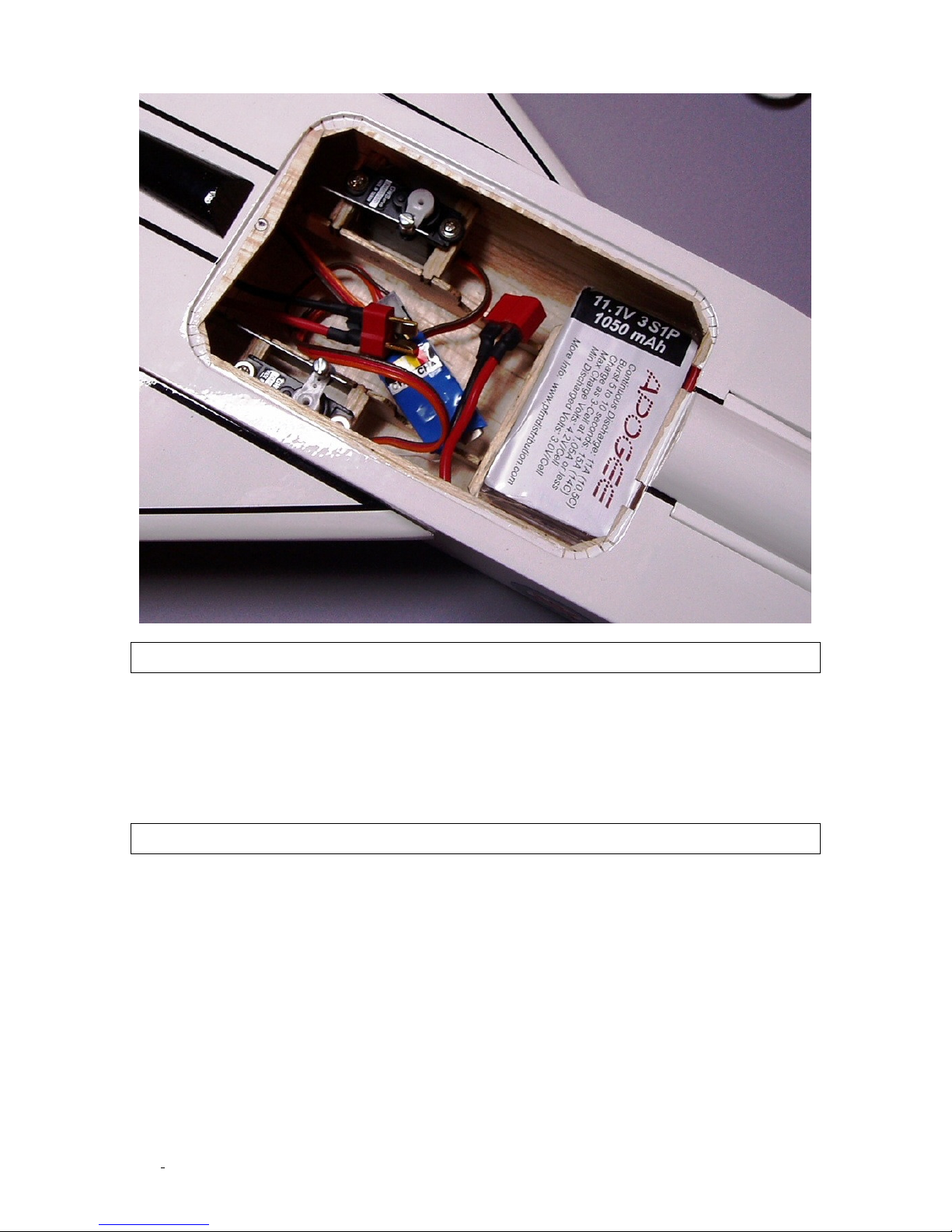
Finally, install the servos and receiver and apply some sticky Velcro onto the battery tray F15
and glue it in place on the forward end of the F14 stiffeners.
Prepare for flight
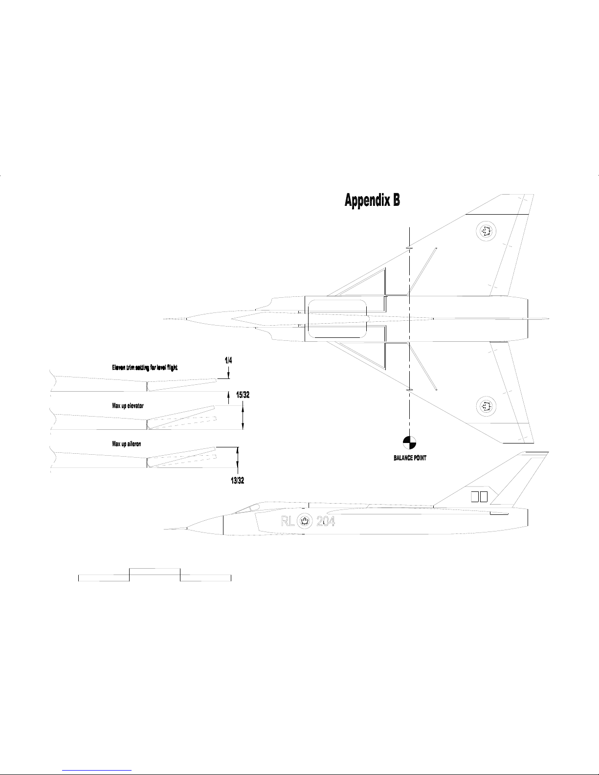
Support the wing at the location shown in Appendix B and place the receiver, speed control and
battery in position so that the plane balances level. You should be able to achieve this balance
point by shifting the battery fore and aft. Do not fly the plane with the balance point further aft
than the indicated range. A tail heavy plane is unstable and extremely difficult to fly.
Set the control throws as shown in Appendix B. Use the bottom side of the wing root as the
reference plane.
First flight
Be sure to do a range check before the first flight to make sure the radio is operating properly.
Check once again that the control surfaces are moving in the correct direction when the
transmitter sticks are moved. Apply three to four clicks of up elevator (nose up) for the first
launch. Get a friend launch the plane for the first flight. Apply full power and have your friend
launch the plane into the wind at a level altitude. Get a feel for the plane and try a few
approaches to get ready for the landing. You will find that the plane lands at a nose high attitude
and fairly slow speed. I hope you will have many enjoyable flights with this new plane!
Good flying!
©McKELLAR AERO DESIGN
12
Ver. 1.2
Page 13
Page 14
Page 15
Page 16
Page 17
Page 18
Page 19
 Loading...