

MCK PBXgateway Installation Manual

PBX
gateway
Quick Installation Guide
Purpose of this Document
This document provides the step-by-step process
for the complete installation, basic configuration,
and troubleshooting of the PBXgateway.
Table of Contents
PURPOSE OF THIS DOCUMENT ............... 1
SAFETY CONSIDERATIONS....................... 1
TABLE OF CONTENTS................................. 1
Safety Considerations
SUPPORT TELEPHONE NUMBER............. 2
SPECIFICATIONS.......................................... 3
!
IMPORTANT SAFETY INSTRUCTIONS
!
Do not install this product near water.
Example: In a wet basement location.
!
Do not overload wall outlets, as this can
result in the risk of fire or electrical shock.
PREREQUISITES FOR INSTALLATION .. 4
PARTS PROVIDED ........................................ 5
PARTS NOT PROVIDED............................... 6
TYPICAL INSTALLATION .......................... 6
POWER-UP...................................................... 9
BASIC CONFIGURATION.......................... 10
Issue 2.1/December 1999
!
Do not attach the power supply cord to
building surfaces. Do not allow anything to
rest on the power cord. Do not locate this
product where persons walking on it will
abuse the cord.
!
Do not operate the system if chemical gas
leakage is suspected in the area. Use
telephones located in some other safe area to
report the trouble.
PBXgateway QIG Page 1 G-6000G-SMM
TYPES OF NETWORKS.............................. 15
YNCHRONOUS-SERIAL DEVICE
S
EVICE
IP D
OPTIONAL CONFIGURATION................. 18
..................................................... 17
................... 16

Support Telephone Number
Call the MCK Communications Helpline (1-888-454-5828) or your MCK Communications authorized
dealer if you need assistance when installing, programming, or using your system. Ask for Customer
Service. Outside the United States or Canada, contact your local MCK Communication representative.
PBXgateway QIG Page 2 G-6000G-SMM

Specifications
Regulatory Approvals
FCC Parts 15 & 68, Subpart B Class B
CE Mark EN50081-1, EN50082-1,
EN60950
NRTL/C CSA Standard C22.2
No.0-M91 , 225-M90
Industry
Canada
System Architecture
CPU Motorola 68MH360, 33MHz
DSP
8 Port
12 Port
Memory
DRAM 4MB
Flash
Memory
Boot
ROM
WAN Design
Protocol Synchronous-Serial
CS-03
Five Analog Devices 2187 52
MIPS
Eight Analog Devices 2187 52
MIPS
4MB
512KB
Interfaces
Ethernet Single 10BaseT
Serial EIA/TIA-232, EIA/TIA-
530
Management
Console
PBX/KSU 12 digital line interfaces,
Voice
Voice
compression
Protocols and
Services
WAN Remote Voice Protocol
LAN
Electrical
Line Voltage 100-240v, switchable
Frequency 50-60 Hz
Max Power
Consumption
Power Input
Filter
Serial RS-232, DB9
RJ-21
G.729a, ADPCM 32,
ADPCM 24
(RVP) (proprietary) over
HDLC
RVP over Internet
Protocol (IP)
0.8 Amps
IEC (with 2A Fuse)
Interface RS-232, V.35 or RS-530
Encapsul
ation
PBXgateway QIG Page 3 G-6000G-SMM
High level Data Link
Control (HDLC)
Mechanical
Dimensions 17” x 8” x 1 ¾” (432mm
x 203mm x 44mm)
Weight 6lbs 7 oz (3 kg)
Environmental
Temperature
Relative
Humidity
32° - 130°F (0° - 55°C)
5 to 95%

Prerequisites for Installation
The following items are required before installing the PBXgateway.
!
Proper wiring with adequate punch down blocks (wired according to Table 3, page 8).
!
A 50 pin cable with an RJ-21 female connector.
!
Appropriate network terminating device must be installed and functioning at both the corporate facility
and the branch office.
!
The data connection between the corporate facility and the branch office MUST be operational and
configured properly.
!
The network termination equipment must support: an RS-232, V.35 or V.530 synchronous interface or
support IP devices over Ethernet.
!
The system has been designed to operate from 100-240 VAC, 50-60Hz. Power should not be applied
to the Gateway unit until specified in the installation procedures.
!
The Gateway’s power supply and cabling should be installed away from high power/high RF noise
devices such as computers, fans, fluorescent ballast, power supplies, etc.
!
Use good wiring practices. Do not run wires over fluorescent lights, computers, air conditioners, etc. as
this can introduce noise to the modems.
!
The distance from the PBX to the PBXgateway should not exceed 500 feet.
PBXgateway QIG Page 4 G-6000G-SMM
Parts provided with the PBX
Qty Description Provided
1
1Power Cord Yes
1 RS-530 cable Yes
gateway
PBXgateway
Yes/No
Yes
1 50 pin, RJ-21 cable w/male
connectors
- Mounting Hardware Yes
2 Mounting Brackets (2) Yes
1 System Administrator’s Guide Yes
1 Quick Installation Guide Yes
1 Application Guide Yes
Table 1. Parts provided with the PBXgateway
Note: The RJ-21 cable is not provided with the Gateway unit but can be ordered through MCK.
No
See note
PBXgateway QIG Page 5 G-6000G-SMM
Parts not provided with the PBX
!
Digital telephones and communication line cords are NOT supplied with this system.
gateway
Note: Use two-wire digital display phones only.
!
Cat 5 Ethernet cable for 10baseT networks.
!
Punch down blocks necessary to interface between the RJ-21 connector and the PBX.
!
50 pin cable with RJ-21 connectors to interface between the punch down block and the
PBXgateway. (see Table 3, page 8)
!
DB-9 serial RS-232 cable for the management console.
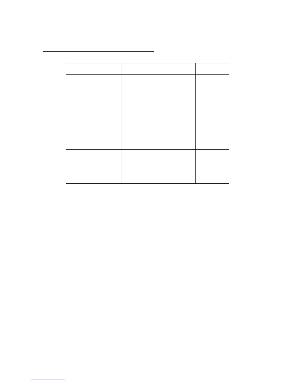
Typical Installation
A typical installation of the PBXgateway is shown in Figure 2
RJ-21
(up to 24 Ports)
Punch Blocks
RJ-21
(up to 12 Ports)
Cross-Connect
Wires
PBX
Figure 2.
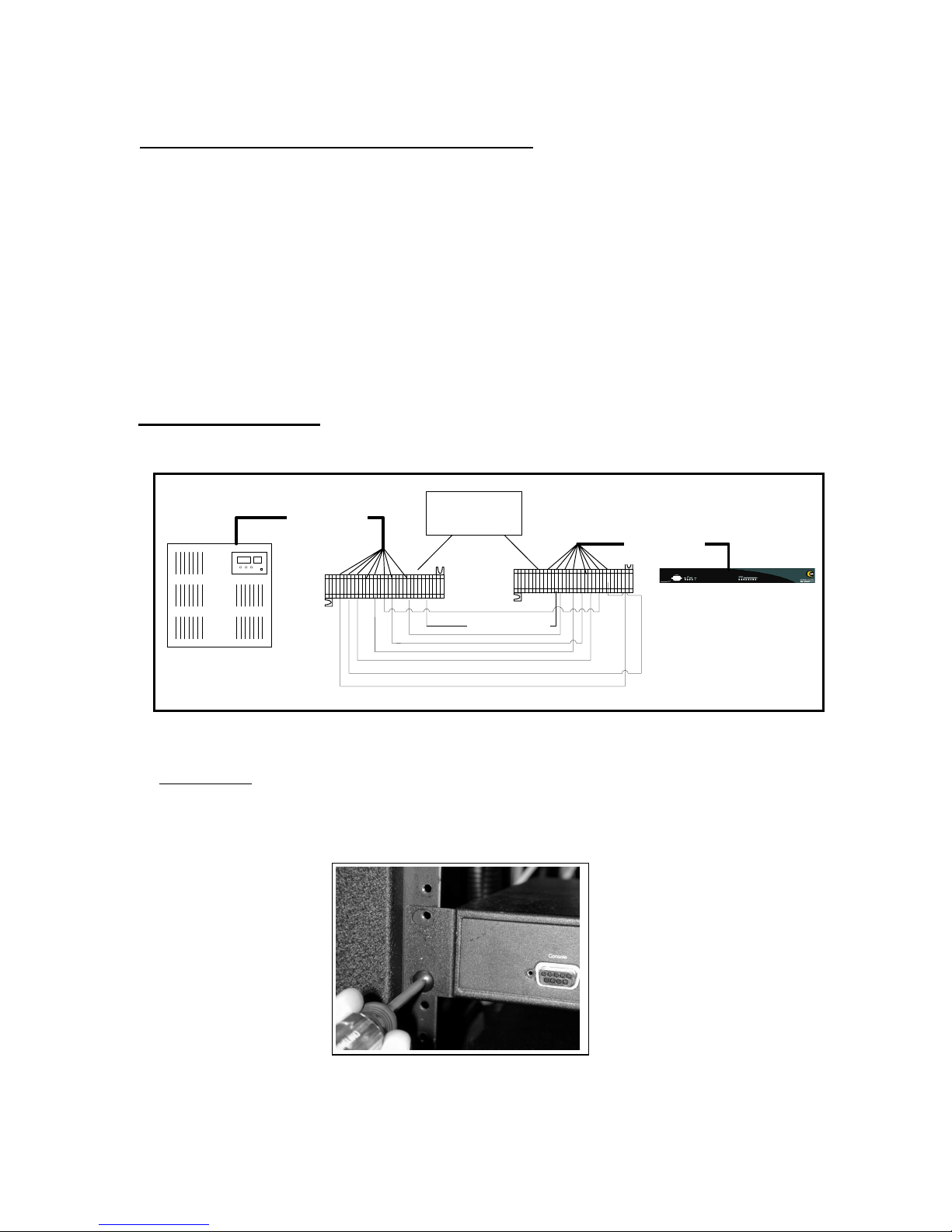
Mounting
The PBXgateway can be mounted in a standard 19-inch communication rack using
provided hardware (Figure 3) or simply placed on a shelf within the rack.
PBXgateway
PBXgateway QIG Page 6 G-6000G-SMM
Figure 3.
 Loading...