

MCK EXTender PBXgateway, PBXgateway Installation Manual

TM
Quality is our job. Customer satisfaction is our mission!
PBXgateway
Quick Installation Guide
G-6000G-SXM Rev AJ
May 08, 2005

Copyright
© Copyright 2005 Citel Technologies All rights reserved.
No part of this publication, including text, examples, diagrams, or icons, may be reproduced, transmitted,
or translated in any form or by any means, electronic, mechanical, manual, optical or otherwise, for any
purpose, without prior written permission of Citel Technologies.
Information in this publication is subject to change without notice. Citel Technologies may have patents or
pending patents applications, trademarks, copyrights, or other intellectual property rights covering subject
matter in this publication. The furnishing of this document does not give you license to these patents,
trademarks, copyrights, or other intellectual property.
Trademarks
© 2004 Citel Technologies All rights reserved.
MCK, the MCK logo, PBXgateway I, PBXgateway II, MCK EXTender 1000, MCK EXTender 3000, MCK
EXTender 4000, MCK EXTender 6000 and MCK EXTender 7000 are trademarks or registere d
trademarks of Citel Technologies or its wholly-owned subsidiaries in the United States and other
jurisdictions. All other trademarks, registered trademarks and service marks are the property of their
respective owners.
PBXgateway Quick Installation Guide 2

Table of Contents
Table of Contents........................................................................................................................................3
Purpose of this Document .........................................................................................................................5
Naming Conventions.................................................................................................................................5
Safety Considerations ...............................................................................................................................5
Support Telephone Number......................................................................................................................6
Prerequisites for Installation......................................................................................................................6
Network Requirements..............................................................................................................................6
ISDN Requirements (for Asynchronous connections)...............................................................................7
Information for the System Administrator..................................................................................................7
Installation Components............................................................................................................................8
Parts not provided with the PBXgateway.................................................................................................8
Typical Installation......................................................................................................................................9
Mounting....................................................................................................................................................9
Connections.............................................................................................................................................10
Telephony Wiring.....................................................................................................................................11
VT-100 Setup .............................................................................................................................................11
Power-Up....................................................................................................................................................12
Basic Configuration .................................................................................................................................13
Basic Configuration .................................................................................................................................14
Installation Environments........................................................................................................................15
Synchronous-Serial Device (RVP_Direct)..............................................................................................16
Prerequisites for Configuration ............................................................................................................16
Asynchronous-Serial (RVP_Direct).........................................................................................................17
Prerequisites for Configuration ............................................................................................................17
IP Device (RVP_IP)...................................................................................................................................18
Prerequisites for Configuration ............................................................................................................18
Dial-Up Management Console .................................................................................................................19
Installing the Modem at the Gateway Site...........................................................................................20
Set Up Wizard............................................................................................................................................21
Optional Access Connections.................................................................................................................22
Remote Access Connection....................................................................................................................22
Modem Connection..............................................................................................................................22
Modem Pinout Information...................................................................................................................22
Modem DIP switch...............................................................................................................................22
Modem Connection Procedure............................................................................................................24
Telnet Connection ...................................................................................................................................24
HTML Interface........................................................................................................................................25
Optional Configuration.............................................................................................................................27
Enabling ConneX.....................................................................................................................................27
Procedure (Meridian/DEFINITY)..........................................................................................................27
Procedure (Norstar).............................................................................................................................29
ConneX Parameters................................................................................................................................30
Configuring the SMTP Server .................................................................................................................31
Norstar KSU ConneX Configuration........................................................................................................32
Trunk Port KSU Configuration – Line Assignment Method .................................................................32
Bridged Appearance– ConneX_Session Port as Ghost Set................................................................32
Terminals and Sets..............................................................................................................................32
Lines.....................................................................................................................................................32
Definity PBX ConneX Configuration.......................................................................................................33
SCENARIO #1: Office Phone Used in Conjunction with the ConneX Phone .........................................33
Provisioning a New Extension for the ConneX Phone ........................................................................33
SCENARIO #2: Only ConneX Phone Is Used.........................................................................................34
Meridian PBX ConneX Configuration......................................................................................................34
SCENARIO #1: Office Phone Used in Conjunction with the ConneX Phone .........................................34
Provisioning the Primary Voice Channel of the Mobile Phone’s TN – Ch1.........................................35
Provisioning the Secondary Data Channel of the Mobile Phone’s TN – Ch2......................................35
PBXgateway Quick Installation Guide 3

SCENARIO #2: Only Mobile Phone Is Used...........................................................................................35
Provisioning the Primary Voice Channel of the Mobile Phone’s TN – Ch1.........................................35
Provisioning the Secondary Data Channel of the Mobile Phone’s TN – Ch2......................................36
Example for Scenario #1 – Programming the Primary Voice Channel (Ch1)......................................37
Example for Scenario #1 – Programming the Secondary Data Channel (Ch2)..................................38
DEFINITY ECS Configuration .................................................................................................................39
Termination of the EXTender 1000 and 3000 .....................................................................................39
Prerequisites for Configuration ............................................................................................................39
Procedure ............................................................................................................................................39
Meridian PBX Configuration....................................................................................................................41
Termination of the EXTender 3000......................................................................................................41
Prerequisites for Configuration ............................................................................................................41
Procedure ............................................................................................................................................41
B1 (Ch 1)..............................................................................................................................................41
User Input ............................................................................................................................................41
B2 (Ch 2)..............................................................................................................................................42
PBXgateway Quick Installation Guide 4

Purpose of this Document
This document provides the step-by-step process for the complete installation, basic configuration, and
troubleshooting of the PBXgateway™.
Naming Conventions
The PBXgateway™ I is also referred to as PBXgateway or Gateway within this document.
Safety Considerations
!
IMPORTANT SAFETY INSTRUCTIONS
• Do not install this product near water.
Example
• Do not overload wall outlets, as this can result in the risk of fire or electrical shock.
• Do not attach the power supply cord to building surfaces. Do not allow anything to rest on the power
cord. Do not locate this product where persons walking on it will abuse the cord.
• Do not operate the system if chemical gas leakage is suspected in the area. Use telephones located
in some other safe area to report the trouble.
: In a wet basement location.
PBXgateway Quick Installation Guide 5

Support Telephone Number
Call the MCK Communication’s Helpline (1-888-454-5828) or your MCK Communication’s authorized
dealer if you need assistance when installing, programming, or using your system. Ask for Customer
Service. Outside the United States or Canada, contact your local MCK Communication representative.
Prerequisites for Installation
The following items are required before installing the PBXgateway.
Network Requirements
• Appropriate network terminating device must be installed, configured, and functioning at both the
corporate facility and the branch office and both must support an RS-232, V.35 or V.530
synchronous, asynchronous or Voice over IP interface.
• A 50 pin cable with an RJ-21 female connector.
• Appropriate network terminating device must be installed and functioning at both the corporate facility
and the branch office.
• The data connection between the corporate facility and the branch office MUST be operational and
configured properly. The system has been designed to operate from 100-240 VAC, 50-60Hz. Power
should not be applied to the Gateway unit until specified in the installation procedures.
• The Gateway’s power supply and cabling should be installed away from high power/high RF noise
devices such as computers, fans, fluorescent ballast, power supplies, etc.
• Use good wiring practices. Do not run wires over fluorescent lights, computers, air conditioners, etc.
as this can introduce noise to the modems.
• The distance from the PBX to the PBXgateway should not exceed 500 feet.
• Obtain the following information from your customer:
MODE: (V.35, RS-232, RS-530)_________________
NUMBER OF DS∅s required ____________
56K or 64K_______________
number of DS∅s X 64 or 56K(above) = _________ SYNC RATE ÷ number of stations = _______
If the result is at least 40 KBPS use ADPCM32 voice compression
If the result is less than 40 KBPS but at least 32 KBPS use ADPCM24 voice compression
If the result is less than 32 KBPS but at least 16 KBPS use G.729A voice compression
If the result is less than 16 KBPS, there is not enough bandwidth.
Note: This is a general guideline for calculating bandwidth requirements. For more information, see your
System Administrator’s guide.
• If using an asynchronous connection, an ISDN Terminal Adapter (TAs) from the list below, must be
installed and operational at BOTH the corporate facility and at the Branch Office location. This list is
complete as of the release date of this document. Please refer to MCK’s website for the most up-todate list of recommended ISDN Terminal Adapters.
PBXgateway Quick Installation Guide 6
• If using a synchronous connection, consult the supported TA list.
TA’s (for Async)
MFG Model(s)
(see note)
Motorola Bitsurfr Pro
Bitsurfr Pro EZ
Adtran ISU 128 (see note)
ISU 2X64
Express 3000
Express 3001
Express NTU
3Com ISDN TA
TA’s (for Sync 128k
bonding)
Motorola Bitsurfr Pro
Adtran ISU 128 (see note)
ISU 2X64
CSU/DSU’s
Paradyne Acculink 3165
7110 SNMP
Adtran TSU LT
General
DeskTop 554A
DataComm
RAD FCD-1L
ADC Kentrox DataSmart Max
72761, 78640
Motorola FT100S
Larscom
56/T1
Orion
Note: In order for the Async-RS 232 Dial feature to work properly for these devices, you need to setup
each device to accept incoming “AT Commands”. Consult the documentation provided with each device
for proper instructions.
• Proper wiring with adequate punch down blocks to connect the Remote unit to the phones. Must be
wired according to Table 3, page 7, and provide RJ-21 female connector.
ISDN Requirements (for Asynchronous connections)
Before you install your units, you will need to ensure that you order an ISDN line at both the local site and
the remote branch office. This ISDN line should be capable of the following:
• The ability to make two “data” calls, on each B Channel of the ISDN line.
• If Long Distance, both “data” calls need to be routed as a “data” call.
Note: Confirm this with your Long Distance provider when you order your ISDN Line.
Information for the System Administrator
Once your ISDN line is installed, you will be provided with two Service Profile Identifiers (SPIDs) and also
two Directory Numbers (DNs). These numbers must be provided to the System Administrator.
Note: Make sure you write down the SPIDs and DNs, and keep this in a safe place for reference when
installing the ISDN Terminal Adapters. If you do not have the SPIDs or DNs, you will not be able to
program the ISDN Terminal Adapters.
PBXgateway Quick Installation Guide 7

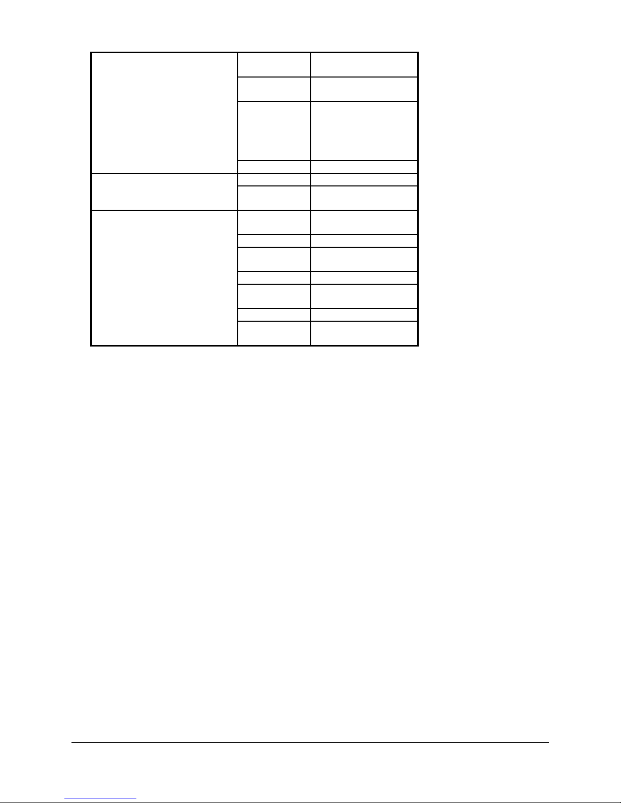
Installation Components
Table 1: Installation Components
Description Function
PBXgateway™
Provided
W/
Gateway
9
Universal Power Cord 120 VAC outlet
DB-9 RS232 Serial Cable (6 foot)
Mounting Hardware To attach brackets for rack mount
Mounting Brackets (2) For rack mounting
RS-530 type cable for high-speed links to
CSU/DSU or terminal adapter
System Administrator’s Guide The complete manual for the
Quick Installation Guide The condensed installation guide
RS-232, DB-25 to DB-9 modem cable
[male-male]. Note: This is a custom made
cable.
50 pin cables with RJ-21 connectors.
Note: RJ21 cables, connecting blocks and
network cables may be ordered through
MCK by calling 1-617-454-6100, and
selecting the Sales option.
Punch down blocks
Console port to PC for system
administration
For connecting WAN ports on
PBXgateway to CSU/DSU or terminal
adapter
PBXgateway.
For connecting the PBXgateway to a
modem for remote configuration.
Telephony interface between the
punch down blocks and the
PBXgateway.
(see page 6)
Provides the interface between the RJ21 connector and the PBX.
9
9
9
9
9
9
9
optional
Needed
but not
supplied
Needed
but not
supplied
Parts not provided with the PBXgateway
Digital telephones and communication line cords are NOT supplied with this sy stem.
Note: Use two-wire digital display phones only.
PBXgateway Quick Installation Guide 8
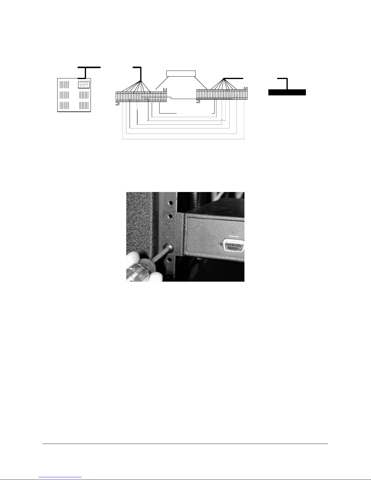
Typical Installation
A typical installation of the PBXgateway is shown in Figure 1.
RJ-21
(up to 12 Ports
per unit)
PBX
Punch Blocks
Cross-Connect
Wires
Figure 1: Typical Installation
Mounting
The PBXgateway can be mounted in a standard 19-inch communication rack using provide d hardware
(Figure 2) or simply placed on a shelf within the rack.
RJ-21
(up to 12 Ports)
PBXgateway
Figure 2: Securing the Unit to a Rack
PBXgateway Quick Installation Guide 9

Connections
The PBXgateway requires connections A through E as shown below.
Table 2: PBXgateway Connections
Letter Label Cable Type Description
A
Console DB-9 Connect to a PC for administration in two ways:
• Direct serial connection to a PC.
• Connect to a modem for remote access. (see
page 14 for modem installation and setup)
Note: Set the COM port as follows; Baud rate:
9600, Databits: 8, Parity: none, Stopbits: 1,
Software flow control: XON/XOFF
B
- Power Connect to a 120VAC outlet. (See page 12)
C
Telephony
Interface
RJ 21 Wire to a punch down block and then to the PBX.
(see Table 3, page 7)
D
WAN1/
WAN2
DB 25, serial,
straight-through
Used for a synchronous or asynchronous-serial
connection. Connect to a TA, CSU/DSU, or other
network device.
Note: An RS-530 type cable or DB-25 to M34
cable should be used for high-speed links to V.35
equipment.
E
LAN RJ 45 Ethernet Used for Telnet management or for conn ecting
the unit to the LAN for use in Voice over IP
(RVP_IP) applications.
PBXgateway Quick Installation Guide 10
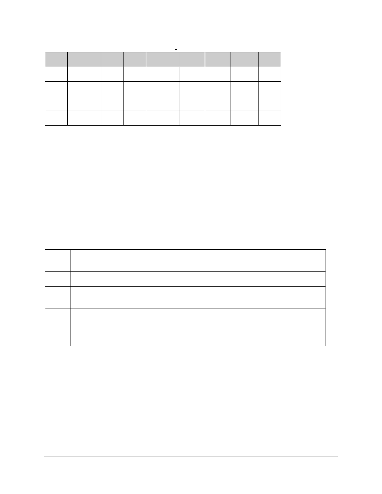
Telephony Wiring
Table 3: Pin Assignments (25-Pair Cable)
Pin Cable
Pair
26
1
28 3 WH/GN
30
5
32
7
Wire Color Abbreviations:
BK=Black, BR=Brown, RD=Red, OR=Orange, YL=Yellow, GN=Green, BL=Blue, VI=Violet, WH=White
SL=Slate
WH/BL
BL/WH
GN/WH
WH/SL
SL/WH
RD/OR
OR/RD
Port Pin Cable
Pair
1
2 36
3 38
4 40
34
9
11
13
15
RD/BR
BR/RD
BK/BL
BL/BK
BK/GN
GN/BK
BK/SL
SL/BK
Port
5 42
6 44
7 46
8 48
Pin Cable
Pair
YL/OR
17
19
21
23
OR/YL
YL/BR
BR/YL
VI/BL
BL/VI
VI/GN
GN/VI
Port
9
10
11
12
VT-100 Setup
Procedure
1. Make sure the PBXgateway is connected as shown on page 9.
2. You will need to use a communications package — for example, HyperTerminal — to configure and
test the PBXgateway. Attach one end of the RS-232 cable to your PC’s COM1 port and the other end
to the Console port connector on the front of the PBXgateway.
3. Set up HyperTerminal as follows:
Access: Start button > Programs > Accessories > Communication > HyperTerminal
a
folder > HyperTerminal icon.
Type PBXgateway and click OK.
b
Within HyperTerminal go under File Properties and then select Connect using = Direct
c
to COM1.
Select Configure and then set the parameters to 9600, 8, none, and Xon/Xoff and click
d
OK.
Select the Settings tab and configure Emulation to VT100, then click OK.
e
4. Go to Power-Up sequence on the next page.
PBXgateway Quick Installation Guide 11
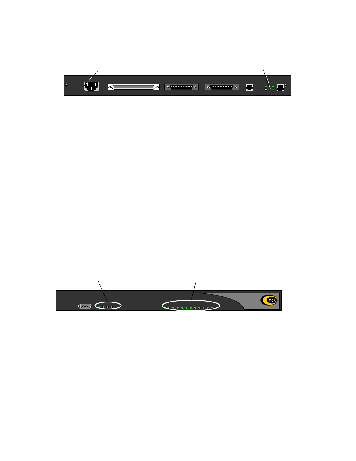
Power-Up
1. Once the VT-100 program is set up, plug the unit into an AC outlet. The device will begin a series of
self-diagnostic tests, which are displayed as a series of LED flashes.
AC Power LAN Connection
VOIP Notes:
The state for the LEDs labeled XMT (Transmit), RCV (Receive), and CLN (Collision) will vary
depending on the status of the network. These LEDs are not critical for verifying the "Power-up
Sequence".
LNK LED Should be solid green.
If you are connecting a PBXgateway to an IP network, the unit needs an assigned IP address.
The Ethernet port on the Remote unit only operates on 10 megabit Ethernet networks. It does not
support 100 megabits.
2. Once the power-up sequence has finished, the state of the following LEDs should be Green.
LED States:
IMPORTANT: If any of the LEDs DO NOT power as explained, refer to the System
Administrator’s Guide for troubleshooting information.
PWR and WAN 1 (Connected) Ports
100-240 V ~ 0.8A 50-60 HZ
TELEPHONY INTERFACE
WAN 1
WAN 2
ANALOG LAN
LNK
0
CLN
XMT LNK
RCV CLN
Figure 3: Back of Unit (for a VOIP connection, see Notes below)
PWR: Solid Green
WAN1: Solid Green (Ready) if a synchronous device is connected to WAN 1.
Solid Orange (Ready) if an asynchronous ISDN TA is connected and accepting
commands (but there is no link up- in Call Suspend mode or have not dialed it yet).
Port LEDs: Solid Green if connected properly to PBX.
LNK
CLN
Console
WAN
PWR 1 32
Reset
Port Status
31 2 8 9 10 11 127654
Figure 4: Front of Unit
PBXgateway Quick Installation Guide 12

On initial power-up (or before the config file has been changed) the Management Interface will display the
following prompt.
Press “Enter” to start the PBXgateway shell…..
Note: If the PBXgateway is powered up prior to opening the terminal program, this message will not
appear.
Do you want to run the “Setup Wizard”
• If you type “Yes”, the wizard will ask a series of configuration questions (see page 16).
• If you type “NO”, you will enter the main Management Interface.
3. Go to Basic Configuration on the next page.
PBXgateway Quick Installation Guide 13

Basic Configuration
1. Press Enter and the Welcome Screen of the Management Interface (MI) will appear.
(see Figure 5)
Figure 5: Welcome Screen
IMPORTANT TERMINAL SETTINGS
The MI requires a screen size of 24 lines X 80 columns. Make sure the Welcome Screen
is bordered on all four sides with a # symbol, as shown in Figure 5.
To enlarge the screen (within the VT-100 application)
Click any corner of the screen.
Drag the screen to enlarge.
Check that the screen is bordered by “#” symbols.
2. Press any key to continue. The Main Menu will appear.
3. If you already familiar with using the MI proceed to the next page for information on setting the
parameters for different Installation Environments.
or
4. Press F1 for the MI Help Screen that provides basic information for navigating through the interface.
PBXgateway Quick Installation Guide 14
 Loading...