

Page 1

G-7000T-RUM Rev AD
August 2004
MCK EXTender™ 7000 for Branch Offices
Installation Guide
Quality is our job. Customer Satisfaction is our mission!
Page 2

Page 3

Copyright Information
Copyright © 2001-2004, MCK Communications, Inc.
All Rights Reserved
Printed in USA September 1, 2004
Notice
Every effort was made to ensure that the information in this book was complete and accurate at the time of printing.
However, information is subject to change.
Your Responsibility for Your System’s Security
Toll fraud is the use of your telecommunications system by an unauthorized party, for example, persons other than your
company’s employees, agents, subcontractors, or persons working on your company’s behalf. Note that there may be a
risk of toll fraud associated with your telecommunications system and, if toll fraud occurs, it can result in substantial
additional charges for your telecommunications services.
You and your system manager are responsible for the security of your system, such as programming and configuring your
equipment to prevent unauthorized use. The system manager is also responsible for reading all installation, instruction,
and system administration documents provided with this product in order to fully understand the features that can introduce
risk of toll fraud and the steps that can be taken to reduce that risk. MCK Communications does not warrant that this
product is immune from or will prevent unauthorized use of common-carrier telecommunication services or facilities
accessed through or connected to it. MCK Communications will not be responsible for any charges that result from such
unauthorized use.
Federal Communications Commission Statement
This equipment has been tested and found to comply with the limits for a Class B digital device, pursuant to Part 15 of the
FCC Rules. These limits are designed to provide reasonable protection against harmful interference when the equipment is
operated in a commercial environment. This equipment generates, uses, and can radiate radio frequency energy and, if not
installed and used in accordance with the instruction manual, may cause harmful interference to radio communications.
However, there is no guarantee that interference will not occur in a particular installation. For further FCC information, see
"Customer Support Information" on page i.
Trademarks
MCK, the MCK logo, MCK EXT ender, PBXgateway , R VP, and RVPoIP are trademarks of MCK Communications, Inc. Other
brand and product names referenced herein are trademarks of their respective holders.
Page 4

EXTender
TM
7000 Installation Guide Page 4
Table of Contents
Copyright Information...................................... ... ... ... .... ... ... ... .... ... ... ... .... ... ... ... ... ........................................ 3
Table of Contents ........................................................................................................................................ 4
Chapter 1:Introduction ............................................................................... 7
Purpose of this Document.......................................................................................................................... 7
Related Documentation ..............................................................................................................................7
Naming Conventions ..................................................................................................................................7
Safety Considerations................................................................................................................................. 8
Service .................................. ....................................... ... ... ... .... ..................................................................8
Specifications .............................................................................................................................................. 9
Regulatory Approvals ..................... ............................................................................................................9
System Architecture ...................................................................................................................................9
Memory .................................... ... ....................................... ... .... ... ... ............................................................9
WAN Ports ......................................... ... ... .... ... ....................................... ... ... ... ... .........................................9
WAN 1 and WAN 2 .............................. .... ...................................... .... ... ... ... ... .... ... ... ...............................9
Internal MCK WAN Card .........................................................................................................................9
Interfaces .................................... ................................. ................................... ..........................................10
Voice Protocols and Services ......... ... ... .......................................... ... .... ...................................................10
Electrical ..................................... ................................................................. .............................................10
Mechanical ...............................................................................................................................................10
Environmental ....................................... ....... ...... ...... ....... ...... ....... ...... ....... ...... ....... ... ................................10
Chapter 2:Connection and Wiring ..........................................................13
Prerequisites for Installation .................................................................................................................... 14
Network Requirements .............................................................................................................................14
Space Requirements ................................................................................................................................14
Supported Telephones.............................................................................................................................. 15
RemoteConneX Phones ...........................................................................................................................15
Avaya Definity ...........................................................................................................................................15
Nortel Meridian .........................................................................................................................................15
Nortel Norstar ...........................................................................................................................................15
EXTender Parts for Installation................................................................................................................ 16
Parts Provided with the EXTender ...........................................................................................................16
Parts Not Provided with the EXTender .....................................................................................................16
Installation Considerations .......................................................................................................................16
Mounting and Connections for the EXTender 7000 ............................................................................... 17
Connections to the EXTender 7000 .........................................................................................................17
Telephony Wiring (RJ-21) ......................................................................................................................... 19
Serial Console Connection and Setup..................................................................................................... 20
Required Cable .........................................................................................................................................20
Enhanced Terminal Interface (ETI) Setup ................................................................................................20
Power-Up.................................................................................................................................................... 22
The Management Interface ....................................................................................................................... 23
Set Up Wizard............................................................................................................................................. 24
Standard Console UI vs. the Setup Wizard ...........................................................................................24
Chapter 3:Configuration ..........................................................................25
RVP_Direct via Leased T1 Line Configuration........................................................................................ 26
Installation .............................................................................................................................................26
Page 5

EXTender
TM
7000 Installation Guide Page 5
Prerequisites for Configuration .............................................................................................................26
Required Configurable Parameters ......................................................................................................26
T1/PRI Port (WAN3) - Leased T1 Parameters .........................................................................................27
Dedicated Service to the DS0 Channel ....................................................................................................28
Assigning DS0 channels: .................................. ... .................................................................................28
RVP_Direct - Leased T1 Parameters ................... .......................... .......................... ................................28
Serial RVP (RVP_Direct) via WAN Configuration ................................................................................... 29
Prerequisites for Configuration .................................................................................................................29
Configuration Steps ..................................................................................................................................29
Connect Parameters - Serial RVP (RVP_Direct) via WAN ......................................................................30
WAN Port Setup .......................................................................................................................................31
Setting the Sync Rate ..............................................................................................................................32
Setting the Mode (Signaling Protocol) ......................................................................................................32
Setting the Interface Type ........................................................................................................................33
..............................................................................................................................................................33
RVP_Direct via PRI Configuration ........................................ .... ... ... ... .... ... ... ... ......................................... 34
Installation ................................................................................................................................................34
Prerequisites for Configuration .................................................................................................................34
Required Configurable Parameters ................................ .......................... .......................... ......................34
RVP_Direct Parameters - PRI .... .... ... ... ... ....................................... ... .... ... ... ... ... .... ... ................................35
T1/PRI (WAN3) Settings - PRI ....................................................... ... .... ... ... ... ... .... ... ... .............................35
Channel Setup - PRI ................................................................................................................................36
Assigning DS0 Channels .. ... ... .... ... ... ... .... ... ..........................................................................................36
Entering Primary Dial Numbers ................................................................................................................37
Set the T1/PRI Service Parameters .........................................................................................................37
RVP Over IP Configuration....................................................................................................................... 38
Prerequisites for Configuration .................................................................................................................38
TCP/UDP Requirements .......................... ... ... .......................................................................................38
RVP_IP - Configuration ............................................................................................................................39
Connect Parameters - RVP_Over_IP ......................................................................................................39
IP Parameters ..........................................................................................................................................41
Setting the Network IP Addresses ........................................................................................................41
RVP_Over_Frame Relay Configuration................................................................................................... 43
Prerequisites for Configuration .............................................................................................................43
Frame Relay Connect Parameters ...........................................................................................................44
Setting the Interface Parameters ..........................................................................................................44
Setting the Frame Relay PVC Parameters ....... ... .................................................................................46
T1/PRI Port (WAN3) Frame Relay Parameters .......................................................................................47
Dedicated Service to the DS0 Channel ....................................................................................................48
DSO Channel Assignment Options ................ ... ... .... ... ... ... .... ... ... ... .... ... ... ... ... .... ...................................48
Assigning DS0 Channels .. ... ... .... ... ... ... .... ... ............................................................................
..............48
Verifying Frame Relay Parameters ..........................................................................................................49
Chapter 4:Applications ............................................................................51
Add/Drop Application................................................................................................................................ 52
Add/Drop Configuration ............................................................................................................................52
WAN Port Setup ....................................................................................................................................52
Enabling Add/Drop Service ...................... ... ... ... ... .... ... ... ... .... ... .............................................................52
Add/Drop Configuration for T1 Leased ....................................................................................................53
Add/Drop - T1/PRI Port (WAN3) - Leased T1 Parameters ...................................................... ... .... ... ...53
Add/Drop Channels - Leased T1 Parameters .......................................................................................54
Add/Drop PVC - T1 Frame Relay .............................................................................................................55
T1/PRI Port (WAN3) Configuration - T1 Frame Relay .......................................................................... 55
Please refer to “Add/Drop - T1/PRI Port (WAN3) - Leased T1 Parameters on page’ 53. .....................55
Assigning Add/Drop PVC ..................... .... ... ... ... ... .... ...................................... .... ... ... ... .... ... ... ................55
Page 6

EXTender
TM
7000 Installation Guide Page 6
2 to 1 RVP_Over_IP with Local Dialing Configuration ........................................................................... 57
2:1 RVP_Over IP Consideration ................. ... .......................................................................................57
2:1 Configuration - Computing the Required Bandwidth ..........................................................................58
EXTender Bandwidth Requirements .....................................................................................................59
Identifying the EXTender 7000 to the PBXgateway II ...........................................................................59
De-hairpinned Calls ...............................................................................................................................60
Setting the Local Dialing Parameters .......................................................................................................61
RVPoIP Limitations ........................................................ ... .... ... ... ..........................................................61
2:1 Specific - Local Dialing Configurations ...........................................................................................61
Synchronizing the MCK T1/PRI card with the Central Office ...................................................................62
Configuring the T1/PRI Port for Local Dialing .......................................................................................62
Identifying the Local Trunk Port ................................................................................................................63
Local Dialing Configurations.................................................................................................................... 66
Local Hosted Calling (via Predefined Local Trunk Key) .... ... .... ................................................................66
PBX Hosted Calling ..................................................................................................................................66
Local Dialing Via PRI ..... .... ... ... ... .... ... ... ... .... .............................................................................................66
Setting the Local Trunk Parameters ...................................... ............................. ...................................67
Set the Local Dialing Parameters ..........................................................................................................67
Key Mapping .........................................................................................................................................68
Default Local Dialing Setup ...................................................................................................................68
Network Termination (Dual T1/PRI Lines) ............................................................................................... 70
CSU/DSU Functionality ........... .... ... ... ... .... ... ... ... ....................................................................................70
Separate PRI Configuration...................................................................................................................... 71
Installation .............................................................................................................................................71
Prerequisites for Configuration ..............................................................................................................71
Configuring Caller ID ................................................................................................................................73
Chapter 5:Quick Setup ............................................................................. 76
EXTender 7000 - Quick Setup................................................................................................................... 77
Leased Line/Point-to-Point T1 ..................................................................................................................77
Enabling the PRI Port ............................................................................................................................77
Setting DSO Default Parameters ..........................................................................................................77
RVP_Direct Settings .............................................................................................................................78
Local Dialing via PRI ................................................................................................................................78
Setting the DSO Default Parameters ....................................................................................................78
Setting Local Dialing Parameters .......................................... ................................................................79
Key Mapping .........................................................................................................................................79
Default Local Dialing Setup ...................................................................................................................80
Add/Drop Setup .... ... ... ... .... ... ... ... .... ...................................... .... ... ... ... .... ... ... ... ..........................................81
Index ........................................................................................................................................................... 84
Page 7

EXTender
TM
7000 Installation Guide Page 7
Chapter 1: Introduction
Purpose of this Document
This document provides the step-by-step process for the complete installation, basic configuration, and
troubleshooting of the EXTender 7000 for Branch Offices.
Related Documentation
In addition to this document, you should have the following:
• PBXgateway II System Administrator’s Guide
• PBXgateway II Installation Guide
• EXTender 7000 User’s Guide
Naming Conventions
The EXTender 7000 is also referred to as the EXTender or the Remote Unit within this document.
Page 8

EXTender
TM
7000 Installation Guide Page 8
Safety Considerations
IMPORTANT SAFETY INSTRUCTIONS
• Do not install this product near water.
Example
: In a wet basement location.
• Do not overload wall outlets, as this can result in the risk of fire or electrical shock.
• Do not attach the power supply cord to building surfaces. Do not allow anything to rest on the power
cord. Do not locate this product where persons walking on it will abuse the cord.
• Do not operate the system if chemical gas leakage is suspected in the area. Use telephones located in
some other safe area to report the trouble.
Service
Call MCK Customer Support at 1-888-454-5828 between 8:30a.m. and 8p.m. Eastern Standard Time (EST)
or your local MCK Communications representative if you need assistance when installing, programming, or
using this product. Outside of North America please dial 1-617-454-6192.
For installation and maintenance options, please cont act your MCK reseller . For information on MCK service
offerings, please go to MCK’s website at www.MCK.com and visit the Service & Support section.
!
Page 9

EXTender
TM
7000 Installation Guide Page 9
Specifications
Regulatory Approvals
System Architecture
Memory
WAN Ports
WAN 1 and WAN 2
Internal MCK W AN Card
FCC Part 15, Subpart B, Class A
Part 68, Subpart D (Only required when network interface expansion
cards are added.)
CA NRTL/C CAN/CSA-C22.2 No. 950-93
CAN/CSA-C22.2 No. 225-M90
UL Std. No. 1459
UL Std. No. 1950-95
CE Mark EN50081-1, EN50081-2, EN55022 Class A
BABT 90/002 S/R2 CTR 3/A1 (Only required when network interface expan-
sion cards are added.)
Industry Canada CS-03 Part 1 Issue 8 (Only required when network interface expan-
sion cards are added.)
UL Standard 950
CPU Motorola MPC860T
DSP Five Analog Devices 2185 (52 MIPS)
DRAM 16MB
Flash Memory 16MB
Boot ROM 512KB
Protocol Synchronous serial
Interface RS-232, V.35, or RS-530
Encapsulation High level Data Link Control (HDLC)
Interface Two RJ-48C ports
Encapsulation High level Data Link Control (HDLC)
Page 10

EXTender
TM
7000 Installation Guide Page 10
Interfaces
Voice Protocols and Services
Electrical
Mechanical
Environmental
Analog One RJ-11 port
Ethernet Two 10/100BaseT, RJ-45 ports
Serial/WAN Two DB-25 ports: EIA/TI232, EIA/TI530, EIA/TIAV35
Serial/Console Two Serial RS-232, DB-9 ports
PBX/KTS Up to 24 digital line interfaces over a 25 pair RJ-21 cable
T1/PRI Two RJ-48C ports in the integrated MCK WAN card
Voice compression G.729a, G.711, ADPCM 32, ADPCM 24
WAN, T1
Remote Voice Protocol (RVP
TM
)(proprietary) over
HDLC
LAN RVP over Internet Protocol (IP)
Line Voltage 100-240 VAC
Frequency 50-60 Hz
Max Power Consumption 0.8 Amps
Power Input Filter IEC (with 2A fuse)
Dimensions 17” x 10 3/4” x 1 3/4” (432mm x 203mm x 44mm)
Weight 6 lbs 7oz (3kg)
Temperature 32° - 130°F (0° - 55°C)
Relative Humidity 5 to 95%
Page 11

EXTender
TM
7000 Installation Guide Page 11
Page 12

EXTender
TM
7000 Installation Guide Page 12
Page 13

EXTender
TM
7000 Installation Guide Page 13
Chapter 2: Connection and Wiring
The following chapter will provide you with instructions on accessing the Management Interface (MI) via the
following methods: Direct Connect (Serial Modem) to DB9, Terminal Interface - Hyperterminal (TI), Telnet,
and Internet.
Page 14

EXTender
TM
7000 Installation Guide Page 14
Prerequisites for Installation
The following items are required before installing the EXTender.
Network Requirements
• The MCK T1/PRI card provides network termination. If you choose not to use the MCK T1/PRI card, you
must make sure the appropriate network terminating devices are installed , con figured, and functioning
at both the corporate facility and the branch office. These ne twork devices must support one of the following:
• an RS-232, V.35, or RS-530 synchronous serial interface
• a Voice over IP (10/100BaseT) interface
• Connect the Remote unit to the phones using proper wiring with adequate pu nch down blocks. Use “Pin
Assignments (25-Pair Cable) on page’ 19 as a guide, and provide the RJ-21 female connector.
• Branch Office T1 / PRI Provisioning for Local Dialing
• DTMF signaling (can be pulse)
• *Wink (received) immediate (transmit out) start
• B8ZS coding
• ESF framing
• You can use the default DS0 DN or select them individually and indicate how the line will perform
(i.e Incoming/Outgoing).
*Wink / Immediate essentially means that for outbound calls our CSU/DSU needs Wink Start and for
inbound calls Immediate Start. For outbound Wink start, our CSU/DSU will seize the line and wait for
the network to send a wink. After receiving the Wink the CSU/DSU will then start pulsing out the digits. For inbound calls, the network should just seize the line. The CSU/DSU does not accept inbound
digits and will not produce a wink.
• If using a PRI ensure that the circuit has been provisioned by the Telcos to include NO NFAS and if
needed DID provided. This way we can assign inbound calls on the local PRI to specific phones on the
EXTender 7000.
Space Requirements
• The distance from the phones to the EXTender should NOT exceed 500 feet.
Page 15

EXTender
TM
7000 Installation Guide Page 15
Supported Telephones
The following digital display phones are compatible with the EXTender.
RemoteConneX Phones
Astra 390 ADSI-compliant Interactive sceen phones (for RemoreConneX features)
Avaya Definity
* This digital display phone is NOT recommended for administrative purposes.
Nortel Meridian
* These digital display phones are NOT recommende d for administrative purposes.
Nortel Norstar
* This digital display phone is NOT recommended for administrative purposes.
** Line appearances must be set to keys 0-15 for Local Dialing capability.
*6402+ 8403 9031DCP CallMaster III
6408+ 8410D 9040 TransTalk CallMaster IV
6416D+
6416M
8410DR Any DTMF-
enabled mobile
phone
CallMaster V
6424D+
6424M
8434DX CallMaster VI
*M2006 **M2616CT M3904
*M2008 *M3901 M3905
M2216 M3902 Any DTMF-enabled
mobile phone
M2250 M3903
M2616 M2112 M7208
*M7100 M7310 T7316
M7208 M7316 M7410
*T7208 **M7324 ATA2
M7308 *T7216 Any DTMF-enabled
mobile phone
Page 16

EXTender
TM
7000 Installation Guide Page 16
EXTender Parts for Installation
Parts Provided with the EXTender
Parts Not Provided with the EXTender
• Digital telephones and communication line cords are NOT supplied with this system.
Note: Use two-wire digital display phones only.
• Punch down blocks necessary to interface between the RJ-21 connector and the remote phones.
• 50 pin cable with male RJ-21 connectors to interface between the punch down block and the EXTender.
(see “Pin Assignments (25-Pair Cable) on page’ 19.)
Note: The RJ-21 cable can be ordered through MCK.
• Analog telephone line for 911emergency calls.
Note: The analog line card is not available outside North America.
Installation Considerations
• The system has been designed to operate from 100-240 VAC, 50-60Hz. Power should not be applied to
the unit until specified in the installation procedures.
• Use good wiring practices. Do not install the EXTender or its cabling near high power/high RF noise
devices such as flourescent ballasts or power supplies.
Table 1: Parts Provided with the EXTender
Qty
Description
1
EXTender 7000
1
Power Cord
1
a DB-25M to DB-25F RS-530 serial cable (shipped without a T1 Card)
or a DB-25F to DB-25F RS-530 serial, crossover cable ( shipped with a T1 Card
or for add/drop traffic)
1
DB-9 RS-232 serial cable
1
RJ-45 Cat 5 Ethernet cable
-
Mounting Hardware
2
Mounting Brackets (2)
1
Installation Guide
1
User’s Guide
1
User Documents CD
1
Warranty Registration Card
Page 17
EXTender
TM
7000 Installation Guide Page 17
Mounting and Connections for the EXTender 7000
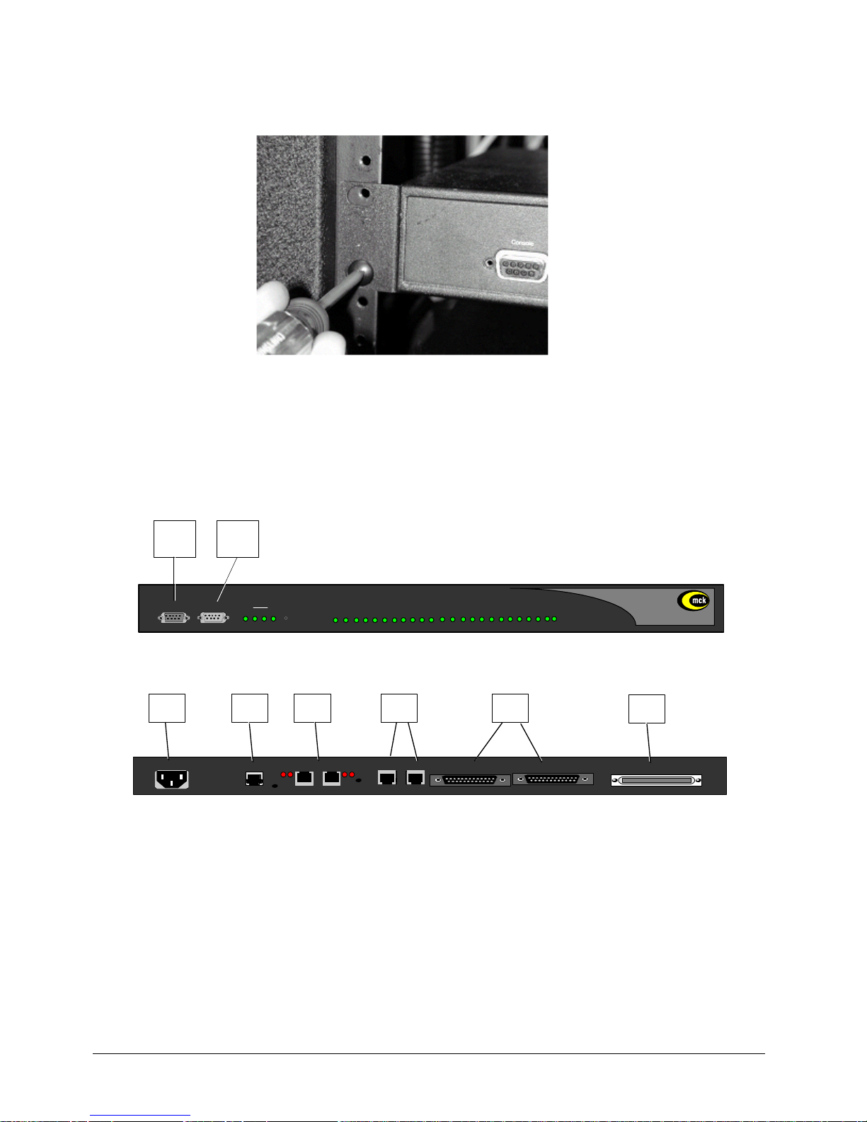
The EXTender can be mounted in a standard 19-inch communication rack using the hardware provided or
simply placed on a shelf within the rack.
Figure 2-1: Securing the Unit to a Rack
Connections to the EXTender 7000
The EXTender provides connections A through H, as shown below:
Note: Connection “G” is only used for synchronous serial, and “D” is used for connection to an analog
line.
Figure 2-2: Front of Unit
Figure 2-3: Back of Unit
SWITCH
UNIT
1 2 AN
Console Modem
WAN
Reset
Port Status
1 2 3 4 5 6 7 8 9 10 11 12 13 14 15 16 17 18 19 20 21 22 23 24
EXTender 7000
A B
PWR
LNK
CLN
LAN
0
WAN 1
WAN 2
100-240 V ~ 1.4A MAX 50-60 Hz
NETWORK INTERFACE
TELEPHONY INTERFACE
LNK ACT LNK ACT
Aux LAN LAN
C
D
E F G
H
Port 1 Port 2
Page 18

EXTender
TM
7000 Installation Guide Page 18
Table 2: EXTender 7000 Connections
Letter Label Cable Type Description
A Console DB-9 Direct serial connection to a PC for administration.
(DCE)
See “Serial Console Connection and Setup on page’ 20.
Note: Set the COM port as follows; Baud rate: 9600,
Databits: 8, Parity: none, Stopbits: 1, Software flow control: XON/XOFF
B Modem DB-9 Direct serial connection to a modem for remote access.
(DTE).
Note: Set the COM port as follows; Baud rate: 9600, Databits: 8, Parity: none, Stopbits: 1, Software flow control:
XON/XOFF
C 100-240V Power Connect to a 120VAC outlet.
Connect as the last step (see “Power-Up on page’ 22.)
DANALOG
(in North
America only)
RJ-11 Connects to an analog line for local dialing. The port will
only support a dedicated analog circuit.
Note: This port will not provide PBX functionality or features.
E Network Inter-
face/WAN3
Expansion
Port
If purchased, the MCK T1/PRI card will be installed here.
The MCK T1/PRI card has two RJ-48C ports which terminate T1, FT1, and PRI lines.
F
LAN
RJ-45 Ethernet
(10/
100baseT)
Used for connecting the unit to the LAN for use in Voice
over IP (RVP_IP) applications.
Aux LAN
RJ-45 Ethernet
(10/
100baseT)
Used for administrative purposes. (Telnet, FTP and
HTML)
G
WAN1
WAN2
DB-25,
serial,
straightthrough
Used for a synchronous serial connection. Connect to a
FRAD, CSU/DSU, or other network device.
Note: An RS-530 type cable or DB-25 to M34 cable
should be used for high-speed links to V.35 equipment.
DB-25,
serial, crossover
Used for Add/Drop Traffic .
H
Telephony
Interface
RJ-21 (CAT 3)Wire to a punch down block and then to the telephones.
(see“Pin Assignments (25-Pair Cable) on page’ 19)
Page 19

EXTender
TM
7000 Installation Guide Page 19
Telephony Wiring (RJ-21)
Wire Color Abbreviations:
BK=Black BR=Brown RD=Red OR=Orange SL=Slate
YL=Yellow GN=Green BL=Blue VI=Violet WH=White
Table 3: Pin Assignments (25-Pair Cable)
Pin Cable
Pair
Port Pin Cable
Pair
Port
26
1
WH/BL
WH/BL
13813GN/BK
BL/GN
13
27
2
WH/OR
WH/OR
23914BK/BR
BK/BR
14
28
3
WH/GN
WH/GR
34015BK/SL
BK/SL
15
29
4
WH/BR
WH/BR
44116YL/BL
YL/BL
16
30
5
WH/SL
WH/SL
54217YL/OR
YL/OR
17
31
6
RD/BL
RD/BL
64318YL/GN
YL/GN
18
32
7
RD/OR
RD/OR
74419YL/BR
YL/BR
19
33
8
RD/GN
RD/GN
84520YL/SL
YL/SL
20
34
9
RD/BR
RD/BR
94621VI/BL
VI/BL
21
35
10
RD/SL
RD/SL
10 47
22
VI/OR
VI/OR
22
36
11
BK/BL
BK/BL
11 48
23
VI/GN
VI/GN
23
37
12
BK/OR
BK/OR
12 49
24
VI/BR
VI/BR
24
50
25
VI/SL
VI/SL
GND
Page 20
EXTender
TM
7000 Installation Guide Page 20
Serial Console Connection and Setup
The Console port on the front of the EXTender provides a direct serial connection to your computer. Through
this port, you can access all of the features and functions of the MI, as well as configure, monitor, and troubleshoot the unit.
Required Cable
You need a standard RS-232 serial straight-through (DB-9, Male) cable. Use this cable to connect the PC’s
COM Port to the port labeled “Console” on the fron t of the un it.
Note: Cable length should not exceed 50 ft.
Before connecting to the EXTender you must confirm that the PC’s COM port settings match the console
port settings as follows:
After you have connected the EXTender to the PC, see “Enhanced Terminal Interface (ETI) Setup on page’
20.
Enhanced Terminal Interface (ETI) Setup
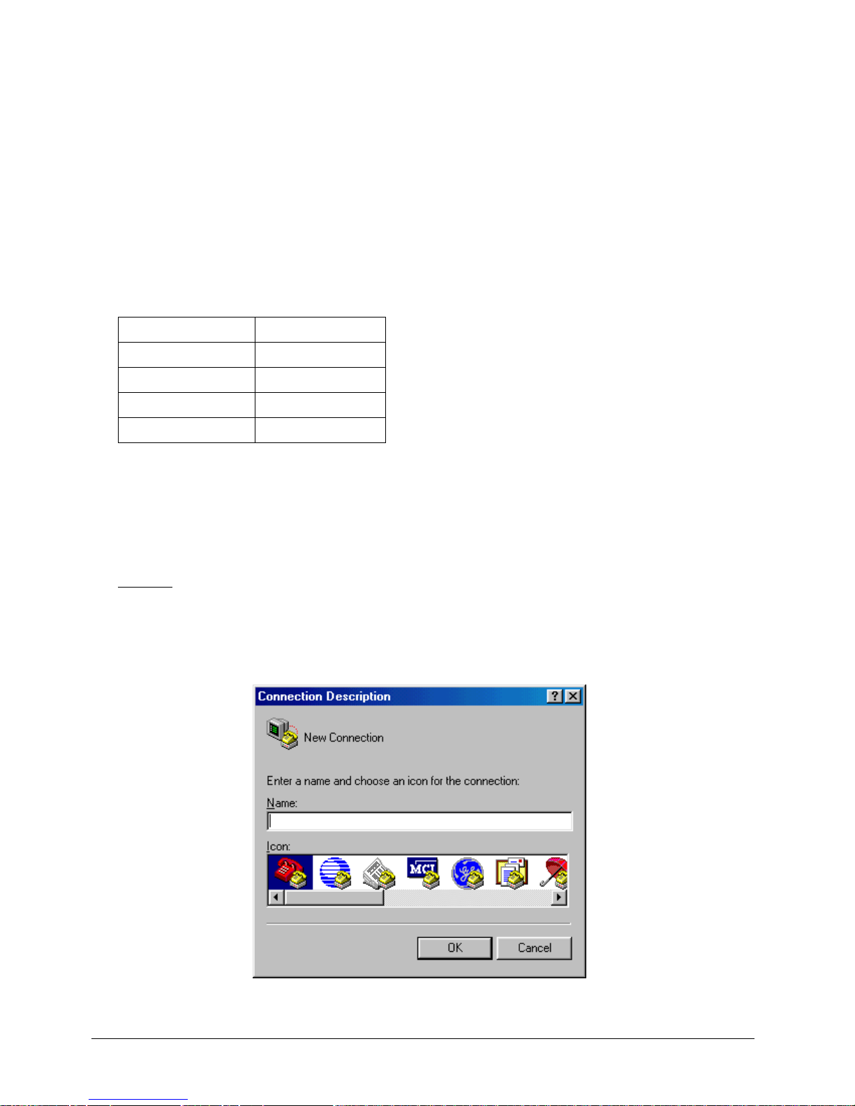
1. Once the PC or modem is connected to the EXTender through the console port, open an Enhanced Terminal Interface (ETI) program on the PC.
Example
: Windows HyperTerminal
Note: The Management Interface (MI) configuration menus can be accessed through any generic Windows 95 or Windows 98, VT-100 Enhanced Terminal Interface (ETI) program.
2. After HyperTerminal is started, the Connection Description dialog box appears:
Figure 2-4: Connection Description
Baud rate 9600
Databits 8
Parity none
Stopbits 1
Flow Control XON/XOFF
Page 21
EXTender
TM
7000 Installation Guide Page 21
3. Enter a name for your session and select a corresponding icon. This enables you to quickly connect to
the EXTender 7000 in the future.
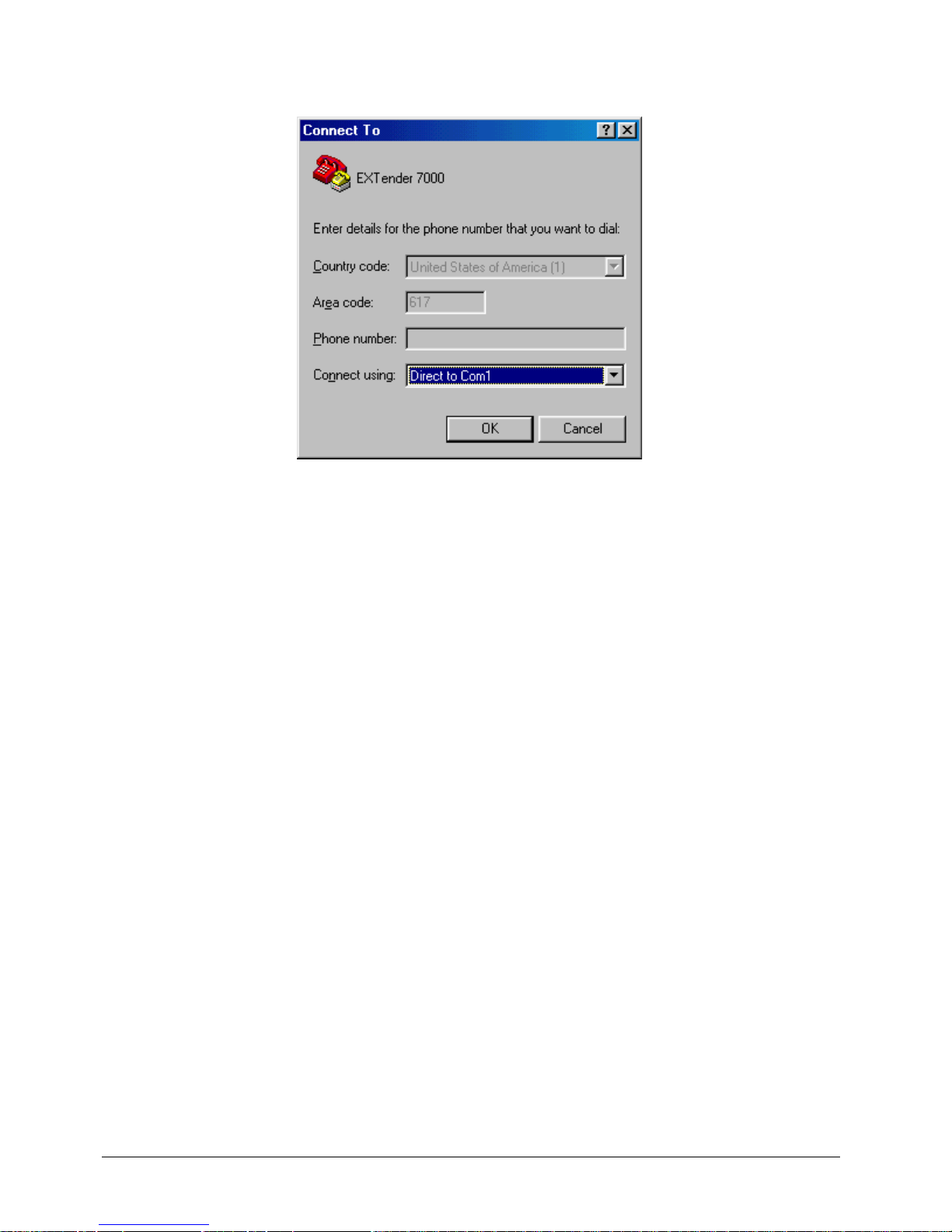
4. Click on the OK button. The Connect To dialog box appears:
Figure 2-5: Connect To Dialog Box
5. In the Connect using: box, select the COM port that is connected to the Console port on the EXTender
7000 via the RS-232 cable.
6. Click on the OK button. The Port Settings for the COM port you selected appear.
7. Select the values in each field to match those shown on page 20.
8. Click on the OK button.
9. Save the changes within the ETI and restart the program for the changes to take effect.
10. Power up the EXTender 7000. The unit performs a series of boot-up tests and upon finishing the bootup process, displays the following message:
Press “Enter” to start the shell…………….
IMPORTANT NOTE: If the unit is already powered-up the screen may display garbage characters.
Press F4 (or Ctrl+R) to refresh the screen.
11. Press Enter. The MI Welcome Screen appears (see page 23).
Page 22
EXTender
TM
7000 Installation Guide Page 22
Power-Up
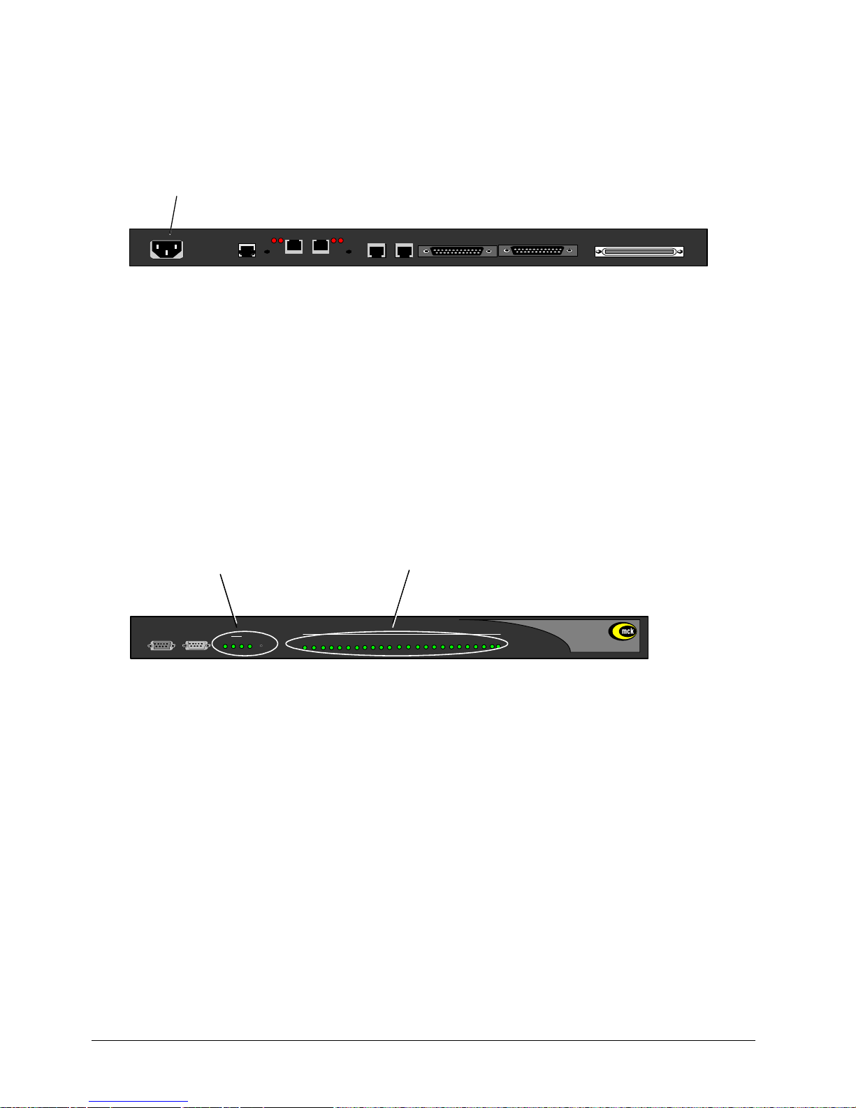
1. Once the VT-100 program is set up, plug the unit into an AC outlet. The device will begin a series of selfdiagnostic tests, which are displayed as a series of LED flashes. During the power-up sequence,
observe the Power, WAN and Port LEDs on the front of the EXTender.
Figure 2-6: Back of Unit
VOIP Notes:
• If you are connecting an EXTender to an IP network, the unit needs to be assigned an IP address.
• Once the power-up sequence has finished, the state of the following LEDs should be Green.
LED States:
PWR: Solid Green
WAN 1: Solid Green (Ready) if a synchronous device is connected to WAN 1.
Port LEDs: Solid Green if connected properly to the telephones.
IMPORTANT: If any of the LEDs DO NOT power as explained, refer to the System Administrator’s
Guide for troubleshooting information.
Figure 2-7: Front of Unit
On initial power-up (or before the configuration file has been changed) the Management Interface will ask
you to run the “Setup Wizard” to select the proper PBX/KTS protocol.
• If you type “Yes” the wizard will ask you to select the PBX type.
• If you type “No” the PC displays the following message:
Press “Enter” to start the shell…..
Note: If the EXTender is powered up prior to opening the terminal program, this message will not
appear.
2. Go to “The Management Interface on page’ 23.
PORT 1 PORT 2
LNK
CLN
LAN
0
WAN 1
WAN 2
100-240 V ~ 1.4A MAX 50-60 Hz
TELEPHONY INTERFACE
LNK ACT LNK ACT
AUX LAN LAN
AC Power
NETWORK INTERFACE
PORT 1 PORT 2
SWITCH UNIT
Reset
Port Status
1 2 3 4 5 6 7 8 9 10 11 12 13 14 15 16 17 18 19 20 21 22 23 24
EXTender 7000
PWR and WAN
(Connected) Ports
1 2 ANPWR
WAN
Console Modem
Page 23
EXTender
TM
7000 Installation Guide Page 23
The Management Interface
The Management Interface (MI) is a computer interface used to administer and configure the EXTender
7000 and PBXgateway II. Detailed instructions for using the MI can be found in the EXTender 7000 User’s
Guide.
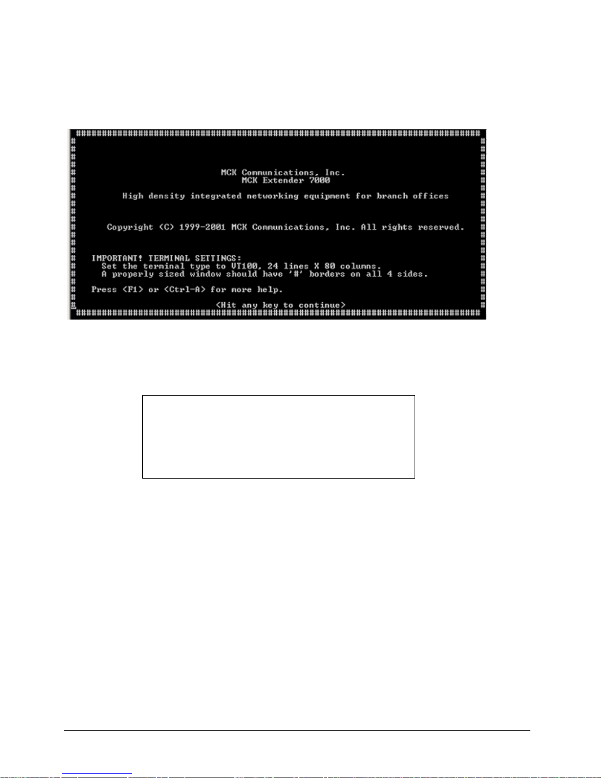
1. Press Enter and the Welcome Screen of the Management Interface (MI) will appear.
Figure 2-8: MI Welcome Screen
IMPORTANT TERMINAL SETTINGS
The MI requires a screen size of 24 lines X 80 columns. Make sure the Welcome Screen is bordered on all
four sides with a # symbol, as shown in the figure above.
2. Press any key to continue. The Main Menu will appear.
3. If you are already familiar with using the MI, proceed to the User’s Guide for information on setting the
parameters for the different networ k environments.
OR
4. Press F1 for the MI Help Screen, which provides basic information for navigating through the interface.
To enlarge the screen (within the VT-100 application)
Click any corner of the screen.
Drag the screen to enlarge.
Check that the screen is bordered by “#” symbols.
Page 24
EXTender
TM
7000 Installation Guide Page 24
Set Up Wizard
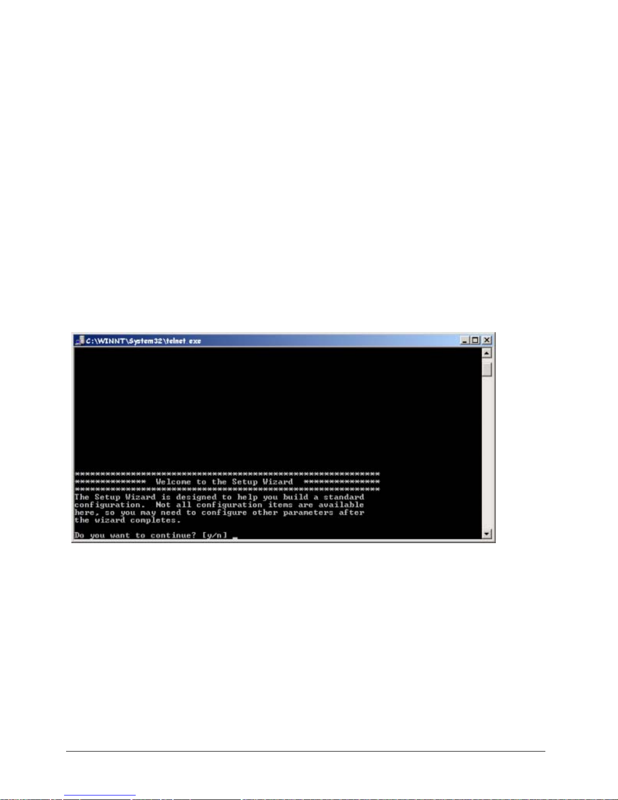
The EXTender provides a console setup wizard which will guide a user through the required programming/
configuration steps required to complete the initial setup of the unit. The Setup Wizard is accessed via the
VT100 console management interface accessed through the DB-9 management port. This will require a PC
running a Terminal Emulation program.
The wizard asks the user the basics of their particular configuration, and uses this information to establish
the initial configuration programming. Parameters that cannot be configured through the wizard can be set
through the Management Interface (MI).
Standard Console UI vs. the Setup Wizard
When a unit is first powered up it will check a Setup Wizard flag. If the flag is set then the standard console
UI will be displayed. If the flag is not set then the user will be asked whether they would like to run the Setup
Wizard. After this initial prompt the Setup Wizard flag will be set, preventing the user from being asked to run
the Wizard again. The Setup Wizard can also be accessed through the console Management Interface in
case the user wants to run it later.
How to access the Setup Wizard through the MI:
MI Path
Remote->Utilities->Setup Wizard
Figure 2-9: Setup Wizard
Page 25

EXTender
TM
7000 Installation Guide Page 25
Chapter 3: Configuration
The following chapter will provide you with instructions on configuring the Extender 7000 via the Management Interface (MI).
The units are programmed at the factory with “default” settings providing basic par ameters to acco mmodate
most network environments.
Page 26
EXTender
TM
7000 Installation Guide Page 26
RVP_Direct via Leased T1 Line Configuration
This section describes configuring the EXTender 7000 for a basic Serial RVP installation using the T1/PRI
Ports on the MCK T1/PRI card.
Note: If you want to add Local Dialing capability to this configuration, see the EXTender 7000 User’s Guide
for complete setup instructions. Leased Line T1 and Point-to-Point T1 configurations are identical.
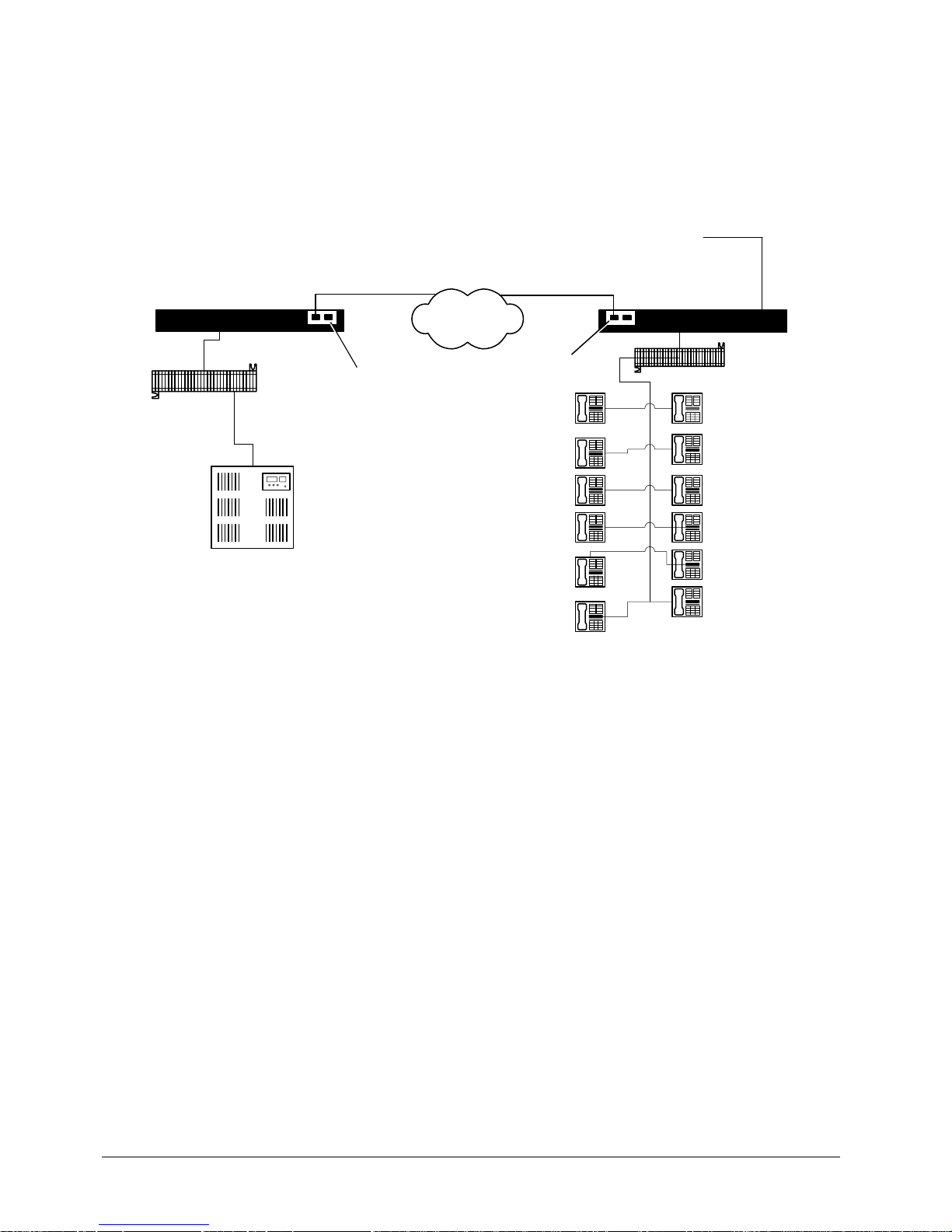
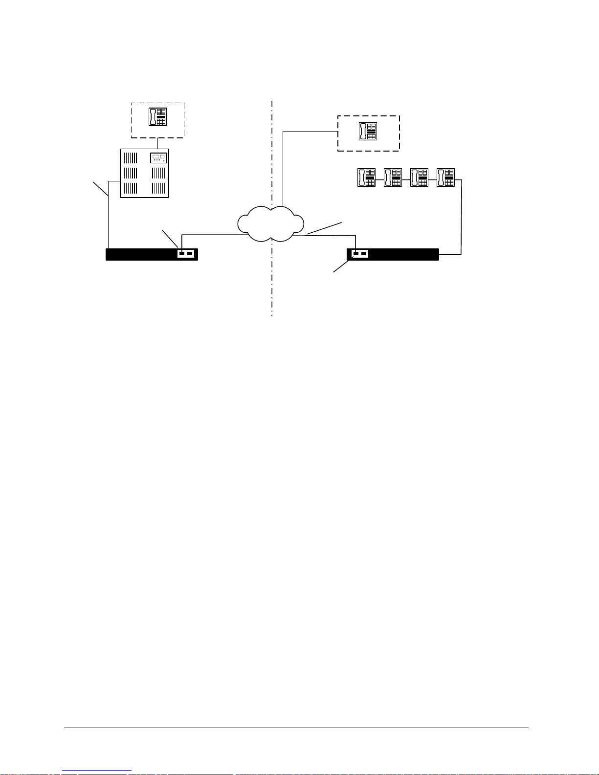
After installation your system should be connected as shown in the figure below:
Figure 3-1: Serial RVP Installation via T1
Installation
• Connect a straight-through T1 cable from the network to the port labeled Port 1 on the MCK T1/PRI card
on the EXTender 7000.
• Connect a straight-through T1 cable from the network to the port labeled Port 1 on the MCK T1/PRI card
on the PBXgateway II.
Prerequisites for Configuration
• The PBXgateway II (at the corporate site) and the EXTender (at the branch office) must be installed
properly and the network link between both devices must be operational.
• The T1/PRI Port Setup parameters for the PBXgateway II must be set to match the corresponding
parameters on the EXTender.
Required Configurable Parameters
• RVP_Direct Parameters - Please see “RVP_Direct - Leased T1 Parameters on page’ 28.
• T1/PRI (WAN3) - Please see “T1/PRI Port (WAN3) - Leased T1 Parameters on page’ 27.
• Channel Setup - Please see “Dedicated Service to the DS0 Channel on page’ 28.
• Local Dialing - Please see “Local Dialing Via PRI on page’ 27.
PSTN
Branch Office
Punch Block
Analog Phone Line
EXTender 7000
Punch Block
PBX
Corporate Office
PBXgateway II
T1/PRI Card
T1/PRI Card
Page 27
EXTender
TM
7000 Installation Guide Page 27
T1/PRI Port (WAN3) - Leased T1 Parameters
This section provides instruction for the configuration of the Leased TI line that is connecting the EXTender
7000 to the Gateway.
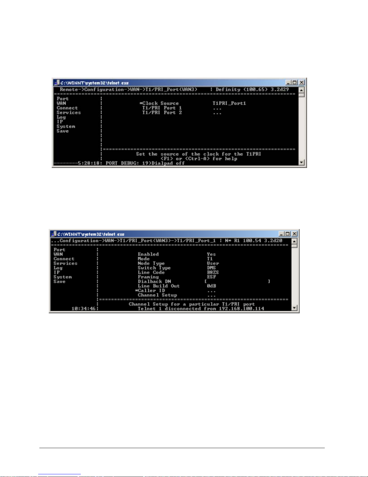
1. Set the Clock Source parameter to T1PRI_Port1.
• Set to Port 1 if the network is providing timing, or Port 2 to use the EXTender 7000 for the timing
source. Note: Point-to -Point (RVP_Direct) T1’s DO NOT provide timing.
Figure 3-2: Clock Source
2. Go to the T1/PRI Port Setup Menu to perform the basic setup for the T1/PRI ports and channels. This
menu is located in the WAN submenu structure, and can be accessed using the following path:
MI Path
Configuration->WAN->T1/PRI_Port(WAN3)->T1/PRI_Port_1
The following menu appears:
Figure 3-3: T1/PRI Port (WAN3) Paramet ers
3. Set the Enabled parameter to Yes.
4. Set the Mode parameter to T1.
5. Ignore the following parameters, as they do not apply to Leased T1 configurations: Node Type, Switch
Type, and Dialback DN.
6. Set the Line Code and Framing parameters with values provided by the Telco company (CO).
7. Select a value for the Line Build Out parameter to attenuate the signal before it leaves the extender.
Use a value recommended by the Telco company (CO).
Page 28
EXTender
TM
7000 Installation Guide Page 28
Dedicated Service to the DS0 Channel
Assigning DS0 channels:
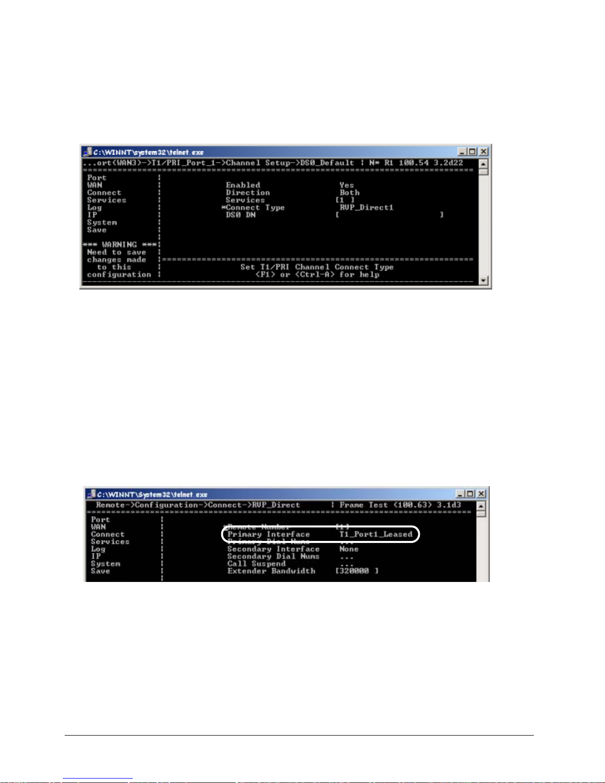
1. Use the arrow keys to access the DS0_Default Channel Setup menu, as shown below:
MI Path
Configuration->WAN->T1/PRI_Port(WAN3)->T1/PRI_Port_1-> Channel Setup-
>DS0_Default
Figure 3-4: Assigning DS0 Channels
2. Set the Enable parameter to Yes.
3. Set Direction to Both.
4. Enter 1 into the Services parameter . This p arameter enables you to select the services yo u wish to use
to connect to the Central Office (CO). The value of 1 assigns a Dedicated T1 Service to all DS0 channels.
5. Set the Connect Type to RVP_Direct1.
RVP_Direct - Leased T1 Parameters
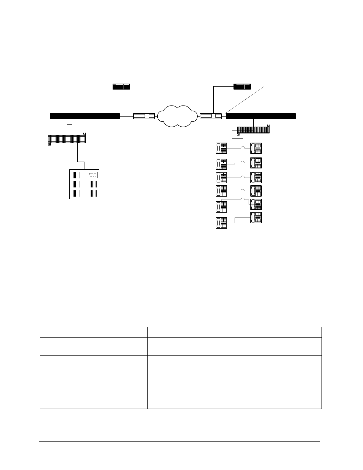
1. Access the RVP_Direct Menu using the following path:
MI Path
Configuration->Connect->RVP_Direct
The following menu appears:
Figure 3-5: RVP_Direct Menu (Leased TI)
2. Set the Primary Interface to T1_Port1_Leased.
3. The EXTender Bandwidth does not have to be set. RVP_Leased T1 uses the number of RVP_Direct1
DS0 channels assigned in Channel Setup as the 'Extender Bandwidth.
4. Press the ← key to accept chan ge s an d go back to th e Con fig u ra tio n Me n u.
T1/PRI Port_1 should now be sync up with the Networ k att ached a nd th e LED on th e T1/PRI port sho uld be
steady Green. This is assuming the Gateway has also completed the configuration setup; and with a steady
Green LED on the T1/PRI Port_1. The User can now connect phones by pressing '1.
Page 29
EXTender
TM
7000 Installation Guide Page 29
Serial RVP (RVP_Direct) via WAN Configuration
The following pages provide step by step instructions for configuring a basic Serial RVP installation using
the WAN ports of the EXTender 7000. To configure the system, you will set various parameters in the Management Interface (MI). For more information please refer to the EXTender 7000 User’s Guide.
After installation, your system should be connected as shown in the figure below:
Figure 3-6: Serial Installation via WAN Ports
Prerequisites for Configuration
• The PBXgateway II (at the corporate site) and the EXTender (at the branch office) must be installed
properly and the network link between both devices must be operational.
• It is recommend that the network administrator assign an IP addr ess for both unit s for re mote co nfiguration and administration.
Configuration Steps
You must ….…… to………… Default settings
Set Connect Parameters
Select the network type and set parameters
relating to that network type.
RVP Direct
Setup the WAN ports
Enable WAN ports to connect to network
device.
WAN 1 - Enabled
Set the Sync Rate of the WAN port
Match the data rate (sync rate) of the network device.
512,000 kbps
Set the mode (interface type) of the
WAN port. (v.35, RS-232, RS-530)
Match the interface type of the network
device.
Sync-V.35
Punch Block
Public
DSU/CSUDSU/CSU
PBX
Branch Office
Corporate Facility
Punch Block
PBXgateway II
EXTender 7000
CSU/DSU
Connects via
WAN Port
Router
Router
Page 30
EXTender
TM
7000 Installation Guide Page 30
Connect Parameters - Serial RVP (RVP_Direct) via WAN
The EXTender utilizes a direct serial connection to provide remote user connectivity. This means that the
WAN port is plugged directly into a network device. The WAN port (WAN 1 or WAN 2) that is used as the
main or “primary” port must be identified on the RVP Direct menu.
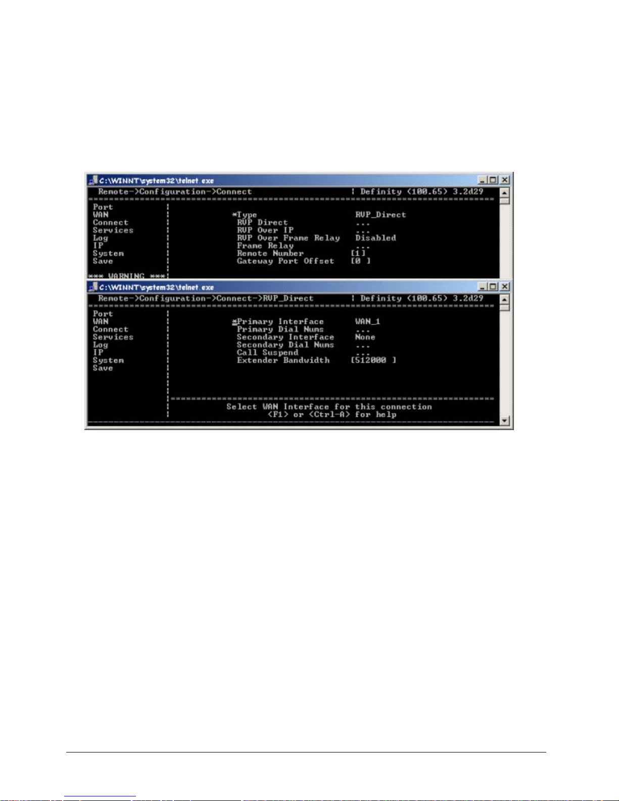
1. Access the Connect Menu using the following MI path:
MI Path
Configuration->Connect
The following menu appears:
Figure 3-7: Serial RVP via WAN Configuration - RVP_Direct Menu
2. If necessary, use the → key to access the Type parameter. Set this parameter to RVP_Direct.
3. Use the arrow keys to access the RVP Direct menu.
4. Set the Primary Interface parameter to WAN_1. This is the main WAN port that connects the Remote
unit to the network device.
5. Press the → key to scroll through the choices.
6. Press the ↓ key to the Secondary Interface parameter. This identifies the secondary WAN port.
Note: This parameter is normally set to None.
7. Press the ← key to accept chan ge s an d go back to th e Con fig u ra tio n Me n u.
8. Press the ↓ key to the Save option, and press Enter.
Page 31
EXTender
TM
7000 Installation Guide Page 31
WAN Port Setup
The EXTender has two WAN port s (WAN 1 and WAN 2). The ports communicate via an RS-232, RS-530 or
V.35 interface and provide the connections to the third party network devices.
The following settings are available to the system administrator to manage these WAN ports:
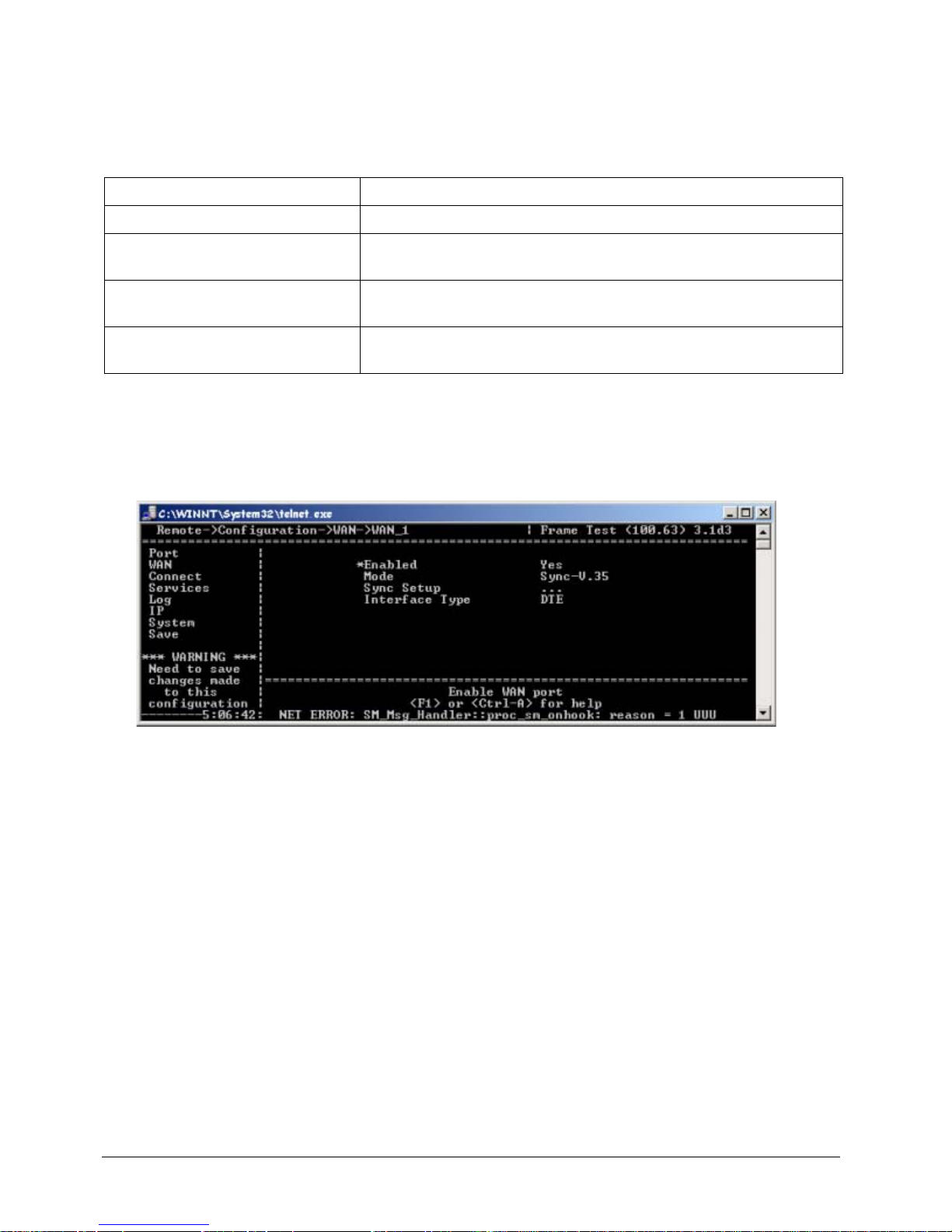
1. Access the WAN 1 or WAN 2 Menu using the following path:
MI Path
Configuration->WAN->WAN_1 (or 2)
2. The following menu appears. Press the → key to access the Enabled parameter.
Figure 3-8: Enabling WAN 1 or 2
3. Press the → key to change the availability of the port to: Enabled (Yes) or Disabled (No).
4. Press the ← key to accept changes and go back to the Configuration Menu.
5. Press the ↓ key to the Save parameter .
6. Press Enter to save changes to the active config (.rem) file.
Setting Description
Enabling/Disabling WAN ports Individually Enable or Disable a specific WAN port (see below).
Setting the Sync Rate Sets the specific WAN port to the sync rate (synchronous serial port
transfer speed) of the network device (CSU/DSU).
Setting the Mode (signalling protocol)
Choose the interface signaling type used to communicate with the
network device.
Choosing the Interface Type The interface type for the EXTender 7000 is DTE (Data Terminal
Equipment).
Page 32
EXTender
TM
7000 Installation Guide Page 32
Setting the Sync Rate
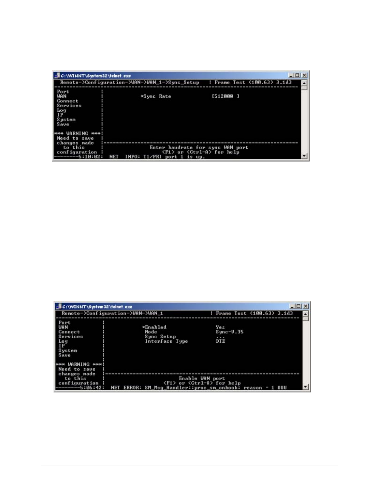
1. Access the WAN 1 or WAN 2 Sync_Setup Menu using the following path:
MI Path
Configuration->WAN 1 or 2->Sync_Setup
The following menu appears.
Figure 3-9: Sync Rate
2. Press the → key to the Sync Rate parameter and type in the correct Sync rate. This parameter sets the
synchronous data transfer speed of the WAN por t and must match the network device speed.
Note: This Sync Rate information, displayed in bytes, must be obtained through the network device documentation.
3. Press the ← key to accept chan ge s an d go back to th e Con fig u ra tio n Me n u.
4. Press the ↓ key to the Save parameter.
5. Press Enter to save changes to the active config (.rem) file.
Setting the Mode (Signaling Protocol)
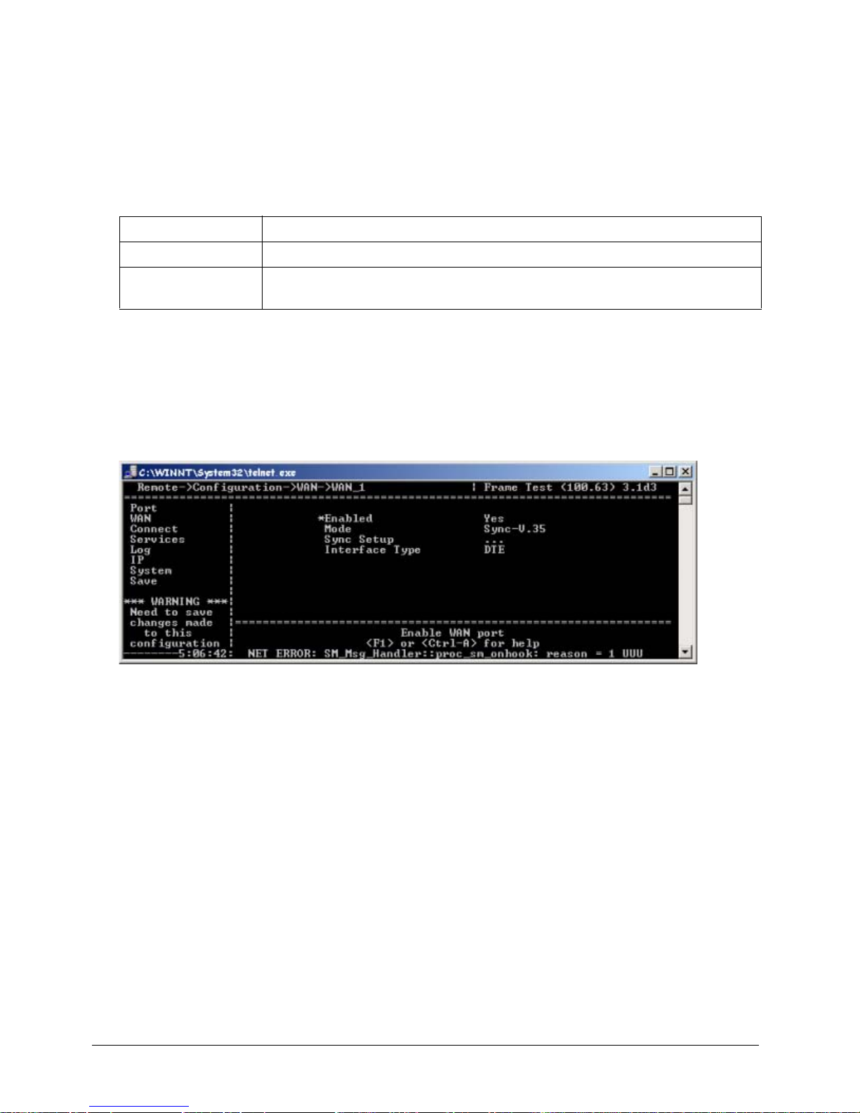
1. Access the WAN 1 or WAN 2 Menu using the following path:
MI Path
Configuration->WAN 1 or 2
2. The WAN menu appear s. Press the → key to access the parameters.
Figure 3-10: Setting Mode for WAN 1 or 2
3. Press the ↓ key to the Mode parameter. This parameter mu st match the protocol used by the network
device connected to the WAN port. Press the → key to scroll through the available protocols.
4. Press the ← key to accept chan ge s an d go back to th e Con fig u ra tio n Me n u.
5. Press the ↓ key to the Save parameter.
6. Press Enter to save changes to the active config (.rem) file.
Page 33
EXTender
TM
7000 Installation Guide Page 33
Setting the Interface Type
1. Access the WAN 1 or WAN 2 Menu using the following path:
MI Path
Configuration->WAN 1 or 2
2. The WAN menu appears. Press the → key to access the parameters.
3. Press the ↓ key to the Interface Type parameter, which has the following values:
Notes:
DTE is typically used to connect to a third party CSU/DSU for RVP_Direct (Serial RVP) installations.
DCE is typically used in Add/Drop configurations (connecting to an EXTender 6000 or a Router). In DCE
installations, you must use the 25 pin Female- to -F emale crossover cable (DB-25, RS-530) that we provide.
4. For most connections, you will want to set the this parameter to DTE.
Figure 3-11: Interface Type
5. Press the ← key to accept changes and go back to the Configuration Menu.
6. Press the ↓ key to the Save parameter .
7. Press Enter to save changes to the active config (.rem) file.
Value Description
DCE The WAN port on the EXTender 7000 connects to a DTE device.
DTE The WAN port on the EXTender 7000 PBXgateway II connects to a DCE
device.
Page 34
EXTender
TM
7000 Installation Guide Page 34
RVP_Direct via PRI Configuration
This section describes configuring the EXTender 7000 for a basic RVP Direct via PRI installation using the
T1/PRI ports on the MCK T1/PRI Card.
Figure 3-12: Shared PRI Configuration
Installation
• Connect a PRI line from the network to the Network Interface card (MCK T1/PRI Card) on the port
labeled Port 1 of the EXTender 7000.
• Connect a PRI line from the network to the Network Interface card (MCK T1/PRI Card) on the port
labeled Port 1 of the PBXgateway II.
Prerequisites for Configuration
• The PBXgateway II (at the corporate site) and the EXTender 7000 (at the branch office) must be physically installed properly and the network link between both devices must be installed and provisioned to
meet the “Network Requirements” defined in this document.
• The T1/PRI Port (WAN 3) setup parameters for the PBXgateway II must be set to match the corresponding parameters on the EXTender 7000.
Required Configurable Parameters
• RVP_Direct Parameters - Please see “RVP_Direct Parameters - PRI on page’ 35.
• T1/PRI (WAN3) - Please see “T1/PRI (WAN3) Settings - PRI on page’ 35.
• Set T1/PRI Service Parameters - Please see “Set the T1/PRI Service Parameters on page’ 37.
• Channel Setup - Please see “Channel Setup - PRI on page’ 36.
• Local Dialing - Please see “Local Dialing Via PRI on page’ 66.
Branch Office
Standard Telephone
PSTN
Corporate Office
PBX
Local CO Line
(T1/PRI)
PBXgateway II
EXTender 7000
T1/PRI Card
T1/PRI Card
Digital Port
City B
City A
PBX Telephone
7000 Telephones
Page 35
EXTender
TM
7000 Installation Guide Page 35
RVP_Direct Parameters - PRI
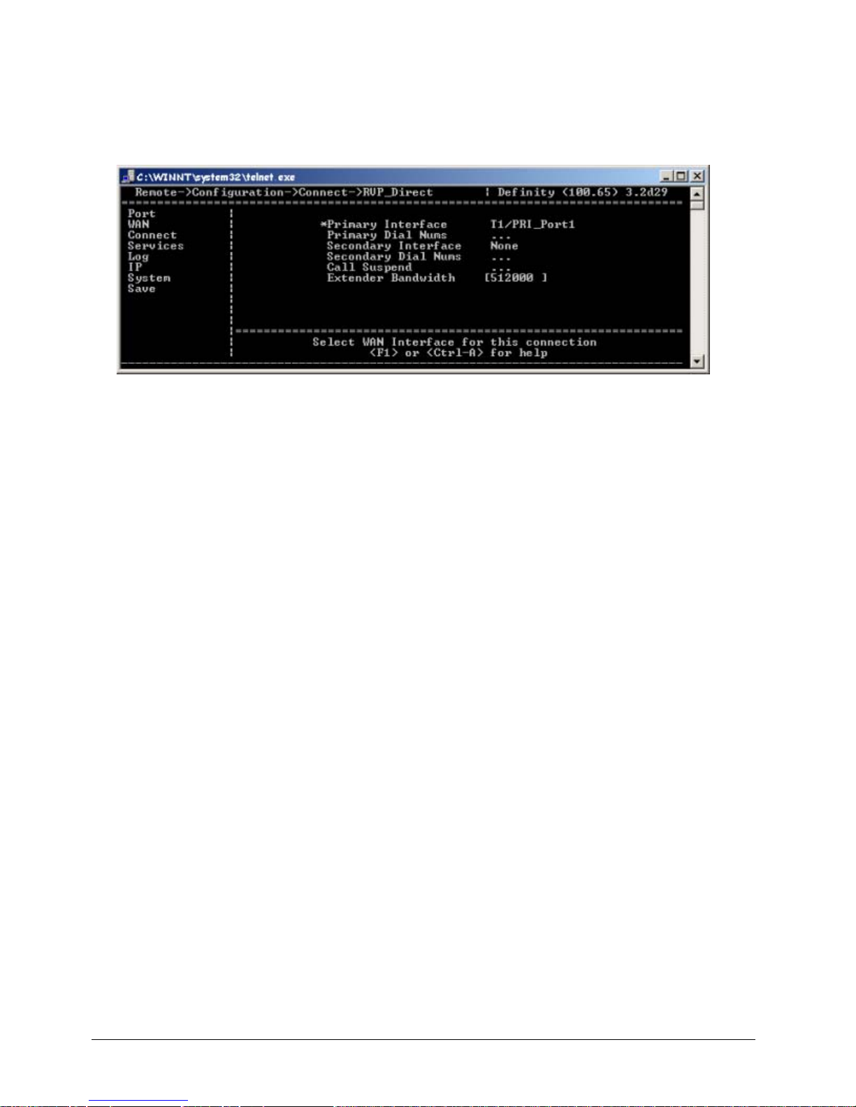
1. Access the RVP_Direct Menu using the following path:
MI Path
Configuration->Connect->RVP_Direct
The following menu appears:
Figure 3-13:
2. Set the Primary Interface parameter to T1/PRI_Port1.
3. Set the Extender Bandwidth parameter to the total bandwidth that will be required by the extended
telephones. Bandwidth required by an RVP Direct over PRI system is determined by the type of PBX
used, the com-pression algorithm, and number of extended phones that will need to be off-hook at the
same time. Use the MCK Bandwidth Calculator to compute the value of the EXTender BW parameter.
This calculator is located on your documentation CD and can be downloaded from our website:
www.MCK.com. Note: Dif ferent bandwid th requirement s exist for different EXTender 7000/PBXgateway
II configurations.
4. Press the ← key to accept changes and go back to the Configuration Menu.
5. Press the ↓ key to the Save parameter.
T1/PRI (WAN3) Settings - PRI
This section provides instruction for the configuration of the Leased TI line that is connecting the EXTender
7000 to the Gateway.
1. Go to the T1/PRI Port Setup Menu to perform the basic setup for the T1/PRI ports and channels. This
menu is located in the WAN submenu structure, and can be accessed using the following path:
MI Path
Configuration->WAN->T1/PRI_Port(WAN3)->T1/PRI_Port_1
Page 36
EXTender
TM
7000 Installation Guide Page 36
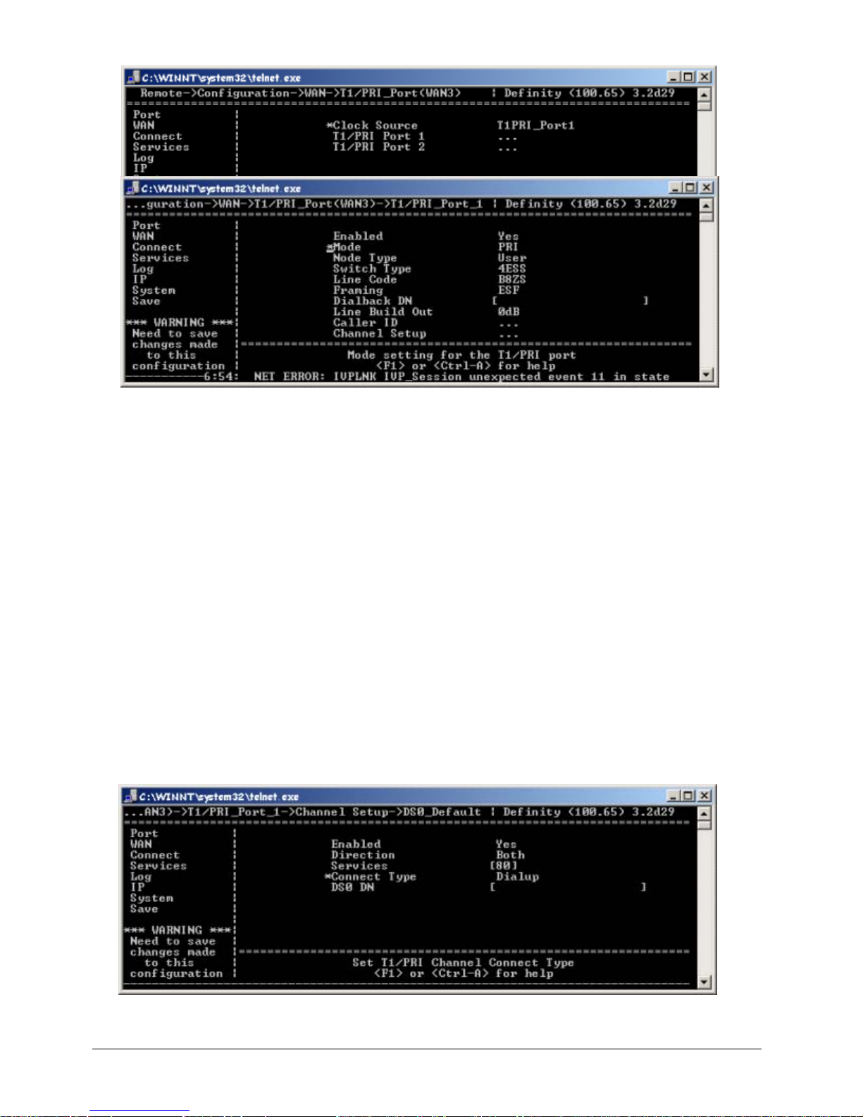
The following menu appears:
Figure 3-14: T1/PRI Port (WAN3) Parameters
2. Set the Clock Source parameter to T1PRI_Port1.
3. Set the Enabled parameter to Yes.
4. Set to Port 1 if the network is providing timing, or Port 2 to use the EXTender 7000 for the timing source.
Note: Point-to -Point T1’s DO NOT provide timing.
5. Set the Mode parameter to PRI.
6. The Switch Type, Line Code and Framing parameters to be provided by the Telco.
7. The PBXgateway II uses the Dialback DN parameter to connect to the EXTender 7000. Enter a phone
number of the PRI line that is connected to the EXTender 7000.
8. Set the Line Code and Framing parameters with values provided by the Telco company (CO).
9. Select a value for the Line Build Out parameter to attenuate the signal before it leaves the extender.
Use a value recommended by the Telco company (CO).
Channel Setup - PRI
Assigning DS0 Channels
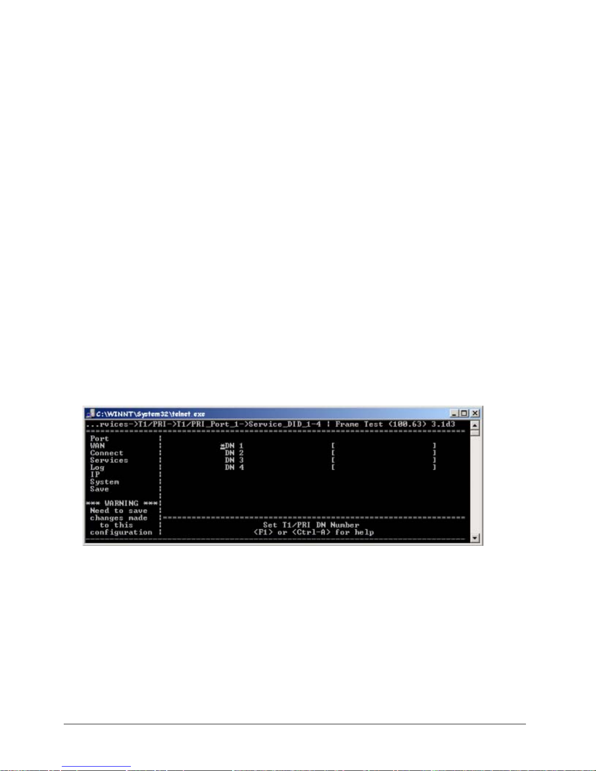
1. Use the arrow keys to access the DS0_Default Channel Setup menu, as shown below:
MI Path
Configuration->WAN->T1/PRI_Port(WAN3)->T1/PRI_Port_1-> Channel Setup-
>DS0_Default
Figure 3-15: Assigning DS0 Channels
Page 37
EXTender
TM
7000 Installation Guide Page 37
2. Set the Enable parameter to Yes.
3. Set Direction to Both.
4. Enter 80 into the Services parameter. This parameter enables you to select the services you wish to
use to connect to the Central Office (CO). The value of 80 assigns Dialup Service to all DS0 channels.
5. Set the Connect Type to Dialup.
Entering Primary Dial Numbers
MI Path
Configuration->Connect->RVP_Direct->Primary Dial Nums
1. Press the arrow keys to access the Primary Dial Num 1 parameter. Ente r the phone number associated with the T1/PRI circuit connected to the PBXgateway II.
2. Press the ← key to accept changes and go back to the Configuration Menu.
3. Press the ↓ key to the Save parameter .
4. Press Enter to save changes to the active config (.rem) file.The EXT ender 7000 is now ready to connect
to a PBXgateway II and extend up to 24 digital telephones.
Note: This configuration does not support Local Dialing. To expand this configuration to support Local
Dialing, see “Local Dialing Configurations on page’ 66 for detailed instructions.
Set the T1/PRI Service Parameters
After you have set the RVP_Direct parameters, continue with the steps below. Access the T1/PRI Service
parameters to specify the Dialback number.
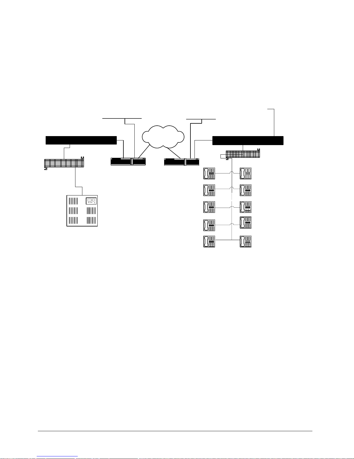
1. Access the DN menu (for the first 4 possible numbers) using the following path:
MI Path
Configuration->Services->T1/PRI->T1/PRI_Port_1->Service_DID_1-4
The following menu appears:
Figure 3-16: Shared PRI T1/PRI Service Parameters
2. Enter a single DN number in the DN 1 parameter. This is the DID number of the EXTender 7000. This
value is provided by the Telco company (CO).
Page 38
EXTender
TM
7000 Installation Guide Page 38
RVP Over IP Configuration
The following pages provide step-by-step instructions for configuring a basic RVP_over _IP installation using
the LAN port on the EXTender 7000. To configure the system, you will set various parameters in the Management Interface (MI).
Note: This configuration does not support Local Dialing. To expand this configuration to support Local Dialing, see “Local Dialing Configurations on page’ 66 for detailed instructions.
After installation, the system should be connected as shown in the figure below:
Figure 3-17: RVP Over IP Installation
Prerequisites for Configuration
• The PBXgateway II (at the corporate site) and the EXTender 7000 (at the branch office) must be physically installed properly and the network link between both devices must be installed and provisioned to
meet the “Network Requirements” defined in this document.
• The network administrator must allocate an IP address for both units.
TCP/UDP Requirements
Ensure that the correct TCP/UDP ports have been opened to allow the EXTender to connect to the PBXgateway II through your company firewall. The following TCP/UDP port requirements must be met:
for Extending Digital Telephones
• The remote unit uses UDP ports 12288 to 12544 to extend the telephones. The port numbers start at
12288 and increment by 2 to the total number of ports used. For example if you have a 24 port
EXTender 7000 with three phones connected, then ports 12288, 12290, and 12292 would need to be
opened.
To ensure access to these ports, you should open all the ports in the range (ports 12288 to 12544).
• The PBXgateway II unit uses port 2698 TCP/UDP.
IP Network
Branch Office
Punch Block
Analog Phone Line
EXTender 7000
Punch Block
PBX
Corporate Office
PBXgateway II
Router
Router
LAN LAN
Page 39
EXTender
TM
7000 Installation Guide Page 39
for Local Dialing
• To support Local Dialing, the EXTender 7000 unit uses UDP ports 16384 to 16640. The port numbers
start at 16384 and increment by 1 to the total number of ports used. For example, if 3 telephones need
to make local calls, then ports 16384, 16385, and 16386 would need to be opened.
To ensure access to these ports, you should open all the ports in the range (ports 16384 to 16640).
• The PBXgateway II unit uses port 2698 TCP/UDP.
RVP_IP - Configuration
Connect Parameters - RVP_Over_IP
The EXTender 7000 utilizes a LAN connection to provide remote user connectivity. This means that the LAN
port is plugged into an IP network and is assigned an IP address. The LAN port labeled AUX LAN is used
for remote administration purposes only (i.e. a Telnet session). The IP Destination (the IP address of the
PBXgateway II) must be entered within the MI of the EXTender.
Procedure
1. Access the Connect menu using the following path :
MI Path
Configuration->Connect
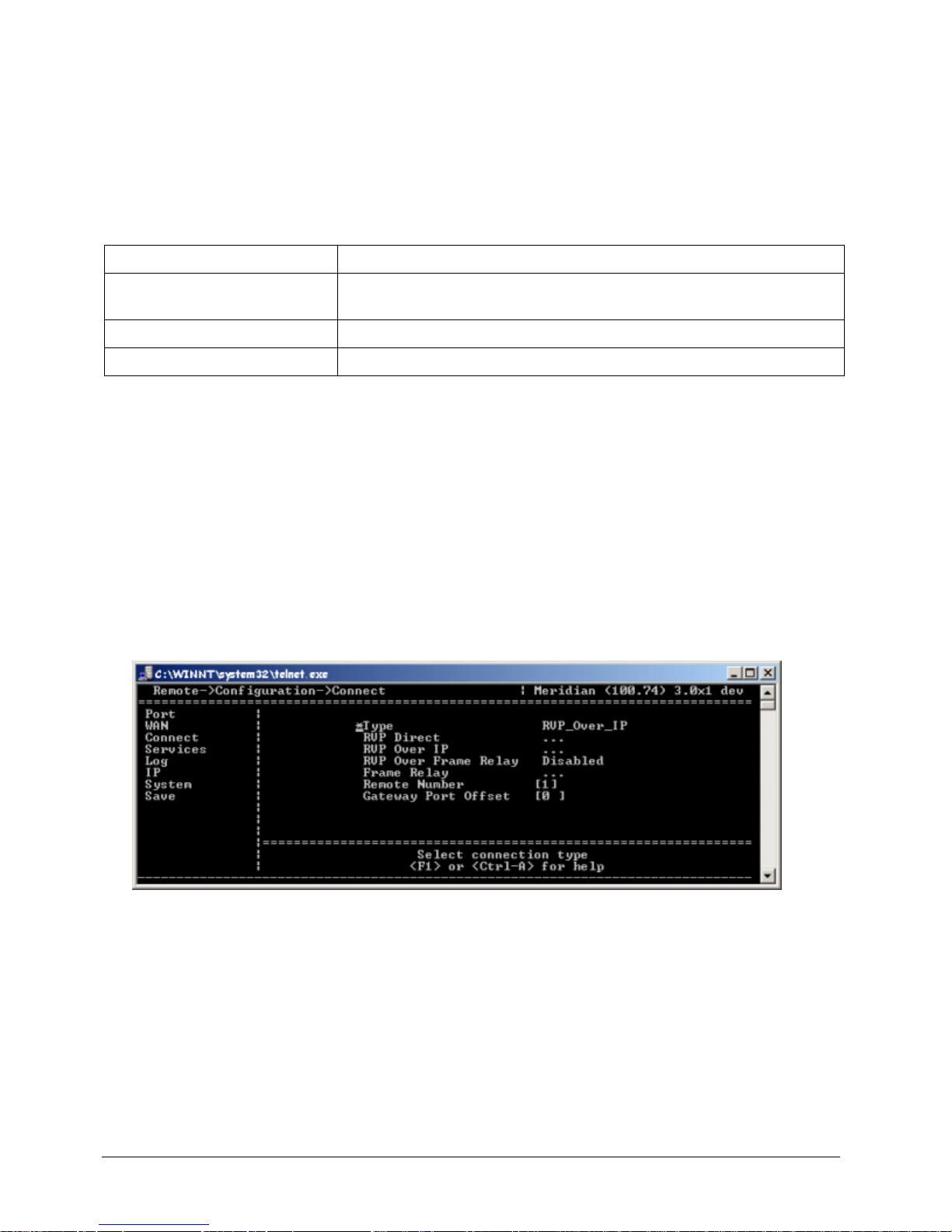
2. If necessary, use the → key to access the Type parameter. Set this parameter to RVP_Over_IP.
Figure 3-18: Connect Menu
3. Use the arrow keys to access the RVP_Over_IP submenu.
MI Path
Configuration->Connect->RVP_Over_IP
You Have to... In order to...
Set the IP Parameters. Allow the EXTender 7000 to communicate with the PBXgateway II over
an IP network.
Disable both WAN ports. Disable ports that are not used for RV P_over_IP.
Configure the EXTender 7000. Set the required IP and Connect parameters.
Page 40
EXTender
TM
7000 Installation Guide Page 40
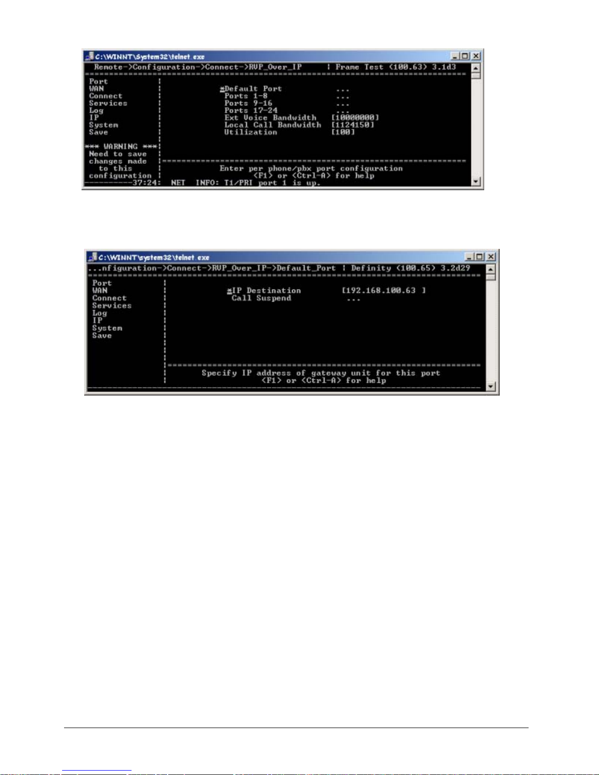
The following menu appears:
Figure 3-19: RVP_Over_IP Menu
4. Use the arrow keys to access the Default Port menu.
MI Path
Configuration->Connect->RVP_Over_IP->Default_Port
Figure 3-20: RVP_Over_IP Default Port Menu
5. In the IP Destination field enter the IP address of the PBXgateway II provided by the network administrator. This will be the IP Destination for all 24 phone ports.
Note:
The IP address must be assigned by the network administrator . Setting the IP Destination parameter in
the Default Port menu connects all the ports on the EXTender to the same Gateway unit. You can
assign ports to different Gateway units by accessing the specific Port menu (for example, Port_4), then
entering the IP address of the Gateway in that menu.
6. Use the arrow keys to enter the IP Destination addresses on a per port basis if required.
7. The Ext Voice Bandwidth parameter is used to specify the Bits Per Second to use for voice. It is recommended this setting be left at the default value of 10000000.
8. The Local Call Bandwidth parameter is used to configure the maximum number of users for simultaneous non-Hairpinned calls. The maximum setting, also the default, is 1124150 and allows for 10 non-
Hairpinned calls.
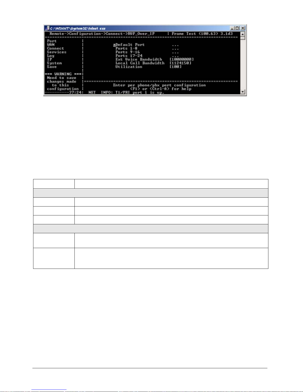
9. The Utilization parameter is used to set the percent age of the bandwid th to be used. It is recommended
Page 41
EXTender
TM
7000 Installation Guide Page 41
that this setting be left at 100.
Figure 3-21: RVP_Over_IP
10. Press the ← key to accept the changes and go back to the Configura tio n me n u.
11. Press the ↓ key to navigate to the Save parameter.
IP Parameters
An Internet Protocol (IP) address and associated routing parameters must be entered within the IP menu of
the EXTender for identification purposes within the LAN (Local Area Network).
Note: The IP address (as well as any required mask or router addresses) must be provided by the network
administrator.
Setting the Network IP Addresses
1. Access the IP Address Menu using the following path:
MI Path
Configuration->IP->LAN->Address
Setting Description
The following IP settings are required:
Address This is the IP address of the EXTender.
Subnet Mask A number used to identify the IP subnetwork on the LAN.
Default Router The address of a device used to reach IP hosts not on this IP subnetwork.
The following IP settings are option al:
Telnet This parameter must be Enabled to allow access to the Management Interface via a
Telnet session.
Web Server This parameter must be Enabled to allow access to the Management Interface via a
web browser (Microsoft Internet Explorer 5.x or higher, or Netscape Communicator
4.7x or higher).
Page 42
EXTender
TM
7000 Installation Guide Page 42
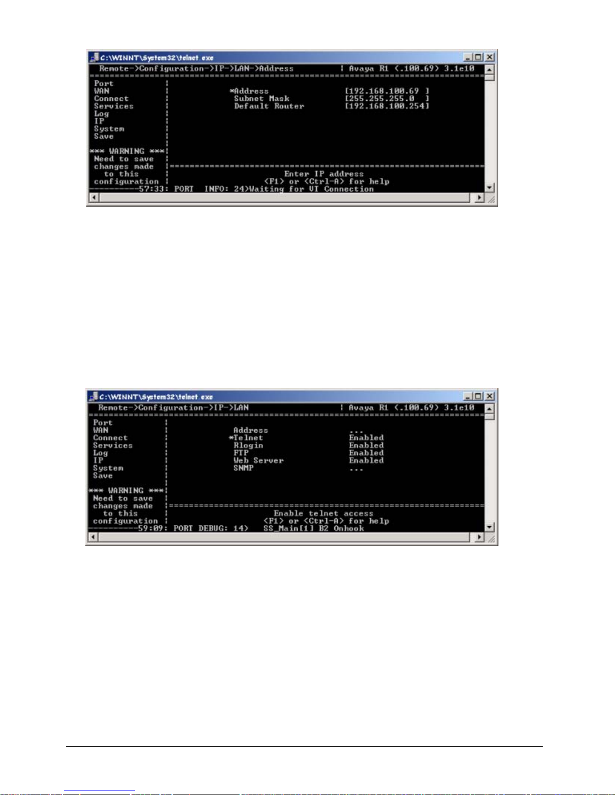
The following menu appears:
Figure 3-22: IP Address Menu
2. Press the → key to access the parameters.
3. Press the → key to the Address parameter. Enter the IP Address of the EXTender and press Enter.
4. Press the ↓ key to the Subnet Mask parameter. Enter the IP Address of the Subnet Mask and press
Enter.
5. Press the ↓ key to the Default Router parameter. Enter the IP Address of the Default Router and pr ess
Enter.
6. If you want to enable Telnet access, press the ← key to access the IP Menu.
7. Press the ↓ key to the Telnet parameter. If necessary, press the → key to set the parameter to Enabled.
8. If you want to enable web browser access, press the ↓ key to the Web Server parameter. If necessary,
press the → key to set the parameter to Enabled.
Figure 3-23: Enabling the LAN
9. Press the ← key to accept chan ge s an d re tu rn to the C on fig ur at ion Me nu.
10. Press the ↓ key to the Save option.
11. Press Enter to save changes to the active config (.rem) file.
Page 43
EXTender
TM
7000 Installation Guide Page 43
RVP_Over_Frame Relay Configuration
This section provides the necessary information to configure the EXTender 7000 for connection within a
Frame Relay network using the MCK WAN card. Note: To prevent Quality of Service (QoS) issues, you
must use separate PVCs for voice and data traffic.
Note: This configuration does not support Local Dialing. To expand this configuration to support Local Dialing, see “Local Dialing Configurations on page’ 66 for detailed instructions.
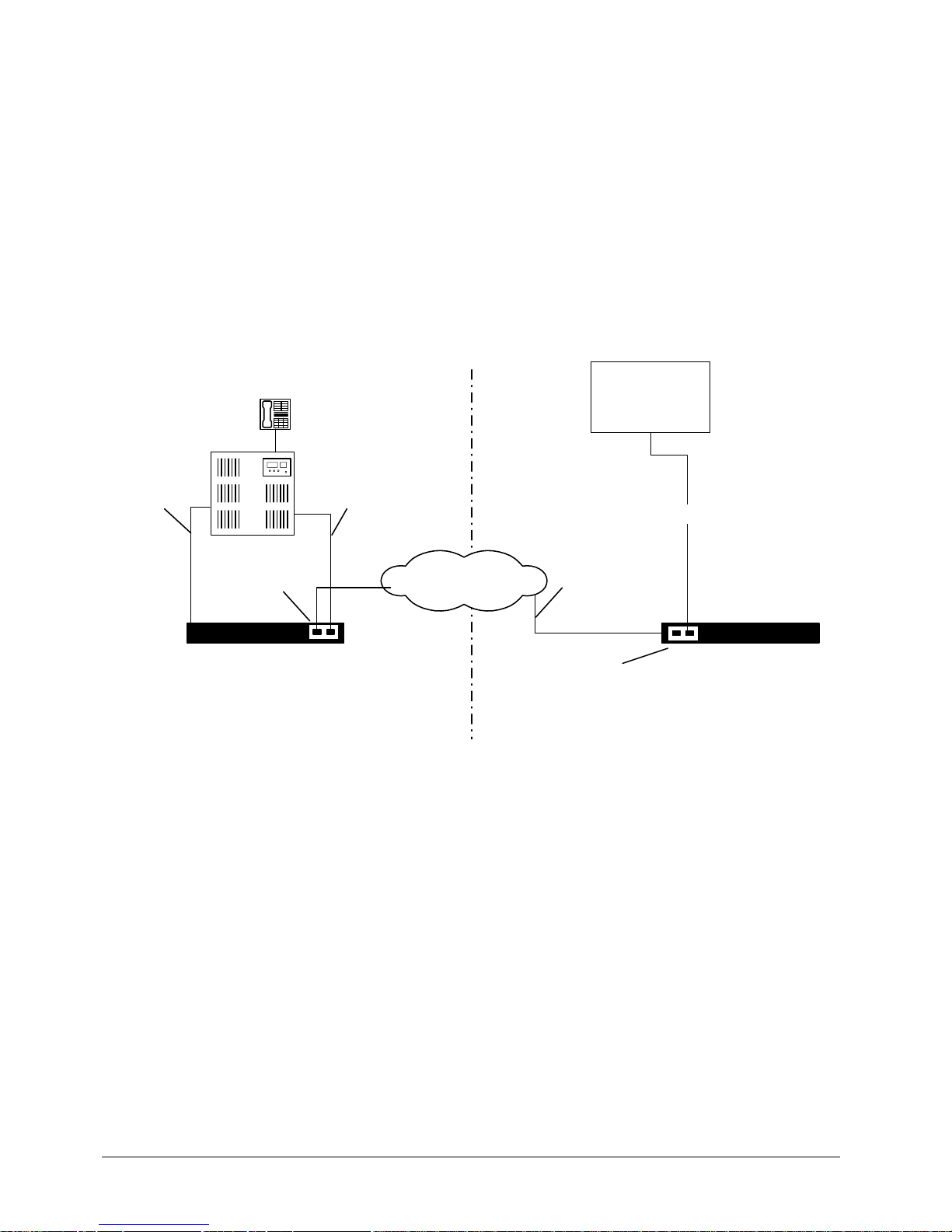
In the diagram below, the router is connected to a WAN port on the EXTender 7000, and the Frame Relay
network is connected to the MCK T1/PRI card. The MCK T1/PRI card acts as a Frame Relay Access Device
(FRAD).
Figure 3-24: Frame Relay Installation
Prerequisites for Configuration
• The PBXgateway II (at the corporate site) and the EXTender (at the branch office) must be installed
properly.
• The Frame Relay PVCs are provisioned by your service provider. You will need one PVC for the
extender link (voice) and an additional PVC for each dat a connection.
• DLCI numbers for each PVC and LMI type used for the Frame Relay connection.
• Get the values for the Switch Type, Line Code, and Framing parameters from your service provider
(Telco).
Branch Office
Frame Relay
Corporate Offi ce
PBX
Channelized T1
to Frame Relay
PBXgateway II
EXTender 7000
T1/PRI Card
Digital P o rt
City B
City A
Digital Trunk Live
(PRI)
MCK T1/PRI
Card
Central Office
T1/PRI
Page 44
EXTender
TM
7000 Installation Guide Page 44
Frame Relay Connect Parameters
Setting the Interface Parameters
1. Access the Connect menu.
MI Path
Configuration->Connect
2. Set the Type parameter to RVP_Direct.
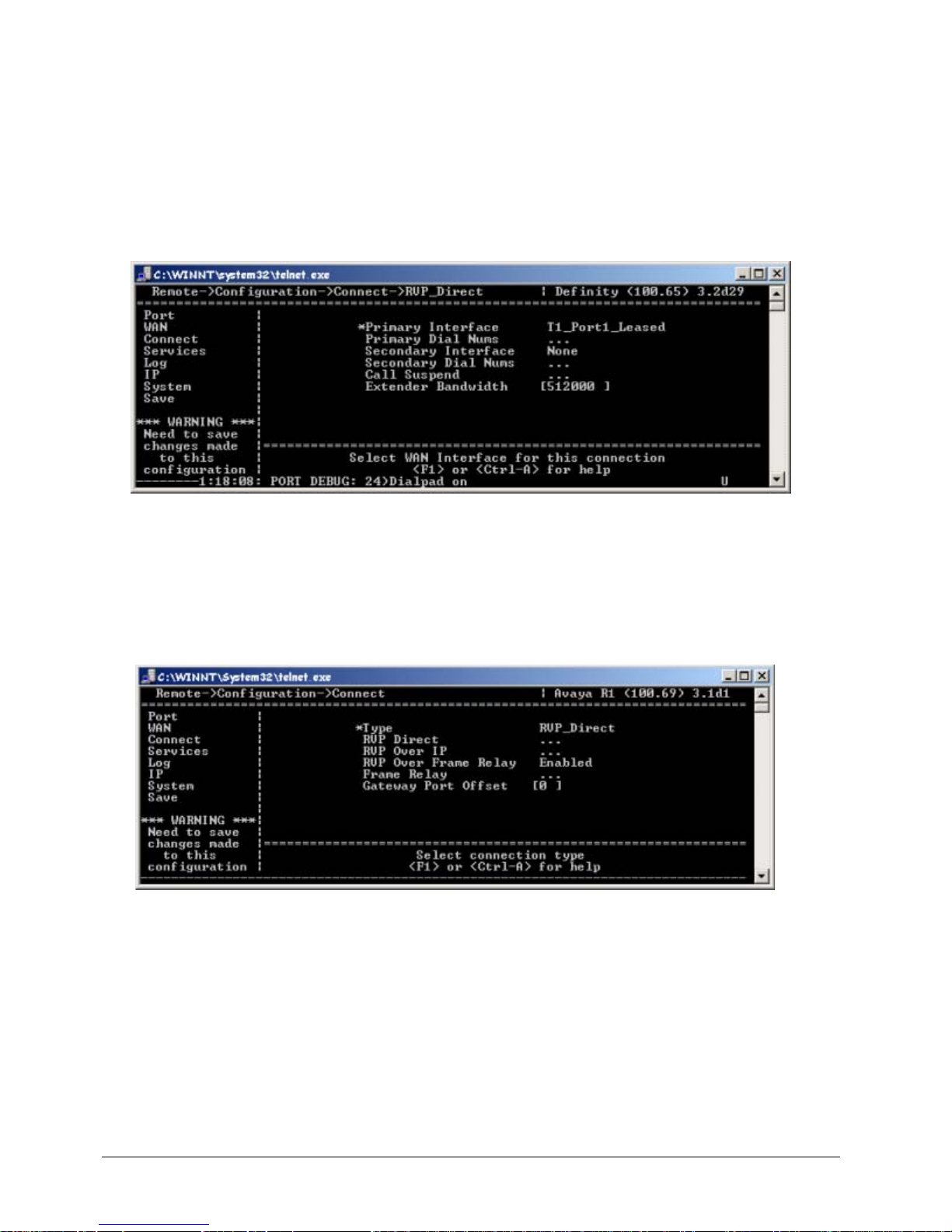
3. Use the arrow keys to access the Primary Interface parameter. Set this parameter to
T1_Port1_Leased.
Figure 3-25: Primary Interface
4. Set the Extender Bandwidth parameter to the total bandwidth that will be required by the extended
telephones. Bandwidth required by an RVP Direct over T1 system is determined by the type of PBX
used, the compression algorithm, and number of extended phones that will need to be off-hook at the
same time. Use the MCK Bandwidth Calculator to compute the value of the EXTender BW parameter.
This calculator is located on your documentation CD and can be downloaded from our website:
www.MCK.com.
5. Set RVP Over Frame Relay to Enable.
Figure 3-26: Connect Type - RVP_Direct
6. Access the Frame Relay menu by using the following path.
Page 45
EXTender
TM
7000 Installation Guide Page 45
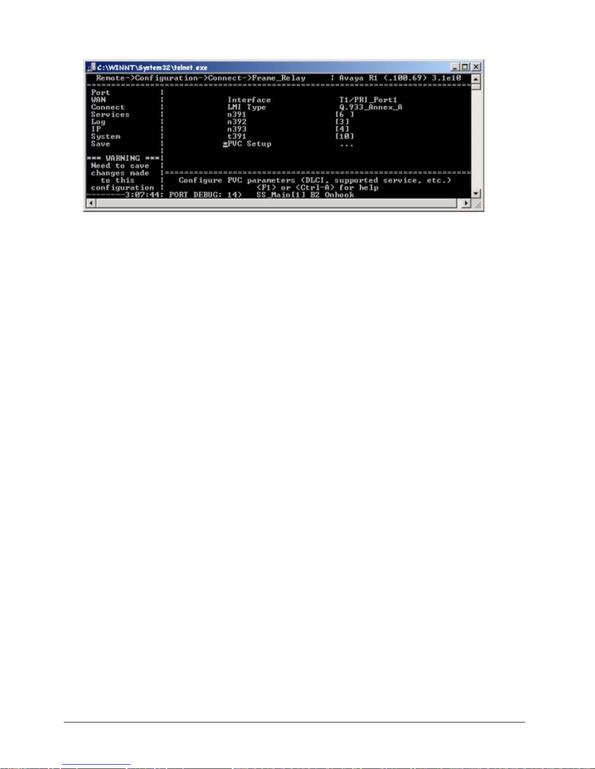
MI Path
Configuration->Connect->Frame Relay
Figure 3-27: Frame Relay Menu
7. Set the Interface parameter to T1/PRI_Port 1 to identify the Frame Relay interface on the EXTender
7000. Note, we are limited to using only T1 Port 1 for Frame Relay.
Note: There can only be one network interfa ce when usin g frame re lay, meaning there is no Primary or
Secondary interface.
8. Set the LMI Type parameter to Q.933_Annex_A or ANSI_ Annex_ D as specified by your service pro-
vider.
Page 46
EXTender
TM
7000 Installation Guide Page 46
9. Set the following parameters specified by your service provider . If not, leave these values at the default
setting:
Table 4: LMI T1 Parameters
10. Set the PVC parameters.
Setting the Frame Relay PVC Parameters
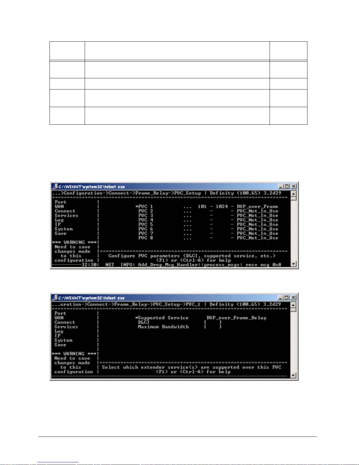
1. Use the arrow keys to access the following PVC_Setup menu.
MI Path
Configuration->Connect->T1/Frame_Relay->PVC Setup
Figure 3-28: T1/PVC Setup Menu
2. Press the → key to access the PVC parameters screen.
Figure 3-29: PVC_1
3. Set the Voice PVC Supported Service parameter for the EXTender link to RVP_over_Frame_Relay.
4. Set the DLCI (Data Link Connection Identifier) for this PVC (16 - 1007). This number is given to you by
your service provider. The DLCI field defaults to blank and is cleared automatically if you set the PVC
type to "Not In Use."
Field Definition Default
Value
n391
Full Status Polling Cycles - the number of status inquiries between
each full status report.
6
n392
Error Threshold number
3
n393
Monitored Events Count - the number of status messages that are
tracked to determine if more than n392 errors have been detected.
4
t391
Link Integrity V erification Timer - Time to wait between sending each
status inquiry message.
10
Page 47
EXTender
TM
7000 Installation Guide Page 47
5. Set the Maximum Bandwidth to the specified amount of guaranteed bandwidth (measured in bits per
second) on a Frame Relay service. Use MCK’s Bandwidth calculator.
6. Repeat steps 3 -5 for each additional PVC (ie. Add/Drop PVC(s)).
7. Use the ← and ↓ keys to return to the Save option.
8. Press Enter to save changes to the active config (.rem) file.
T1/PRI Port (WAN3) Frame Relay Parameters
This section provides instruction for the configuration of the Leased TI line that is connecting the EXTender
7000 to the Gateway.
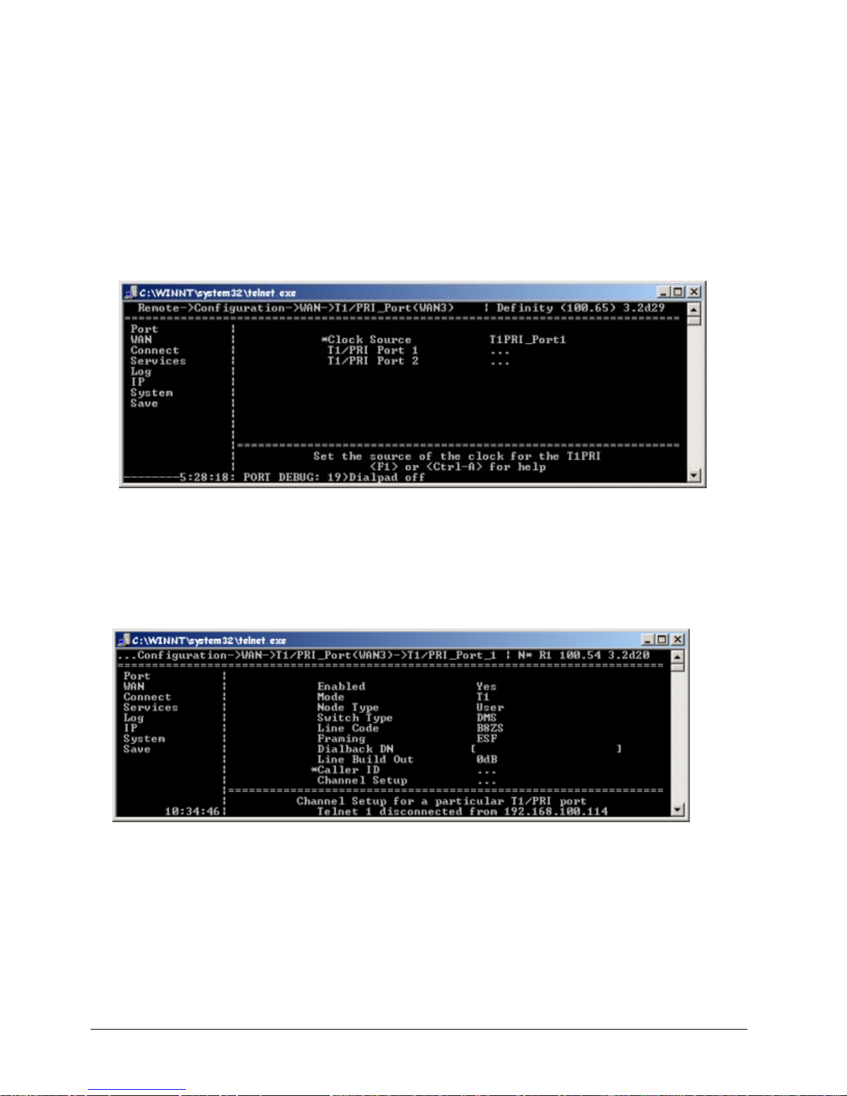
1. Set the Clock Source parameter to T1PRI_Port1.
• Set to Port 1 if the network is providing timing, or Port 2 to use the EXTender 7000 for the timing
source. Note: Point-to -Point (RVP_Direct) T1’s DO NOT provide timing.
Figure 3-30: Clock Source
2. Go to the T1/PRI Port Setup Menu to perform the basic setup for the T1/PRI ports and channels. This
menu is located in the WAN submenu structure, and can be accessed using the following path:
MI Path
Configuration->WAN->T1/PRI_Port(WAN3)->T1/PRI_Port_1
The following menu appears:
Figure 3-31: T1/PRI Port (WAN3) Parameters
3. Set the Enabled parameter to Yes.
4. Set the Mode parameter to T1.
5. Ignore the following parameters, as they do not apply to Leased T1 configurations: Node Type, Switch
Type, and Dialback DN.
6. Set the Line Code and Framing parameters with values provided by the Telco company (CO).
7. Select a value for the Line Build Out parameter to attenuate the signal before it leaves the extender.
Use a value recommended by the Telco company (CO).
Page 48
EXTender
TM
7000 Installation Guide Page 48
Dedicated Service to the DS0 Channel
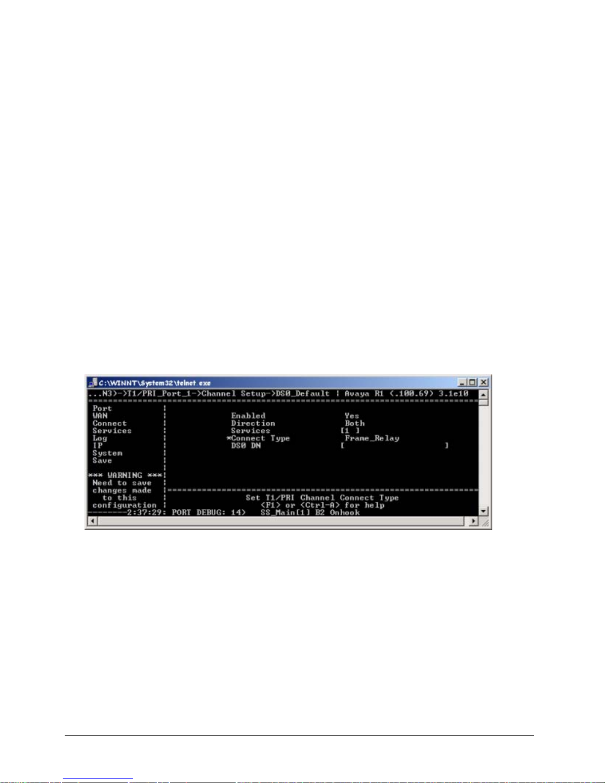
You may set some or all of the 24 channels to use Frame Relay. Note though, that only setting the default
will cause all channels to be used for Frame Relay. If any DS0 channels have been configured for Add/Drop
(using RVPoIP for example), they will be ignored and the Add/Drop configured PVCs will be used instead.
The number of DS0 channels used to carry Frame Relay is p art of the service agreem ent, worked out by the
customer and the telco. The number of DS0 channels set for Fr ame Rela y he re ne eds to match the n umber
of DS0 channels that are being used by the telco.
DSO Channel Assignment Options
If you wish to use all 24 channels set the default menu to Frame Relay and set all of the individual DS0
channel menus to use <default>.
If you wish to use less than 24 channels, assign a subset of DS0 channels using one of the following methods:
• Set the default to Frame Relay and then assign all non-Frame Relay DS0 channels to something else,
such as dialup;
• Set the default to something other than Frame Relay, then manually set each DS0 channel menu to use
Frame Relay. If there are more than 12 Frame Relay DS0 channels then it is easier to use the first statedmethod.
Assigning DS0 Channels
1. Use the arrow keys to access the DS0_Default Channel Setup menu, as shown below:
MI Path
Configuration->WAN->T1/PRI_Port(WAN3)->T1/PRI_Port_1-> Channel Setup-
>DS0_Default
Figure 3-32: Frame Relay - Assigning DS0 Channels
2. Set the Enable parameter to Yes.
3. Enter 1 into the Services parameter . This p arameter enables you to select the services yo u wish to use
to connect to the Central Office (CO). The value of 1 assigns a Dedicated T1 Service to all DS0 channels.
4. Set the Connect Type to Frame_Relay.
Page 49
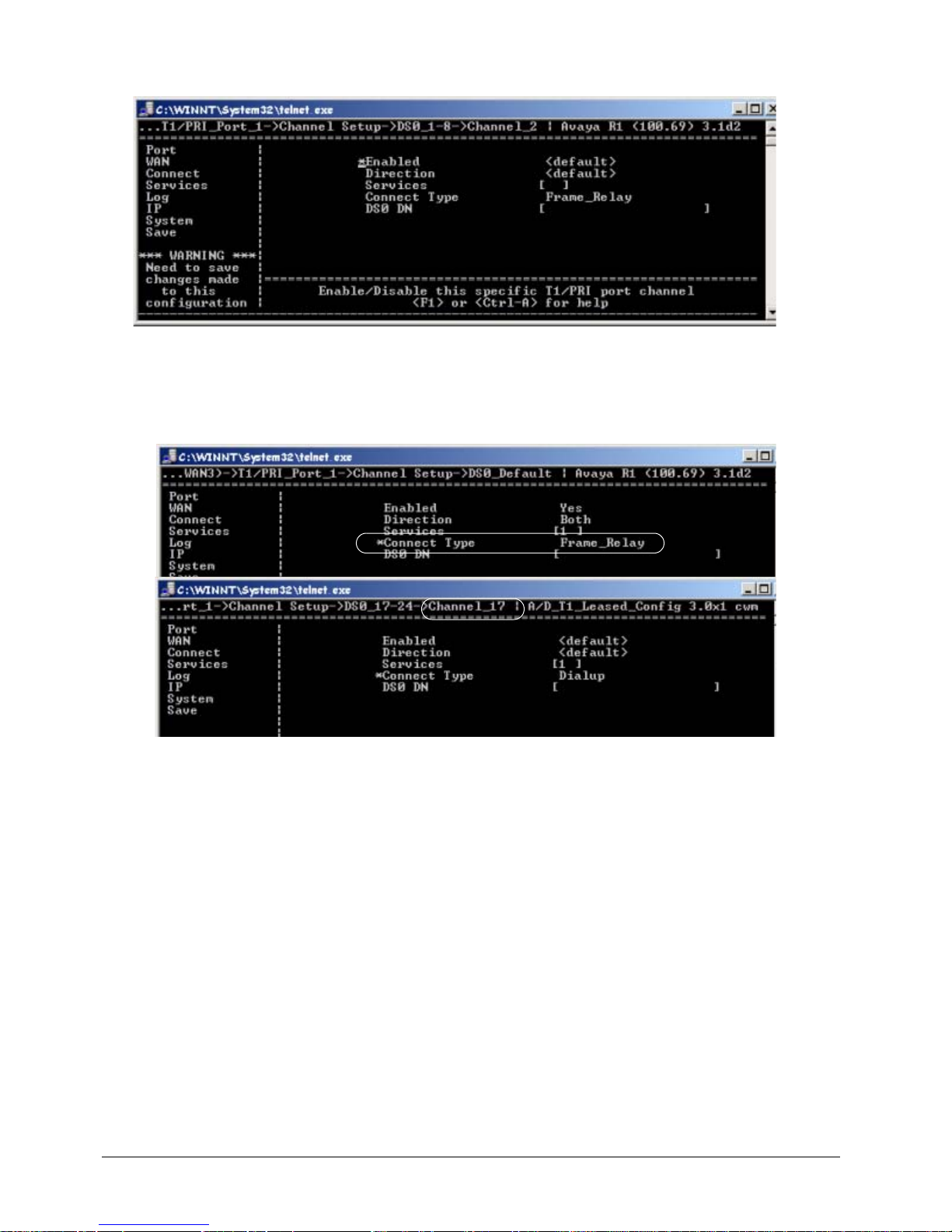
EXTender
TM
7000 Installation Guide Page 49
5. (All channels in use) If all 24 channels are used, set the default menu to Frame Relay and set all of the
individual DS0 channel menus to use <default>.
Figure 3-33: Frame Relay - All Channels in Use
6. (Less than 24 channels) If less than 24 channels are being used assign a subset of DS0 channels by
either:
• Set the default to Frame Relay and then assign all non-Frame Relay DS0 channels to something
else, such as dialup
Figure 3-34: Frame Relay - Less than 24 Channels in Use
or
• Set the default to something other than Frame Relay and then manually set each DS0 channel
menu to use Frame Relay. Use the channels with higher numbers (17-24) as Frame Relay channel
assignment occurs sequentially (from the lowest to the highest). This will help eliminate assigning a
channel that has already been used.
Verifying Frame Relay Parameters
To verify the Frame Relay parameters are correct monitor the Frame Relay status screen to see if LMI p ackets are being exchanged with the Frame Relay network. Once enough packets are exchanged the status
screen will change to indicate that the network connection is UP.
Procedure
1. Use the arrow keys to access the Frame Relay Status menu, as shown below:
Note: The Frame Rrelay stats are for the Voice PVC only.
MI Path
Status->Connect->Frame Relay
Page 50
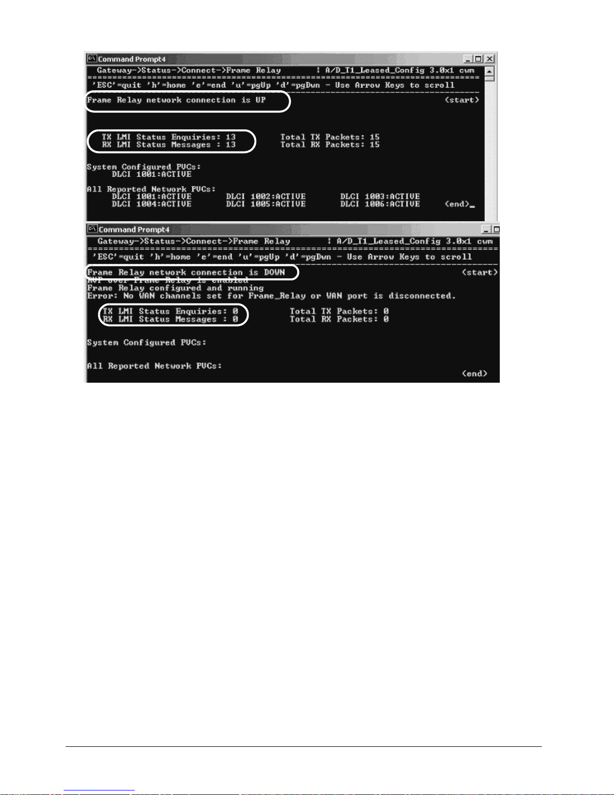
EXTender
TM
7000 Installation Guide Page 50
The following screen appears:
Figure 3-35: Verifying Frame Relay Connections
2. Verify that the Frame Relay connection is UP. Status Inquires are sent every 10 secs.
Page 51

EXTender
TM
7000 Installation Guide Page 51
Chapter 4: Applications
The following chapter will provide you with information and instruction on configuring applications such as
Add/Drop, 2:1 Configuration and Local Dialing on your EXTender 7000.
For more detailed information on the applications contained within this chapter please see the EXTender
7000 User’s Guide and the PBXgateway II System Administrator’s Guide.
Page 52
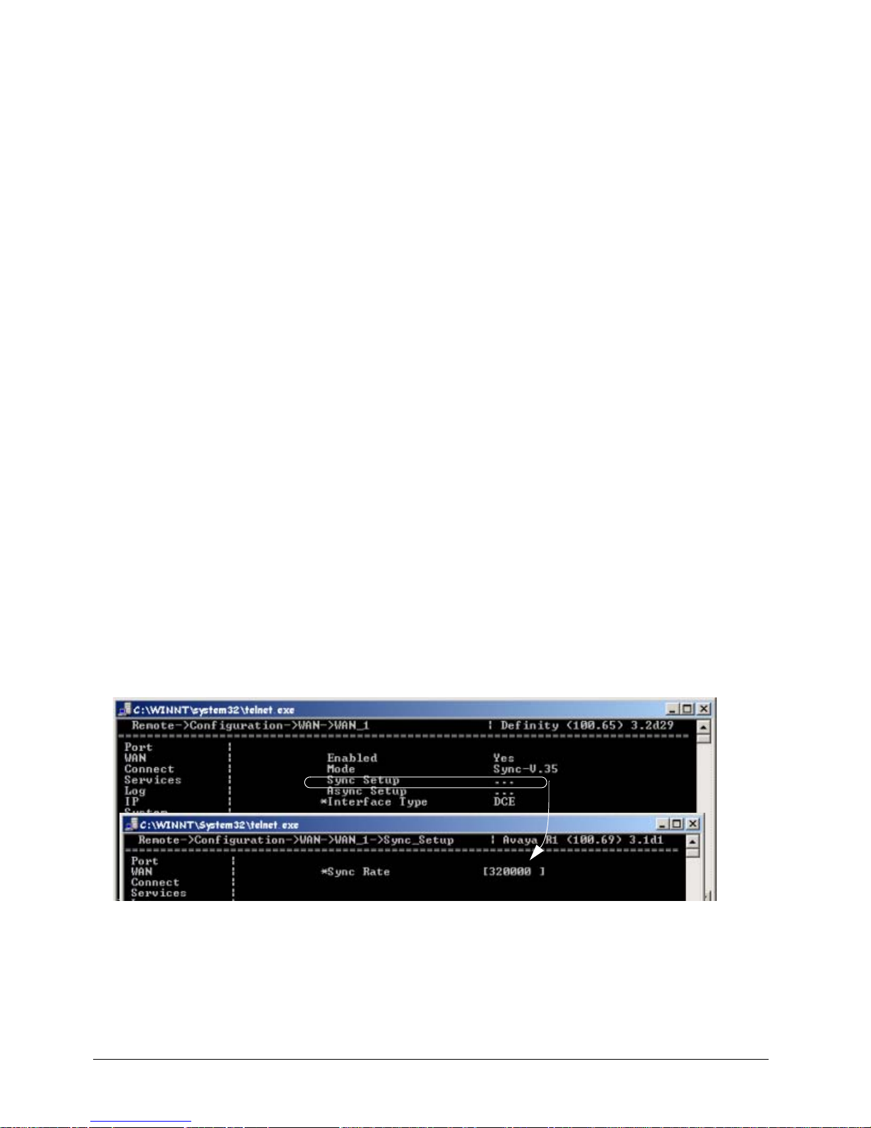
EXTender
TM
7000 Installation Guide Page 52
Add/Drop Application
You can use one of the EXTe nder 7000 WAN ports as an Add/Drop port, which can send traffic to another
network device.
Using the MI, specific DS0 channels of the T1/PRI Port_1 can be mapped to the Add/Drop port. This allows
traffic on those channels to remain unchanged while they are passed through the T1/PRI card to another
device on the network. For an example of the configuration required for a complete Add/Drop application,
see the Add/Drop 6000 and 7000 application in the EXTender 7000 User’s Guide.
Note: Add/Drop application is only available when T1/PRI Port_1 is connected to a T1 Leased Line or a T1
Frame Relay Line.
Add/Drop Configuration
WAN Port Setup
By default the T1/PRI Port_1 is the source port. Either WAN1 or WAN2 must be enabled prior to configuring
the Add/Drop port.
1. Access the WAN menu using the following path:
MI Path
Configuration->WAN->WAN1
2. Set the Enable to Yes. This will enable the selected WAN to receive data dropped from T1/PRI Port_1.
3. Set Mode to Sync-V.35.
4. Set Interface Type to DCE.
Note:
DCE is used in Add/Drop configurations (connecting to an EXTender 6000 or a Router). In DCE installa-
tions, you must use the 25 pin Female-to-Female crossover cable (DB-25, RS-530) that we provide.
5. Access the Sync Setup parameter and enter the Sync Rate (bps). This is the bandwidth that has been
allocated to the Add/Drop Services.
Exampes:
T1 Leased configuration; the sum of DS0s assign as Add/Drop x DS0 rate
T1 Frame Relay configuration; the 'Maximum Bandwidth' assign in PVC setup for Add/Drop.
Figure 4-1: Add/Drop Configuration
Enabling Add/Drop Service
Once the WAN port has been configur ed you need to enable Add/Drop on that WAN port. This is done by
using the Add/Drop services menu.
1. Access the Add/Drop menu using the following path:
Page 53
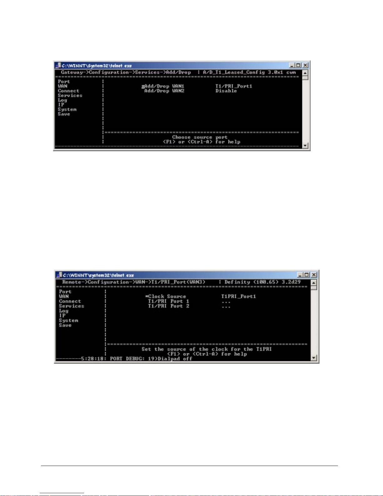
EXTender
TM
7000 Installation Guide Page 53
MI Path
Configuration->Services->Add/Drop
The following menu appears:
Figure 4-2: Enabling Add/Drop
2. Set Add/Drop WAN1 to T1/PRI_Port1.
Add/Drop Configuration for T1 Leased
First the T1/PRI Port parameters must be configured, then the Add/Drop channels.
Add/Drop - T1/PRI Port (WAN3) - Leased T1 Parameters
This section provides instruction for the configuration of the Leased TI line that is connecting the EXTender
7000 to the Gateway.
1. Set the Clock Source parameter to T1PRI_Port1.
• Set to Port 1 if the network is providing timing, or Port 2 to use the EXTender 7000 for the timing
source. Note: Point-to -Point (RVP_Direct) T1’s DO NOT provide timing.
Figure 4-3: Clock Source
2. Go to the T1/PRI Port Setup Menu to perform the basic setup for the T1/PRI ports and channels. This
menu is located in the WAN submenu structure, and can be accessed using the following path:
MI Path
Configuration->WAN->T1/PRI_Port(WAN3)->T1/PRI_Port_1
Page 54
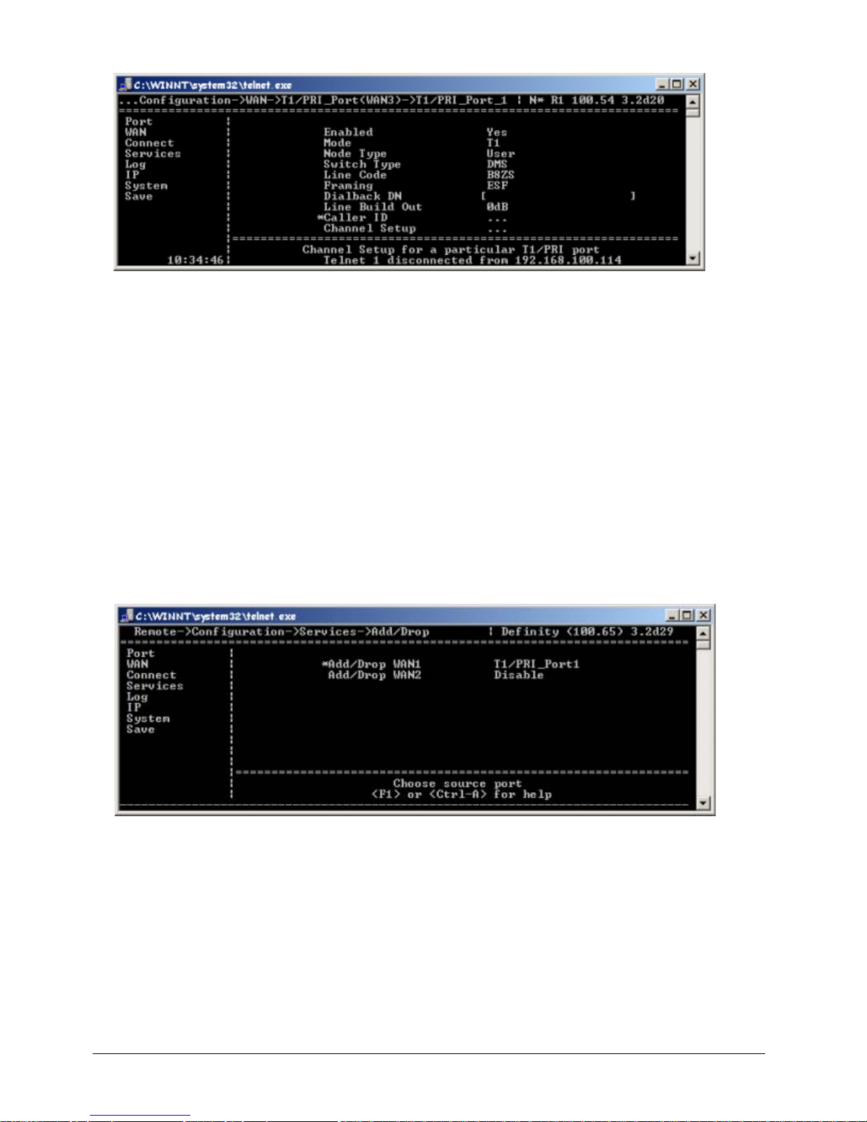
EXTender
TM
7000 Installation Guide Page 54
The following menu appears:
Figure 3-4: T1/PRI Port (WAN3) Parameters
3. Set the Enabled parameter to Yes.
4. Set the Mode parameter to T1.
5. Ignore the following parameters, as they do not apply to Leased T1 configurations: Node Type, Switch
Type, and Dialback DN.
6. Set the Line Code and Framing parameters with values provided by the Telco company (CO).
7. Select a value for the Line Build Out parameter to attenuate the signal before it leaves the extender.
Use a value recommended by the Telco company (CO).
Add/Drop Channels - Leased T1 Parameters
Once the WAN port has been configur ed you need to enable Add/Drop on that WAN port. This is done by
using the Add/Drop services menu.
1. Access the Add/Drop menu using the following path:
MI Path
Configuration->Services->Add/Drop
The following menu appears:
Figure 4-5: Enabling Add/Drop
2. Set Add/Drop WAN1 to T1/PRI_Port1.
MI Path
Configuration->WAN->T1/PRI_Port (WAN3)->T1/PRI_Port_1->Channel Setup->
DSO_x-x
Note: “X” refers to the ports to be assigned for Add/Drop
3. Set Enable to <Default>.
4. Set Direction to <Default>.
Page 55
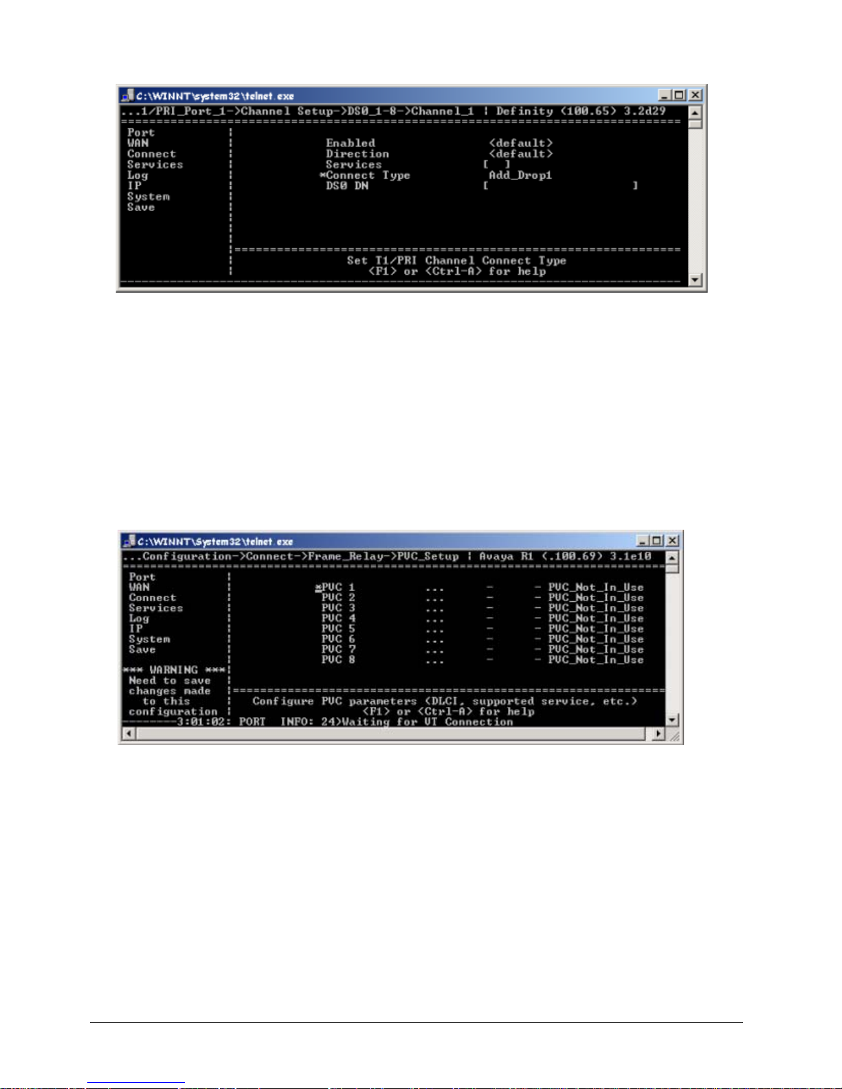
EXTender
TM
7000 Installation Guide Page 55
5. Set Connect Type to Add_Drop1. Note: Add/Drop1 will allocate DS0 channels to WAN1 and Add/Drop2
will allocate DS0 channels to WAN2.
Figure 4-6: Add/Drop Channel Setup
Add/Drop PVC - T1 Frame Relay
T1/PRI Port (WAN3) Configuration - T1 Frame Relay
Please refer to “Add/Drop - T1/PRI Port (WAN3) - Leased T1 Parameters on page’ 53.
Assigning Add/Drop PVC
1. Use the arrow keys to access the following PVC_Setup menu.
MI Path
Configuration->Connect->T1/Frame_Relay->PVC Setup
Figure 4-7: T1/PVC Setup Menu
Page 56
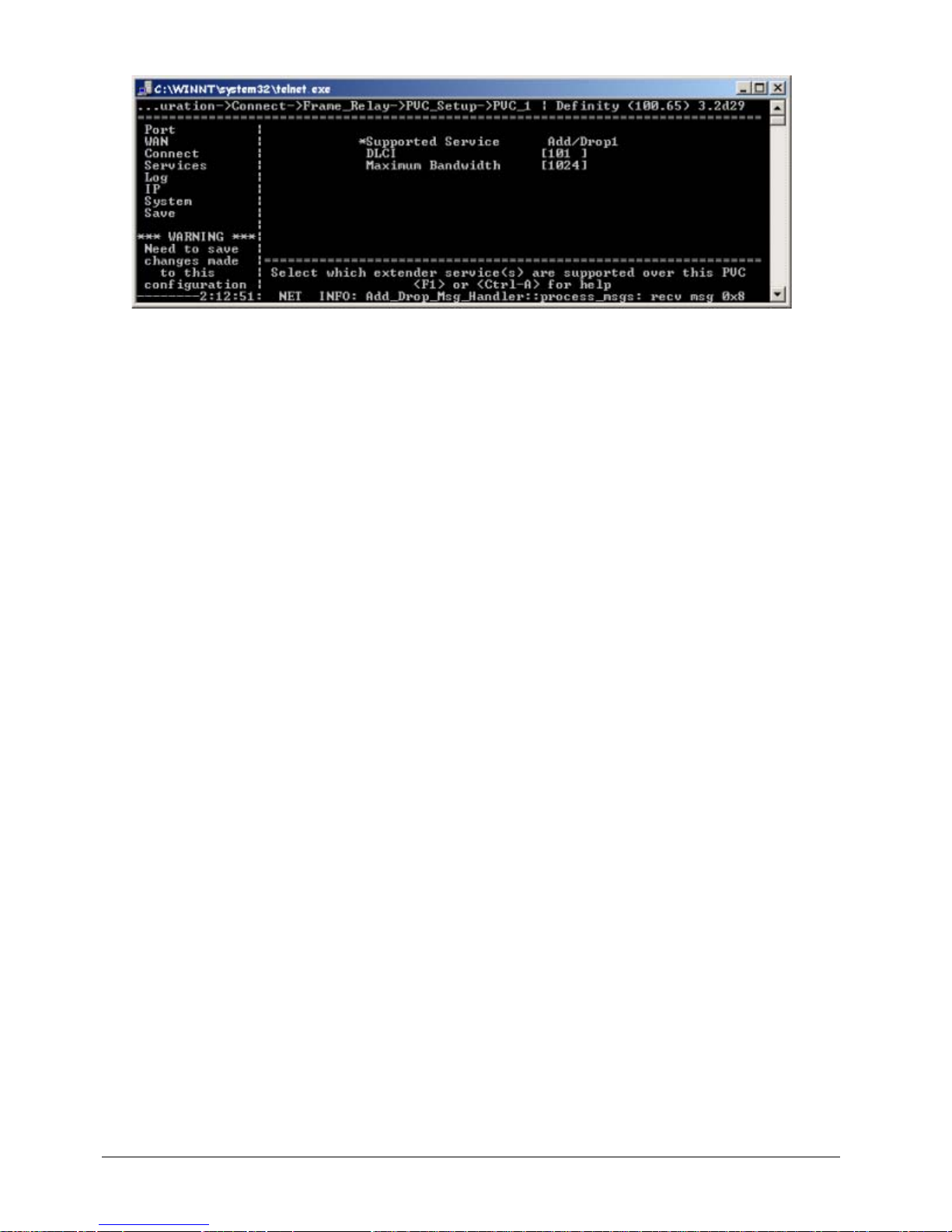
EXTender
TM
7000 Installation Guide Page 56
2. Press the → key to access the PVC parameters screen.
Figure 4-8: PVC_1
3. Set the Voice PVC Supported Service parameter for the EXTender link to Add/Drop1 or Add/Drop2.
Note: Add/Drop1 will allocate DS0 channels to WAN1 and Add/Drop2 will allocate DS0 channels to
WAN2.
4. Set the DLCI (Data Link Connection Identifier) for this PVC (16 - 1007). This number is given to you by
your service provider. The DLCI field defaults to blank and is cleared automatically if you set the PVC
type to "Not In Use."
5. Set the Maximum Bandwidth to the specified amount of guaranteed bandwidth (mea sured in bits per
second) on a Frame Relay service. Use MCK’s Bandwidth calculator.
6. Repeat steps 3 -5 for each additional PVC (ie. Add/Drop PVC(s)).
7. Use the ← and ↓ keys to return to the Save option.
8. Press Enter to save changes to the active config (.rem) file.
Page 57
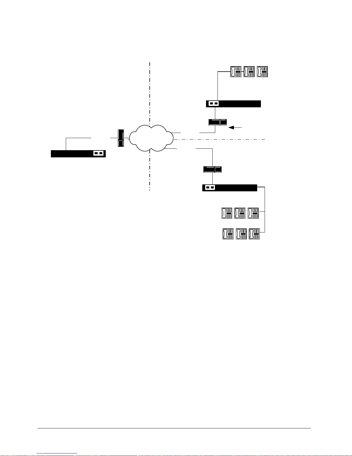
EXTender
TM
7000 Installation Guide Page 57
2 to 1 RVP_Over_IP with Local Dialing Configuration
In this application, two EXTender 7000 units are connected to a single PBXgateway II. The EXTender 7000
units can be in different cities but the connected users share Local Dialing capabilities.
Figure 4-9: 2:1 Configuration using RVPoIP
In this configuration, the left port (labeled Port1) on the MCK T1/PRI card is used as the MCK EXTender link
to the Central Office (CO) to provide Local Dialing. Toll Bypass enables remote users in one city (City A) to
call standard telephones in a different city (City C or B) using the dial tone of the EXTender 7000 that is in
the local calling area. All network connections are provided to the internet via the Ethernet Ports located on
the back of the units.
2:1 RVP_Over IP Consideration
• Maximum number of extended phones that can be operated simulateously is determined by the 'Configuration>Connect>RVP_Over_IP>Extender Voice BW'
• The maximum number of hairpinned calls depends on the DS0s available in the Local PRI line configured in the T1/PRI Port. For a full 23 DS0s PRI service, the system allows 23 hairpinned calls.
• The limitation of maximum de-hairpinned calls depends on the loading of the extender system. By
default, the remote extender is configured to handle 20 de-hairpinned calls (Configuration>Connect>RVP_Over_IP>Local Call BW = 1124150). If problems arise with the configuration, it is necessary
to reduce the maximum number of de-hairpinned calls by assigning different Local Call BW.
To limit the max. de-hairpinned calls use this formula:
Local Call BW = (# of de-hairpin calls x 56145)+1250
Ethernet
960K
Ethernet
660K
Ethernet
300 K
IP
Network
PBXgateway II
EXTender 7000 #1
City BCity A
City C
7000 Telephones
7000 Telephones
EXTender 7000 #2
Router
Router
Router
All EXTender
Traffic
7000 Telephones
Page 58
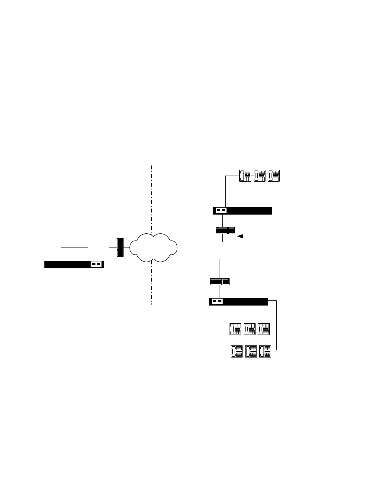
EXTender
TM
7000 Installation Guide Page 58
• Once the Local Call BW has been used up, due to the maximum number of de-hairpinned calls being
reached, further hairpinned calls will retain their hairpinned status when trying to access PBX features.
The phone will display 'PBX Feat Loss', the call will act like a POTs call and will not provide any PBX
features.
• For basic RVP_Over_IP Configuration please refer to “RVP Over IP Configuration on page’ 38.
2:1 Configuration - Computing the Required Bandwidth
In this configuration, the bandwidth in the system must be shared by both EXTender 7000 units. Y ou can still
use the MCK Bandwidth Calculator to compute the ban dwidths required to connect the extended phones to
connect and to support Local Dialing.
The following configuration steps need to be do ne for both EXTender 7000 units. The step s ar e near ly identical for both units (exception: setting the Gateway Port Access p arameter), so the configuration instructions
for the first remote unit will only be shown. When configuration is unique to the second remote unit it will be
clearly indicated in the instructions. This procedure has to be completed for BOTH EXTender 7000s!
Bandwidth Requirements for the EXTended Telephones
In this 2 to 1 configuration, the Extender Bandwidth allocated to the PBXgateway II must equal the Extender
Bandwidth used by both EXTender 7000 units.
Figure 4-10: 2:1 EXTender Bandwidth
Ethernet
960K
Ethernet
660K
Ethernet
300 K
IP
Network
PBXgateway II
EXTender 7000 #1
City BCity A
City C
7000 Telephones
7000 Telephones
EXTender 7000 #2
Router
Router
Router
All EXTender
Traffic
7000 Telephones
Page 59
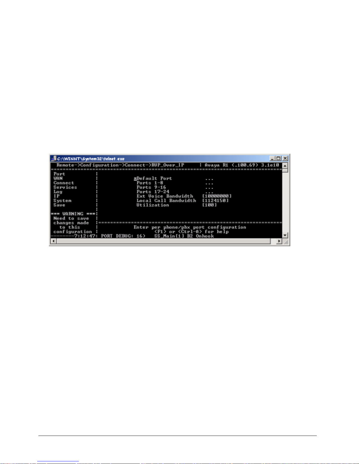
EXTender
TM
7000 Installation Guide Page 59
For example:
PBXgateway II Extender Bandwidth (960K) = 7000 Number 1 Bandwidth (300K) + 7000
Number 2 Bandwidth (660K)
The bandwidth need not be equally divided between the 2 EXTender 7000s. Divide the bandwid th based on
the requirements at each remote of fice location. Use the formula below to compute the bandwidth for each
EXTender 7000:
Bandwidth for EXTender 7000 number 1 = Phone Bandwidth (from Bandwidth Calculator) - Bandwidth for EXTender 7000 number 2.
EXTender Bandwidth Requirements
Use the MCK Bandwidth Calculator to compute the Extender Bandwidth for both remote units.
1. Use the arrow keys (→, ↓ ) to access the RVP over IP menu.
MI Path
Configuration->Connect->RVP_Over_IP
The following menu appears:
Figure 4-11: EXT Voice Bandwidth
2. Use the arrow keys (→ ) to access the Ext Voice Bandwidth, Local Call Bandwidth and the Utilization
parameters.
3. Enter the a portion of bandwidth from the Bandwidth Calcula tor into the Extender Bandwidth parameter. Remember that the Ph one Bandwidth comp uted by the Bandwid th Calculator must be shared
by 2 remote units.
Identifying the EXTender 7000 to the PBXgateway II
1. Use the arrow keys to return to the Connect menu.
2. Access the Remote Number parameter, enter the number of this remote unit. In this configuration the
Page 60
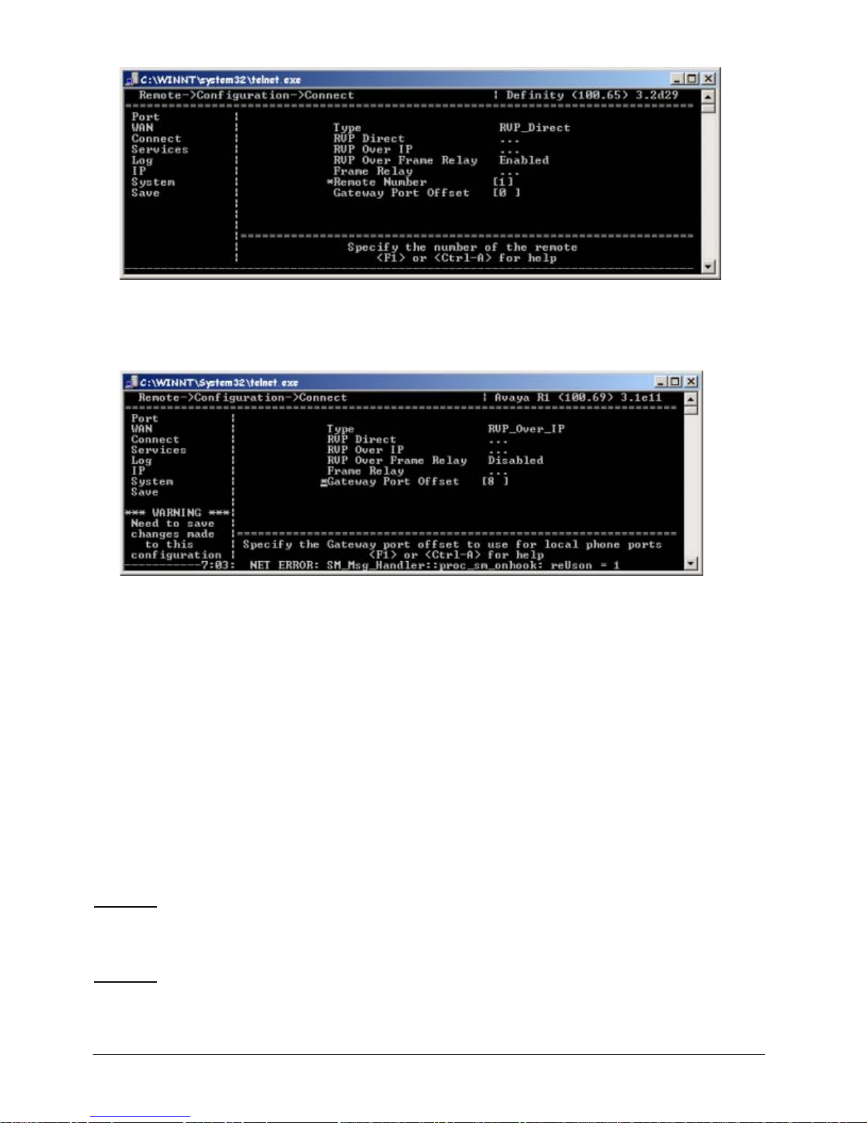
EXTender
TM
7000 Installation Guide Page 60
number for the first EXTender 7000 will be 1, the number for the second unit will be 2.
Figure 4-12: Remote Number [1]
3. Access the second EXTender 7000 and set the Gateway Port Offset. For example, if you have eight
EXTended phones on the first remote set the Gateway Port Offset to 8. This indicates to the second
remote to use ports 9-16 on the Gateway.
Figure 4-13: Gateway Port Offset
4. Use the MCK Bandwidth Calculator to compute the number of local calls in this 2 to 1 configuration.
5. When the calculator computes the num be r of loc al calls that can be made from your extended telephones, simply remember that this number represents the number of local calls that can be made by
BOTH remote units.
De-hairpinned Calls
When a Local Call is made, once it has been established, it will become Hairpinned (status is shown as "H"
on the UI). When the user presses a PBX feature key, the call becomes de-hairpinned (status changes to
“D”) and is directly connected to the PBX. Each de-hairpinned call will use some bandwidth.
Use the MCK Bandwidth Calculator to determine how many "Possible Calls That Can Access PBX Features" for this 2 to 1 configuration. When the calculator computes the number of "Possible Calls that Can
Access PBX Features", simply remember that this number represents "Possible Calls That Can Access
PBX Features" shared by BOTH remote units.
Example:
For example, if the possible number of de-Hairpinned calls is 6, the first EXTender 7000 could allow 4 deHairpinned calls, while the second EXTender 7000 could allow only 2 de-Hairpinned calls.
Example:
For example, if the possible number of Hairpinned calls is 6, the first EXTender 7000 could allow 4 Hair-
pinned calls, while the second EXTender 7000 could allow only 2. Note, the maximum number of
Hairpinned calls is unlimited, de-hairpinned calls is limited to 12 when using RVPoIP.
Page 61

EXTender
TM
7000 Installation Guide Page 61
Setting the Local Dialing Parameters
RVPoIP Limitations
This configuration also uses Voice Hairpinning to maintain local voice quality and to avoid long distance
charges. When Voice Hairpinning is being utilized the voice path is local to the EXTender 7000 and only signalling is sent over the IP network to the PBX (Toll Bypass). When a call is de-hairpinned it is routed in such
a manner that the voice and signalling data are both routed to the PBXgateway II. The PBX will now handle
the call giving the user the PBX features that were not available on the hairpinned call. Note, however that
once a hairpinned call accesses a PBX feature, such as Hold, it will became de-hairpinned.
Please refer to “Configuring the T1/PRI Port for Local Dialing on page’ 62.
2:1 Specific - Local Dialing Configurations
The following items have to be set to enable Local Dialing on BOTH EXTenders.
1. Access the default Local Dialing menu using the following path:
MI Path
Configuration->Port->Default->Local_Dialing
2. Set the Trunk Access Code to match the prefix set in the PBX to access an outside line.
Note: This value will be the same for both EXTender 7000 units.
Page 62
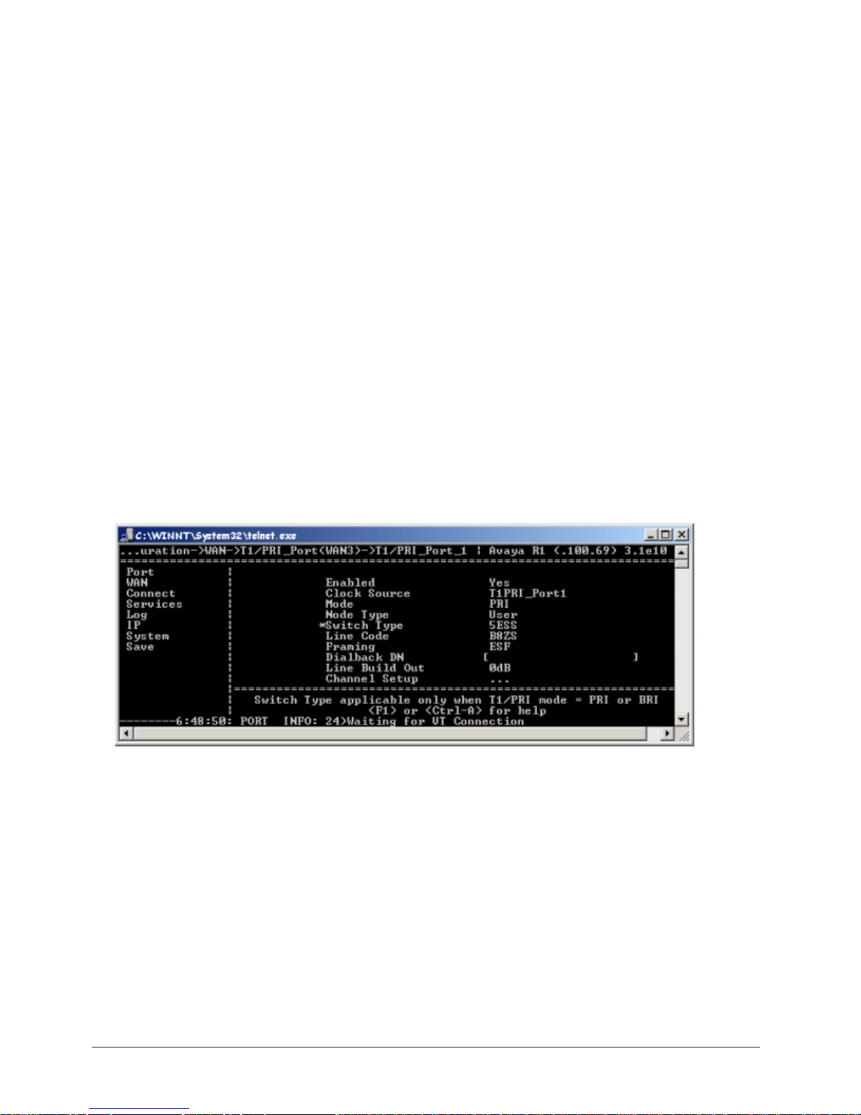
EXTender
TM
7000 Installation Guide Page 62
3. Enter a digit in the Local Access Code. This parameter is a unique prefix that will be attached to the
dial string. This parameter tells the PBXgateway II which EXTender 7000 the call is coming from. You
will need to dial the Local Access Code and the Trunk Access Code when making a local call.
Example:
Trunk Access Code = 9
Local Access Code = 2
To place a local call dial 92 followed by the telephone number you wish to call.
Note: You must use a different Local Access Code for each EXTender 7000.
Synchronizing the MCK T1/PRI card with the Central Office
To synchronize the MCK T1/PRI card with the CO, you need to set the T1/PRI Port parameters located in
the Configuration->WAN->T1/PRI_Port(WAN3) menu structure. Set these values for the T1/PRI port
on the MCK T1/PRI card that will be used for Local Dialing.
Configuring the T1/PRI Port for Local Dialing
This configuration uses the left (Port1) PRI port for Local Dialing. These settings apply to both EXTender
7000 units.
1. Start the MI and access the T1/PRI Port (WAN3) menu with the following path:
MI Path
Configuration->WAN->T1/PRI_Port(WAN3)->PRI_Port_1
The following menu appears:
Figure 4-14: PRI_Port_1
2. Set the Enabled parameter to Yes.
3. Set the Clock Source parameter to T1PRI_Port1.
4. Set the Mode parameter to PRI.
5. Set the Node Type parameter to User.
Note: The T1/PRI card only supports User mode for the DMS switch type.
6. Set the Switch Type, Line Code, and Framing parameters with va lues provided by th e Telco company
(CO).
Note: If you need AMI_ZCS line coding and/or D4 Framing you must use T1PRI_Port2 for local dialing
7. Select a value for the Line Build Out parameter to attenuate the signal before it leaves the extender.
Use a value recommended by the Telco company (CO).
8. Use the arrow keys to access the Channel Setup menu, as shown below:
Page 63
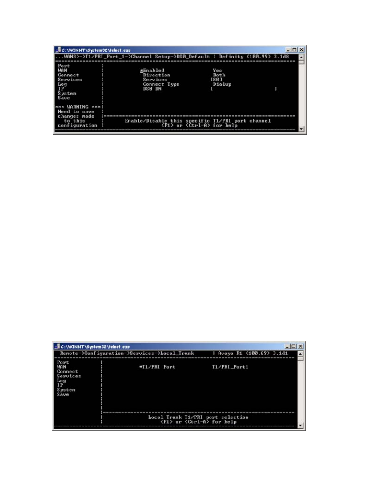
EXTender
TM
7000 Installation Guide Page 63
MI Path
Configuration->WAN->T1/PRI_Port(WAN3)->T1/PRI_Port_1->
Channel Setup->DS0_Default
Figure 4-15: DS0_Default Menu
9. Set the Enabled parameter to Yes.
10. Set the Direction parameter to indicate which direction data will travel. The value Both means the channel will handle both inbound and outbound traffic.
1 1. Enter a two digit integer into the Services parameter. This p arameter ena bles you to select the services
you wish to use to connect to the Central Office (CO). The values most commonly used are 80 (voice
calls) and 82 (64K clear channel).
If you intend to use the port to access local trunks, set the Services parameter to 80.
12. Set the Connect T ype parameter to Dialup.
Verify Successful Synchronization
Once the above settings are configured, then the MCK T 1/PRI card should be able to sync up to the T1 line.
1. Look at the MCK T1/PRI card in the back of the unit. If the CO and the MCK T1/PRI card are correctly
synchronized, the LED on the T1/PRI card should be solid Green.
Identifying the Local Trunk Port
You must identify one of the MCK T1/PRI ports as the Local Trunk port to support Local Dialing.
1. Access the Local Trunk menu using the following path:
MI Path
Configuration->Services->Local_Trunk
This menu has a single parameter: T1/PRI Port.
Figure 4-16: Local Trunk Parameter
2. Set this parameter to T1/PRI_Port 1.
Page 64
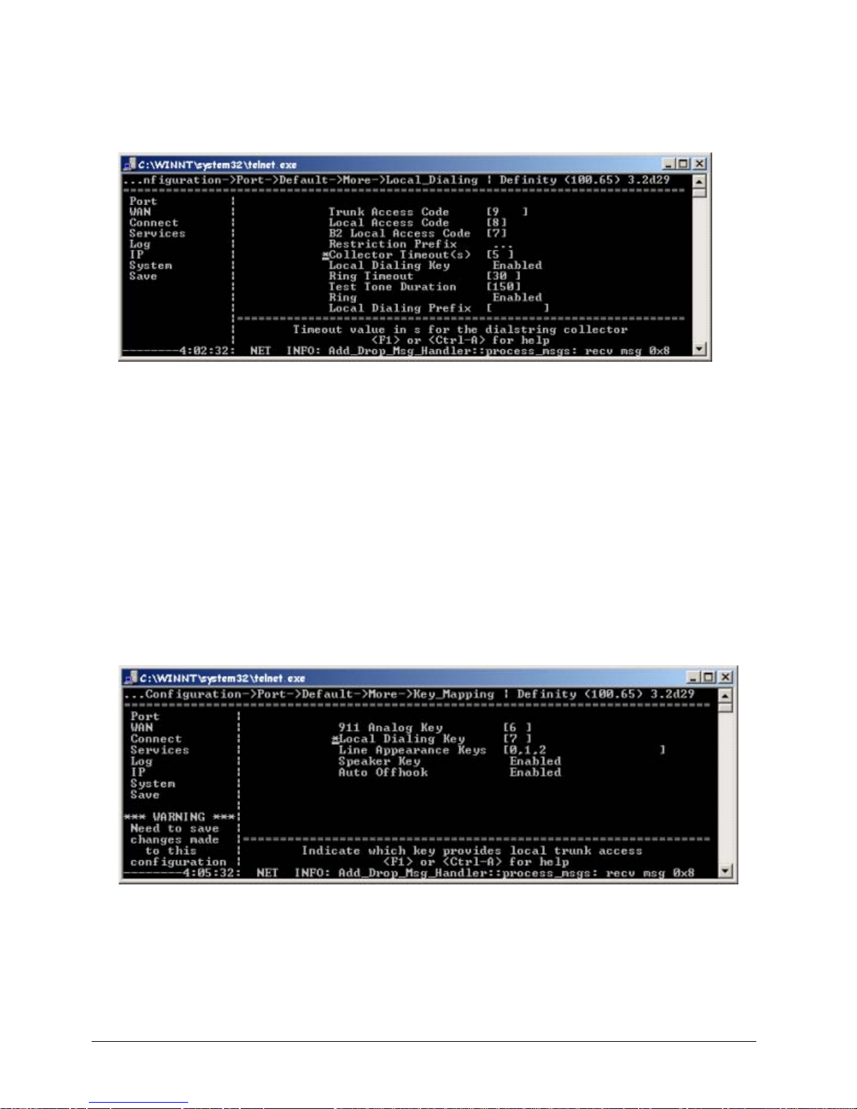
EXTender
TM
7000 Installation Guide Page 64
3. Access the Local Dialing Menu.
MI Path:
Configuration->Port->Default->More->Local Dialing
4. Set the Dial String Collector Timeout parameter correctly. After this time-out period has expired, the
keys pressed by the remote user will be captured and used to facilitate Voice Hairpinning. We recommend a value of 5 seconds.
Figure 4-17: Collector Timeout(s)
Notes:
The Trunk Access Code and Lo cal Access Code parameters are required for Voice Hairpinning in
this 2 to 1 configuration.
If a remote user reports that it takes too long to make a local call, you may have to reduce the Collector
Timeout parameter and the corresponding PBX setting.
5. Use the arrow keys (→, ↓ ) to access the default Key Mapping menu shown below:
MI Path
Configuration->Port->Default->Key_Mapping
6. Use the arrow keys (→, ↓ ) to access the Line Appearance Keys parameter. Set this parameter to
identify the function keys on the remote telephone which indicates the line is active. The remote user
answers a call by pressing a Line Appearance Key.
7. Set the Speaker Key parameter.
8. Make sure the Auto Offhook parameter matches the setting in the PBX.
Figure 4-18: Key Mapping
9. Use the arrow keys to return to the Save option.
10. Press Enter to save changes to the active config (.rem) file.You have completed configuring the first
EXTender 7000 to be used in a 2 to 1 Configuration.
Repeat the steps to configure the second EXTender 7000 unit. Remember that the second remote unit must
Page 65

EXTender
TM
7000 Installation Guide Page 65
have a different Local Access Code from that of the first remote unit. Also be sure to set the Remote Num-
ber of the second EXTender 7000 to 2.
After both EXTender 7000 units have been successfully configured, be sure to properly configure the PBXgateway II to connect to these units in this 2 to 1 configuration. See the PBXgateway II System Administra-
tor’s Guide for instructions.
Page 66
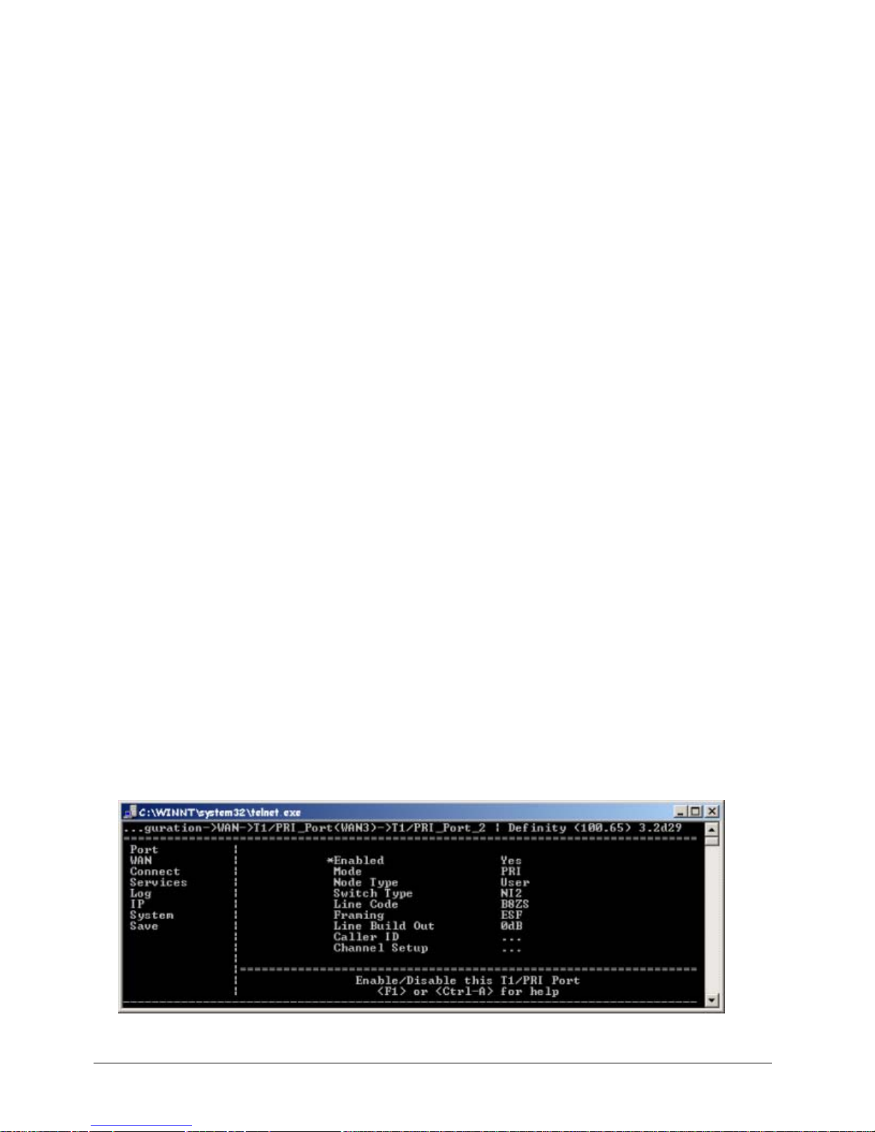
EXTender
TM
7000 Installation Guide Page 66
Local Dialing Configurations
The following pages provide step-by-step instructions for enabling Local Dialing on the EXTender 7000.
Remote user’s can make local calls whether the EXTender 7000 is on-line with the PBXgateway II, or offline. To configure the system, you will set various parameters in the Management Interface (MI).
In order for Local Dialing to function on the EXTender 7000, the extender must be connected to a PBXgateway II that is equipped with the MCK T1/PRI card. See the PBXgateway II documentation for more information.
Notes:
Local Dialing is not supported when the RVP_Direct interface is via the WAN Ports (ie. Connect>RVP_Direct>Primary Interface = WAN1 or WAN2)
Configuration of the EXTender 7000 is fully described in the EXTender 7000 User’s Guide.
Local Hosted Calling (via Predefined Local Trunk Key)
While the Analog Port on the EXTender 7000 provides local dialing, only one remote client can use it at a
time. With a CO (Central Office) line terminated by the T1/PRI Card, multiple remote users can make local
calls simultaneously.
Local Hosted Calls are made when the EXTender 7000 is off-line with the PBXgateway II, they will not have
PBX features. (Hold, Transfer, Conference, etc.)
PBX Hosted Calling
The MCK T1/PRI Card enables local calls to be made and received with minimal toll charges applied. The
supported PBX features are enabled (Hold, Transfer, etc.) but toll charges are kept local. MCK uses local
Voice Hairpinning to reduce the traffic that is sent over the network between the EXTender 7000 and the
PBXgateway II.
Local Dialing Via PRI
Set the Parameters for T1/PRI Port 2
Port 2 on the MCK T1/PRI card serves as the Local CO link.
1. Access the T1/PRI Port 2 menu from the main menu using the following path:
MI Path
Gateway->Configuration->WAN->T1/PRI_Port(WAN3)->T1/PRI_Port_2
The T1/PRI Port menu appears:
Figure 4-19: Local Dialing
Page 67
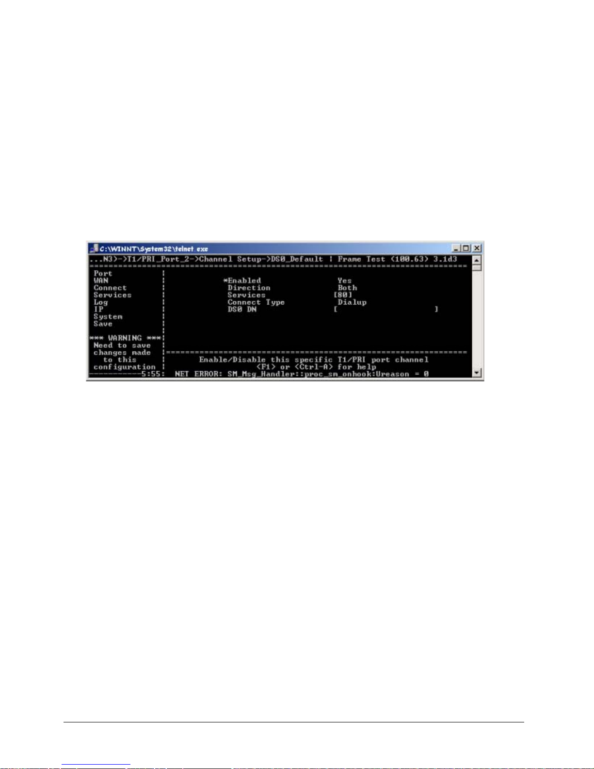
EXTender
TM
7000 Installation Guide Page 67
2. Set the Enabled parameter to Yes.
3. Set the Mode parameter to PRI.
4. Set the Node T ype parameter to User so that the T1/PRI port will be in User Mode.
5. Set the Switch Type, Line Code, and Framing parameters with values provided by the Telco (CO)/
PBX Administrator.
6. Select a value for the Line Build Out parameter to attenuate the signal before it leaves the EXTender
7000. Use a value recommended by the Telco (CO) or PBX Administrator.
7. Use the arrow keys to access the DS0_Default Channel Setup menu, as shown below:
MI Path
Configuration->WAN->T1/PRI_Port(WAN3)->T1/PRI_Port_2->
Channel Setup->DS0_Default
The following menu appears:
Figure 4-20: DS0_Default Channel Setup
8. Set the Enabled parameter to Yes.
9. Set the Direction parameter to Both. This parameter indicates the direction data will travel on the DS0
channel. The value Both means the channel will handle both inbound and outbound traffic.
10. Enter 80 into the Services parameter. This parameter enables you to select the services you wish to
use to connect to the CO/PBX. The value 80 assigns T1/PRI Voice Service to all DS0 channels.
11. S et the Connect Type parameter to Dialup.
Setting the Local Trunk Parameters
You must identify one of the MCK T1/PRI ports as the Local Trunk port.
1. Access the Local Trunk menu using the following path:
MI Path
Configuration->Services->Local_Trunk
This menu has a single parameter: T1/PRI Port.
2. Set this parameter to T1/PRI_Port2.
Set the Local Dialing Parameters
1. For each remote telephone, follow the steps det ailed in “Set the Local Dialing Parameters on page’ 72.
These parameters must be set for each telephone port.
2. When finished, press the ← key to accept changes and go back to the Configuration Menu.
3. Press the ↓ key to the Save parameter .
Page 68
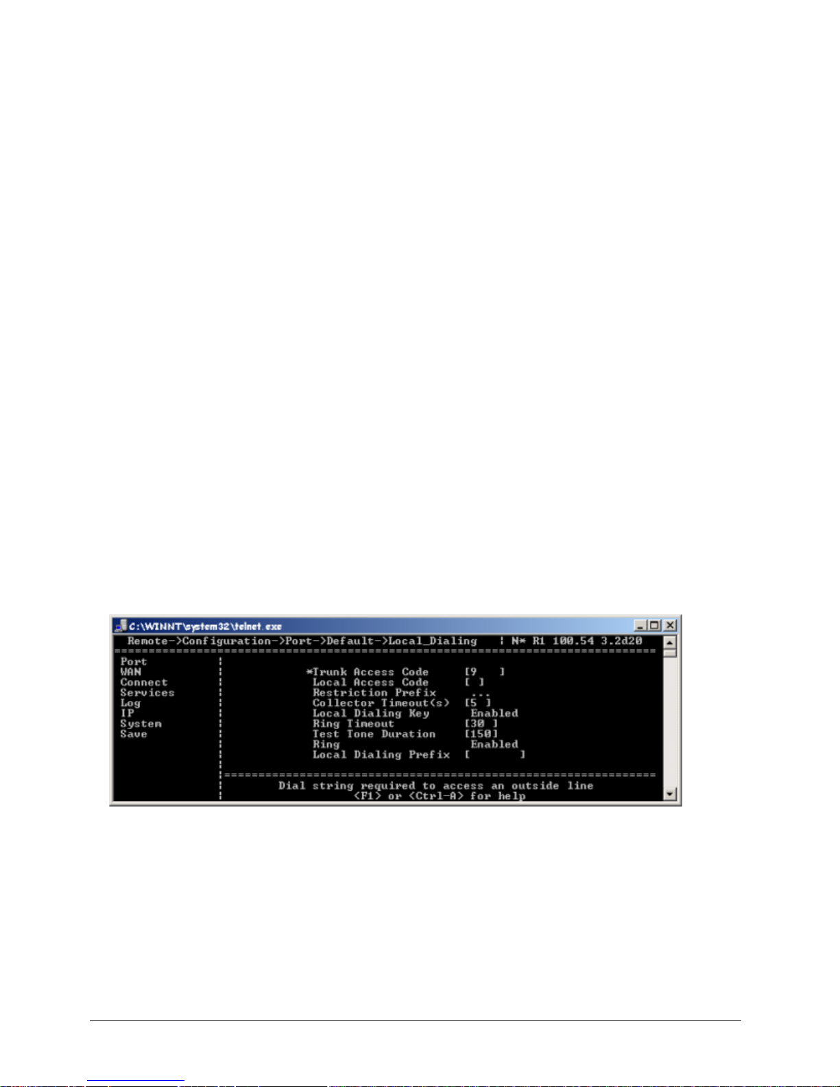
EXTender
TM
7000 Installation Guide Page 68
4. Press Enter to save changes to the active config (.rem) file.
Key Mapping
MI Path
Config->Port->Default->More->Key Mapping
Note: These “Default” Key Mapping settings will set all ports identically.
1. 911 Analog Key: Used to access single analog port.
2. Local Dialing Key: Used to access the local dialing trunk.
3. Line Appearance Keys: Identifies which keys on the extended phone will be the PBX line keys of the
extended PBX port.
4. Speaker Key: Identifies the Hands free mode of the extended PBX port. When enabled, the phone will
provide 'Hands free' capability when using the 911 Analog Key and Local Dialing Key in disconnected
state. Refer to PBX/Phone User Menu for hands free operations.
5. Auto Offhook: Identifies the dialing mode of the extended PBX port.
Default Local Dialing Setup
MI Path
Config-> Port->Default->Local Dialing
Note: These “Default” Local Dialing settings will set all ports identically.
1. Trunk Access Code: Identifies the PBX trunk access code which will route outbound calls via the 7000
system.
2. Local Access Code: Identifies the box number of the 7000; Required when there are 2 remote 7000
units connect to a single Gateway.
3. Restriction Prefix: Used to set restricted access numbers.
4. Collector Timeout: 5 (seconds). Timeout period for the extender to accept user dial string.
5. Local Dialing Key: Enable/disable a phone user to access local dialing via Local Dialing Trunk directly
(by-passing the PBX key).
6. Ring Timeout: 30 - Identifies the ring timeout of an inbound call on the Local Dialing Key
7. Ring: Enable/disable the phone, will ring or not for inbound calls on the Local Dialing Key.
Figure 4-21: Local Dialing
MI Path: Config-> Ports->Ports X-X ->Port X ->More->Local Dialing
Note: These are individual port settings.
8. Trunk Access Code: Code used to dial out from the EXT 7000. (Default Port Only)
9. PBX Extension: The 4-digit extension that corresponds to this port.
10. Restriction Prefix: Used to set restricted access numbers.
11. Collector Timeout: 5 (seconds). Used in conju nction with the Trunk Access Co de. (Default Port Only)
12. Ring Timeout: Timeout (seconds) for local dialing ring. (Default Port Only)
Page 69
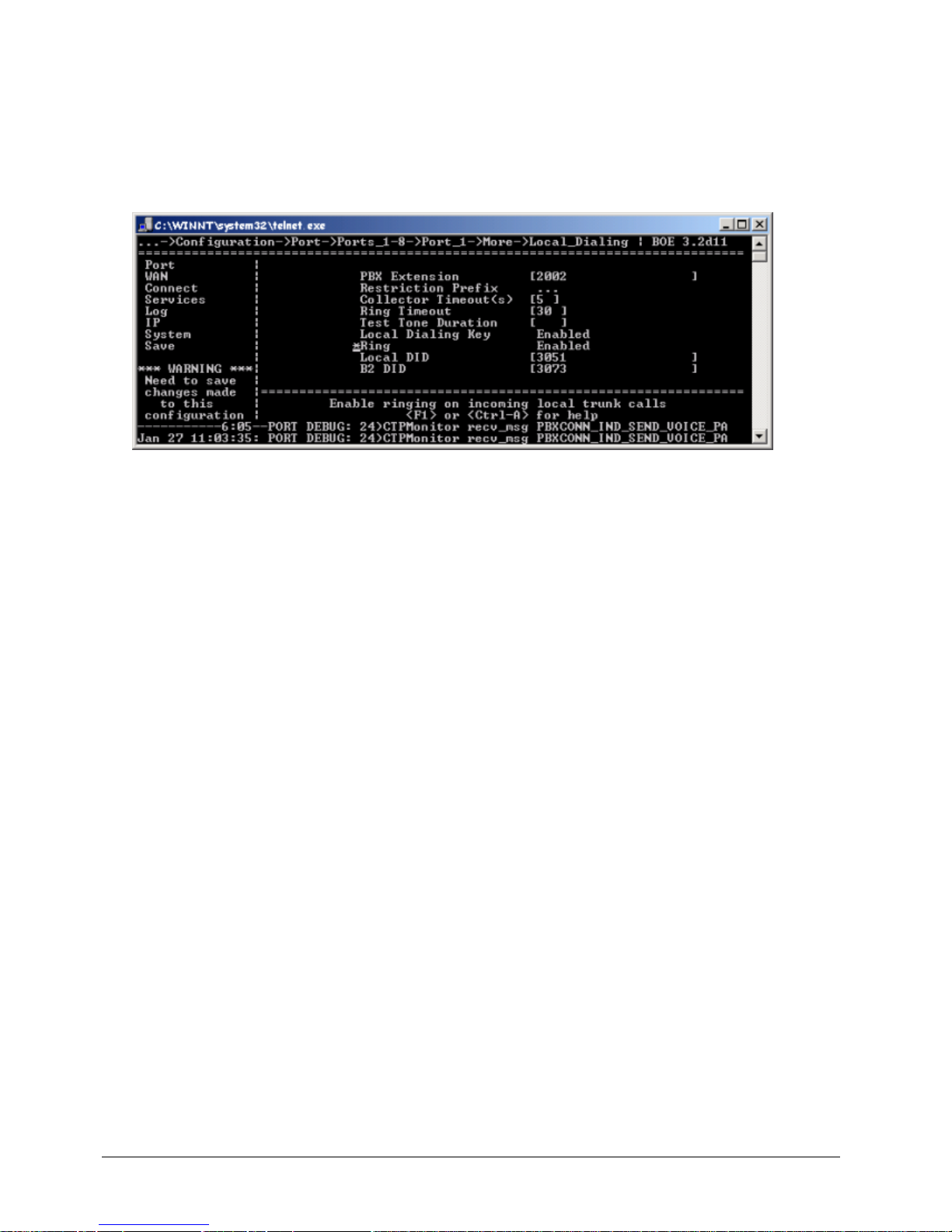
EXTender
TM
7000 Installation Guide Page 69
13. Local Dialing Prefix: This only needs to be configured if it will be used to route a call from a PRI channel
to an analog line, such as ADTRAN 550. It will automatically get prefixed with the dialing digits entered
by the user.
14. Local Dialing Key: Enabled (Default Port Only)
15. Local DID: Direct Inward Dial (DID) number of the extended telephone assigned to this port. This value
is identical to the DS0 DN parameter.
16. B2 DID: Direct Inward Dial (DID) number of the fax assigned to this port.
17. Local Dialing Prefix: The key number that must be entered before the telephone n umber you are dialing
Figure 4-22: Individual Port - Local Dialing
Page 70

EXTender
TM
7000 Installation Guide Page 70
Network Termination (Dual T1/PRI Lines)
T1 Requirements
• Supports AMI encoding on Port 2 for Local Dialing.
• Supports B8ZS encoding.
• Supports D4 superframe (SF) or D4 extended super frame (ESF) framing (on Port2 for Local Dialing).
• Supports both internal and external clocking.
PRI Requirements
• Supports any one of the following protocols;
NI-1, AT&T 4ESS, AT&T 5ESS, or DMS-250
CSU/DSU Functionality
The MCK T1/PRI Card provides integrated CSU/DSU functionality. The card can terminate a T1/FT1 line
and map each DS0 channel of that line to a particular application, based on configuration information
entered by the System Administrator.
Page 71
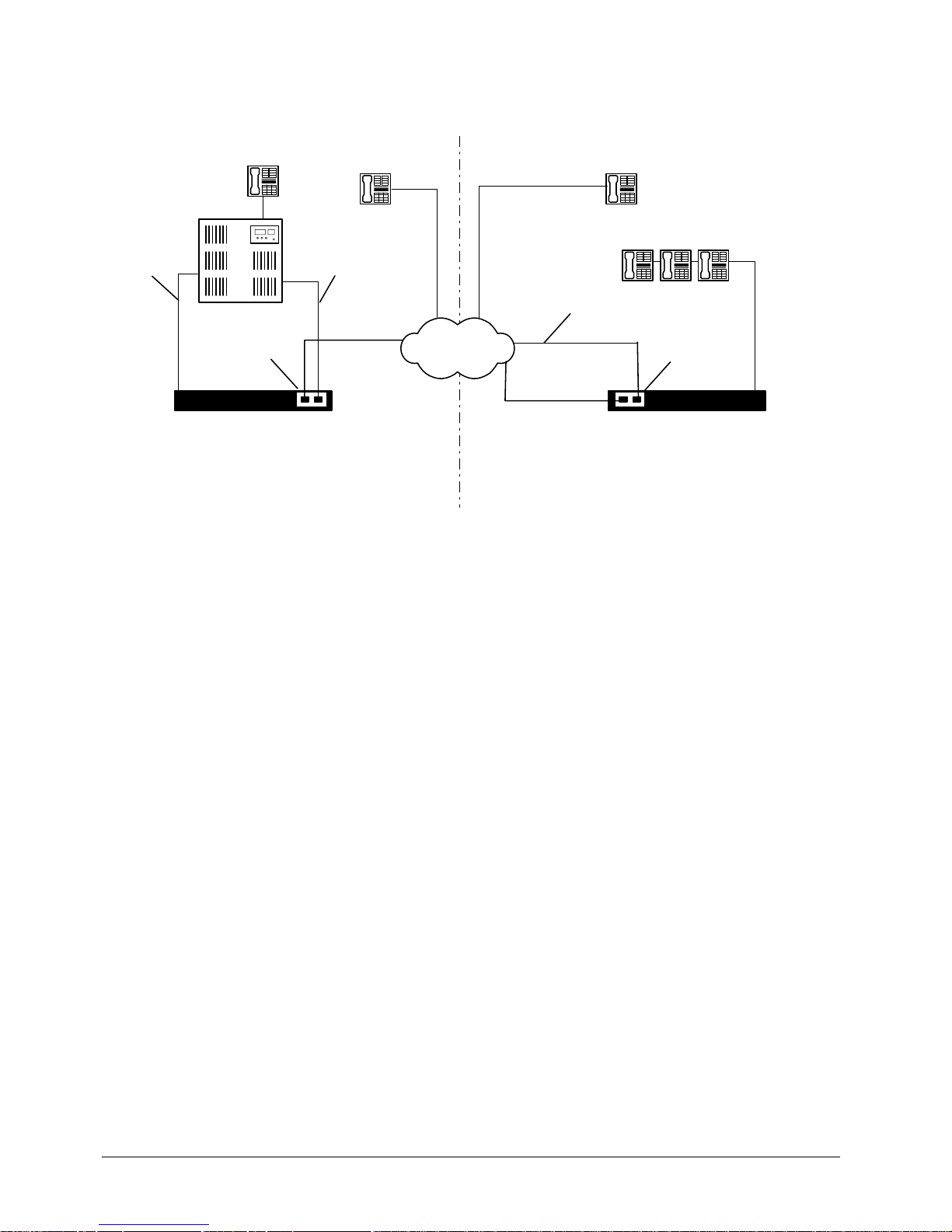
EXTender
TM
7000 Installation Guide Page 71
Separate PRI Configuration
After installation, your system should be connected similar to the figure below:
Figure 4-23: Separate PRI for Local Dialing
Installation
• Connect a straight-through PRI cable from the network to the port labeled Port1 on the MCK T1/PRI
card on the PBXgateway II.
• Connect a crossover PRI cable from the PBX trunk card to the port labeled Port2 on the MCK T1/PRI
card on the PBXgateway II. This is the Digital Trunk Line connnection between the PBX and the PBXgateway II.
• Connect a network interface cable between the Central Office and the port labeled Port2 on the MCK
T1/PRI card on the EXTender 7000.
• Connect a straight-through PRI cable from the network to the port labeled Port1 on the MCK T1/PRI
card on the EXTender 7000.
On the EXTender 7000, the left T1/PRI port (Port1) serves as the MCK EXTender link to the PBXgateway II
over the network. The right T1/PRI port (Port2) connects the Local CO and provides Local Dialing. In a
shared PRI configuration, you can use a single T1/PRI connection to both provide the link to the PBXgateway II and provide Local Dialing via the Local CO. A shared configuration is very economical because only
one T1/PRI line is required at the remote Branch Office.
Prerequisites for Configuration
• The PBXgateway II (at the corporate site) and the EXTender (at the branch office) must be installed
properly and the network link between both devices must be operational.
• The Management Interface (MI) parameters for the PBXgateway II must be set to match the corresponding parameters on the EXTender 7000. See the PBXgateway II System Administrator’s Guide for
detailed instructions.
• If the application will support PBX hosted local dialing, the T1/PRI card in the PBX must be configured
to allow users to access the digital trunk lines. See the PBXgateway II System Administrator’s Guide
and your PBX documentation for instructions.
Branch Office
Standard Telephone
PSTN
Corporate Office
PBX
Local CO Line
(T1/PRI)
PBXgateway II
EXTender 7000
T1/PRI Card
T1/PRI Card
Standard Telephone
Digital Port
City B
City A
Digital Trunk Line
(T1/PRI)
7000 Telephones
Page 72
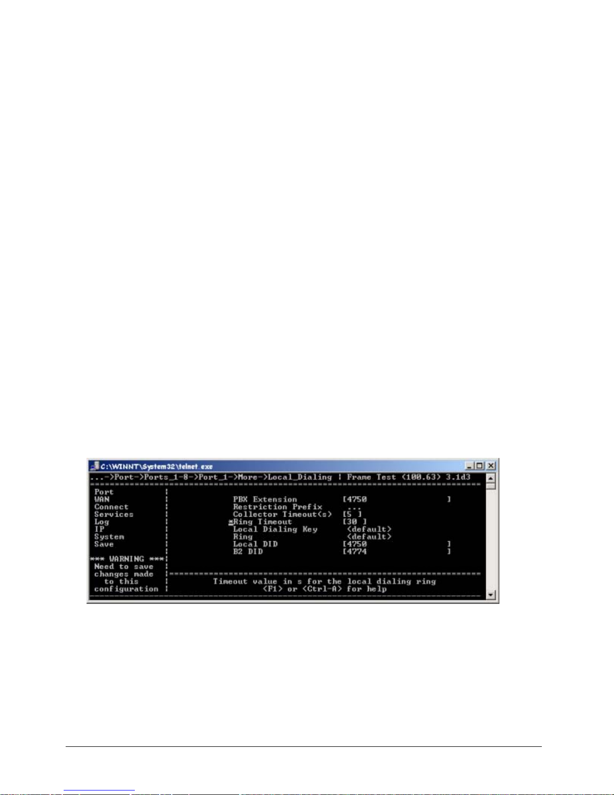
EXTender
TM
7000 Installation Guide Page 72
MI Configuration
Using the MI, you need to:
1. Set the parameters for Port 1 on the MCK T1/PRI card.
2. Set the T1/PRI Service parameters.
3. Set the Connect (RVP_Direct) parameters.
4. Set the parameters for Port 2 on the MCK T1/PRI card.
5. Identify the Local Trunk port.
6. Set Local Dialing parameters.
Identify the Local Trunk Port
You must identify one of the MCK T1/PRI ports as the Local Trunk port.
1. Access the Local Trunk menu using the following path:
MI Path
Configuration->Services->Local_Trunk
This menu has a single parameter: T1/PRI Port.
2. Set this parameter to T1/PRI_Port 2.
Note: In a Shared PRI configuration, you would set this parameter to T1/PRI_Port1, because a single
T1/PRI line is used for both the extended telephones and for Local Dialing.
Set the Local Dialing Parameters
You may want some of the remote telephones to support Voice Hairpinning. For each of these phones, you
have to set parameters in the Local Dialing menu that corresponds to the phone port.
1. Access the Local Dialing menu using the following path:
MI Path
Configuration->Port->Ports_1-8->Port_1->More->Local_Dialing
Figure 4-24: Identifying the Local Trunk Port
2. Set the Trunk Access Code to match the prefix set in the PBX to access an outside line.
3. Set the PBX Extension to the extension that corresponds to this port.
4. Set the Dial String Collector Timeout parameter correctly. After this timeout period has expired, the
keys pressed by the remote user will be captured and used to facilitate Voice Hairpinning. We recommend a value of 5 seconds.
5. For the Local DID parameter, enter the Direct Inward Dial (DID) number of the extended telephone
assigned to this port.
Page 73
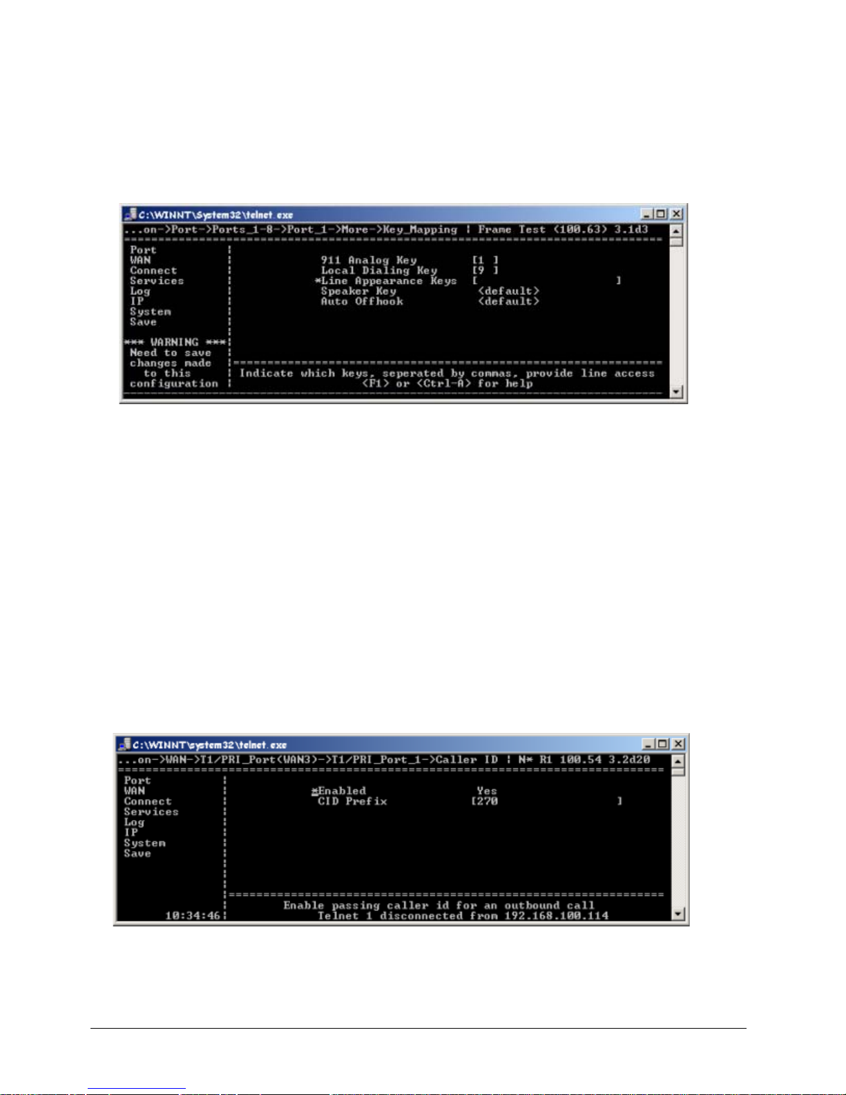
EXTender
TM
7000 Installation Guide Page 73
Notes:
The Trunk Access Code and Collector Timeout parameters are required for Voice Hairpinning.
If a remote user reports th at it takes to o long to ma ke a local call, you may have to reduce the Collector
Timeout parameter and the corresponding PBX setting.
6. Use the arrow keys (→, ↓ ) to access the Key Mapping menu for the port as shown below:
MI Path
Configuration->Port->Ports_1-8->Port_1->More->Key_Mapping
Figure 4-25: Local Dialing Key
7. Enter a value for the Local Dialing Key parameter. When the user presses this line key, he will have
instant access to the local dialing trunk.
8. Use the arrow keys (→, ↓ ) to access the Line Appearance Keys parameter. Set this parameter to
identify the function keys on the remote telephone which indicates the line is active. The remote user
answers a call by pressing a Line Appearance Key.
9. Set the Speaker Key parameter.
10. Make sure the Auto Offhook parameter matches the setting in the PBX.
11. Repeat steps 1 to 10 for each telephone (port) that will support Voice Hairpinning.
12. Use the arrow keys to return to the Save option.
13. Press Enter to save changes to the active config (.rem) file.
Configuring Caller ID
Use the menu path below to configure Caller ID. This will enable Caller ID on all ports using T1/PRI_Port_1
connection between the EXTender and the PBXgateway II. For PBX configuration please consult the PBX-
gateway II System Administrator’s Guide - Chapter 7 - PBX Configuration.
1. Press the → key to access the Caller ID settings.
Figure 4-26: Caller ID
2. Press the → key to set Enable to Yes.
Page 74
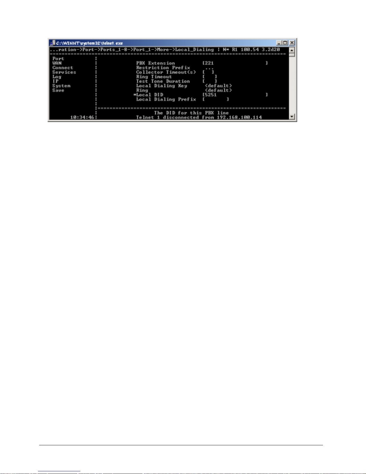
EXTender
TM
7000 Installation Guide Page 74
3. Enter the CID Prefix. This is the prefix included in the Caller ID for the Local Trunk only. The CID Prefix
is used with the Local Dialing (DID) to display the Caller ID.
Figure 4-27: Local Dialing + CID Prefix
4. Repeat this procedure to configure T1/PRI_Port_2 for Caller ID.
Page 75

EXTender
TM
7000 Installation Guide Page 75
Page 76

EXTender
TM
7000 Installation Guide Page 76
Chapter 5: Quick Setup
The following chapter provdes you with a instructions for a quick setup. Detailed configuration for features
and applicaation can be found in Chapters 3 and 4.
Page 77
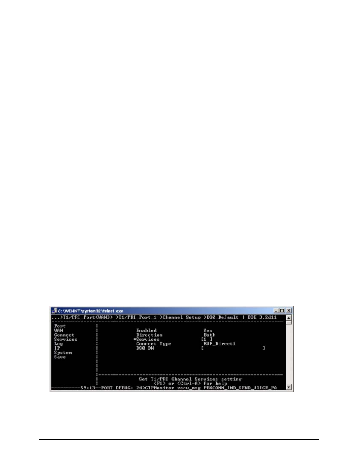
EXTender
TM
7000 Installation Guide Page 77
EXTender 7000 - Quick Setup
Leased Line/Point-to-Point T1
Enabling the PRI Port
Note: Leased Line T1 and Point-to-Point T1 configurations are identical.
MI Path
Configuration -> WAN -> T1/PRI_Port (WAN3)-> T1/PRI_Port_1
Use the procedure below to set the Leased Line/Point to Point T1 parameters.
Procedure:
1. Enabled: Yes.
2. Clock Source: T1/PRI_Port 2
3. Mode: T1
4. The following parameters do not have to be defined:
• Node Type: N/A
• Switch Type: N/A
• Dialback DN
5. Line Code: Value provided by the Telco.
6. Framing: Value provided by the Telco.
7. Line Build Out: Value provided by the Telco.
Setting DSO Default Parameters
MI Path
Configuration -> WAN -> T1/PRI_Port (WAN3)-> T1/PRI_Port_1->Channel Setup >DS0_Default
Note: These “Default” port settings will set all channels identically. The Default settings can be replaced by
accessing and configuring individual port settings.
8. Enabled: Yes
9. Direction: Both
10. Services: 1 (assigns Dedicated T1 service to all DS0 channels)
11. Connect Type: RVP_Direct1
Figure 5-28: DSO Default Parameters
Page 78
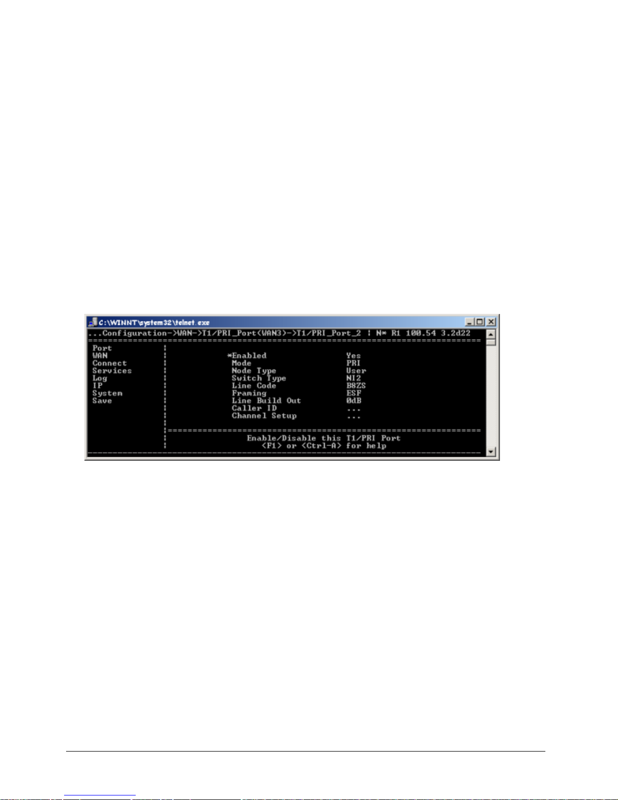
EXTender
TM
7000 Installation Guide Page 78
RVP_Direct Settings
MI Path
Configuration -> Connect -> RVP_Direct
12. Primary Interface: T1_Port1_Leased
13. EXTender BW: Bandwidth required for EXTended phones.
Local Dialing via PRI
Note: In this application, the network between the GII and EXT 7000 is a T1.
MI Path
Configuration -> WAN -> T1/PRI_Port (WAN3)-> T1/PRI_Port_2
Procedure:
1. Enabled: Yes
2. Mode: PRI
3. Node Type: User
4. Switch Type: Value provided by Telco.
5. Line Code: Value provided by Telco.
6. Framing: Value provided by Telco.
7. Line Build Out: 0db or as specified by the Telco.
8. Caller ID: See the EXTender 7000 User’s Guide for instructions on configuring Caller ID.
Figure 5-29: T1/PRI Port 2
Setting the DSO Default Parameters
MI Path:
Configuration -> WAN -> T1/PRI_Port (WAN3)-> T1/PRI_Port_2 ->Channel Setup->
DS0_Default
Note: These “Default” port settings will set all channels identically.
1. Enabled: Yes
2. Direction: Both
3. Services: 80 (to assign PRI voice services to all DS0 channels, or 83 (for DEFINITY)
4. Connect Type: Dialup
5. DS0 DN: N/A
MI Path
Configuration -> Connect -> RVP_Direct
6. Primary Interface: T1_Port1_Leased
7. EXTender BW: Total voice Bandwidth
Page 79
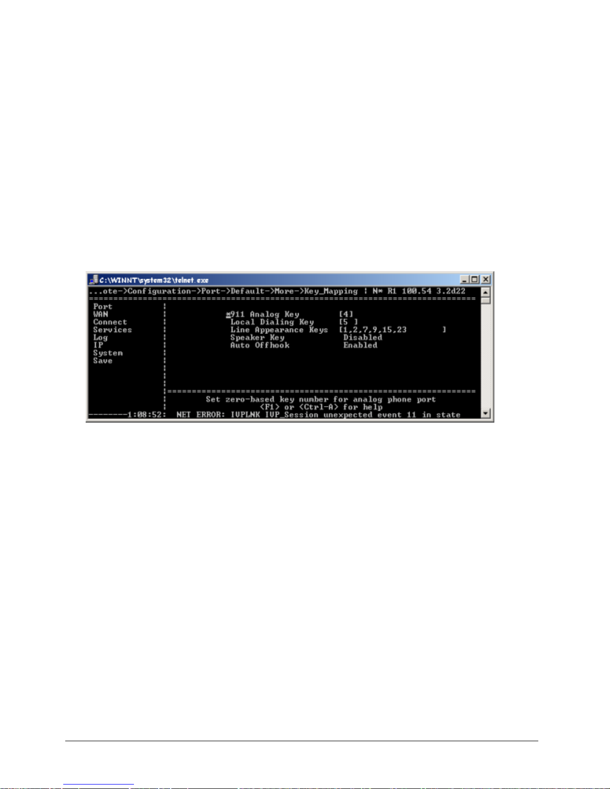
EXTender
TM
7000 Installation Guide Page 79
Setting Local Dialing Parameters
MI Path
Configuration -> Services -> Local Trunk
Note: “X” refers to the Ports used to transport calls across the T1 link.
1. T1/PRI Port: T1/PRI Port 2
MI Path
Configuration -> WAN -> T1/PRI_Port (WAN3)-> T1/PRI_Port_1->Channel Setup->
DS0_X-X
Note: “X” refers to the Ports used to transport calls across the T1 link.
2. Enabled: <Default>
3. Direction: <Default>
4. Services: [ N/A ]
5. Connect Type: EXT_RAW_PCM1
Figure 5-30: DSO Setup
Key Mapping
MI Path
Config->Port->Default->More->Key Mapping
Note: These “Default” Key Mapping settings will set all ports identically.
1. 911 Analog Key: Used to access single analog port.
2. Local Dialing Key: Used to access the local dialing trunk.
3. Line Appearance Keys: Identifies which function keys will indicate the line is active.
4. Speaker Key: Enabled.
Page 80
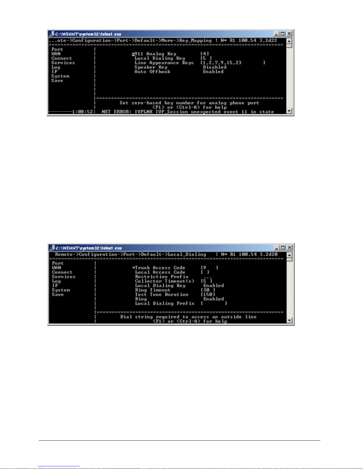
EXTender
TM
7000 Installation Guide Page 80
5. Auto Offhook: Match to PBX Settings
Figure 5-31: Key Mapping
Default Local Dialing Setup
MI Path
Config-> Port->Default->Local Dialing
Note: These “Default” Local Dialing settings will set all ports identically.
1. Trunk Access Code: Code used to dial out from the EXT 7000.
2. Local Access Code: Code to access local trunks.
3. Restriction Prefix: Used to set restricted access numbers.
4. Collector Timeout: 5 (seconds). Used in conjunction with the Trunk Access Code.
5. Local Dialing Key: Enabled
6. Ring Timeout: 30
7. Ring: Enabled
Figure 5-32: Local Dialing
MI Path
Config-> Ports->Ports X-X ->Port X ->More->Local Dialing
Note: These are individual port settings.
8. Trunk Access Code: Code used to dial out from the EXT 7000.
9. PBX Extension: The 4-digit extension that corresponds to this port.
10. Restriction Prefix: Used to set restricted access numbers.
11. Collector Timeout: 5 (seconds). Used in conjunction with the Trunk Access Code.
12. Ring Timeout: Timeout (seconds) for local dialing ring.
13. Local Dialing Prefix: This only needs to be configured if it will be used to route a call from a PRI channel
to an analog line, such as ADTRAN 550. It will automatically get prefixed with the dialing digits entered
by the user.
Page 81
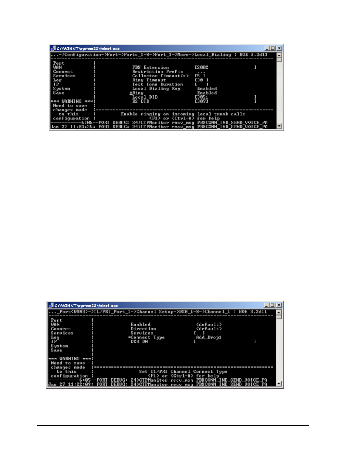
EXTender
TM
7000 Installation Guide Page 81
14. Local Dialing Key: Enabled
15. Ring: Enabled.
16. Local DID: DID number assigned to this port.
Figure 5-33: Individual Port - Local Dialing
Add/Drop Setup
MI Path
Configuration -> Services -> Add/Drop
Procedure:
1. Enabled: Yes
2. Source Port: T1/PRI_Port 1.
3. Destination port: The port on the EXT 7000 that connects to an external device.
MI Path:
Configuration -> WAN -> T1/PRI_Port (WAN3)-> T1/PRI_Port_1->Channel Setup->
DS0_X-X
Note: “X” refers to the Ports to be assigned for Add_Drop.
4. Enabled: <Default>
5. Direction: <Default>
6. Services: [ N/A ]
7. Connect Type: Add_Drop1 or 2, whatever was selected on the Gateway. (Add_Drop1 or 2 is used for
the 2:1 configuration)
Figure 5-34: Add_Drop
MI Path:
Configuration -> WAN -> WAN 1
Page 82
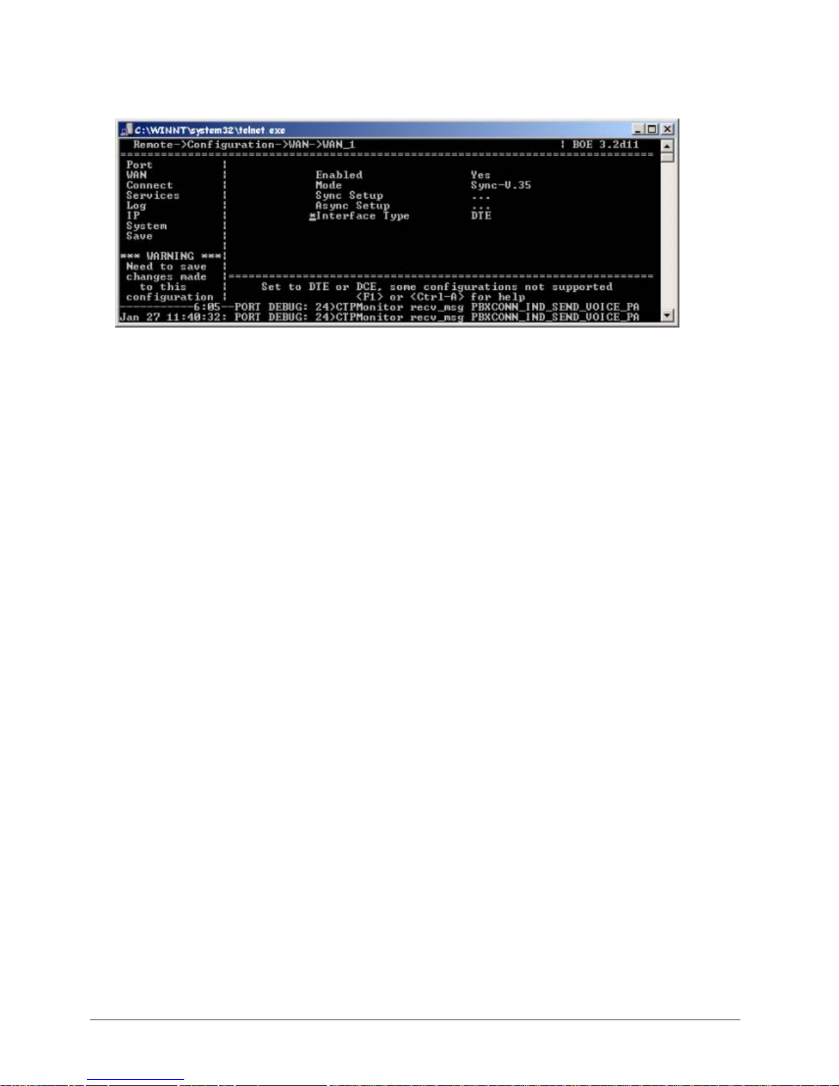
EXTender
TM
7000 Installation Guide Page 82
8. Enabled: Yes
9. Mode: Sync_V.35
10. Sync Setup: Channels assigned for Add_Drop (must match total Add_Dr op BW)
11. Interface Type: DCE or DTE
Figure 5-35: WAN1 Enbaled
Page 83

EXTender
TM
7000 Installation Guide Page 83
Page 84

EXTenderTM 7000 Installation Guide Page 84
Index
A
Add/Drop Application 52
Add/Drop Service
Enabling
52
Add/Drop WAN1 53
Auto Offhook 64, 73
Avaya Definity
Phone Support Types
15
B
Baud Rate Setting 20
C
CIR (Committed Information Rate) 47, 56
Clock Source 27, 47, 53
Collector Timeout 68, 80
Collector Timeout. See Dial String Collector Timeout
COM port settings
20
Connect To Dialog Box 21
Connection Description Dialog Box 20
D
Databits Setting 20
DB-25F 16
DB-25F RS-530 serial cable 16
DB-25M 16
DB-9 RS-232 16
Dial String Collector Timeout 64, 72
Dialback number 37
DID 37
DLCI (Data Link Connection Identifier) 46, 56
DN 1 37
DS0 Channel
Dedicated Service
28, 48
DSO Channel
Assignment Options
48
DSO Default Parameters 77
E
Enhanced Terminal Interface (ETI) 20
Ext Voice Bandwidth 40
EXT_RAW_PCM1 79
F
Flow Control 20
Frame Relay
Interface Parameters
44
Frame Relay Connect Parameters 44
Frame Relay Connections
Verifying
50
Frame Relay Network 43
G
Gateway Port Offset 60
I
IP Destination
PBXgateway
40
IP Parameters
Address
41
Default Router 41
Subnet Mask 41
Web Server 41
L
Leased Line/Point-to-Point T1 77
Leased T1 28
Line Appearence Keys 64, 73
LMI Type
Q.933_Annex_A, ANSI_ Annex_ D
45
Local Access Code 62, 68, 80
Local Call Bandwidth 40
Local Dialing Configurations 66
Local Dialing Key 68, 73, 80
Local Dialing Menu 61
Local DID 72
Local_Trunk 67
M
Management Interface (MI) 23
Mode 31
N
n391
LMI T1 Parameter
46
n392
LMI T1 Parameter
46
n393
LMI T1 Parameter
46
Network Termination
Dual T1/PRI Lines
70
Nortel Norstar Phones 15
P
Parity Setting 20
PBX Extension 72
Page 85

EXTenderTM 7000 Installation Guide Page 85
Primary Dial Num 1 37
Primary Dial Numbers 37
Primary Interface
RVP_Direct via WAN
30
PVC Parameters 46
Q
Quality of Service (QoS) 43
R
Remote Number 59
Restriction Prefix 68, 80
Ring Timeout 68, 80
RJ-45 Cat 5 Ethernet cable 16
RS-232 14
RS-530 14
RVP (RVP_Direct) via WAN - Connect Parameters
30
RVP Direct Menu 59
RVP Over IP Configuration 38
RVP_Direct Parameters
Via PRI
26, 34
RVP_Over_IP
Connect Parameters
39
S
Secondary Interface
RVP_Direct via WAN
30
Separate PRI Configuration 71
Serial Console connection
COM port settings
20
RS-232 cable 20
Serial RVP Installation
T1/PRI Ports on T1/PRI Card
26
Services
64K clear channel
63
voice calls 63
Services Parameter
Frame Relay
28, 37, 48
Setting Local Dialing Parameters 79
Setup Wizard 24
Stopbits 20
Sync Rate 31
T
T1 Configuration 78
T1/PRI Port Setup Menu 27, 47, 53
t391
LMI T1 Parameter
46
TCP/UDP Port Requirements
for Extending Digital Telephones
38
for Local Dialing 39
Trunk Access Code 61, 68, 72, 80
U
Utilization 40
V
V.35 14
Voice PVC Supported Service 46, 56
VT-100 Program 22
W
WAN Port - Setup for RVP_Direct 31
WAN port menu
DCE Interface Type
33
DTE Interface Type 33
 Loading...