

MCK EXTender 4000 Installation Manual

TM
Quality is our job. Customer satisfaction is our mission!
EXTender
4000
Universal Quick Installation Guide
G-4000P-RXM Rev AF
Nov 8, 2006

Copyright
© Copyright 2005 Citel Technologies All rights reserved.
No part of this publication, including text, examples, diagrams, or icons, may be reproduced, transmitted,
or translated in any form or by any means, electronic, mechanical, manual, optical or otherwise, for any
purpose, without prior written permission of Citel Technologies.
Information in this publication is subject to change without notice. Citel Technologies may have patents or
pending patents applications, trademarks, copyrights, or other intellectual property rights covering subject
matter in this publication. The furnishing of this document does not give you license to these patents,
trademarks, copyrights, or other intellectual property.
Trademarks
© Copyright 2005 Citel Technologies All rights reserved.
MCK, the MCK logo, PBXgateway I, PBXgateway II, MCK EXTender 1000, MCK EXTender 3000, MCK
EXTender 4000, MCK EXTender 6000 and MCK EXTender 7000 are trademarks or registered
trademarks of Citel Technologies or its wholly-owned subsidiaries in the United States and other
jurisdictions. All other trademarks, registered trademarks and service marks are the property of their
respective owners.
EXTender 4000 Universal Quick Installation Guide 2

Table of Contents
Table of Contents...........................................................................................................................3
Purpose of this Document ............................................................................................................ 4
Safety Considerations...................................................................................................................... 4
Support Telephone Numbers........................................................................................................... 4
Introduction ....................................................................................................................................5
Specifications.................................................................................................................................6
Prerequisites for Installation.........................................................................................................7
Networking ....................................................................................................................................... 7
TCP/UDP.......................................................................................................................................... 7
Remote Location .............................................................................................................................. 7
Gateway Location ............................................................................................................................ 7
Power and Wiring............................................................................................................................. 7
Installation Components...............................................................................................................8
Parts NOT Included with the EXTender 4000.................................................................................. 8
Typical Installation............................................................................................................................ 8
Location............................................................................................................................................ 8
Compatible Telephones.................................................................................................................9
Connections .................................................................................................................................11
Power-Up.......................................................................................................................................12
Configuration using the Telephone Interface...........................................................................13
Introduction .................................................................................................................................... 13
Required Settings........................................................................................................................... 13
Accessing the Phone Set Interface................................................................................................ 14
How to access the telephone-set interface .................................................................................... 14
Menu Log ....................................................................................................................................... 14
Menu Log, continued...................................................................................................................... 15
Menu Structure............................................................................................................................... 16
Main Legend ..................................................................................................................................17
User ID Menu ................................................................................................................................. 18
IP Menu.......................................................................................................................................... 19
Admin Password Menu .................................................................................................................. 20
Saving Configuration Changes ...................................................................................................... 20
Configuration using the Management Interface (MI)................................................................ 21
IP Call-Suspend Setup................................................................................................................... 21
Procedure....................................................................................................................................... 21
Placing a Call................................................................................................................................23
Press ‘1’ to connect............................................................................................................ 23
Optional Configuration................................................................................................................23
Remote Telephone Messages ....................................................................................................... 24
EXTender 4000 Universal Quick Installation Guide 3

Purpose of this Document
This document provides instructions to install, configure, and troubleshoot the EXTender 4000 single
client device.
Safety Considerations
IMPORTANT SAFETY INSTRUCTIONS
• Do not install this product near water.
Example: In a wet basement location.
• Do not overload wall outlets, as this can result in the risk of fire or electrical shock.
• Do not attach the power supply cord to building surfaces. Do not allow anything to rest on the
power cord. Do not place this product where anyone can step on the cord.
• Do not operate the system if chemical gas leakage is suspected in the area. Use a telephone
located in another, safe area to report the trouble.
Support Telephone Numbers
For Customer Support please contact MCK technical assistance at 1-888 454-5828 between 8:30am 8:00pm (EST). If you are outside North America please dial 1-617-454-6192.
EXTender 4000 Universal Quick Installation Guide 4

Introduction
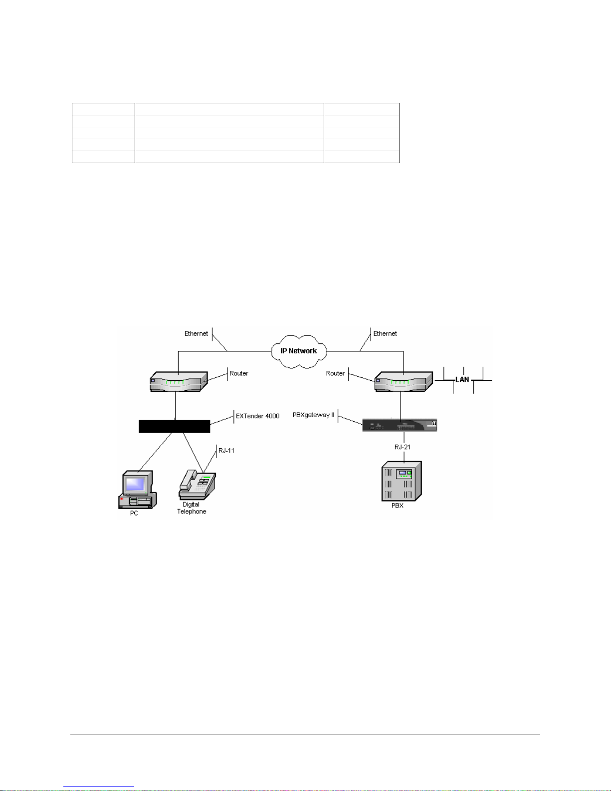
The EXTender 4000 provides remote voice access to a corporate system for a single remote user.
Remote users can connect to a PBXgateway™ via a 10Base-T Ethernet connection using IP packet
transmission.
The remote users’ telephones connect to the EXTender 4000 via an RJ-11 telephone jack. The user’s
telephone traffic is placed in IP packets and sent out to the corporate LAN and then to the PBXgateway
via a 10Base-T Ethernet connection in the PBSX gateway.
The EXTender 4000 provides a choice of three voice compression algorithms: G711, G729A, and G726
(24 and 32 Kbps ADPCM options) to reduce bandwidth requirements. The EXTender 4000 extends the
full functionality of the system to a remote location, via IP over a LAN.
All voice traffic and signaling information from the digital telephone system is packetized by Remote Voice
Protocol (RVP
voice packets can share the Ethernet network with other common data devices. The remote user can also
connect a PC to the LAN through an RJ-45 Ethernet jack on the EXTender 4000, which acts as a hub.
The voice and signaling traffic is transmitted over the LAN between the EXTender 4000 at the remote
location and the PBXgateway at the central location. At the Gateway, the packets are converted back into
the system protocol and sent to the system via an RJ-21 cable.
IP-based products utilize Voice over IP (VoIP) technology to deliver remote voice solutions. The voice
quality of these solutions depends on variables such as available bandwidth, network latency, and Qu ality
of Service (QoS) initiatives, all of which are controlled by the network and internet service providers.
Because these variables are not within our control, we cannot guarantee the perform ance of the user’s
IP-based remote voice solution.
TM
). These packets are encapsulated into IP packets and sent out over the Ethernet. The
EXTender 4000 Universal Quick Installation Guide 5

Specifications
Regulatory Approvals
FCC Parts 15 & 68, Subpart B, Class B
NRTL/C CSA Standard C22.2 No.0-M91, 225-M90
Industry Canada CS-03
UL Standard 950
System Architecture
CPU Motorola 68EN302, 20MHz
DSP Analog Devices 2187, 52 MIPS
Memory
DRAM 2MB
Flash Memory 2MB
Boot ROM 512KB
Ethernet Port
Protocol RJ-45, Ethernet (used for RVP over IP)
Interface 10Base-T
IP Addressing DHCP and Static
Interfaces
Telephone RJ-11
Voice
Voice compression G.729a, G.711, G.726 (ADPCM 32 and ADPCM 24
Protocols and Services
LAN RVP over Internet Protocol (IP)
Electrical
Line Voltage 120V AC Adapter
Environment
Temperature 32° – 130°F (0° – 55°C)
Relative Humidity 5 to 95%
Dimensions
6.3 in. x 5.3 in. x 1.4 in.
160 mm x 135 mm x 34.5 mm
Weight
300 g
EXTender 4000 Universal Quick Installation Guide 6

Prerequisites for Installation
You must meet the following requirements before installing the EXTender 4000:
Networking
• An appropriate network-terminating device must be installed and functioning at both the corporate
facility and the branch office.
• The data connection between the corporate facility and the EXTender 4000 must be operational
and configured properly.
• The network termination equipment must support a 10Base-T Ethernet interface.
TCP/UDP
Ensure that the correct TCP/UDP ports are opened to allow the EXTender 4000 to connect through your
company firewall. The following TCP/UDP port requirements must be met:
Remote Location
The EXTender 4000 uses port 12,288 for incoming UDP streams and any port between 1024 and 65535
for outgoing TCP streams.
Gateway Location
The Gateway unit uses TCP/UDP port 2698.
Power and Wiring
The system is designed to operate at 120 VAC. Do not apply power to the EXTender 4000 until you are
instructed to do so in the installation procedure.
• Install the EXTender 4000 power supply and cabling away from high power/high RF noise devices
such as computers, fans, fluorescent ballast, and power supplies.
• Use good wiring practices. Do not run wires over fluorescent lights, computers, air conditioners,
etc. as this can introduce noise.
• The distance between the telephones and the EXTender 4000 should NOT exceed 500 feet.
EXTender 4000 Universal Quick Installation Guide 7
Installation Components
Quantity Description Provided
1 EXTender 4000 Quick Installation Guide Yes
1 EXTender 4000 unit Yes
1 12VDC Power Supply Yes
1 CAT 5 Ethernet cable Yes
Parts NOT Included with the EXTender 4000
• Digital telephones and cabling
• Routers - Use routers if you want to access to the Remote/Gateway system from outside the local
network.
See page Error! Bookmark not defined. for a list of compatible telephones.
Note: Use two-wire digital display telephones only.
Typical Installation
Figure 1 shows a typical installation of the EXTender 4000.
Location
You can place the EXTender 4000 on any desktop, within 6 feet of an electrical outlet. Follow the Safety
Considerations
EXTender 4000 Universal Quick Installation Guide 8
on page . 4
Figure 1: Typical Installation
 Loading...