


G-3000U-MUM Rev AA
June 09, 2003
MCK EXTender™ 3000
Quick Installation Guide
Quality is our job. Customer Satisfaction is our mission!


EXTender 3000 Quick Installation Guide
Table of Con tents Page 1
Table of Contents
Copyright Information ..................................................................................................................... 3
Definity - Instal ling the Office Mod u le ..... ........................... ........................................... 5
Pre-Installation Checklist ............................................................................................................................ 5
ISDN Li n e Ch ecklist .......................................... ............................... .......................................................... 5
Installation Procedure .................................................................................................................................. 6
Definity - Configurin g the Office Module................ ...................... ..................... ............................ 8
Pre-Co n f i gu r a ti on C he ck l is t ................ ....................................... ................................................................. 8
Configuration Procedure ............................................................................................................................. 8
Acces sin g th e Termina l C on f i gur ation Men u ........ ............................... ................................ ................... 8
For dialup data type only: ........................................................................................................................ 8
Definity - Installing the Remote Module ............................................................. .......................... 10
Pre-Installation Checklist .......................................................................................................................... 10
Installation Procedure ................................................................................................................................ 10
Definity - Configuring the Remote Module................................................................................... 12
Pre-Co n f i gu r a ti on C he ck l is t ................ ....................................... ............................................................... 12
Configuration Procedures .......................................................................................................................... 12
Configuration by Telephone ........ ........... .......... .......... ............................. ............................. ..................... 13
To Go Online ......................................................................................................................................... 15
To Go Offline (Disconnect) ................................................................................................................... 15
LED Bl i nk S eq u en ces ...... .. .......... ............................... ................................ .............................................. 16
Definity - EXTender 3000 Menu................................................................................................... 17
Remote Module Syste m Flowchart ............. ........ ................... .................................... ............................... 17
Definity - Troubleshooting the Remote and Office Modules........................................................ 22
Norstar/Meridian - Installing the Office Module......................................................... 24
Pre-Installation Checklist .......................................................................................................................... 24
ISDN Li n e Ch ecklist ......................... ............................... ....................................... .................................. 24
Installation Procedure ................................................................................................................................ 25
Norstar/Meridi an - Configuring the Office Module................................................... .................... 27
Pre-Co n f i gu r a ti on C he ck l is t ................ ....................................... ............................................................... 27
Configuration Procedure ........................................................................................................................... 27
Acces sin g th e Termina l C on f i gur ation Men u ........ ............................... ................................ ................. 27
For dialup data type only: ...................................................................................................................... 27
Norstar/Meridi an - Installing the Remote Module.............................................. .......... ................. 29
Pre-Installation Checklist .......................................................................................................................... 29
Installation Procedure ................................................................................................................................ 29

Page 2 EXTender 3000 Quic k In stallation Guide
Table of Conte nts
Norstar/Meridi an - Configuring the Remote Module ................. ........... ................................ ........ 31
Pre-Co n f i gu r a ti on C he ck l is t ................ ....................................... ............................................................... 31
Configuration Procedures .......................................................................................................................... 31
Configuration by Telephone ........ ........... .......... .......... ............................. ............................. ..................... 32
To Go Online ......................................................................................................................................... 33
To go Offline (Disconne ct) ........................... ...................... ................................ ................................... 33
LED Bl i nk S eq u en ces ...... .. .......... ............................... ................................ .............................................. 34
Norstar/Meridian - EXTender 3000 Menu..................................................................................... 35
Remote Module Syste m Flowchart ............. ........ ................... .................................... ............................... 35
Norstar/Meridi an - Troubleshooting the Remote and Office Modules.......................................... 40

EXTender 3000 Quick Installation Guide
List of Tables Page 1
List of Tables
Table 1: Definity Configuration Menu ........................................................................................................... 9
Table 2: Definity Key Mapping .................................................................................................................... 13
Table 3: D efi n it y Ru nn i n g Ex t en d er LED Indic at o r Se q uences ....................... ................. ................. .......... 16
Table 4: Definity T r oubleshooting the Remote and Switch ............. .................. ........... .......... .................. ... 22
Table 5: Norstar/Meridian Configuration Menu ........................................................................................... 28
Table 6: Norstar/Meridian Character Display .............................................................................................. 31
Table 7: Norstar/Meri dian Running EXTender LED Indicat or S eque nces .............................................. .... 34
Table 8: Norstar/Meridian Troubleshooting the Remote and Swit ch ........................................... .......... ......40

Page 2 EXTender 3000 Quic k In stallation Guide
List of Tables

EXTender 3000 Quick Installation Guide
List of Tables Page 1
List of Tables
Figure 1: D ef i n it y Off ic e M o du l e Back Panel ...................................... .......................................................... 6
Figure 2: D ef i n it y Remote Mod ul e B a c k Panel .. ................. .............................................. ........................... 10
Figure 3: Definity EXTender 3000 Menu Flow Chart - Part 1 ..................................................................... 17
Figure 4: Definity EXTender 3000 Menu Flow Chart - Part 2 ..................................................................... 18
Figure 5: Definity EXTender 3000 Menu Flow Chart - Part 3 ..................................................................... 19
Figure 6: Definity EXTender 3000 Menu Flow Chart - Part 4 ..................................................................... 20
Figure 7: Definity EXTender 3000 Menu Flow Chart - Part 5 ..................................................................... 21
Figure 8: Norstar/Meridian Office Module Back Panel ..................................... ............................... .. ......... 25
Figure 9: Norstar/ Meridian Remote Module Ba ck Panel ............ .......... .................. ........... .................. ........ 29
Figure 10: Norstar/Meridian EXTender 3000 Menu Flow Chart - Part 1 .................................................... 35
Figure 11: Norstar/Meridian EXTender 3000 Menu Flow Chart - Part 2 .................................................... 36
Figure 12: Norstar/Meridian EXTender 3000 Menu Flow Chart - Part 3 .................................................... 37
Figure 13: Norstar/Meridian EXTender 3000 Menu Flow Chart - Part 4 .................................................... 38
Figure 14: Norstar/Meridian EXTender 3000 Menu Flow Chart - Part 5 .................................................... 39

Page 2 EXTender 3000 Quic k In stallation Guide
List of Tables

EXTender 3000 System Administrator’s Guide
Copyright Information Page 3
Copyright Information
Copyright 2001-2002, MCK Communications, Inc.
All Rights Reserved
Printed in USA June 9, 2003
Notice
Every effor t was made to ensure that the information in this book was complete and accurat e at the time of printin g. However,
information is subject to change.
Your Responsibility for Your System’s Security
Toll fraud is th e us e of your telecommun ications system by an unauthori zed party, for example, persons other than your company’s
employee s , agents, subc ontractors, or persons wor king on your company’s behalf. Note that th er e m ay be a risk of toll fraud ass o ciated
with your telec omm u nica t ions syste m and, if toll fra ud occurs , it can resu lt in sub sta n tial ad d iti ona l charg es for your
telecommun ications services.
You and your system manager are responsible for the security of your sy s tem, such as programmi ng and configuring your equipmen t to
prevent unauthorized use. The system manager is also responsible for reading all installation, instruction, and system administration
documents provided with this product in order to fully understand the features that can introduce risk of toll fraud and the steps that can
be take n to reduce that risk. MCK Communications does not warrant that this product is immune fr om or will prevent un authorized use
of common-carrier telecommuni cation servi ces or facilities accessed through or connected to it . MCK Communications will not be
responsible for any char ges that result fro m su ch unauthorize d us e.
Federal Communications Commission Statement
This equipment has been tested and found to comply with the limits for a Class B digital device, pursuant to Part 15 of the FCC Rules.
These limits are designed to provide reasonable pro tection agains t harmful interference when the equipment is operated in a
commercial environment. This equipment generates, uses, and can radiate radi o frequency energy and, if not in s talled and used in
accordance with the instruction manual, may cause harmful interf erence to radio communications. How ever, there is no guarantee that
interference will not occur in a particular installation. For further FCC information, see "Customer Support Information" on page i.
Trademarks
MCK, the MCK logo, MCK EXTender, PBXgateway, RVP, and RVPoI P ar e trademarks of MCK Comm unications, Inc. O ther brand
and product names referenced herein are trademar ks of their respective holders.

Page 4 EXTender 3000 System Administrator’s Guide
Copyright Information

EXTender 3000 Quick Installation Guide
Definity - Installing the Office Module Page 5
Definity - Installing the Office Module
Pre-Installation Checklist
Ensure your EXTender Office Kit includes the following items:
• One EXTender 3000 Offic e Module
• One EXTender 3000 Office Module System Administrator Manual
• One EXTender 3000 Office Module Quick Installation Guide
• 12 volt DC u nregulated suppl ied by standard 1 20 volt adapter (U interface) or a 12 volt DC unregulated, supplied by 220/240v adapters (S/T interface)
• One ISDN line cord (RJ45 cable)
Ensure the maximum lengt h of your cab le bet ween the PBX and the Offic e Module do es not e xceed 500 fee t
(150 meters).
CAUTION: Do not connect a digital te lephone to an Office Modul e.
ISDN Line Checklist
The recommended ISDN line provisioning for your U or S/T interface ISDN line is:
• ISDN CO Switch type:
• U Interface: AT&T 5ESS, Nortel DMS100, or National ISDN NI-1
• S/T Interface: ETSI NET3
• Circuit Swit ched Voice and Data on both B channels (B1 and B2).
• No call features are re quired on any B channels.
• Must be capable of 56K or 64k Synchr onous Data Calls, Clear Cha nnel.
Note: Specifi cations are subject to change without notice as technological or manufacturing
changes warrant.
• Ensure you have the proper ISDN line installed at the Remote module’s site.
• Ensure you know the SPID/DN numbers (U interface), TEI type and Connect Rate (56K or 64K).
You obtain this information from your local ISDN serv ice provider when the ISDN lines are
installed. Note that the S/T Interfac e uses MSN (Multiple Subscriber Nu mber) num bers instead of
SPID or DN numbers
• Ensure that you have registered the ISDN lines with your long distance carrier for ISDN DATA
Service, if required.

Page 6 EXTender 3000 Quic k In stallation Guide
Definity - Installing the Office Module
Installation Procedure
All connections to the Office Module are done via the back panel.
Figure 1: Definity Office Module Back Panel
1. Connect the ISDN BRI li ne from your P BX or a c entral office (CO) li ne to the ISDN jack of the Office
Modul e at th e on- p r emise location. Us e th e R J 4 5 ca b le , in cl u d ed wi t h th e sys t em.
Ensure you connect an ISDN ST interface Office Module to ST interface line or an ISDN U interface
Office Module to U interface line. A quick way to check the ty pe of ISDN interface on your office module is to determi ne which way the line leads on your RJ45 cable are pointing if you were to insert the
cable into office module. The cable li ne leads point “up for U” (point down for ST). The U interface
connector is orientated the same as the digital port and Ethernet connectors.
2. Connect the Office Module SWITCH jack to the 2-wire di gital port on the P BX us ing a standard pho ne
cable.
3. If you are usi ng Ethe rnet da ta, c onnect the Et hernet jack o n the Of fic e Mod ule to t he Eth ernet j ack a t the
on-premise location. Use a standard Ethernet cable. Refer to the Data Configuration section of the Sys tem Administrator’s Guide to set the E thernet data type operation.
4. If you are us ing Serial o r Dial up data, connect the RS -232 jack on the Office Module to the on-premise
PC or Data Communications Server. Use a straight-through RS-232 cable. You may need an adapter if
your equipment does not have a 9-pin connector. Refer to the Data Configuration section of the System
Administrator’s Guide to set the Ethernet data type op er ation.
5. Connect the AC adapter to a n electrical outlet. Use onl y the AC adapters provided with t he E xtender . U
interface requires a 120v AC adapter, an S/T interface requires a 220/240v AC adapter.
6. The Office Module s tarts powering up. After a long series of flashing LED sequence s, the Office Module LED will blink a repeating series of yellow, green, *green, red. This LED sequence confirms that
the Office Module is installed correctly.
*Note: For an S/T Interface, the third blink may not be green.
Ethernet
Jack
ISDN Jack
Electrical
Outlet
Switch Ethernet RS-232
ISDN +12VDC
RJ45 Digital Line
RJ45 Cable
Serial Cable
RJ45 Cable
AC Adapter
U Interface S/T Interface
PBX or Key System

EXTender 3000 Quick Installation Guide
Definity - Installing the Office Module Page 7
7. If applicable, administer the ISDN BRI and station ports as required.
• If the Office Module is connected to an ISDN BRI port on your PBX you should a dmi nister your
incoming PRI to route data calls that are des tined for th e Office Module.
8. Administer the station port as you would any other digital port station.

Page 8 EXTender 3000 Quic k In stallation Guide
Definity - Configuring the Office Module
Definity - Configuring the Office Module
Pre-Configuration Checklist
Ensure th a t th e install at io n pro c ed u r e fo r th e O ffice Modul e h as be en co mp l eted, and all cables are co nnected correctly.
Configuration Procedure
The Office Modu le’s serial communications port (the COM port) is used by all three data types: Serial,
Ethernet and Dial-up (default) . For the Serial and Dial-up modes, it is the means of transmitting and recei ving data to a nd f rom the unit. For the Ethe rnet da ta type , it provi des a ccess to a manage ment inte rface (which
you access with a VT100 compatible terminal emulation program).
To connect the Office Module and your PC, you need a straight through RS-232 serial cable with a male
DB9 connector. The connector on the other end of the cable is dependent upon your PC’s serial port connector.
For U interface units you must program the SPID numbers and the numbers for your ISDN line. For S/T
interface you can configure the MSN numbers if required.
For basic operation of S/T interface units (no data) there is no need to change the defau lt settings programmed in the EXTender. Refer to the 3000 System Adminis trator’s Guide for di rec tions on configuring
the EXTender for data opera tion.
Accessing the Terminal Configuration Menu
For all data types:
1. To access the configuration menu for the Switch Module, you must connect a termina l or PC to the RS232 port of the Switch Module.
The PC must be running a terminal emulation package. Configure your terminal or terminal application
to 9600bps, No parity, 8 data bits, and 1 stop bit. The terminal type should be set to VT100.
2. Unplug the Office Module, and plug it back in after waiting a few seconds. When the Office Module is
powered-up, it wil l begin a specific blink sequence eventually ending with a series of 3 sets of yellow
blinks.
3. Type the word MENU from your PC or terminal while the LED blinks its first set of 8 yellow flashes,
described above . T he Configuration menu will appe ar.
For dialup data type only:
If your Module’ s data typ e is Dial-up (th e factor y default data type) you ca n access te rminal confi gurati on at
any time from the AT command mode.
1. To access the configuration menu you must connect a terminal or PC to the RS-232 port of the Of fice
Module. The PC must be running a terminal emulation package with terminal type set to VT100.
2. Configure your PC COM port set tings to match the Offic e Module.The factory defa ult COM port settings for dial-up da ta types are: 57600 bp s, No parity, 8 data bits, and 1 stop bit. If t his has be en chan ged
set your PC to use the current settings or use the Power-up Access Method (optional).

EXTender 3000 Quick Installation Guide
Definity - Confi guring the Office Module Page 9
3. From the AT command mode type AT@MENU followed by a RETURN key from your PC. The Configuration menu will appear..
Table 1: Definity Configuration Menu
Menu It em Funct ion
Show Settings Displays the current S w itch Module configur ation.
Configure ISDN Enter the ISDN parameters.
Configure System Modify passwords and upgrade the software.
Configure Data Select the data type and adjust the COM port
Configure Voice Modify the voice setti ngs
Show Diagnostic s Displa y the diagnostic error counts of the near and far end Extend-
ers.

Page 10 EXTender 3000 Quic k In stallation Guide
Definity - Installing the Remote Module
Definity - Installing the Remote Module
Pre-Installation Checklist
Ensure your EXTender Plus Remote Kit includes the following items:
• One EXTender Remote Module
• One EXTender 3000 Office Module Quick Installation Guide
• 12 volt DC u nregulated suppl ied by standard 1 20 volt adapter (U interface) or a 12 volt DC unregu-
lated, supplied by 220/240v adapter s (S/T interface)
• One ISDN line cord (RJ45 cable)
Ensure your digital telephone is loca ted within 400 feet (120 meters) of the EXTender Remote Module.
CAUTION: Do not connect a digital te lephone to an Office Modul e.
Installation Procedure
All connections to the Remote Module are done via the back panel.
Figure 2: Definity Remote Module Back Panel
1. Connect the ISDN jack on the Remote Modul e to your ISDN jack using the RJ45 cable that comes with
the kit.
2. Connect the digital telephone to the PHONE jack of the Remote Module.
3. If you are using Etherne t data, connect the Eth ernet jack on the Remote Module to your local LAN or
PC. Refer to the Data Confi guration section of the Sy st em Admi nis trator’s Gui de to set the Ethernet
data type operation.
Ethernet
Jack
ISDN Jack
Electrical
Outlet
Phone Ethernet RS-232
ISDN +12VDC
RJ11 Digital Line
RJ45 Cable
Serial Cable
RJ45 Cable
AC Adapter
Analog
Port
Digit al P hone
Telephone

EXTender 3000 Quick Installation Guide
Definity - Installing the Remote Module Page 11
4. If you are using Serial or Dial up data, connect the RS-232 jack on the Remote Module to your PC.
Use a straight-t hrough RS-232 cable. You may need an adapter if your PC does not have a 9-pin con-
nector. Refer to the Data Configuration section of the System Administrator’s Guide to set the Ethernet
data type operation.
5. If you would like to use an ana log telephone, connect it to the Analog Device jac k o f the Remote Module.
6. Connect the AC adapter to an el ectrical outlet. Use only the AC adapters provided with the Remot e
Module.
7. The Remote Module starts powering up. After a series of flashing LED sequences, the display on the
digital telephone will initialize, and read Go Online. Once you’re at the Go Online prompt, the LED
sequences on th e Remote module should be yellow, green, *green, red.
*Note: For an S/T ISDN int er face, the third blink may not be Gr ee n.

Page 12 EXTender 3000 Quic k In stallation Guide
Definity - Configuring the Remote Modul e
Definity - Configuring the Remote Module
The EXTender 3000 Remote Module should be configured f rom the phone for all digital phone extension
features. Confi guration of data communication features can be configured from the digital phone or the Terminal Configuration menu.
For a full description of data configuration, see System Administrator’s Guide.
Pre-Configuration Checklist
The Go Online prompt will be displayed on the phone. Do not press OK to go online. The Remote phone
configuration menus can only be accessed whil e the phone is offline.
Configuration Procedures
Configure the Remote Module by using the phone menus or by using the terminal configuration (as
described earl ier in the ‘Configuri ng the Switch Module ’ sect ion ). The digit al t elephon e configu rat ion menu
will allow you to easily navigate through the set-up. Refer to the phone menu flow chart in the next section
when navigating the phone menus.
Advancing through the Main menu enables you to access the following configuration sub-menus:
• Set ISDN Parameters (“ISDN Setup menu” on telephones with a 20 character display)
• Set Dial Numbers
• Set Dialback
• Set COD Parameters
• Set PPP Parameters (for Ethernet Data Type only)
• Set Bridge (for Ethe rnet Data T ype only)
• Set Remote Com Port
• Set Voice Parameters
• Set Misc. Parameters
• Diagnostics Menu
• View Serial No
• View S/W Version

EXTender 3000 Quick Installation Guide
Definity - Confi guring the Remote Module Page 13
Configuration by Telephone
Once the Remote Modul e has been successfully installed, you can configure it by press ing the dialpad keys
on your digital telephone. Using th ese keys, you can move through the menus, access the menus, and make
changes to the menu’s options. The phone menus are displayed on two lines. The top line is the menu display line. The bott om line is the menu soft-text line, displayin g what direction you can travel through the
telephone menus.
Depending on the te lephone type, you will see slightly different menu displays. The menus displayed with
20 characters ar e, for the most part, abbreviated versions of the menus displayed with 40 characters.
Note: S/T interf ace s uses a DN or MSN number. U interface uses SPID numbers.
1. From the Go Online menu press NEXT until you reac h the Set ISDN Parameters menu. Press OK.
2. Program your ISDN CO Switch Type, SPID1 and SPID2 (U interface), DN1/MSN1 and DN2/MSN2
numbers, these para meters should be provi ded by your CO or PBX Syste m Administra tor. The TEI type
and ISDN Connect Rate are de fault to “Auto.”
3. Press PRV to return to the Set ISDN Parameters menu. If you have made any changes you will be
prompted to save them. Press OK to save.
4. Program the Switch Module phone number using the Set Dial Numbers menu on the digital telephone.
This is the Switch Module’s MSN, and will be used for the Remot e Module to Go Online, and connect
to the Sw i tc h Mo d ul e. Press OK.
5. From Set ISDN Parameters menu press Next until you reach the Set Dial Numbers menu.
6. Program the Office phone number from the Set Office Dial Numbers menu on the digital telephone.
This is the Office Module’s DN1/MSN1, and will be us ed for the Remote Module to Go Online, and
connect to the Office Module.
7. Program the Remote Module phone number from the Set Dial Numbers menu if you plan to use the
Remote Module Call On Demand (COD) or Dialback features. From the Set Office Number menu
press Next to advance to the Set Remote Number menu.
The remote phone number should be set to the Remote Module’s DN/MSN line phone number. It
should be set exactly as needed for the Switch Modul e to reach the Remote Module. If your Switch
Table 2: Definity Key Mapping
Soft Key
Mapping
Menu Mapping
Dial Pad Key Function
Drop/Redial Accept Allows you to accept nu mber s you entere d, using the num-
ber on your phone’s dialpad.
1PRVAllows you to move backward through the menus. (Previ-
ous)
2OKAllows you to select an option from the display AND
means OK.
3NEXTAllows you to move forward through the menus (Next).
Conf/Prev backspace Allows you to backspace when entering a parameter.
Note: When entering phone numbers, use the dialpad keys. If a dialpad key has not been pressed for 30
seconds, the modu le will automatically retur n to Go On line prompt and you will have to press NEXT to
advance back to where you were.

Page 14 EXTender 3000 Quic k In stallation Guide
Definity - Configuring the Remote Modul e
Modules are connecte d behind your P BX, do not forg et to begin the phone number wit h an external line
access code if applicable.
Call On Demand (COD) can reduce long distance line costs by establishing a con nec tion only when a
call is detec ted, or when there is activi ty on the remote phone. Dialback enables the Switch Module to
disconnect, and then dial back to the Remote Module after a connection has been successfully completed. This feature can reduce line charges incurred by your Remote Module. For more information on
configuration of dialback or COD, consult the Sys tem Administrator’s Guide.
Dialback en ables the Office Module to disconnect, and then dial bac k to the Remote Module after a connection has been successfully completed. This feature can reduce line charge s incurred by your Remot e
Module.

EXTender 3000 Quick Installation Guide
Definity - Confi guring the Remote Module Page 15
To Go Online
Connect your Remote Module to your Office Module:
1. Press PRV key until you return to the Go Online prompt, the press OK to ini ti ate the c on n e ction.
2. The Office phone num ber is dialed, and the module s connect. You will be prompted for a password.
The default password is "00000000" (eight zeros ) . E nter the password, and press the Drop/Redial key.
You are now connected to the PBX, and can use your remote phone as if your were in the office.
To Go Offline (Disconnect)
Disconnect the Remote Module from the Office Module:
1. Access the Online Menu by pressing the press the HOLD key four times quickly when on-hook. The
Disconnect menu selection will appear.
2. To disconnect, press OK to initiate the disconnection.
3. To reconnect, first press NEXT and then OK.
4. To access addi t io nal Online menus press NEXT again.
If you encounter any error messages while operating the EXTender 3000s, please refer to the Error
Messages sect ion in Syst em Admini stra tor’ s Gui de T roubl eshoot ing s ectio n for a deta iled desc ription of
suggested actions to take.

Page 16 EXTender 3000 Quic k In stallation Guide
Definity - Configuring the Remote Modul e
LED Blink Sequences
Table 3: Definity Running Extender LED Indicator Sequences
Blink
No.
Description Status
1 Indicates the network connection
status
Red - not used (reserved)
Yellow - offline or COD waiting
Green - Online
2 Indicates the digital port stat us Red - signalling of fline, DSP OK
Yellow - DSP not responding
Green - Signalling online
3 Indicates the status of the I SDN Red - The IS D N is in activ e ( n etwork not detected)
Yellow - The ISDN is offline (network detect ed, not
synchronized)
Green - online
NOTE: When an S/T ISDN Interface is used, the LED
may not change color until the connection to the
Remote Module has been made. After connecting to
the Remote Module, the LED turns green.
4 Indicates th e 2nd B cha nnel status
call.
Red - Data Offline/no ana log (2nd B channel not in
use)
Yellow - Data/POTS Connec ting (2nd B channel
connecting)
Green - Data Online / Analog cal l active (2nd B channel connected)

EXTender 3000 Quick Installation Guide
Definity - EXTender 3000 Menu Page 17
Definity - EXT ender 3000 Menu
Remote Module System Flowchart
Use the three funct ion keys, located just below the LCD display, and the Drop/Redial button to navigate
through the menus and accept parameters.
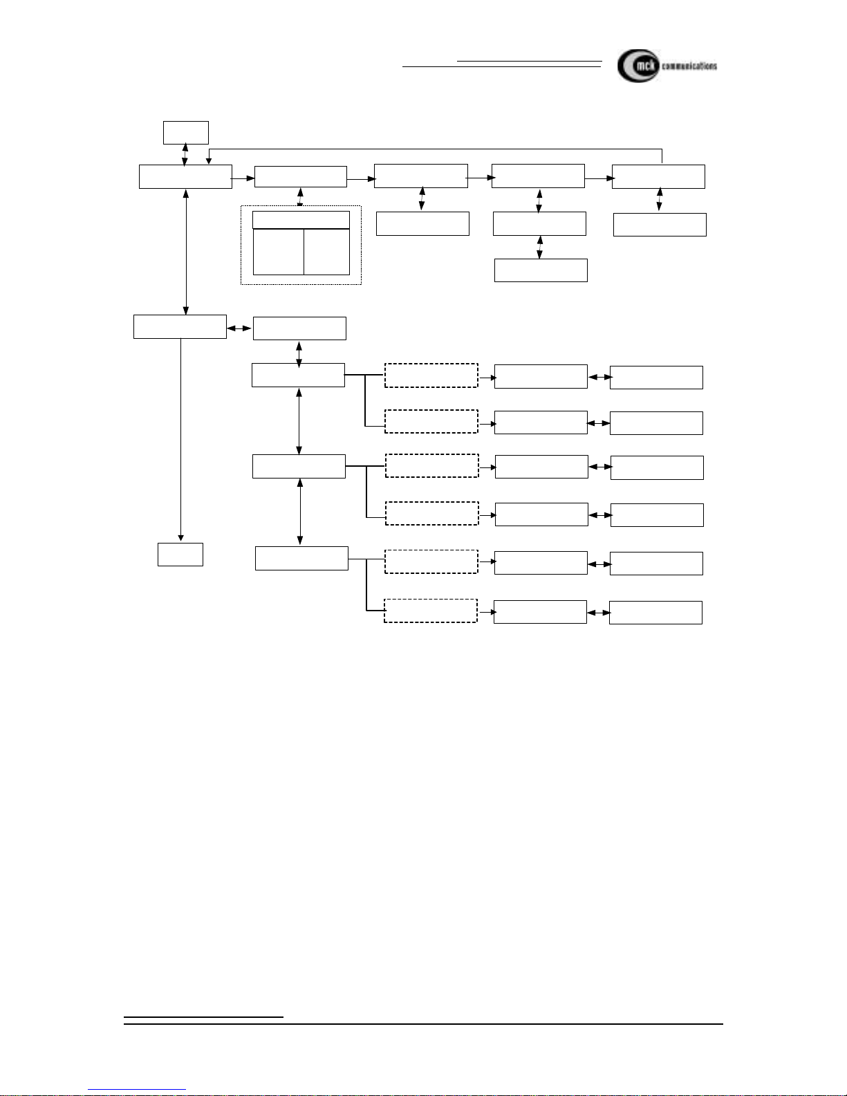
Figure 3: Definity EXTender 3000 Menu Flow Chart - Part 1
^Clear MSNs
Prev Ok Next
*Set TEI1
Prev Ok Next
Set TE1 Type
Prev Ok Next
Set Connect Rate
Prev Ok Next
Go Online
Ok Next
ISDN Setup Menu
Ok Next
A
Connecting (connects
to switch)
Clear MSNs: Yes
Prev Ok Next
Clear MSNs: No
Prev Ok Next
TE1 Type: Auto
Prev Ok Next
TE1 Type: Fixed
Prev Ok Next
Conn Rate: Auto
Prev Ok Next
Conn Rate: 56K
Prev Ok Next
* For U interfce Only
^ For S/T Interface Only
*Set Switch CO Type
Prev Ok Next
National ISDN (NI-1)
AT&T 5ESS,
NortelDMS-100
* Set SPID1
Prev Ok Next
* Set SPID2
Prev Ok Next
Drop/Redial to Accept
Drop/Redial to Accept
* Set DN1/
^ Set MSN1
Prev Ok Next
* Set DN1/
^ Set MSN1
Prev Ok Next
Drop/Redial to Accept
Drop/Redial to Accept
Prev
Next
Ok
Prev
Legend
Drop/Redial to Accept
*Set TEI2
Prev Ok Next
Drop/Redial to Accept

Page 18 EXTender 3000 Quic k In stallation Guide
Definity - EXTender 3000 Menu
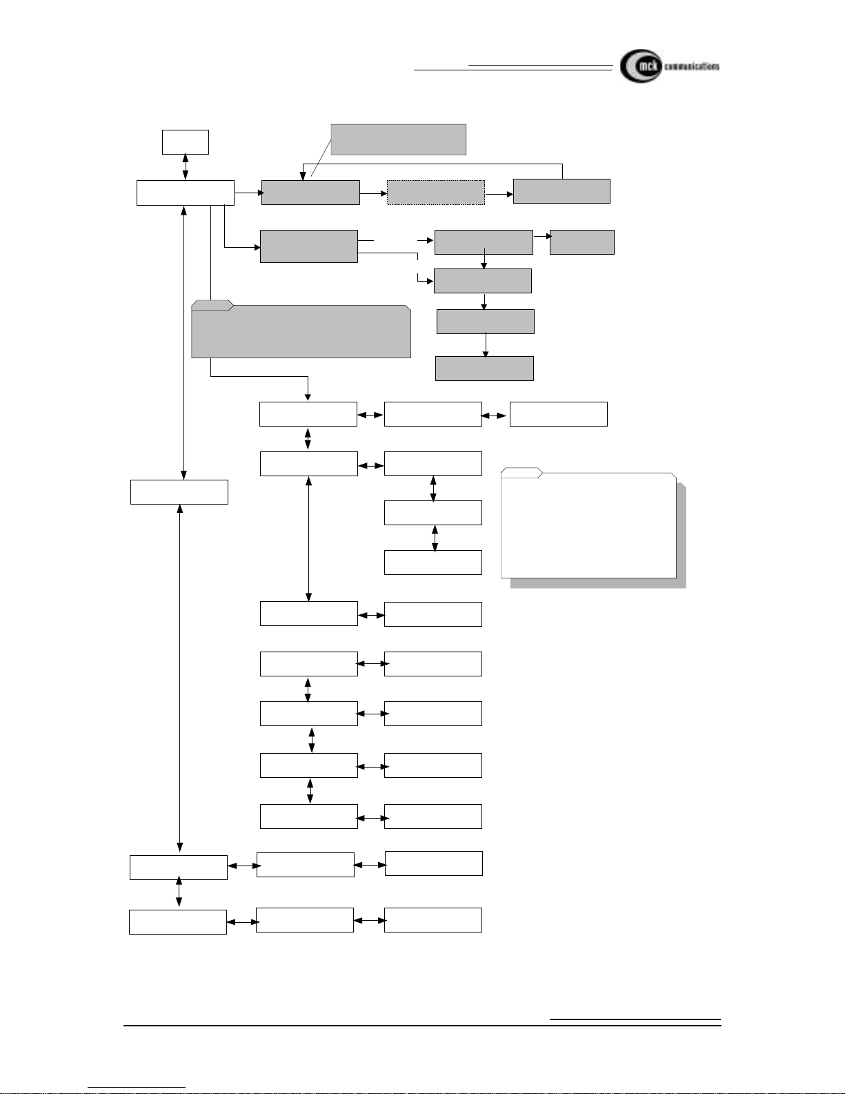
Figure 4: Definity EXTender 3000 Menu Flow Chart - Part 2
Set Office Number
Prev Ok Next
Set Remote Pho n e N umber
Prev Ok Next
Set Data Number
Prev Ok
Ethernet Data Only
If Disabl ed
If Enabled
Set COD Mode
Ring/Lamp/Voice
Prev Ok Next
Set Dial Numbers
Prev Ok Next
Set Dialback
Prev Ok Next
C
Drop/Re d i al to Accept
Drop/Re d i al to Accept
Drop/Re d i al to Accept
Enable Dialback
OK No
Disable Dialback
OK No
Moni to r Data: Yes
Prev Ok Next
A
Now Enabled
Now Di sabled
Set COD Parameters
Prev Ok Next
B
Set PPP Parameters
Prev O k Next
Ethernet Data Only
Set Bridge
Prev Ok Next
Ethernet Data Only
Set Call Timeout
Prev Ok Next
Drop/Redial to Accept
Set Connect T imeou t
Prev O k Next
Drop/Redial to Accept
Set Data Monitor
Prev Ok Next
Monitor D at a : No
Prev O k Next
A
This menu appears
for Serial Data type
only.
If disabled
Enable COD
Ok No
Now Enabled
If enabled
Disable COD
Ok No
Now Disabled
Set ACD Tone
Prev Ok Next

EXTender 3000 Quick Installation Guide
Definity - EXTender 3000 Menu Page 19
Figure 5: Definity EXTender 3000 Menu Flow Chart - Part 3
Data Rate: See Chart
Prev Ok Next
Set Remote COM Port
Prev Ok Next
Data Bits: 7
Prev Ok Nex t
A
Parity: None
Prev Ok Next
Stop Bits: N one
Prev Ok Next
Data Bits: 8
Prev Ok Next
Parity: Even
Prev Ok Next
Stop Bits: 2
Prev Ok Next
Data Rate Chart (kpbs)
2.4
4.8
9.6
115.2
19.2
38.4
57.6
Parity: Od d
Prev Ok Next
Set Voi ce Par ameter s
Prev Ok Next
If Disabled
Enable Silence Det.
Ok No
Now Enabled
If Enabled
Disable Sil ence Det.
Ok No
Now Disabled
Phone Compandin g
Prev Ok Nex t
If u-Law
Set A-L aw
Ok No
Now A-Law
If A-Law
Set u-La w
Ok No
Now u-Law
If u-Law
Set A-La w
Ok No
Now A-Law
If A-Law
Set u- Law
Ok No
Now u-Law
A
Pots Comp anding
Prev Ok Next
Set Silence Detect
Prev Ok Next
Set Voice Coder
Prev Ok Nex t

Page 20 EXTender 3000 Quic k In stallation Guide
Definity - EXTender 3000 Menu
Figure 6: Definity EXTender 3000 Menu Flow Chart - Part 4
Set Misc Parameters
Prev Ok Next
A
Code Acc ept ed
Set Feature Code
Prev Ok Next
Set Data Type
Prev Ok Next
Drop/Redial to Accept
Data Type : Se ri al
Prev Ok Next
Data Type : Dia l- u p
Prev Ok Next
Data Type: Ethernet
Prev Ok Next
Set User ID
Prev Ok
Drop/Redial to Accept
View Remote Stats
Prev Ok Next
Diagnostic Menu
Prev Ok Next
No Errors Found
Exit
View Office Stats
Prev Ok Next
No Errors Found
Exit
Reset Stats
Prev Ok Next
Stats Reset
View Office Data Type
Prev Ok
Office Data Type: Dial-
up, Seria l or Et her net
Remote x.xxxx.x.x
View Serial No
Prev Ok Next
Office xxxx
Remote x.xxxx.x.x
View S/W Version
Prev Ok
Office Vx.xxxx.x.x
Note: When you c ha nge the Data
Type the phone displays : Requires
Restart
OK No
If you select OK, the units are
reboot ed . I f y ou pr es s No, the data
type is not changed.
Set Logout Code
Drop/Redial to Accept

EXTender 3000 Quick Installation Guide
Definity - EXTender 3000 Menu Page 21
Figure 7: Definity EXTender 3000 Menu Flow Chart - Part 5
Set DOD Mode
Prev Ok Next
Set PPP Param eters
Prev Ok Next
B
DOD Mode: None, Tx
Only, Rx/T x, Tx /Rx
Local
Prev Ok Next
Set DOD Timeout
Prev Ok Next
Set Stac Compression
Prev Ok Next
Drop/Red ia l to Ac c ept
Compression: Enab le,
Disable
Prev Ok Next
Recv Auth: None,
PAP, CHAP
Prev Ok Next
Set Receive Auth
Prev Ok Next
Set Receive User
Name
Prev Ok Next
Receive User Name
Set Receive Password
Prev Ok Next
Receive Pa ssw ord
Set Sen d Auth
Prev Ok Next
Send Auth: None,
PAP, CHAP
Prev Ok Next
Set Sen d User Name
Prev Ok Next
Send User Name
Set Sen d Pass word
Prev Ok
Send Password
Set Bridge
Prev Ok Next
Set LA Timeou t
Prev Ok
Drop/Red ia l to Ac c ept
B
This menu appear s fo r
Ether ne t da t a t y pe
only.
This menu appear s fo r
Ethernet data type only.
Displayed only if STAC
card is in s ta lled

Page 22 EXTender 3000 Quic k In stallation Guide
Definity - Troubleshooting the Remote and Office Modules
Definity - Troubleshooting the Remote and Office Modules
The Troubleshooting section includes information for the Office Module and Remote Module, and aids in
troubleshooting efforts from either location.
There are a variety of reasons why errors may occur during transmission or connection. Whenever you
encounter a problem , there are some general areas you should check first:
• Ensure the AC power adap ter is connected to the Office and Remote Modules.
• Ensure all interconnecting cables and connections to wiring blocks are secure and properly seated.
• Ensure you are using the Remote Module at the remote site and the Office Module at the switch site.
• Ver ify the LEDs are fla shing.
• Eliminate potent ial causes of interference.
• Check the error message on the telephone.
• Verify the I SDN parameters and Dial Number s.
Table 4: Definity Troubleshooting the Remote and Switch
If... Then...
No Remote Site Phone Disp lay • Ensure you have a Remote Module, and not a Office Mod-
ule.
• Ensure the AC power adapter is connected to the Switch
and Remote Modules, and the LED is lit.
• Ensure the installation has not bee n moved, or any new wiring done.
No Office Module Connection • Ensure the correct dial numbers have been programmed
into the Remote Module. Refer to Setting the Dial Number
earlier in this guide.
• Ensure the AC power adapter is connected to the Office
Module and all interconnecting cables are properly seated.
• Ensure you have a Of fice Module at the office site, an d not
a Remote Module.
• Ensure your Remote & Office Modules have the correct
ISDN parameters
No indicator Lights at Power Up • Ensure the AC po wer a dap ter is co nnec te d to the EXTender
Module.
• Ensure the AC power out let is work ing. Che ck it wi th som e
other electrica l device.
• The module may not be operational
Office Module Will Not Answer • Someone in the office could be using the port, and is
unaware you are trying to conne ct. Wait for a short period,
then try to connect agai n.
• Ensure you entered the correct PBX dial number (your
Switch Module MSN1/DN1 number).
• Your Office Module’s DN1 may be entered incorrectly. If a
DN is inco r rec t, t h e I SDN line w i ll not rec ei ve a ca ll on t hat
DN.

EXTender 3000 Quick Installation Guide
Definity - Tr oubleshooting the Remote and Office Modules Page 23
Dialback Timeout • Ensure the Remote Module dial number has been set cor-
rectly in the ‘Set Dial Numbers’ phone menu.
Unit Does Not Wake Up From COD
Waiting When Receiving a Ca ll
• Ensure the Remote Module dial number has been set correctly in the ‘Set Dial Numbers’ phone menu.
• For more information on troubleshooting techniques consult the System Administrator’s Guide.
Table 4: Definity Troubleshooting the Remote and Switch
If... Then...

Page 24 EXTender 3000 Quic k In stallation Guide
Norstar/Meri dian - Installing the Office Module
Norstar/Meridian - Installing the Office Module
Pre-Installation Checklist
Ensure your EXTender Office Kit includes the following items:
• One EXTender 3000 Offic e Module
• One EXTender 3000 Office Module System Administrator Manual
• One EXTender 3000 Office Module Quick Installation Guide
• 12 volt DC u nregulated suppl ied by standard 1 20 volt adapter (U interface) or a 12 volt DC unregulated, supplied by 220/240v adapters (S/T interface)
• One ISDN line cord (RJ45 cable)
Ensure the maximum lengt h of your cab le bet ween the PBX and the Offic e Module do es not e xceed 500 fee t
(150 meters).
CAUTION: Do not connect a digital te lephone to an Office Modul e.
ISDN Line Checklist
The recommended ISDN line provisioning for your U or S/T interface ISDN line is:
• ISDN CO Switch type:
• U Interface: AT&T 5ESS, Nortel DMS100, or National ISDN NI-1
• S/T Interface: ETSI NET3
• Circuit Swit ched Voice and Data on both B channels (B1 and B2).
• No call features are re quired on any B channels.
• Must be capable of 56K or 64k Synchr onous Data Calls, Clear Cha nnel.
Note: Specifi cations are subject to change without notice as technological or manufacturing
changes warrant.
• Ensure you have the proper ISDN line installed at the Remote module’s site.
• Ensure you know the SPID/DN numbers (U interface), TEI type and Connect Rate (56K or 64K).
You obtain this information from your local ISDN serv ice provider when the ISDN lines are
installed. Note that the S/T Interfac e uses MSN (Multiple Subscriber Nu mber) num bers instead of
SPID or DN numbers
• Ensure that you have registered the ISDN lines with your long distance carrier for ISDN DATA
Service, if required .

EXTender 3000 Quick Installation Guide
Norstar/Mer idian - Installing the Off ice Module Page 25
Installation Procedure
All connections to the Office Module are done via the back panel.
Figure 8: Norstar/Meridian Office Module Back Panel
1. Connect the ISDN BRI li ne from your P BX or a c entral office (CO) li ne to the ISDN jack of the Office
Modul e at th e on- p r emise location. Us e th e R J 4 5 ca b le , in cl u d ed wi t h th e sys t em.
Ensure you connect an ISDN ST interface Office Module to ST interface line or an ISDN U interface
Office Module to U interface line. A quick way to check the ty pe of ISDN interface on your office module is to determi ne which way the line leads on your RJ45 cable are pointing if you were to insert the
cable into office module. The cable li ne leads point “up for U” (point down for ST). The U interface
connector is orientated the same as the digital port and Ethernet connectors.
2. Connect the Office Module SWITCH jack to the 2-wire di gital port on the P BX us ing a standard pho ne
cable.
3. If you are usi ng Ethe rnet da ta, c onnect the Et hernet jack o n the Of fic e Mod ule to t he Eth ernet j ack a t the
on-premise location. Use a standard Ethernet cable. Refer to the Data Configuration section of the Sys tem Administrator’s Guide to set the E thernet data type operation.
4. If you are us ing Serial o r Dial up data, connect the RS -232 jack on the Office Module to the on-premise
PC or Data Communications Server. Use a straight-through RS-232 cable. You may need an adapter if
your equipment does not have a 9-pin connector. Refer to the Data Configuration section of the System
Administrator’s Guide to set the Ethernet data type op er ation.
5. Connect the AC adapter to a n electrical outlet. Use onl y the AC adapters provided with t he E xtender . U
interface requires a 120v AC adapter, an S/T interface requires a 220/240v AC adapter.
6. The Office Module s tarts powering up. After a long series of flashing LED sequence s, the Office Module LED will bl ink a repeati ng se rie s of yell ow, green, *green, red. Thi s LED se quenc e confi rms that th e
Office Module is installed correctly.
*Note: For an S/T Interface, the third blink may not be green.
Ethernet
Jack
ISDN Jack
Electrical
Outlet
Switch Ethernet RS-232
ISDN +12VDC
RJ45 Digital Line
RJ45 Cable
Serial Cable
RJ45 Cable
AC Adapter
PBX or Key System
U Interface S/T Interface

Page 26 EXTender 3000 Quic k In stallation Guide
Norstar/Meri dian - Installing the Office Module
7. If applicable, administer the ISDN BRI and station ports as required.
• If the Office Module is connected to an ISDN BRI port on your PBX you should a dmi nister your
incoming PRI to route data calls that are des tined for th e Office Module.
• Administer the station port as you would any other digital port station.

EXTender 3000 Quick Installation Guide
Norstar/Meridian - Configuring the Office Module Page 27
Norstar/Meridian - Configuring the Office Module
Pre-Configuration Checklist
Ensure th a t th e install at io n pro c ed u r e fo r th e O ffice Modul e h as be en co mp l eted, and all cables are co nnected correctly. Please refer to Figure 1 for installation.
Configuration Procedure
The PC must be running a VT100 termin al emulation communication application. The Office Module can
run in one of the three Data types: Serial, Ethernet and Dial-u p (defa ult). For more information about these
data types, see the EXTender 3000 System Administrator’s Guide.
For U interface units you must program the SPID numbers and the numbers for your ISDN line. For S/T
interface you can configure the MSN numbers if required.
For basic operation of S/T interface units (no data) there is no need to change the defau lt settings programmed in the EXTender. Refer to the EXTender 3000 System Administrator’s Guide for di rec tions on
configuring the EXTender for data operation.
Accessing the Terminal Configuration Menu
For all data types:
1. To access the configura tion menu for the Office Module, you must connect a termina l or PC to the RS232 port of the Switch Module.
The PC must be running a terminal emulation package. Configure your terminal or terminal application
to 9600bps, No parity, 8 data bits, and 1 stop bit. The terminal type should be set to VT100.
2. Unplug the Office Module, and plug it back in after waiting a few seconds.
When the Office Modu le is powered up, a specifi c boot blin k sequen ce is obse rved, af ter approximate ly
60 sec. it will blink three sets of 8 yellow flashes.
3. Type the word MENU from your PC or terminal while the LED blinks its first set of 8 yellow flashes,
described above . T he Configuration menu will appe ar.
For dialup data type only:
If your Module’ s data typ e is Dial-up (th e factor y default data type) you ca n access te rminal confi gurati on at
any time from the AT command mode.
1. To access the configuration menu you must connect a terminal or PC to the RS-232 port of the Of fice
Module. The PC must be running a terminal emulation package with terminal type set to VT100.
2. Configure your PC COM port set tings to match the Offic e Module.The factory defa ult COM port settings for dial-up da ta types are: 57600 bp s, No parity, 8 data bits, and 1 stop bit. If t his has be en chan ged
set your PC to use the current settings or use the Power-up Access Method (optional).
From the AT command mode type AT@MENU followed by a RETURN key from your PC. The Configuration menu will appear .
For Ethernet data type only:
If your Module’s data type is Ethernet you can access terminal co nfiguration at any time from the Ethernet
Console.
Page 28 EXTender 3000 Quic k In stallation Guide
Norstar/Meridian - Configuring the Office Module
1. To access the configuration menu you must connect a terminal or PC to the RS-232 port of the Of fice
Module. The PC must be running a terminal emulation package with terminal type set to VT100.
2. Configure your PC COM port set tings to match your Office module.The factory def ault COM port settings, after power-up are: 57600 bps, No parity, 8 data bits, and 1 stop bit. I f this has been changed set
your PC to use the current settings or use the Power-up Access Method (optional).
From the Ethern et Console type MENU followed by a RETURN key from your PC. The Configu ration
menu will appear..
Table 5: Norstar/Meridia n Configuration Menu
Menu It em Funct ion
Show Settings Displays the current S w itch Module configur ation.
Configure ISDN Enter the ISDN parameters.
Configure System Modify passwords and upgrade the software.
Configure Data Select the data type and adjust the COM port
Configure Voice Modify the voice setti ngs

EXTender 3000 Quick Installation Guide
Norstar/Mer idian - Installing the Remote Module Page 29
Norstar/Meridian - Installing the Remote Module
Pre-Installation Checklist
Ensure your EXTender 3000 kit includes the following items:
• One EXTender Remote Module
• One EXTender 3000 Office Module Quick Installation Guide
• 12 volt DC u nregulated suppl ied by standard 1 20 volt adapter (U interface) or a 12 volt DC unregu-
lated, supplied by 220/240v adapter s (S/T interface)
• One ISDN line cord (RJ45 cable)
Ensure your digital telephone is loca ted within 400 feet (120 meters) of the EXTender Remote Module.
CAUTION: Do not connect a digital te lephone to an Office Modul e.
Installation Procedure
All connections to the Remote Module are done via the back panel.
Figure 9: N ors t ar/Meri dia n R emote Mo du l e Ba c k Pa nel
1. Connect the ISDN jack on the Remote Modul e to your ISDN jack using the RJ45 cable that comes with
the kit.
2. Connect the digital telephone to the PHONE jack of the Remote Module.
3. If you are using Etherne t data, connect the Eth ernet jack on the Remote Module to your local LAN or
PC. Refer to the Data Confi guration section of the Sy st em Admi nis trator’s Gui de to set the Ethernet
data type operation.
Ethernet
Jack
ISDN Jack
Electrical
Outlet
Phone Ethernet RS-232
ISDN +12VDC
RJ11 Digital Li ne
RJ45 Cable
Serial Cabl e
RJ45 Cable
AC Adapter
Analog
Port
Digital Pho ne
Telephone

Page 30 EXTender 3000 Quic k In stallation Guide
Norstar/Meri dian - Installing the Remote Module
4. If you are using Serial or Dial up data, connect the RS-232 jack on the Remote Module to your PC.
Use a straight-through RS-232 cable. You may need an ada pter if your PC does not have a 9-pin connec-
tor. Refer to the Data Configuration section of the System Administrator’s Guide to set the Ethernet
data type operation.
5. If you would like to use an ana log telephone, connect it to the Analog Device jac k o f the Remote Module.
6. Connect the AC adapter to an el ectrical outlet. Use only the AC adapters provided with the Remot e
Module.
7. The Remote Module starts powering up. After a series of flashing LED sequences, the display on the
digital telephone will initialize, and read Go Online. Once you’re at the Go Online prompt, the LED
sequences on th e Remote module should be yellow, green, *green, red.
*Note: For an S/T ISDN int er face, the third blink may not be Gr ee n.
Refer to the following sections in this document for instructions on configuring the Extenders for data operation.

EXTender 3000 Quick Installation Guide
Norstar/Meridian - Configurin g the R emote Module Page 31
Norstar/Meridian - Configuring the Remote Module
The Remote Module can be acc essed through the ETI or the digit al phone. The procedures that follow will
describe configuration using the digital phone to set up the Remote Module to be an extension to y our P BX/
Key System, which is the basic configuration.
For a full description of data configuration, see System Administrator’s Guide.
Pre-Configuration Checklist
Ensure that the installation pr ocedure has been completed, and all cables are connected correctly. Please
refer to Figure 9:. The phone must display the Go Online prompt.
Configuration Procedures
Configure the Remote Module by using the phone menus or by using the terminal configuration (as
described earlier in the ‘Configuring the Switch Module’ section). The digital telephone
configuration menu will allow you to easily navigate t hrough the set-up. Refer to the phone menu flow chart
in the next section when navigating the phone menus.
Your telephone will have either a 20 or a 40-character display, depending on your phone type. The menus
displayed with 20 cha r acters are, for the most part, abbreviated versions of the menus displayed with 40
characters. Examples of the different displays are in the table below.
Table 6: Norstar/Meridian Character Display
40 Character Display 20 Character Display
Set ISDN Parameters ISDN Setup Menu
Set Dial Numbers Set Dial No’s
Set COD Parameters Set COD Parms
Set PPP Parameters (for Eth erne t Dat Type only) Set PPP Parms (for Ethernet Dat Type only)
Set Bridge Parameters (for Ethernet Dat Type
only)
Set Bridge Parms (for Ethernet Dat Type only)
Set Remot e COM Port Set Rem COM Port
Set Misc Paramters Set Misc Parms
Set Voice Parameters Set Voice Parms
Diagnostic Menu Diagnostic Menu
View Serial Num b er View Serial No
View S/W Version View S/W Version
Refer to the phone menu flow chart in the next section when navigating the phone menus.

Page 32 EXTender 3000 Quic k In stallation Guide
Norstar/Meridian - Configuring the Remote Module
Configuration by Telephone
You use your digital telephone to configure the Remote Module by pressing the first three soft keys just
below the LC D display. The keys, in order from le ft to right, are: RLS (Accept), PRV (for PREVious), OK,
NEXT. U se the RLS key to accept the values you entered. The digital teleph one will display messag es that
will easily guide you through the various menus of the EXTender configuration procedure.
For U interface units you must program the SPID numbers and the numbers for your ISDN line. For S/T
interface you can configure the MSN numbers if required.
Note: S/T interf ace s uses a DN or MSN number. U interface uses SPID numbers.
1. From the Go Online menu press Next until you reach the Set ISDN Parameters menu. Press OK.
2. Program your ISDN CO Switch Type, SPID1 and SPID2 (U interface), DN1/MSN1 and DN2/MSN2
numbers, these para meters should be provi ded by your CO or PBX Syste m Administra tor. The TEI type
and ISDN Connect Rate are de fault to “Auto.”
3. Press PRV to return to the Set ISDN Parameters menu. If you have made any changes you will be
prompted to save them. Press OK to save.
4. Program the Switch Module phone number using the Set Dial Numbers menu on the digital telephone.
This is the Switch Module’s MSN, and will be used for the Remot e Module to Go Online, and connect
to the Sw i tc h Mo d ul e.
5. From Set ISDN Parameters menu press NEXT until you reach the Set Dial Numbers Menu. Press
OK.
6. Program the Office phone number from the Set Office Dial Numbers menu on the digital telephone.
This is the Office Module’s DN1/MSN1, and will be us ed for the Remote Module to Go Online, and
connect to the Office Module.
7. Program the Remote Module phone number from the Set Dial Numbers menu if you plan to use the
Remote Module Call On Demand (COD) or Dialback features.
8. From the Set Office Number menu press NEXT to advance to th e Set Remote Number menu.
The remote phone number should be set to the Remote Module’s DN/MSN line phone number. It
should be set exactly as needed for the Switch Modul e to reach the Remote Module. If your Switch
Modules are connecte d behind your P BX, do not forg et to begin the phone number wit h an external line
access code if applicable.
Call On Demand (COD) can reduce long distance line costs by establishing a con nec tion only when a
call is detec ted, or when there is activi ty on the remote phone. Dialback enables the Switch Module to
disconnect, and then dial back to the Remote Module after a connection has been successfully completed. This feature can reduce line charges incurred by your Remote Module. For more information on
configuration of dialback or COD, consult the Sys tem Administrator’s Guide.
Dialback en ables the Office Module to disconnect, and then dial bac k to the Remote Module after a connection has been successfully completed. This feature can reduce line charge s incurred by your Remot e
Module.
9. Set the remote number to the DN1/MSN1 number of the remote unit.

EXTender 3000 Quick Installation Guide
Norstar/Meridian - Configurin g the R emote Module Page 33
To Go Online
Connect your Remote Module to your Office Module:
1. Press PRV key until you return to the Go Online prompt, the press OK to ini ti ate the c on n e ction.
2. The Office phone number is dialed, and the modules connect. If passwords are e nabled then you will be
prompted for a password. Enter the password and press RLS key.
You are now connected to the PBX, and can use your remote phone as if your were in the office.
To go Offline (Disconnect)
Disconnect the Remote Module from the Office Module:
1. Access the Online Menu by pressing the press the HOLD key four times quickly when on-hook. The
Disconnect menu selection will appear.
2. To disconnect, press OK to initiate the disconnection.
3. To reconnect, first press NEXT and then OK.
4. To access addi t io nal Online menus press NEXT again.
If you encounter any error messages while operating the EXTender 3000s, please refer to the Error
Messages sect ion in Syst em Admini stra tor’ s Gui de T roubl eshoot ing s ectio n for a deta iled desc ription of
suggested actions to take.

Page 34 EXTender 3000 Quic k In stallation Guide
Norstar/Meridian - Configuring the Remote Module
LED Blink Sequences
Table 7: Norstar/Meridian Running EXTende r LED Indicator Sequences
Blink
No.
Description Status
1 Indicates the network connection
status
Red - not used (reserved)
Yellow - offline or COD waiting
Green - Online
2 Indicates the digital port stat us Red - signalling of fline, DSP OK
Yellow - DSP not responding
Green - Signalling online
3 Indicates the status of the I SDN Red - The IS D N is in activ e ( n etwork not detected)
Yellow - The ISDN is offline (network detect ed, not
synchronized)
Green - online
NOTE: When an S/T ISDN Interface is used, the LED
may not change color until the connection to the
Remote Module has been made. After connecting to
the Remote Module, the LED turns green.
4 Indicates th e 2nd B cha nnel status
call.
Red - Data Offline/no ana log (2nd B channel not in
use)
Yellow - Data/POTS Connec ting (2nd B channel
connecting)
Green - Data Online / Analog cal l active (2nd B channel connected)

EXTender 3000 Quick Installation Guide
Norstar/Mer idian - EXTender 3000 Menu Page 35
Norstar/Meridian - EXTender 3000 Menu
Remote Module System Flowchart
Use the three fun ction keys, located just below the L CD dis play , and the Release button to navigate through
the menus and accept parameters.
Figure 10: Norstar/Me ridian EXTender 3000 Menu Flow Chart - Part 1
^Clear MSNs
Prev Ok Next
*Set TEI1
Prev Ok Next
Set TE1 Type
Prev Ok Next
Set Connect Rate
Prev Ok Next
Go Online
Ok Next
ISDN Setup Menu
Ok Next
A
Connecting (connects
to switch)
Clear MSNs: Yes
Prev Ok Next
Clear MSNs: No
Prev Ok Next
TE1 Type: Auto
Prev Ok Next
TE1 Type: Fixed
Prev Ok Next
Conn Rate: Auto
Prev Ok Next
Conn Rate: 56K
Prev Ok Next
* For U interfce Only
^ For S/T Interface Only
*Set Switch CO Type
Prev Ok Next
National ISDN (NI-1)
AT&T 5ESS,
NortelDMS-100
* Set SPID1
Prev Ok Next
* Set SPID2
Prev Ok Next
RLS to Accept
RLS to Accept
* Set DN1/
^ Set MSN1
Prev Ok Next
* Set DN1/
^ Set MSN1
Prev Ok Next
RLS to Accept
RLS to Accept
Prev
Next
Ok
Prev
Legend
RLS to Accept
*Set TEI2
Prev Ok Next
RLS to Accept

Page 36 EXTender 3000 Quic k In stallation Guide
Norstar/Meridian - EXTender 3000 Menu
Figure 11: Norstar/Meridian EXTender 3000 Menu Flow Chart - Part 2
Set Office Numb er
Prev Ok N ex t
Set remote Ph one Num ber
Prev Ok Next
Set Data Number
Prev Ok
Ethernet Data Only
If Disabled
If Enabled
Set COD Mode
Meridian: Di sabl e/ Ri ng/ Lam p
Norstar: Disable/Ring
Prev Ok Next
Set Dial Numbers
Prev Ok Next
Set Dialback
Prev Ok Next
C
Cancel Ok Bksp (Nor st ar 2
line display only)
RLS to Accep t
Cancel Ok Bksp (Nor st ar 2
line display only)
RLS to Accep t
Cancel Ok Bksp (Nor st ar 2
line display only)
RLS to Accep t
Enable Dialback
OK No
Disable Dialback
OK No
Monitor Data: Yes
Prev Ok Next
A
Now Enabled
Now Disabled
Set COD Parameters
Prev Ok Next
B
Set PPP Parameters
Prev Ok Next
Ethernet Data Only
Set Bridge
Prev Ok Next
Ethernet Data Only
Set Call Timeout
Prev Ok N ex t
Cancel Ok Bksp (Norstar 2
line display only)
RLS to Accept
Set Connect Ti m eout
Prev Ok Next
Cancel Ok Bksp (Norstar
2 line display only)
RLS to Accept
Set Data Monitor
Prev Ok Next
Monitor Data: No
Prev Ok N ex t
A
This menu appears
for Serial Data type
only.
If disabled
Enable COD
Ok No
Now Enabled
If enabled
Disable COD
Ok No
Now Disabled
Set Hold Timeout
Prev Ok N ex t
Set ACDTone
(Meridian Only)
Prev Ok N ex t
EXTender 3000 Quick Installation Guide
Norstar/Mer idian - EXTender 3000 Menu Page 37
Figure 12: Norstar/Me ridian EXTender 3000 Menu Flow Chart - Part 3
Data Rate: See Chart
Prev Ok Next
Set Remote COM Port
Prev Ok Nex t
Data Bits: 7
Prev Ok N ext
A
Parity: None
Prev Ok N ext
Stop B its: None
Prev Ok Nex t
Data Bits: 8
Prev Ok Next
Parity : Even
Prev Ok Next
Stop Bits: 2
Prev Ok Next
Data Rate Chart (kpbs)
2.4
4.8
9.6
115.2
19.2
38.4
57.6
Parity: Odd
Prev Ok Next
Set Voice Paramet er s
Prev Ok Next
If Disabled
Enable Si l en c e Det .
Ok No
Now Enabled
If Enabled
Disable Silence Det.
Ok No
Now Disabled
Phone Compandi ng
Prev Ok Next
If u-Law
Set A-Law
Ok No
Now A-Law
If A-Law
Set u-La w
Ok No
Now u-Law
If u-Law
Set A-Law
Ok No
Now A-Law
If A-Law
Set u-Law
Ok No
Now u-Law
A
Pots Companding
Prev Ok N ext
Set Sile nc e Det ect
Prev Ok N ext
Set Voic e C oder
Prev Ok Next
Page 38 EXTender 3000 Quic k In stallation Guide
Norstar/Meridian - EXTender 3000 Menu
Figure 13: Norstar/Me ridian EXTender 3000 Menu Flow Chart - Part 4
Set Misc Parameters
Prev Ok Next
A
Code Accepted
Set Featur e C ode
Prev Ok Next
Set Data Type
Prev Ok N ext
Cancel Ok Bksp
Data Type: Serial
Prev Ok Next
Data Type: Dial-up
Prev Ok Next
Data Type: Ethernet
Prev Ok Next
Set User ID
Prev Ok
Cancel Ok Bksp
View Remote Stats
Prev Ok N ext
Diagnost ic Menu
Prev Ok Next
No Errors Found
Exit
View Office Stats
Prev Ok N ext
No Errors Found
Exit
Reset Stats
Prev Ok N ext
Stats Reset
View Office Data Type
Prev Ok
Office Data Type: Dial-
up, Serial or Ethernet
Remote x.xxxx.x.x
View Serial No
Prev Ok Next
Office xxxx
Remote x.xxxx.x.x
View S/W Version
Prev Ok
Office Vx.xxxx.x.x
Note: When you change the Data Type
the phone displays : Requi res Restart"
OK No
If you select OK, the untis ar e rebooted.
If you pre ss No, the data ty pe i s not
changed
Change MS B Key
Prev Ok N e xt
Select Key
Shaded boxes indicate
Meridian Only
RLS to Accept
Auto-Detect Phone
Type
If Enbaled
If Disabled
Set Meridian Phone
Type
Set Norstar Phone
Type
Meridian S et
Enable Auto Detect
Auto-Detect Set
Norstar 2 l ine display: Can cel OK Backspace
Meridi an : RLS to Accept

EXTender 3000 Quick Installation Guide
Norstar/Mer idian - EXTender 3000 Menu Page 39
Figure 14: Norstar/Me ridian EXTender 3000 Menu Flow Chart - Part 5
Set DOD Mode
Prev Ok Next
Set PPP Parameters
Prev Ok Next
B
DOD Mode: None, Tx
Only, Rx/Tx, Tx/Rx
Local
Prev Ok Next
Set DOD Time o u t
Prev Ok Next
Set Stac Compression
Prev Ok Next
Cancel Ok Bksp
Compression: Enable,
Disable
Prev Ok Next
Recv A uth: None,
PAP, CHAP
Prev Ok Next
Set Receive Auth
Prev Ok Next
Set Receive User
Name
Prev Ok Next
Receive User Name
Set Receive Password
Prev Ok Next
Receive Password
Set Send Auth
Prev Ok Next
Send Auth: None,
PAP, CHAP
Prev Ok Next
Set Send User Name
Prev Ok Next
Send User Name
Set Send Password
Prev Ok
Send Password
Set Bridge
Prev Ok Next
Set LA Timeout
Prev Ok
Cancel Ok Bksp
B
This me nu appears f or
Ethernet data ty pe
only.
This m enu appears for
Ethernet data type only.
Displayed only if STAC
card is installed
Norstar 2 line display: Cancel OK Backspace
Meridian: RLS to Accept

Page 40 EXTender 3000 Quic k In stallation Guide
Norstar/Meridian - Troubleshooting the Remote and Office Modules
Norstar/Meridian - Troubleshooting the Remote and Office Modules
The Troubleshooting section includes information for the Office Module and Remote Module, and aids in
troubleshooting efforts from either location.
There are a variety of reasons why errors may occur during transmission or connection. Whenever you
encounter a problem , there are some general areas you should check first:
• Ensure the AC power adap ter is connected to the Office and Remote Modules.
• Ensure all interconnecting cables and connections to wiring blocks are secure and properly seated.
• Ensure you are using the Remote Module at the remote site and the Office Module at the switch site.
• Ver ify the LEDs are fla shing.
• Eliminate potent ial causes of interference.
• Check the error message on the telephone.
• Verify the I SDN parameters and Dial Number s.
Table 8: Norstar/Meridian Troubleshooting the Remote and Switch
If... Then...
No Remote Site Phone Disp lay • Ensure you have a Remote Module and not a Office Mod-
ule.
• Ensure the AC power a dapter is co nnecte d to the EXTender
Remote and the L ED is lit. En sure the phone is functioning
correctly.
• Ensure the installation has not been moved or any new wiring done.
No Office Module Connection • Ensure the correct dial numbers have been programmed
into the Remote Module. Refer to Setting the Dial Number
earlier in this guide.
• Ensure the AC power adapter is connected to the Office
Module and all interconnecting cables are properly seated.
• Ensure you have a Of fice Module at the office site, an d not
a Remote Module.
• Ensure your Remote & Office Modules have the correct
ISDN parameters.
No indicator Lights at Power Up • Ensure the AC po wer a dap ter is co nnec te d to the EXTender
Module.
• Ensure the AC power out let is work ing. Che ck it wi th som e
other electrica l device.
• The module may not be operat ional (se e LED sequenc es on
next page).

EXTender 3000 Quick Installation Guide
Norstar/Meridian - Troubleshooting the Remote and Offic e Modules Page 41
Office Module Will Not Answer • Someone in the office could be using the port and is
unaware you are trying to conne ct. Wait for a short period,
then try connecting again.
• Ensure you entered the correct Office Phone Number (your
Office Module DN1 number).
• Your Office Module’s DN1 may be entered incorrectly. If a
DN is inco r rec t, t h e I SDN line w i ll not rec ei ve a ca ll on t hat
DN.
Dialback Timeout • Ensure the Remote Module dial number has been set cor-
rectly in the ‘Set Dial Numbers’ phone menu.
Unit Does Not Wake Up From COD
Waiting When Receiving a Ca ll
• Ensure the Remote Module dial number has been set correctly in the ‘Set Dial Numbers’ phone menu.
• For more information on troubleshooting techniques consult the System Administrator’s Guide.
Table 8: Norstar/Meridian Troubleshooting the Remote and Switch
If... Then...

Page 42 EXTender 3000 Quic k In stallation Guide
 Loading...