

MCI ELECTRONICS
www.olimex.cl
Luis Thayer Ojeda 0115. Of. 402 ▪ Santiago, Chile ▪ Tel. +56 2 3339579 ▪ info@olimex.cl
Arduino 4-20 mA + RTC Shield
User’s Manual
Rev. A
MCI-MA-0088

MCI Ltda.
Luis Thayer Ojeda 0115. Of 402
Santiago, Chile
www.olimex.cl
Tel: +56 2 3339579
Fax: +56 2 3350589
® MCI Ltda. 2011
Attention: Any changes and modifications done to the device will void its warranty unless
expressly authorized by MCI.
Manual Code: MCI – MA - 0088

Arduino 4-20 mA + RTC Shield User’s Manual
Page 3 of 10
Luis Thayer Ojeda 0115 Of. 402 ▪ Santiago, Chile ▪ Tel. +56 2 3339579 ▪ info@olimex.cl
www.olimex.cl
CONTENTS
1 INTRODUCTION ............................................................................................ 4
2 FEATURES .................................................................................................... 5
3 4-20mA SUPPORTED TRANSMITTERS ....................................................... 5
3.1 Type 2 ............................................................................................................ 5
3.2 Type 3 ............................................................................................................ 6
3.3 Type 4 ............................................................................................................ 6
4 SHIELD PARTS .............................................................................................. 7
5 SHIELD INSTALLATION ................................................................................ 8
6 PORT MAPPING .......................................................................................... 10
7 ELECTRICAL CHARACTERISTICS ............................................................. 10
8 MECHANICAL CHARACTERISTICS ............................................................ 10
9 DOCUMENT HISTORY ................................ ................................................ 10

Arduino 4-20 mA + RTC Shield User’s Manual
Page 4 of 10
Luis Thayer Ojeda 0115 Of. 402 ▪ Santiago, Chile ▪ Tel. +56 2 3339579 ▪ info@olimex.cl
www.olimex.cl
1 INTRODUCTION
The Arduino 4-20mA + RTC is a 4-20mA current signal adaptation board. This
Shield has 4 input channels which allow converting signals that come with this
industrial standard.
The Arduino 4-20mA + RTC has a DS1307 Real Time Clock which enables you to
add a time stamp to every converted data. The Real Time Clock has a backup power
supply, using a 12mm Coin type battery.
This Shield works with type 2, 3 and 4 current transmitters, and it can be connected
to Duemilanove, Mega and Uno platforms. To work with the Arduino 4-20 mA + RTC
Shield you need to connect an external 9-12 VDC power supply for its correct
operation.
With this board you can connect to any industrial sensor, monitor and even control
a variable directly from your Arduino board!

Arduino 4-20 mA + RTC Shield User’s Manual
Page 5 of 10
Luis Thayer Ojeda 0115 Of. 402 ▪ Santiago, Chile ▪ Tel. +56 2 3339579 ▪ info@olimex.cl
www.olimex.cl
2 FEATURES
4 4-20mA input channels.
12mm Coin type battery socket.
Real Time Clock.
o IC DS1307.
o 32kHz clock.
Arduino reset button.
4-20mA standards supported.
o Type 2.
o Type 3.
o Type 4.
9-12 VDC power supply.
4 Jumpers for type 3 transmitters.
Power supply connector for sensors.
3 4-20mA SUPPORTED TRANSMITTERS
The Arduino 4-20mA + RTC Shield supports transmitters which work with type 2, 3
and 4 current loops.
3.1 Type 2
Type 2 transmitters are energized by the current loop, where the supply voltage is
included in the receptor. The transmitter is floating and the ground is in the receptor.
Fig. 1: Type 2 transmitter connection schematic.

Arduino 4-20 mA + RTC Shield User’s Manual
Page 6 of 10
Luis Thayer Ojeda 0115 Of. 402 ▪ Santiago, Chile ▪ Tel. +56 2 3339579 ▪ info@olimex.cl
www.olimex.cl
3.2 Type 3
Type 3 transmitters have 3 wires powered by the source voltage in them. In this
case the transmitter is the power source for the current loop. The transmitter common
is connected to the common of the receptor.
Fig. 2: Type 3 transmitter connection schematic.
3.3 Type 4
Type 4 transmitters have 4 wires powered by the source voltage in them. The
transmitter powers the current loop and the receptor acts a floating load.
Fig. 3: Type 4 transmitter connection schematic.

Arduino 4-20 mA + RTC Shield User’s Manual
Page 7 of 10
Luis Thayer Ojeda 0115 Of. 402 ▪ Santiago, Chile ▪ Tel. +56 2 3339579 ▪ info@olimex.cl
www.olimex.cl
Battery Socket
Arduino Reset
Channel 1
Channel 2
Channel 3
Channel 4
V OUT
V IN
W3
W4
W1
W2
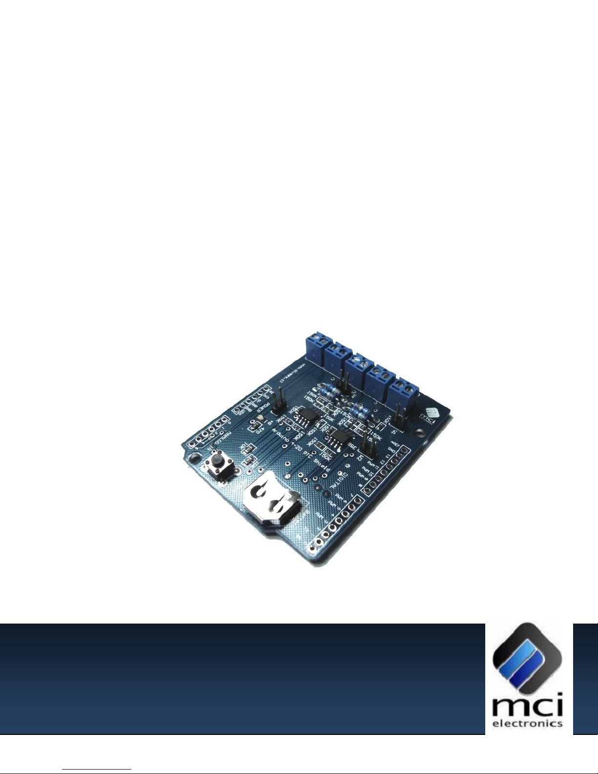
4 SHIELD PARTS
Fig.1: Arduino 4-20mA + RTC Shield top view.
Channel 1 – Channel 4: 4-20mA current signal inputs.
W1-W3: Loop type selection jumpers.
V OUT: Auxiliary power supply output for sensors.
V IN: External power LED indicator.
Battery Socket: 12mm Coin type battery socket.
Arduino Reset: Arduino board reset button.

Arduino 4-20 mA + RTC Shield User’s Manual
Page 8 of 10
Luis Thayer Ojeda 0115 Of. 402 ▪ Santiago, Chile ▪ Tel. +56 2 3339579 ▪ info@olimex.cl
www.olimex.cl
5 SHIELD INSTALLATION
Before starting to work with the Arduino 4-20mA + RTC Shield, the following
installation procedure must be done:
A. Position the Shield as shown in figure 3.
a. Note that the pin headers that connect the Shield to the Arduino
have only one position.
B. Connect the Shield to the Arduino main board.
C. Connect the Jumpers depending on the transmitter type.
a. For type 3 transmitters connect Jumpers W1-W4 depending on the
channels to be connected.
b. For type 2 and 3 transmitters disconnect the Jumpers W1-W4
depending on the channels to be connected.
D. Connect the 4-20mA current signal to the desired channel.
E. If required, connect the sensor supply voltage to the V OUT terminal.
F. Connect the Arduino main board to the PC using the USB cable.
G. Connect the Arduino main board 9-12 [VDC] 600mA power supply.
H. Run the test Sketch available on the website.

Arduino 4-20 mA + RTC Shield User’s Manual
Page 9 of 10
Luis Thayer Ojeda 0115 Of. 402 ▪ Santiago, Chile ▪ Tel. +56 2 3339579 ▪ info@olimex.cl
www.olimex.cl
A
B
C
D
E
Fig. 3: Arduino 4-20 mA + RTC Shield assembly.
Using a 12mm Coin type battery (MCI-PRT-00677) is recommended to maintain
the time configuration on the Real Time Clock embedded with the Arduino 4-20 mA +
RTC Shield in case of a power supply fault.

Arduino 4-20 mA + RTC Shield User’s Manual
Page 10 of 10
Luis Thayer Ojeda 0115 Of. 402 ▪ Santiago, Chile ▪ Tel. +56 2 3339579 ▪ info@olimex.cl
www.olimex.cl
Pin
Name
Function
ANALOG 0
AN1
Channel 1 analog input
ANALOG 1
AN2
Channel 2 analog input
ANALOG 2
AN3
Channel 3 analog input
ANALOG 3
AN4
Channel 4 analog input
ANALOG 4/SDA
SDA
SDA signal for communication with Real Time
Clock
ANALOG 5/SCL
SCL
SCL signal for communication with Real Time
Clock
RESET
RESET_ARD
Arduino board reset
Revision
Date
Edited by
Description/Changes
1.0
January 31, 2011
E. Martin
Initial document version
6 PORT MAPPING
The I/O ports used by the Arduino 4-20mA + RTC Shield cannot be used by
another shield, with the exception of SDA, SCL and RESET signals.
7 ELECTRICAL CHARACTERISTICS
9-12 VDC power supply.
100mA maximum current. (not considering transmitters power consumption)
8 MECHANICAL CHARACTERISTICS
Dimensions (WidthxLengthxHeight) 54x69x11 [mm]
9 DOCUMENT HISTORY
 Loading...