

MCi JH-400B, JH-428VU, JH-428LM, JH-440VU, JH-440LM Technical Manual
L
I
;___
I
~
TECHNICAL MANUAL
JH-4008
'·
SERIES CONSOLE
/r
.
\1
'\
. '
I !
,..,
·J
PRINTED
January 1 , 1978
MCI, INC.
4007
N.E.
6th
AVENUE
FORT LAUDERDALE,
FLORIDA 33334 USA
TELEPHONE: (305) 566-2853
TELEX: 514
362
MCI FTL

'~
I
'--
-~
I
1...-
I
'
~
INTRODUCTION
This
SERVICE
information
Series
of
JH-400B
material
quickly
technical
No
discussion
since
such
contribute
The
sectional
(All
MCI
manuals
AND
REPAIR
needed
to
Console.
is
as
simple
and
accurately
background.
of
design
information--although
to
the
purpose
tabs
are
allow
organized
manual
correctly
The
as
possible,
understood
problems
of
quick
in
this
supplies
operate
language
by
or
solutions
interesting--does
this
manual.
location
same
all
and
and
designed
anyone
of
way.)
of
maintain
the
presentation
with
is
all
the
to
be
a
included,
not
sections.
a
Note
that
explanation
circuits
REPAIR
should
studied
the
OPERATION
of
are
covered
be
carefully.
section
the
THEORY
in
attempted~until
OF
detail.
OPERATION.
gives
NO
this
a
tffiiNTENANCE
section
simplified
ALL
unusual
has
or
been
Page
1-2
JH-400B
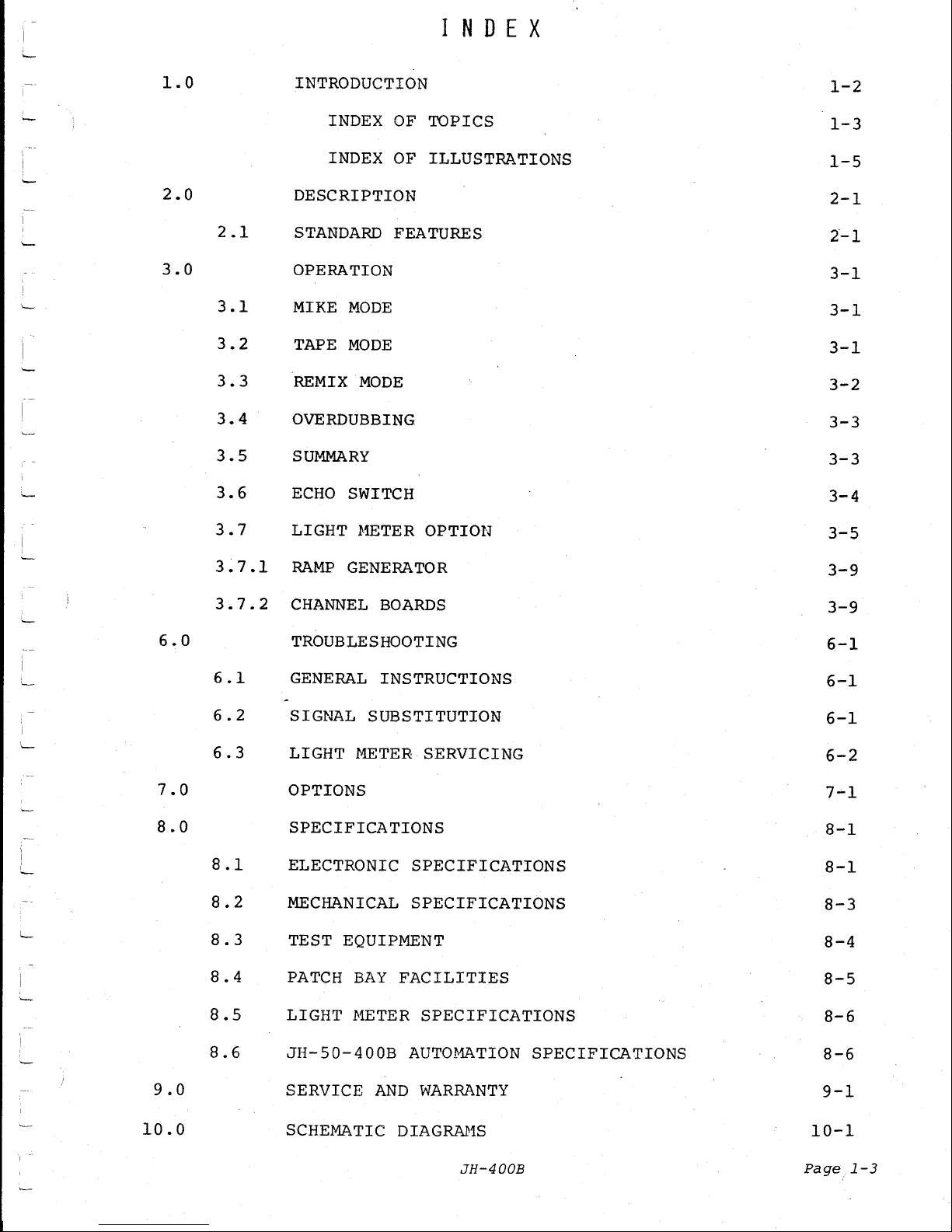
I N D E X
1.0
2.0
3.0
INTRODUCTION
DESCRIPTION
2.1
STANDARD
OPERATION
3.1
3.2
3.3
3.4
3.
5
3.6
3.
7 LIGHT
MIKE
TAPE
REMIX
OVERDUBBING
SU1-1MARY
ECHO
INDEX OF
TOPICS
INDEX OF ILLUSTRATIONS
FEATURES
MODE
MODE
MODE
SWITCH
~1ETER
OPTION
1-2
1-3
1-5
2-1
2-1
3-1
3-1
3-1
3-2
3-3
3-3
3-4
3-5
6.0
7.0
8.0
3~7.1
3.7.2
6.1
6.2
6.3
8.1
8.2
8.3
8.4
8.5
RA~W
CHANNEL
GENERATOR
BOARDS
TROUBLESHOOTING
GENERAL
INSTRUCTIONS
SIGNAL SUBSTITUTION
LIGHT
~lliTER
SERVICING
OPTIONS
SPECIFICATIONS
ELECTRONIC
MECHANICAL
SPECIFICATIONS
SPECIFICATIONS
TEST EQUIPMENT
PATCH
LIGHT METER
BAY
FACILITIES
SPECIFICATIONS
3-9
3-9
6-1
6-1
6-1
6-2
7--1
8-1
8-1
8-3
8-4
8-5
8-6
8.6
9.0
10.0
JH-50-400B
SERVICE
SCHEMATIC DIAGRAHS
AUTO~~TION
AND
WARRANTY
JH-400B
SPECIFICATIONS
8-6
9-1
10-1
Page
1-3
11.0
13.0
Page
1-4
13.1
13.2
SPARE
PARTS
LISTS
11-1
INSTALLATION
13-1
PUNCH
BLOCK
CONNECTIONS
13-1
GROUND
RULES
FOR
GROUNDING A RECORDING
SYSTEH
13-1A
JH-400B
I
I N D E X
OF
I L L U S T R A T I 0 N S
'--
FIGURE
TITLE
PAGE
1-10
NOT
USED
'--
11
ECHO
SWITCH--BLOCK
DIAGRAM
PRODUCING
FEEDBACK
LOOP
3-4
12
ECHO
SWITCH--BLOCK
DIAGRAM
PRODUCING
NO
FEEDBACK
LOOP
3-5
'~
13
JH-400B
LIGHT
METER
BLOCK
DIAGRAM
3-10
14
JH-400B
FLOW
CHART
3-7
15
MOTHER
BOARD
LOCATION
CHART
6-3
16-19
NOT
USED
20-32
SCHEMATICS
INDEX
10-1
JH-400B
Page
1-5

i
'--
DESCRIPTION
I
---
2.0
DESCRIPTION
The
JH-400B
Series
Console
is
an
IN-LINE
console
with
all
of
the
circuits
needed
for
one
complete
MIKE
CHANNEL
and
one
complete
REMIX
CHANNEL
in
each
I/O
module.
Therefore
the
number
of
input/
output
channels
is
completely
flexible.
Any
number
of
I/0
modules--
up
to
the
maximum
for
each
frame--may
be
operated
in
any
console.
If
additional
channels
are
needed,
they
may
be
added
by
simply
plugging
in
new
I/0
modules.
A
proprietary
Op-Amp,
custom
designed
for
optimum
Audio
performance
is
used
throughout
the
console.
In
critical
stages
this
Op~Amp
drives
a
complementary
pair
of
transistors
in
an
output
configur-
ation
which
produces
a
complete
Audio
amplifier
with
very
low
impedance,
low
distortion,
unusually
good
transient
response
and
high
drive
capability.
This
proprietary
Op-Arnp
allows
all
of
the
internal
circuits
in
the
JH-400B
consoles
to
operate
at
OdBv
instead
of
the
usual
-6dBv.
Its
larger
voltage
swing
allows
more
headroom
than
most
consoles
in
spite
of
the
higher
program
level.
With
a
program
level
6db
above
the
usual
level,
the
signal-to-noise
ratio
is
improved
and
the
RF
rejection
on
all
summing
buses
is
improved
by
6db.
The
JH-400B
Series
Consoles
are
supplied
in
two
frame
sizes--
the
JH-428B
and
the
JH-440B.
(Dimensions
are
shown
in
the
Specification
Section.)
The
JH-428B
is
wired
and
tested
for
up
to
28
IiJPUT/OUTPUT
(I/0)
modules
with
five
Console
Control
modules:
1.
A
C01'11'1UNICATION
module.
2.
A
MASTER
module.
3.
A
CONTROL
ROG.r-1
HONITOR
module.
4.
A STUDIO
MONITOR
module.
5:
A STATUS
module.
The
JH-440B
Console
is
wired
and
tested
for
up
to
40
I/0
modules
with
the
same
complement
of
Console
Control
modules.
2.1
STAimARD
FEATURES
Standard
features
for
all
JH-400B
Series
Consoles
include:
1.
Twenty-four
output
buses
are
provided.
2.
Five
Echo
Return
circuits
are
provided.
Four
of
these
circuits
have
full
quad
panning,
and
the
fifth
has
full
channel
assignment
capabilities.
3.
Three
Console
Programming
buttons
are
provided,
which
switch
all
I/0
modules
into
BIKE
mode,
TAPE
mode,
or
REMIX
mode.
JH-400B
Page
2-1
4.
REMIX
mode
outputs
include:
QUAD
~UX
2-MIX
derived
from
the
QUAD
MIX
MONO
~ux
derived
from
the
QUAD
MIX
Two
ECHO
SENDS
Two
CUE
SENDS
All
of
the
above
outputs
are
available
simultaneously.
5.
"Variable
Q"
EQ
circuits
on
each
I/0
module.
The
center
frequencies
of
the
filters
and
the
rolloff
points
of
Shelf
circuits
are
musically
related
to
each
other.
A
sufficient
number
of
switch
points
is
provided
to
allow
selection
of
the
exact
amount
of
EQ
required.
Switches
used
for
all
circuits
allow
EXACT
reproduction
of
any
EQ
previously
used.
6.
The
JH-400B
Consoles
are
iJOT
Automation-ready,
since
they
do
not
have
the
VCAs
incorporated
into
the
basic
design.
However,
they
have
been
mechanically
designed
for
easy
installation
of
the
necessary
Fader
Packages.
Automation
is
easy
to
install.
For a description
of
the
optional
equipment
available
on
these
Consoles,
see
the
section
on
OPTIONS.
Page
2-2
JH-400B

'
'
'
~
~
OPERATION
---
3.0
OPERATION
I
'-
The
quickest
way
to
become
familiar
with
the
operation
of
the
JH-400B
Series
Console
is
to
study
the
FLOW
CHART
on
page
3-7.
This
chart
shows
the
FUNCTIONS
performed
in
each
module,
and
their
relationship
to
each
other.
Switching,
interconnections,
etc.
are
shown
in
simplified
form.
Functions
ONLY
are
shown.
Programming
controls
for
THREE
MODES
OF
OPERATION
are
supplied
on
the
STATUS
module.
When
these
buttons
are
pressed,
all
I/O
modules
are
switched
into
one
of
the
three
modes.
To
understand
the
three
modes,
it
is
necessary
to
follow
the
signal
flow
when
the
appropriate
relays
are
activated.
3.1 MIKE
f'.10DE
1
'-
Neither
HONITOR
relays
nor
REtUX
relays
are
activated
for
this
mode.
From
the
~UKE
input,
the
signal
flows
through
the
Mike
preamp
to
the
CHANNEL
FADER,
then
through
the
EQ
circuits.
The
CHANNEL
BUS
assignment
switches
come
next.
(Including
the
direct
assign
switch
and
a
feed
to
the
ECHO
switch.)
Each
I/0
module
contains
ONE
CHANNEL
ACN
which
is
the
outout
amplifier
for
the
CH.&~NEL
BUS
having
the
same
number
as
the
I/0
module.
In
addition
to
feeding
the
TAPE
MACHINE
OUTPUT,
this
amplifier
also
feeds
the
~10NITOR
circuits.
(Through
the
MONITOR
relay
contacts.)
The
MONITOR
amplifiers
distribute
the
signal
to
the
CUE
SENDS,
the
ECHO
SENDS,
and
the
QUAD
MIX
BUSES
(via
the
PANNING
controls).
In
this
mode~
the
meters
read
the
output
of
the
CHANNEL
ACN
(which
is
the
TAPE
MACHINE
INPUT
level).
MIKE
mode
is
used
for
setting
up
a
taping
session.
Assignment
of
channels,
recording
levels,
monitor
adjustments,
cue
send
adjustments,
and
echo
send
adjustments
can
all
be
made
in
this
mode.
The
recording
can
be
made
in
either
HIKE
mode
or
in
TAPE
mode.
3,
2
TAPE
~10DE
In
this
mode,
the
MONITOR
relays
are
activated.
REHIX
relays
are
not
activated.
The
Signal
flow
from
the
.HIKE
input
through
the
CHANNEL
FADER,
the
EQ
circuits
and
the
CHANNEL
BUS
assignment
switches
is
the
same
as
it
was
in
HIKE
mode.
The
CHAnNEL
ACN
feeds
the
TAPE
MACHINE
output.
JH-400B
Page
3-1
When
the
MONITOR
relays
are
activated,
the
MONITOR
circuits
get
their
signal
from
the
TAPE
RETURN
input.
The
MONITOR
circuits
feed
the
CUE
SENDS,
the
ECHO
SENDS,
and
the
QUAD
MIX
BUSES
in
the
same
way
they
did
in
HIKE
mode.
In
this
mode,
the
meters
read
the
TAPE
RETURN
level.
The
only
difference
between
MIKE
mode
and
TAPE
mode
is
that
in
MIKE
mode
the
monitors
are
listening
to
the
program
material
BEFORE
it
goes
to
the
TAPE
MACHINE,
while
in
TAPE
mode,
the
.
monitors
are
listening
to
the
program
material
AFTER
it
has
been
sent
to
the
Tape
machine
and
returned
via
the
TAPE
RETURN
line.
NoTE
THAT
THIS
DOES
NOT
MEAN
THAT
YOU
ARE
LISTENING
TO
THE
CHANNEL
AFTER
IT
HAS
BEEN
RECORDED.
THE
TAPE
RETURN
LINE
MONITORS
THE
lfJPUT
TO
THE
TAPE
f'lACHINE DURING
RECQqD
f·10DE.
TAPE
mode
is
normally
used
to
listen
to
what
you
have
recorded
without
having
to
change
the
monitor
mix.
The
monitors
are
fed
from
the
TAPE
RETURN
LINE.
When
the
Tape
machine
is
in
PLAY
mode,
the
TAPE
RETURN
LINE
monitors
the
output
of
the
PLAY
head.
ANY
INDIVIDUAL
1/0
f·10DULE
CAN
BE
SWITCHED
BACK
TO
MIKE
MODE
FROM
TAPE
MODE
BY PRESSING
THE
f'-10N
BUTTON,
THIS
fv1UST
BE
DONE
IN
OVERDUBS I NG,
(The
MON
button
releases
the
MONITOR
relay.)
3 I 3 RH1I X
~-10DE
In
this
mode,
BOTH
the
MO~UTOR
relays
and
the
REMIX
relays
are
activated.
The
REMIX
relay
switches
out
the
Mike
input
and
connects
the
TAPE
RETURN
INPU'ifl
to
the
CHANNEL
FADER.
The
EQ
circuits
and
the
CHANNEL
BUS
and
the
CHANNEL
ASSIGNMENT
structure
is
being
fed
from
the
TAPE
RETURN.
The
EQ
output
also
feeds
(through
the
REMIX
relay
contacts)
the
MONITOR
circuits.
CUE
SENDS,
ECHO
SENDS,
and
the
QUAD
lUX
BUSES
are
all
fed
from
the
output
of
the
EQ.
Note
that
the
TAPE
~~CHINE
OUTPUT
terminals
are
live,
and
may
be
used
as
additional
SENDS.
In
this
mode,
the
meters
read
the
TAPE
RETUR~
level.
ANY
INDIVIDUAL
1/0
r10DULE
CAN
BE
St•JITCHED
BACK
TO
TAPE
MODE
FR0~1
REMIX
MODE
BY
PRESSING
THE
FDR
BUTTON.
TO
SWITCH
THE
MODULE
FROM
REMIX
MODE
TO
MIKE
MODE,
PRESS
BOTH
THE
FDR
BUTTON
AND
THE
MON
BUTTON,
(The
FDR
button
releases
the
REMIX
relay,
the
MON
button
releases
the
MONITOR
relay.)
Page
3-2
JH-400B
--
1
NOTE:
In
REMIX
mode
the
rotary
MONITOR
FADER
has
no
control
over
the
monitor
level.
The
CHANNEL
linear
fader
controls
the
monitor
level.
When
the
FDR
switch
is
pressed
on
any
modules,
changing
that
module
back
to
TAPE
mode,
the
rotary
MONITOR
FADER
again
has
control
of
the
MONITOR
level.
The
CHANNEL
linear
fader
no
longer
has
control
of
the
monitors.
REMIX
mode
is
used
to
combine
the
outputs
of
the
multitrack
recorder
into
the
final
tracks
to
be
used
in
making
the
record.
3.4
OVERDUBBING
TAPE
mode
is
normally
used
for
overdubbing.
The
multitrack
machine
must
be
in
CUE
(sync)
mode
(Record
head
being
used
for
playback).
At
the
moment
when
the
OVERDUB
is
to
begin,
the
tracks
to
be
re-
recorded
must
be
put
into
RECORD
mode.
The
console
mode
will
not
need
to
be
changed.
When
the
OVERDUB
is
complete,
the
only
change
needed
is
to
switch
the
tape
machine
back
to
PLAY
mode.
3 I 5
SUMt·1ARY
MIKE
mode
occurs
when
both
the
MONITOR
relays
and
the
REMIX
relays
are
inactive.
This
mode
is
used
for
preliminary
setup
and
for
taping.
TAPE
mode
occurs
when
the
MONITOR
relays
are
activated,
and
the
REMIX
relays
are
NOT
activated.
This
mode
is
used
for
taping,
for
listening
to
recorded
material,
and
for
overdubbing.
Any
individual
channel
which
is
in
TAPE
mode
may
be
returned
to
MIKE
mode
by
pressing
the
HON
button
(releasing
the
MONITOR
relay).
REMIX
mode
occurs
when
BOTH
the
MONITOR
relays
and
the
REtUX
relays
are
activated.
This
mode
is
used
for
tUXDOWN
functions.
Any
individual
channel
which
is
in
REHIX
mode
can
be
returned
to
TAPE mode
by
pressing
the
FDR
button
(releasing
the
REMIX
relay).
Any
individual
channel
which
is
in
REMIX
mode
can
be
returned
to
MIKE
mode
by
pressing
BOTH
the
FDR
button
and
the
MON
button
(releasing
BOTH
the
REMIX
relay
and
the
MONITOR
relay).
JH-400B
Page
3-3
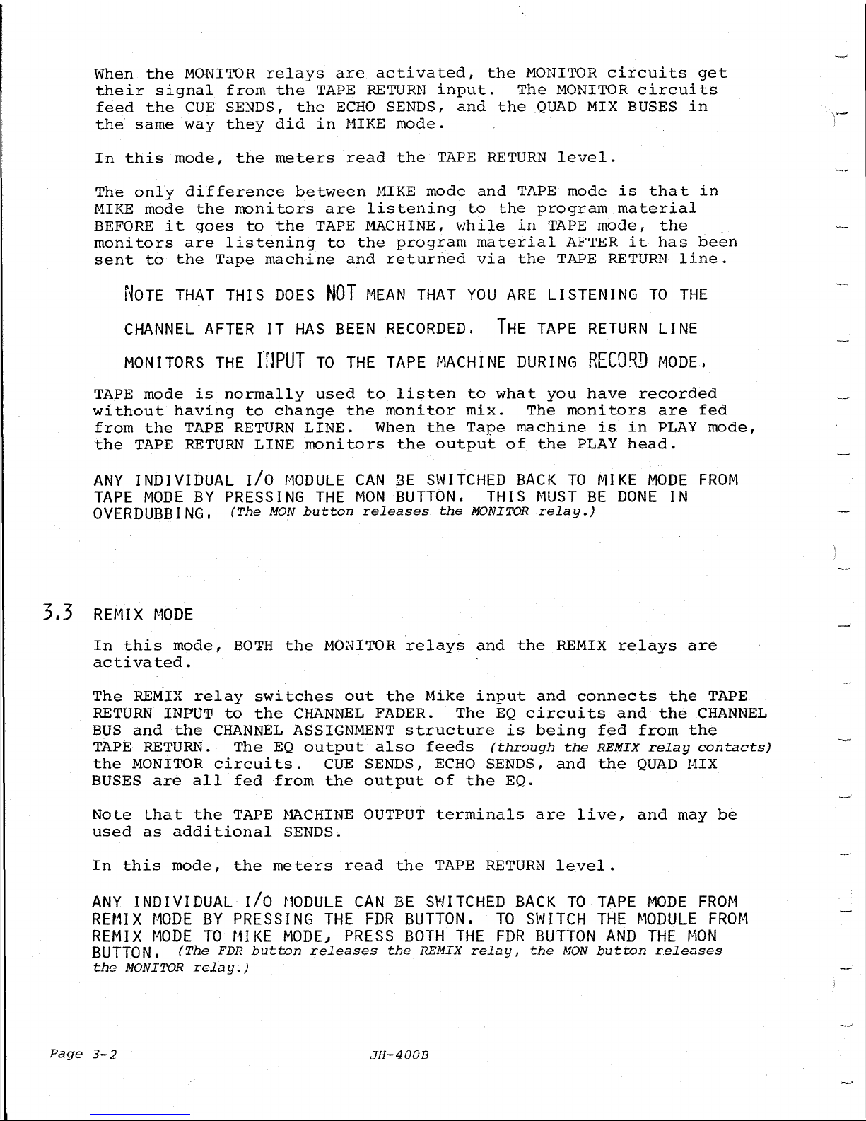
3.6
ECHO
SWIT,CH
In
REMIX
MODE,
the
ECHO
switch
is
a PRE
(fader)
- POST (EQ)
selector
for
the
input
to
ECHO
SEND
#1.
In
MIKE
or
'l'APE
mode,
the
ECHO
switch
is
used
as
a "WET"
switch
to
allow
ECHO
~o
be
recorded
on
the
MASTER
TAPE~
When
recording
ECHO, ~ feedback
loop
may
be
formed
unless
the
FEED POINT
to
the
ECHO
SEND
is
chosen
carefully.
The
following
BLOCK
DIAGRAMS
show
the
problem
and
the
solution:
Assign
Sw.
Channels
Buses
Pream12
1--~-tl-
-o--
&
EQ -
~c:>----'\JV\r
--=-~
'!'ape
>--e----~Recorder
Figure
11
Page
3-4
This
arrangement
produces
a
feedback
loop.
JH-400B
ECHO
Chamber
--
-
-
[
L
I
I..-
L
[
,_
3.7
-
!
I
'--
Preamp
&
~~----{
EQ
Figure
12
Assign
Sw.
LIGHT
METER
OPTION
Channel
Buses
Tape
>--.~--------~Recorder
ECHO
1--~---t
Chamber
No
feedback
loop
is
produced
by
this
arrangement.
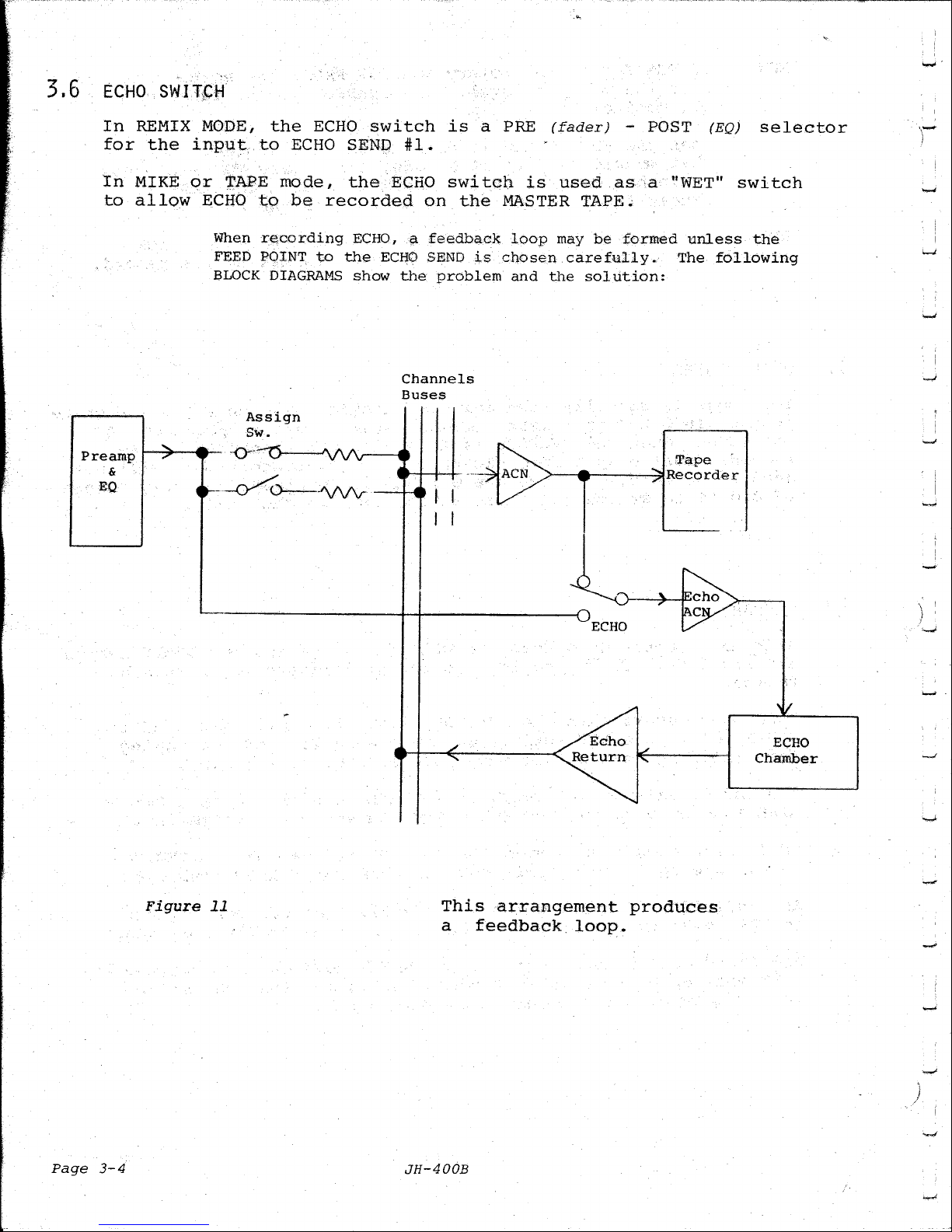
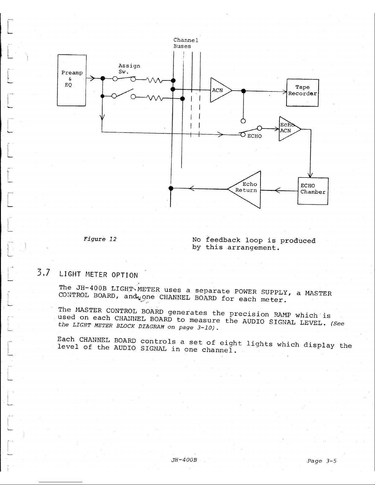
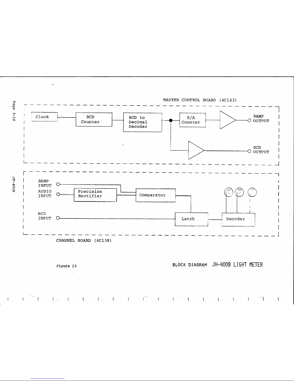
The
JH-400B
LIGH,T~·1<1ETER
uses
a
separate
POWER
SUPPLY,
a
MASTER
COJ:·JTROL
BOARD,
and.v
qne
CHANNEL
BOARD
for
each
meter.
....
~·
,,~
The
MASTER
CONTROL BOARD
generates
the
precision
RA~1P
which.
is
used
on
each
CHANNEL
BOARD
to
measure
the
AUDIO
SIGNAL
LEVEL.
(See
the
LIGHT
METER
BLOCK DIAGRAM
on
page
3-10)
.
Each
CHANNEL BOARD
controls
a
set
of
eight
lights
which
display
the
level
of
the
AUDIO
SIGNAL
in
one
channel.
JH-400B
Page
3-5

3.7.1
RAMP
GENERATOR
(See
Schematic,
Figure
29,
Page
10-21)
Two
"one
shot"
multivibrators
alternately
trigger
each
other
and
clock
a
BCD
COU~JTER
through
each
step
from
0000
to
1001
(0
through
9),
resets,
then
repeats
the
sequence.
The
counter
drives
a
BCD
TO
DECIMAL
DECODER
whose
decimal
outputs
go
LOW
as
the
equivalent
binary
input
is
fed
to
it.
The
DECODER
drives
a D/A
(Digital
to
Analog)
CONVERTER
which
is
contoured
to
produce
a
logarithmic
change
in
ten
steps.
The
VOLTAGE
DIVIDER,
R3-Rl2,
feeds
a
signal
voltage
to
IC5
which
varies
from
+15
volts
to
+7.5
volts,
depending
on
which
output
of
the
DECODER
is
?Ulled
to
ground
potential.
The
RA~1P
output
is
a
positive-going,
15
volt,
10
step,
logarithmic
shaped
wave,
with
a
repetition
rate
of
about
5
to
6
kHz.
The
BCD
information
developed
by
the
COUNTER
·is
also
fed
into
buses
to
be
used
by
all
of
the
Channel
Cards.
3.7.2
CHANNEL
BOARDS
(See
Schematic,
Figure28,
Page
10-19)
The
incoming
AUDIO
SIGHAL
is
rectified
and
filtered
to
produce
a
changing
DC
voltage
which
is
equivalent
to
the
AUDIO
LEVEL.
This
level
is
compared
to
the
RAMP
coming
from
the
MASTER
CONTROL
BOARD.
When
the
RAMP
exceeds
the
AUDIO SIGNAL
level,
the
cm1PARATOR
output
switches
to
the
positive
rail
and
sends
a
signal
to
the
QUAD
LATCH.
The
QUAD
LATCH
receives
as
its
input
signal,
BCD
information
from
the
MASTER
CO~TROL
BOARD.
This
BCD
information
is
IN
STEP
with
the
RAMP
(since
the
BCD
drives
the
D/A
converter
which
produces
the
RAMP).
When
the
COHPARATOR
switches,
the
QUAD
LATCH
is
clocked,
and
its
cutout
matches
the
input
it
is
receiving
at
the
moment.
NOTE:
The
QUAD
LATCH
CLOCK
works
ONLY
on
the
POSITIVE-GOING
EDGE
of
the
signal
•
It
will
not
resp:::>nd
to
either
a
HI
level
or a LO
level
signal.
The
DIGITAL
"WORD"
on
the
out?Ut
of
the
QUAD
LATCH
is
held
until
a
new
CLOCK
PULSE
is
received
from
the
COMPARATOR.
The
output
of
the
QUAD
LATCH
drives
a
BCD
TO
DECIMAL
DECODER.
The
decimal
output
corresponding
to
the
digital
"WORD"
goes
to
ground
potential
and
turns
ON
its
light.
NOTE:
Outputs
corresponding
to
"0"
and
"1"
have
not
been
supplied
with
a
light·
This
means
that
the
DISPLAY
is
unlighted
when
the
AUDIO
SIGNAL
is
at
its
lowest
level.
A
NEW
LEVEL
COMPARISON
IS
COMPLETED
EVERY
0.2
MILLISECONDS,
JH-400B
Page
3-9
--
- - -
--
----
-·-
-
Clock
i
BCD
BCD
to
Counter
Decimal
Decoder
MASTER
CONTROL
BOARD
(4Cl43)
-----------l
D/A
Counter
l
RAMP
OUTPUT
:...._____j[>·
>-------4
BCD
0
OUTPUT
I
I
I
I
I
I
I
L
____
_
-------------
- - - - - -
·-
··- - - - - _J
r-
'
I
I
I
I
I
I
I
RAMP
INPUT
AUDIO
J;NPUT
BCD
INPUT
----------------
Precision
I
Rectifier
Comparator
--------------,
l
!
Latch
I
~----------j
,..-1---l..------L,
Decoder
I
i
'
I
I
I
I
I
I
I
L
________
_
----------------------
_j
CHANNEL
BOARD
(4Cl38)
Figure
13
BLOCK
DIAGRAM
JH-400B
LIGHT
METER
L
L

TROUBLESHOOTING
 Loading...