

MCi J4500 Operator's Manual


TABLE OF CONTENTS
1-- Introduction 1..............................................
2--Daily Inspections 5.........................................
3--Switches, Warning Lights and Gauges 9.....................
4-- Steering Column and Floor -Mounted Controls 25..............
5-- Operating Features 29.......................................
6--Wheelchair Lift 31...........................................
7-- Engine Operation, Fuel and Exhaust 39.......................
8--Transmission Operation 43...................................
9-- Emergency Conditions 47....................................
10--Heating and Air Conditioning (HVAC) 55.....................
11--Audio and Video Systems 57................................
12--Service and Maintenance 63.................................
13--Specifications 73...........................................
14--Diagnostic Codes 77........................................
15--Index 85...................................................
16--Figure Index 90.............................................
1 - INTRODUCTION
Typical illustrations may be used, therefore
minor illustration differences may exist when
compared to actual parts or other
publications
COACH APPLICABILITY
This manual supports the MCI J4500 Coach.
TO THE DRIVER
This manual has been prepared to provide you with the
information you need to operate the MCI J4500 Series
Coach.
The specifications and information throughout this
manual are subject to change without notice.
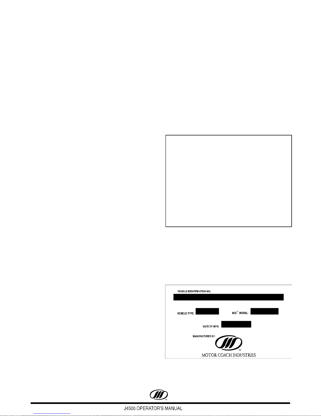
CERTIFICATION PLATE
The certification plate ( Figure 1 ) is affixed beside the
driver's seat base, and certifies compliance with all
applicable Federal Motor Vehicle Safety Standards in
effect on the date of manufacture. It also lists the date
the coach was built, the GVWR, GAWR's, rim size, tire
pressures, coach model and coach serial number.
EMISSION CONTROL INFORMATION
DECAL
The emission control decal is affixed directly below the
certification plate shown in Figure 1.
Report immediately any problem or
malfunction that interferes with the operation
of the coach, particularly if safety may be
affected.
The term “Optional” in this manual pertains to all
equipment and features other than basic.
MCI SERVICE NUMBER: 1-800-241-2947
This manual is a permanent part of this vehicle.
It must stay with the coach if the coach is sold.
PUBLICATION DATE: June 2016
EFFECTIVE WITH UNIT NUMBER 67758
MCI PUBLICATION PART #.: 03-26-1426
Figure 1.
COACH NAMEPLATE
The nameplate ( Figure 2 ) is mounted in the engine
compartment at the rear of the coach. The vehicle
identification number (VIN), model year and date of
manufacture are shown on this plate.
Figure 2.
1June 2016

VEHICLE IDENTIFICATION NUMBER (VIN)
The nameplate and the certification plate both contain
the seventeen-character vehicle identification number
(VIN).The numbers correspond to the items in the
following list.
1. The first three characters identify the
manufacturing company:
1M8 = MCI Inc. (U.S.)
2MG = MCI Ltd. (Canada)
2. The fourth character identifies the coach model:
3 = J4500 Intercity
3. The fifth character identifies the series:
J = J-Series
4. The sixth character identifies the type of coach:
M = Intercity (MCI)
P = Incomplete Vehicle
5. The seventh character identifies the type of
engine:
B = Cummins ISX
8 = Detroit Diesel DD1
6. The eighth character identifies the type of
brakes:
A = Air Brake Intercity
7. The ninth character is the check number.
8. The tenth character identifies the year:
H = 2017
9. The eleventh character identifies the
manufacturing location:
W = Winnipeg, Manitoba
10. The twelfth through seventeenth characters is
the coach's unit number.
6
June 20162

Figure 3. Driver’s Area
1
2
3
4
5
6
7
8
9
1. Instrument Panel
• System Gauges
• LH Tell-tale Cluster
• RH Tell-tale Cluster
• Driver’s Vents
2. Lower, LH Console
• Cup Holder
• Headlight Switch
• Mirror Controls
• Pushbutton Shift Selector
• Switches
• Wheelchair Master Switch ( Optional )
• 12 Volt Power Source
• Anti-Slip Pad
• Emergency Park Brake Release
• Front Service Compartment Door
Release
3. LH Switch Panel
• Driver’s Fan Control
• Driver’s Heat Control
• Micromate Control Panel
• Switches
4. RH Switch Panel
5. Steering Column
6. Entrance Door Override Valve
7. Amerex Fire Suppresion System Manual Fire
8. Microphone Receptacle
9. Certification and Emission Control Plate
• Switches
• Audio and Video System Controls
• Steering Wheel with Switch Pods
• Electric Horn
• Smart Stick Control, featuring Turn
Signals, Air Horn, Headlamp Dimmer,
Windshield Wipers and Washer
• Tilt and Telescoping Control Lever
Button
3June 2016

THIS PAGE INTENTIONALLY LEFT BLANK
June 20164

2 - DAILY INSPECTIONS
The following checks are in addition to the Federal Motor Carrier Safety Administration requirements,
not instead of them.
EXTERIOR INSPECTION
1. Ensure that all windows, mirrors and lights are
clean and unobstructed.
2. Ensure that all side windows are closed.
A protrusion of 1/4” ( 6mm ) or more indicates
that a window in not properly latched.
3. Check that the coach exterior is clear of debris,
and that all service doors are secure.
4. Check the tire pressure and inspect the tires for
damage. Check that the wheel nuts are tight
and inspect the wheels for damage.
INTERIOR COMPONENTS CHECKLIST
1. Ensure that the door(s), hatches and
emergency exit windows open, close, seal and
latch properly.
2. Check the brake pedal and linkage for any
obstruction that may prevent the brake from
being applied or completely releasing.
3. Ensure that the parcel rack doors are latched.
4. Inspect the seats and floor for debris. Clean if
necessary.
5. Look under the coach for fluid leaks, animals or
obstructions. Check behind the coach.
6. Check the engine oil level, coolant level,
condition of belts and power steering fluid level.
7. Check the engine compartment to ensure that
there are no loose or unsecured objects.
8. Check the windshield washer reservoir and fill if
required.
9. Ensure that the engine compartment remote
control box ENGINE ENABLE switch is ON and
the STARTER CONTROL switch is set to
FRONT.
10. Turn ON the main electrical switch.
11. Press the Step-well light switch to the ON
position.
5. Ensure that the interior and step-well lights
work.
6. Ensure that the lavatory door, windows and
wheelchair access door ( if equipped ) are
closed and latched.
7. Ensure that emergency equipment and
contents are in place and properly stowed.
8. Activate the entertainment control module and
verify the operation of the driver's and cordless
microphones ( if equipped ). Adjust output
volume if necessary.
Before starting ensure that the fast idle is OFF
and the parking brake is applied. Ensure that
there is ample distance ahead of and behind
the coach in case it moves unexpectedly
during starting.
DO NOT rev the engine while starting.
5June 2016

The following checks are in addition to the Federal Motor Carrier Safety Administration requirements,
not instead of them.
OPERATIONAL CHECKLIST
1. While the engine is running, look for oil or
coolant leaks and listen for air leaks.
2. While the engine is running, check the
alternator lights on the remote control box in the
engine compartment. The lights should be OFF.
Be very careful when the engine is running
and the engine door is open.
If it is necessary to have the engine running
for certain inspections or checks, keep a safe
distance from moving belts, pulleys, shafts or
fans.
Keep hands and limbs away from moving
belts and pulleys and also hot areas such as
exhaust and turbocharger components and
coolant lines.
Do not wear loose, baggy or frayed clothing
when working near any moving parts such as
pulleys, belts, shafts or fans.
3. Close and secure all baggage and service
doors.
4. Ensure that all exterior lights are working.
5. If the coach is equipped with a wheelchair lift,
check the lift operation. For more information
refer to the vendor manual.
7. Position the inside and outside mirrors, adjust
the driver's seat and fasten the seat belt.
8. Ensure that the tilt steering column is locked.
9. Ensure that the defroster, heater, horn,
windshield wipers and washers all function.
Do not move the coach until the front and rear
air gauges both read at least 100 psi.
10. Apply the service brakes, release the park
brake, then release the service brakes.
11. Apply and hold the brakes and observe the
pressure drop. It should not drop by more than
3 psi in 1 minute.
12. Move the coach slowly and bring it to a stop to
ensure that the brakes stop and hold the coach.
13. Ensure that brake pedal operation feels normal.
14. Ensure that all gauges stay in normal range.
15. Move the coach a short distance at low speed
and check the steering. Ensure that the coach
is under full control and handling properly. The
steering wheel must turn smoothly without any
unusual noises.
6. After the HVAC system has stabilized ( 10 to 15
minutes ), listen for abnormal noises in the
compressor and fan motors; check the
compressor oil level and check the refrigerant
level. Ensure that the self-test has been
performed successfully and that there are no
errors or alarms indicated.
June 20166

DRIVER'S SEAT BELT
MIRRORS
Driver's Seat Belt Adjustment
Using the restraint system can lessen the
severity of injury in an accident or sudden
maneuver.
While seated straight and well back into the seat,
adjust the belt as necessary.
To unfasten the belt, push the release button.
If a belt jams, you may be able to release it by
working the belt in and out until the belt rewinds far
enough to unlock. If the belt remains jammed or
other restraint system parts do not work properly,
report the condition to service personnel promptly.
Seat Belt Inspection
Every 30 days, check the belt, buckle, latch plate,
retractor and guide loops for proper operation.
Check for loose or damaged parts. Keep sharp
edges and sharp objects away from belts and other
parts of the restraint system.
Inside Rear-view Mirrors ( Optional )
The inside rear-view mirrors can be manually
adjusted up, down or sideways.
Exterior Rear-view Mirrors
Exterior mirrors have separate upper and lower
segments. The convex upper portion is for wideangle view.
Adjust the exterior mirrors so that you can see the
side of the coach in part of the mirror. This helps
determine the relationship of the coach to objects
seen in the mirror.
The roadside and curbside mirror controls are on
the lower LH console switch panel. Use the switch
in the center of each mirror control to select the
upper or lower mirror. Move the switch to the left to
adjust the lower mirror and to the right to adjust the
upper mirror.
Defrost the mirrors using the mirror heat switch
located below the mirror controls.
Keep the belts clean and dry. Replace belts if the
webbing appears frayed, cut or damaged. Replace
belts that have been involved in an accident. Have
parts replaced if there are any questions as to their
condition. Clean seat belts with mild soap and
lukewarm water only; do not bleach or dye.
7June 2016

PRE-TRIP INSPECTION,
INTERIOR / EXTERIOR LIGHTING
ANTI-THEFT PRECAUTIONS
Before the Pre-Trip Inspection function is
enabled, these functions must be met:
• Position the Master Power switch to the
“ON” position,
• Select “NEUTRAL” on the transmission
Shift Pad selector,
• Set the Park Brake,
• Position the Reading Light test switch to
the “ON” position.
• Apply and hold a service brake
application of 60 psi,
Only after these conditions are met, the Pre-Trip
Inspection function is enabled, automatically activating
all interior / exterior coach lighting and dash tell-tale
lights and buzzer will activate for two (2) minutes.
1. Do not leave the coach unattended with the
engine running.
2. Park in a lighted spot when possible.
3. Fully close all windows and doors.
4. Keep valuable items out of sight.
5. Press the Step-well light switch to the OFF
position ( anti-theft feature ).
6. Lock out the battery disconnect switch
The back-up lights do not illuminate during
the Pre-Trip Inspection.
The Pre-Trip Inspection function can be
canceled by positioning the Reading Light
test switch to “OFF”, or positioning the
Hazard switch to “ON”.
June 20168

3 - SWITCHES, WARNING LIGHTS AND GAUGES
2
4
6
Instrument Panel Components
1. Gauges
2. LH Tell-tale Cluster
3. RH Tell-tale Cluster
4. LH Switch Panel
5. RH Switch Panel
6. Vent
3
5
1
6
Figure 4. Instrument Panel
9June 2016

Figure 5. Instrument Panel Gauges
INSTRUMENT PANEL/GAUGES
Speedometer
The speedometer, which features an alphanumeric
message display, reads the forward speed of the coach
in miles per hour or kilometers per hour. The
speedometer features a MODE and TRIP button allow
the driver to select, set/reset displays and scroll
through active system warning messages, when the
coach is at a complete stop.
The MODE button is utilized to select the mode of
operation for the message display and to clear priority
messages.
The TRIP button is utilized to change what is
displayed on the lower line of the alphanumeric
message display.
The following settings can be selected on the
screen by utilizing the MODE and/or TRIP buttons
shown in Figure 7:
- Imperial / Metric Units,
- Contrast Adjust,
- Display Language (English, Spanish or French)
- Diagnostics Menu.
Figure 6. Speedometer
Figure 7. Alphanumeric Display
June 201610

4-in-1 Gauge
4
Front ( PSI ) Air Pressure - The secondary air
pressure gauge reads front brake air reservoir
pressure in pounds per square inch or kilo-pascals. If
the pressure is low during start-up, the LED lights
3
2
and a buzzer sounds. The alarms stop when the
pressure builds up to operating level. Do not operate
the coach under 100 psi (690 kPa).
Rear ( PSI ) Air Pressure - The primary air
pressure gauge reads rear brake air reservoir pressure
in pounds per square inch or kilo-pascals. If the
pressure is low during start-up, the LED lights and a
buzzer sounds. The alarms stop wh en the pressure
builds up to operating level. Do not operate the coach
under 100 psi ( 690 kPa ).
1
Figure 8. 4 in 1 Gauge tell-tales
1. Front Air PSI tell-tale
The low air warning tell-tale illuminates when the air
pressure drops below the pre-determined level.
In the event of a low air warning, stop the coach and
determine the cause of air loss before proceeding.
2. Rear Air PSI tell-tale
The low air warning tell-tale illuminates when the air
pressure drops below the pre-determined level.
In the event of a low air warning, stop the coach and
determine the cause of air loss before proceeding.
3. Water Temperature tell-tale
Tell-tale illuminates when the coolant temperature is
above normal. Obtain service as soon as possible.
4. Oil Pressure tell-tale
Tell-tale illuminates when the oil pressure is too low.
If a low air warning activates during driving,
stop the coach immediately and find the
cause of the air loss. If brake reservoir
pressure drops significantly, the parking
brakes apply automatically.
Oil Pressure - The oil pressure gauge reads
engine oil pressure in pounds per square inch or kilo
Pascals. Oil pressure should be between 50 - 70 psi
( 345 - 483 kPa ). The LED lights when the oil
pressure is too low.
Coolant ( Water ) Temperature - The coolant
temperature gauge reads engine coolant temperature
in degrees Fahrenheit or Celsius. The normal
operating range is 160-226F ( 71-108C ). The LED
lights when the temperature is above normal. Obtain
service as soon as possible.
Low air pressure will illuminate the LOW AIR
lamp and a buzzer will sound, indicating that
the air pressure is too low. Stop coach and
determine reason for pressure loss.
DO NOT operate the coach under 100 psi air
pressure.
11June 2016

3-in-1 Gauge:
Figure 9. 3 in 1 Gauge
Fuel - This gauge reads the fuel level in the tank.
Diesel Exhaust Fluid ( DEF ) - The DEF gauge
reads the fluid level in the tank.
Figure 11. SmarTire SmartWave FFD
SmarTire SmartWave Full Function Display -
The SmartWave tire monitor system provides tire
pressure deviation alert, low pressure warning and
high temperature alert for all tire positions.
Engine Tachometer - The engine tachometer
reads engine revolutions per minute.
Figure 10. Volt and Trans Temp Gauges
Voltmeter - The voltmeter reads the condition of
the 24-volt electrical system. The gauge is calibrated
in volts. The needle should be from 27 to 29 volts. If
below 27 volts, the batteries are undercharging. If
above 29 volts, the batteries are overcharging. Have
the system checked if over- or undercharging. The
LED lights when voltage is too low.
SmartWave display functions:
1. ALARM tell-tale light to alert driver.
2. Display screen shows alert icons, tire location
and numerical unit of pressure or temperature.
3. Control buttons to scroll through display.
Transmission Temperature - This gauge reads
transmission oil temperature in farenheit.
June 201612

TELL-TALE LAMPS
Left Turn Indicator (Green)
Wait to Start (Yellow) - This tell-tale will
illuminate when the grid heater is ON
(pre-heat function).
Check Engine (Yellow) - Engine fault.
Refer to vendor manual.
Stop Engine (Red) - Engine is powering
down or stopped.
Low Coolant (Yellow) - Tell-tale indicates
a low engine coolant level. Do not run
engine until condition is corrected.
Not Generating (Red) - Tell-tale
indicates that one or both alternators are
not functioning.
Regeneration (DPF) (Yellow) - Tell-tale
illuminates when a regeneration is
required. Tell-tale is OFF during Regen.
High Exhaust Temperatures (HET)
(Yellow) - Tell-tale will illuminate when the
coach is moving less than 5 mph (approx.)
and the exhaust outlet temperature
exceeds the predetermined level.
Diesel Exhaust Fluid (DEF) (Yellow) - Telltale illuminates indicating the DEF level is
low. Correct by refilling the DEF tank.
DEF tell-tale flashes indicating the DEF level
has fallen below a critical level. Correct by
refilling the DEF tank.
DEF tell-tale flashes and Check Engine
illuminates indicating the DEF level is critically
low and power loss will occur. Normal engine
power will be restored by refilling the DEF
tank.
DEF tell-tale flashes and Check Engine and
Stop Engine illuminates indicating the DEF
tank has been run dry. Engine will De-rate and
limit speed to 5 MPH. Normal engine power
and coach speed will restored by refilling the
DEF tank.
Tell-tales indicate various conditions by lighting. In general, yellow indicates system status and red indicates a fault
or warning. Tell-tales are located in RH and LH clusters, in the instrument cluster. Some tell-tales are accompanied
by a buzzer or bell. At system start-up, tell-tales light briefly to show that the LEDs work.
LH TELL-TALE CLUSTER
Figure 12. LH Tell-tale Cluster
13June 2016

MIL (Yellow) - Malfunction Indicator Tell
tale Lamp. Tell-tale indicates a failure of an
emission system component.
Blank
Water in Fuel (Yellow) - Tell-tale indicates
water in the fuel filter.
Park Brake Applied (Red)
Trailer Park (Red) - Tell-tale is disabled.
ABS (Yellow) - Tell-tale indicates anti-lock
braking system malfunction.
Electronic Stability Control / Automatic
Traction Control (Yellow) - Tell-tale
indicates an Electronic Stability Control
(ESC) or an Automatic Traction Control
(ATC) event.
Brake Lights (Green) - Tell-tale illuminates
throughout the service brake application.
Engine Brake (Yellow) - Tell-tale indicates
the engine brake is activated.
Check Transmission (Yellow) - Move the
coach to a safe location and turn OFF
ignition. DO NOT change gear.
Stop Transmission (Red) - Tell-tale is
disabled.
Retarder Temperature (Red) - Tell-tale
illuminates when retarder oil temperature is
above 168 degrees Celsius for more than
ten (10) seconds.
Brake Wear (Yellow) - Tell-tale is disabled.
Fuel Filter Restriction (Yellow) -
Indicates the fuel filter has been clogged.
Tag Lock Fault (Red) - Tell-tale illuminates
when coach speed reaches 15 mph and
the tag cylinder does not lock.
Tell tale is OFF when coach speed returns
to 10 mph.
No Hill Start (Yellow) - Tell-tale is
disabled.
June 201614

RH TELL-TALE CLUSTER
Driver Seat Belt (Red) - Tell-tale lights
when park brake is released and the
driver's seat belt is not buckled.
Check Info (Yellow) - Tell-tale indicates
message on alphanumeric display of
speedometer. Refer to next page for further
information.
Low Fuel (Yellow) - Tell-tale will illuminate
when fuel level is below 12 percent
(approx.) left in the tank.
Cruise Enabled (Green) - Tell-tale
indicates that the cruise control is
activated.
High Beams (Blue) - Hi-beam tell-tale will
illuminate when the main headlamps are on
HIGH intensity.
Right Turn Indicator (Green)
Rear Rise (Red) - Tell-tale illuminates and
a buzzer sounds when the Rear Rise
switched is pressed.
High Ride (Red) - Tell-tale will illuminate
and a buzzer sounds when the coach is in
transition and is maintained in HIGH RIDE.
Low Ride (Red) - Tell-tale flashes when
the coach is in transition to and is
maintained in LOW RIDE.
Ride Fault (Red) - Tell-tale illuminates
when a fault has occurred in the MDSS.
Report problem to maintenance personnel.
Kneel (Red) - Tell-tale flashes and a
buzzer sounds when the coach is kneeling
or recovering. When kneel is reached, the
lamp stays on and the buzzer stops.
Tag Unload (Red) - Tell-tale Illuminates
when the tag axle is unloaded.
WCL Door Open (Red) - Tell-tale will
illuminate indicating door ajar or
unlocked condition.
Figure 13. RH Tell-tale Cluster
15June 2016

WCL Interlock (Red) - Tell-tale illuminates
when the wheelchair lift interlock is
activated. The wheelchair interlock system,
when activated, disables the transmission
shift and throttle, sets the park brake
solenoid, and begins engine fast idle.
Front Door Open (Red) - Tell-tale light
illuminates when the entrance door is open.
WCL Stop Request (Blue) - Illuminates
Check Lube (Yellow) - Tell-tale is
disabled.
Back-up Alarm Off (Yellow)- Tell-tale is
disabled.
when a passenger in the wheelchair area
presses the stop button.
Lavatory Emergency (Yellow)- Tell-tale
illuminates when a passenger presses the
emergency button in the lavatory.
CHECK INFO TELL-TALE
Stop Request (Yellow) - Tell-tale lights
when a passenger presses the stop
request button.
Aux. Heat (Yellow) - Illuminates when the
auxiliary heater has been activated.
Fire Alarm (Red) - Illuminates when the
temperature sensors sense heat from a fire
in the engine compartment.
Emergency Lights (Yellow) - Tell-tale is
disabled.
Dock Lights (Blue) - Tell-tale is disabled.
Service Lights (Yellow) - Tell-tale
indicates engine compartment. light is ON.
The CHECK INFO tell-tale illumination indicates
that a message regarding additional tell-tale
information is displayed on the alphanumeric display of
speedometer. Dependant of the message displayed, a
buzzer may accompany the message.
Move the coach to a safe parking area to view the
message displayed on the alphanumeric display of
speedometer. After the message has been recorded,
the operator can press the TRIP button to dismiss the
message. The CHECK INFO tell-tale will remain
illuminated, but the message will not appear in the
alphanumeric display of speedometer until the system
re-broadcasts the signal.
The tell-tale information displayed on the
alphanumeric display of speedometer are
BACKUP ALARM, Digital Wheel End Sensor (WHL END),
TAG LOCK, SHOW MODE
and ALTERNATOR NOT GEN.
FAST IDLE,
The following Starter Diagnostic messages will
display when the
ENGINE START switch is pressed but
a condition is preventing the engine from cranking:
FRONT MODE SW, REAR RUN SW, TURN ON IGN,
SELECT NEUTRAL and STARTER LOCKOUT.
Bike Rack (Yellow) - Tell-tale is disabled.
Figure 14. Alphanumeric Display
June 201616

5. Override - Press to override an emergency
8
1
2
3
4
5
6
7
engine shutdown for 30 seconds. Press as
often as necessary to move coach to safe
parking.
This switch allows the operator to override an
emergency shutdown due to an engine
malfunction. Pressing the switch allows the
operator to run the engine for an additional 30
seconds so that the operator can move the
coach to a safe parking area.
In a driving situation, the override switch
should be utilized only to safely move the
coach to a safe parking area.
The engine overrule feature is not intended to
provide a ”limp home” capability. T his feature
should not be utilized to extend coach driving
to a garage or other destination, as engine
damage may result from over-extension of the
safety feature limitations.
Figure 15. - LH Switch Panel
LH SWITCH PANEL
1. Fog Lights Switch
2. Mirror Heat Switch - Press this switch to clear
the mirrors of fog and frost.
3. Parcel Rack Blower Switch - The PARCEL
RACK switch controls the parcel rack blowers,
LOW, OFF and HIGH.
4. Auxiliary Heater Switch - When the engine is
OFF, the engine can be preheated by pushing
the AUXILIARY HEATER switch forward, which
activates a 90 minute timer in the Proheat unit.
When the Proheat burner is ON, the HEATER
ON telltale lights.
To turn the Proheat OFF, push the switch back. It
will purge for 2 to 3 minutes. If the coach is
started during preheating, the temperatureDependant control overrides the timer.
6. Blank
7. Master Power Switch - Pressing this switch to
the ON (upper) position will enable all of the
multiplex modules and turn on the coach's
electrical system.
8. Engine Start Switch - Used to start the coach
using the rocker switch ignition.
To START the coach using the rocker switch
ignition, place the master power switch in the ON
(upper) position as well as the Step-well Light
switch. Press the upper portion of the engine
start momentary-on spring return switch to
engage the starter. Release the switch once the
coach has started.
Allow the coach to idle for 30 seconds.
To STOP the engine, place the master power
switch in the OFF (lower) position.
17June 2016

Figure 16. RH Switch Panel
1
2
3
4
5
6
7
8
9
11
10
13
14
15
12
RH SWITCH PANEL
1. Interior Light
2. Reading Lights - Turns reading lights ON and
OFF.
3. Blank Switch
4. Baggage Bay Lights - Turns the baggage bay
lights ON and OFF. The baggage bay lights
have a timer feature that automatically shuts
OFF the lights after 30 minutes, if the switch is
left in the ON position.
5. LH Baggage Lock - Locks and unlocks the LH
hand baggage doors.
6. RH Baggage Lock - Locks and unlocks the RH
hand baggage doors.
7. Kneeling - With the park brake applied, the
transmission in Neutral and the entrance door
closed, press and hold the KNEEL half of the
switch to lower the front of the coach 5" (127
mm).
8. Entrance Door Open/Close - Press and hold
the upper half of the switch to open the door.
Press and hold the switch to close the door.
Door movement stops if the switch is released.
9. Panel Lights - This switch controls the desired
panel brightness
10. Driver's Light - Turns lights on in the driver's
compartment.
11. Step-well Lights - When this switch is ON, the
step-well lights turn ON whenever the entrance
door opens. The switch must be ON for the
anti-theft feature to allow the coach to start.
12. Blue LED Light ( Optional )
13. Event Switch - Pressing this switch will
interrupt any audio or video, and play a prerecorded message.
14. Blank Switch
15. Hazard/Warning Lights - Flashes all front, rear
and side-mounted turn signal lights and both
telltales simultaneously.
June 201618

Figure 17. Lower, LH Console Switch Panel
1
2
3
4
5
6
7
8
9
10
11
12
13
14
15
16
17
18
19
LOWER LH CONSOLE SWITCH PANEL
1. Cup Holder
2. Headlight Switch
3. Mirror Controls - Adjust the RH and LH exterior
mirror heads (upper and lower).
4. 110 Volt - Press to turn ON the inverter and
supply power to passenger outlets.
5. Tag Lock / Auto Switch - Press the upper half,
LOCK, of the momentary switch to lock the tag
cylinder. The CHECK INFO tell tale flashes and
the alphanumeric display on th e speedometer
will display TAG LOCK.
When coach speed reaches 15 mph, the
alphanumeric display on the speedometer will stop
displaying the TAG LOCK message.
When coach speed reaches 10 mph and lower, the
tag cylinder will remain locked and the alphanumeric
display on the speedometer will display the TAG LOCK
message.
The tag cylinder can only be unlocked by pressing
the lower half, AUTO, of th e momentary switch or by
cycling the ignition.
6. Mud/Snow - On extra soft surfaces (snow, mud
or gravel), press the MUD/SNOW switch to
increase traction by slightly increasing permissible
wheel spin. The LOW TRACTION or ES C / A TC
telltale will blink continuously when MUD/SNOW is
active. Press the s witch again t o turn of f MUD/
SNOW. (Turning off the ignition also resets the
MUD/SNOW feature.)
7. Fast Idle - Place the transmission in Neutral,
apply the parking brakes and turn FAST IDLE on to
increase engine idle speed for engine warm-up, air
pressure build-up or A/C operation when the coach
is parked. Return the switch to n ormal when fast
idle is not required.
19June 2016

8. Tag Axle Unload - Press to unload the tag axle
to improve traction on the drive axle. Press again to
transfer the load back to the tag axle.
Only unload the tag axle in low traction
situations.
9. Rear Rise - When the coach is traveling under
20 mph (30 kph) and the RAISE half of the switch is
pressed, the rear of the coach rises, the HIGH
RIDE telltale lights and a buzzer sounds.
Pressing the lower section of the switch or traveling
above 20 mph (30 kph) returns the coach to normal
ride height.
10. Level Control Switch - Press the UPPER half
of the switch to raise the front and rear suspension
to the High Ride parameter height. Press the
LOWER half to lower the front and rear suspension
to Low Ride parameter height.
11. Normal Ride / Recover - Press switch to reset
front and rear suspension to Normal Ride height.
12. LH Blind Switch
13. RH Blind Switch
14. 12-Volt Power Source
15. Pushbutton Shift Selector ( PBSS )
16. Wheelchair Master Switch ( Optional )
17. Emergency Park Brake Release
18. Front Service Compartment Door Release
19. Emergency Seat Belt Cutter Tool
June 201620

Regeneration Switch
The regeneration toggle switch is located in the
rear, side service compartment.
To avoid serious personal injury or property
damage, ensure that no persons or objects
are at or within two feet of the exhaust outlet
at any time during a regeneration. Ensure that
exhaust and outlet are clear of any trash,
grasses, or other vegetation or debris.
Use extreme caution during a stationary
regeneration, as exhaust gas tail pipe outlet
temperatures can exceed 900 degrees F ( 482
degrees C ). Stationary regenerations are to
be performed outdoors only.
DO NOT leave the coach unattended during a
stationary regeneration.
DO NOT perform inside a garage or
maintenance facility.
DO NOT attach an exhaust extraction hose to
the exhaust outlet.
PARKING BRAKES
The coach has air-release spring activated parking
brakes. The Parking Brake control is a black, button
located under the LH switch panel.
Do not leave the coach without applying the
parking brake.
Figure 19. Parking Brake Knob
Normal Park Brake Operation
1. Stop the coach, put the transmission in neutral.
2. Pull the park brake knob out ( Figure 19 ) to set
the park brake. The valve will latch in this
position.
3. Ensure that the air pressure gauge shows 100
psi (689 Pa) or more.
4. Push the park brake knob fully in to release the
brakes. The valve will latch in this position.
Emergency Park Brake Release
In an emergency, where there is no pressure or
low pressure in the air system, the parking brake can
be released by pushing and holding down the
Emergency Park Brake Release.
Figure 18. Regen Switch
Park Brake Interlocks
The parking brake is interlocked with and affects
the operation of kneeling and wcl as follows:
• Kneeling - The park brake must be applied
to kneel. Releasing the park brake cancels
kneeling and returns the coach to normal ride
height.
• Wheelchair Lift - The park brake is
interlocked by the wheelchair lift key switch. The park
brake must be set before turning the wheelchair lift
master key switch on. Opening the wheelchair lift doors
also sets the parking brake.
The park brake emergency release air tank
has only enough air to release the parking
brake three times.
The Emergency Park Brake Release is a green,
circular button located on the lower LH console switch
panel ( Figure 20 ).
Figure 20. Emergency Park Brake Release
21June 2016

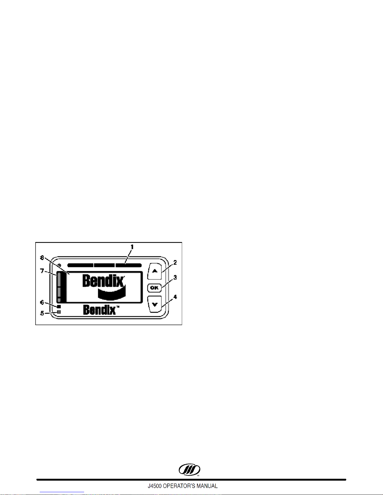
Bendix Wingman System (Optional)
Figure 21.
The Driver is always responsible for the
control and the safe operation of the vehicle
at all times. The Bendix Wingman Advanced
(or ACB) system does not replace the need
for a skilled, alert professional driver,
reacting appropriately and in a timely
manner, and using safe driving practices.
Any audible and/or visual alert by the system
means that your vehicle is too close to the
vehicle ahead, immediately act to potentially
avoid, or lessen the severity of, a collision.
Improper use of the Bendix Wingman
Advanced ( or ACB ) system can result in a
collision causing property damage, serious
injuries, or death.
Active Cruise with Braking (ACB)
The Wingman system is engaged by turning cruise
control ON and setting the vehicle speed. The system
helps maintain a set distance between the operated
vehicle and a detected vehicle ahead. To disengage
the system, turn the cruise control OFF or press the
brake pedal.
The Wingman Advanced ( or ACB ) system is
automatically ready when the cruise control
is set. However, cruise control must be used
only in the same conditions that are normally
recommended for ordinary cruise control. As
noted below, there are certain situations
when cruise control should NOT be used. Do
not use cruise control in the following
conditions or situations:
• Inclement weather (rain, snow, fog,
ice or other severe weather
conditions)
• Dense Traffic
• Sharp curves and winding roads
• Entrance or exit ramps
• Downhill grades
• Construction zones
• Smaller forward vehicles - Smaller
vehicles, such as motorcycles, may
be difficult for the radar to identify. It
is the driver’s responsibility to be
aware of these types of vehicles and
to slow down if necessary.
Any vehicle trouble code that disables
vehicle cruise control will also cause a
diagnostic trouble code in Wingman
Advanced ( or ACB ). The Wingman system
will not operate until the DTC is cleared.
Collision Mitigation (Advanced)
Audible and visual alerts are provided to the
operator through a Driver Interface Unit (DIU). All the
alerts are always active regardless whether cruise
control is engaged or not. Any alert means your vehicle
is too close to another vehicle or object. These alerts
will change as the distance between the two vehicles
decreases alerting the operator of the impending
hazard. As the distance closes, the system will
automatically intervene and slow the vehicle.
June 201622
The radar system only senses metallic
objects. Non-metallic or limited metallic
objects such as people, animals, RVs,
motorcycles, horse drawn buggies, logging
vehicles, or cross- traffic will not trigger the
system.
Due to inherent limitations of radar
technology, the collision mitigation
technology on rare occasions may not detect
moving vehicles or stationary objects in your
vehicle’s lane of travel.
Road curvature may impact the radar’s ability
to track vehicles ahead in the same lane.
Operator alerts, warnings, or brake
interventions may not occur. In addition, the
system may react to moving vehicles not in
your vehicle’s lane of travel. Operator alerts,
warnings, or brake interventions may occur.
Following Distance Alert (FDA)
A FDA is generated through the DIU using vehicle
speed, forward vehicle speed, distance and driving
scenarios.
These alerts indicate that the time between
your vehicle and the detected forward vehicle
ahead is less than one and a half ( 1.5 )
seconds and decreasing. Once the audible
alert is heard, the driver should increase the
distance between their vehicle and the vehicle
ahead until the audible alert stops.
Single, Yellow Illuminated LED
The forward vehicle is within a 1.5 seconds range
and traveling at the same speed or slower.
The screen will visually show the distance between
the vehicles, closing.
Two, Yellow Illuminated LEDs
The forward vehicle is much too close and traveling
at the same speed or slower. The screen will visually
show the vehicles slightly closer to each other.
Figure 22.
Bendix Wingman Driver Interface Unit (DIU)
1. Three Red LEDs
2. UP Button
3. OK Button
4. Down Button
5. Orange LED
6. Blue LED
7. Three Yellow LEDs
8. LCD Display
All Three, Yellow Illuminated LEDs
This is the closest and most urgent Following
Distance Alert. The forward vehicle is in this zone and
traveling at the same speed or slower. The screen will
visually show the distance between the vehicles as
very close.
All Three, Red Illuminated LEDs
This alert is the most severe warning. A loud solid
tone is generated, and the screen will flash. The
system will automatically slow down the vehicle. The
operator must apply additional braking to maintain a
safe distance from the vehicle ahead. If a collision is
likely to occur, and the collision mitigation feature
activates the brakes, the tone of the alert will change
and the screen will flash between two displays.
This alert indicates that a collision with the
detected forward vehicle is likely and the
driver must immediately act to potentially
avoid, or lessen the severity of a collision.
23June 2016
Two Yellow Illuminated LEDs
The radar detects a sizable, non-moving, metallic
object in the vehicle's path of travel.
Brake Overuse Alert
This alert is provided when the system is
intervening and using the brakes excessively .
Brake overuse can lead to overheating and a
potential loss of braking performance (brake
fade).
Using cruise control on downhill runs will
cause this alert. Do not use cruise control on
downhill grades.
Blinking Blue LEDs
When brake overuse is detected, a text message
and audible alert/alarm is generated and the DIU blue
LED will illuminate. The operator has 15 seconds to
take action (turn cruise control OFF or apply the
brakes).
All three types of alerts ( FDA, IA, and SOA )
will continue to be provided during the brake
overuse alert.
False Alerts
In certain unusual traffic or roadway conditions,
Wingman Advanced (or ACB) may issue a false alert.
While eliminating all false alerts is not possible, if false
alerts occur too frequently (more than twice a day), this
may indicate sensor misalignment. Service the system
at the earliest opportunity.
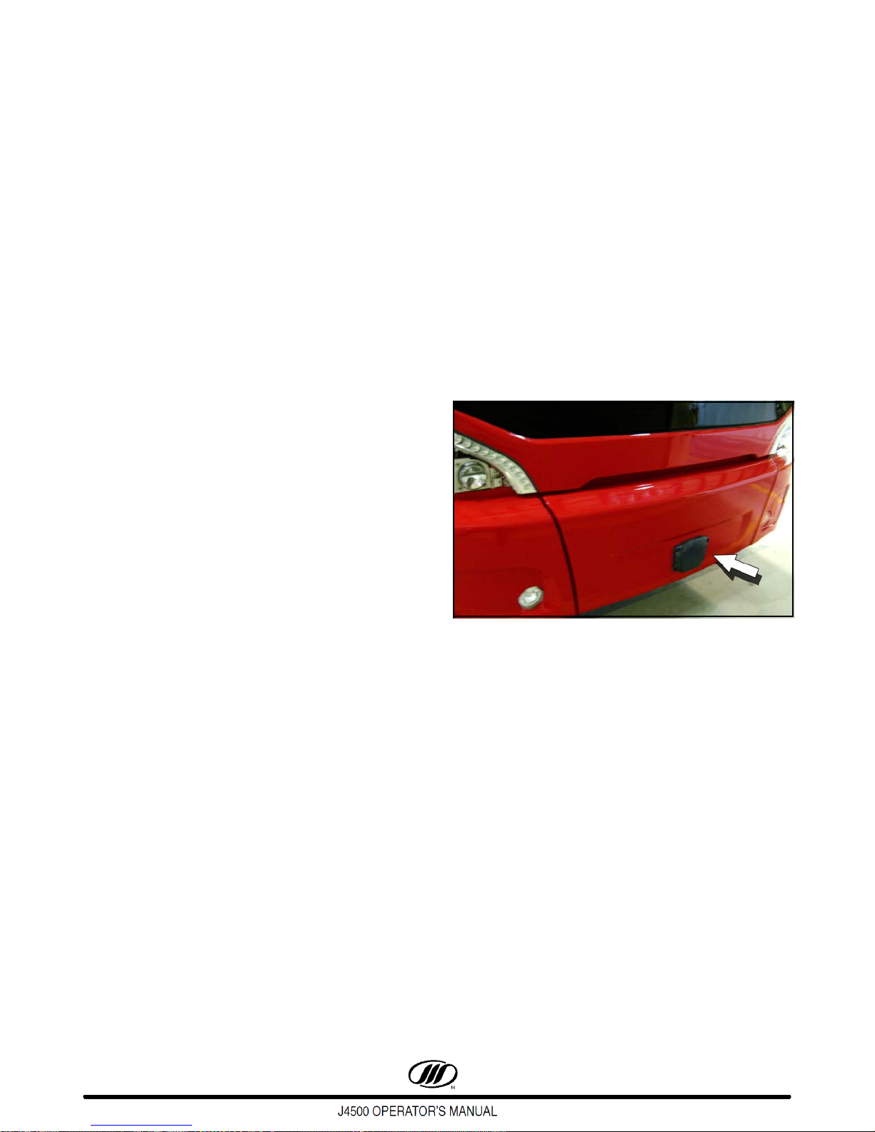
Front Bumper Radar Sensor
The sensor relaying information to the DIU is
located on the front bumper of the coach.
Solid Blue LEDs
If the operator doesn't take action within 15
seconds, the system will shut off and a DTC
(Diagnostic Trouble Code) will be generated. All
intervention features of the system will remain off until
the next ignition cycle. If the operator does intervene
within the 15 seconds, the system will remain
unavailable for 20 minutes. After 20 minutes the
displayed ACB Braking Overuse message will
disappear and the blue LED will turn off.
Figure 23. Radar Sensor
Radar sensor inspection for obstruction/
damage must be monitored routinely.
June 201624
4 - STEERING COLUMN & FLOOR-MOUNTED CONTROLS
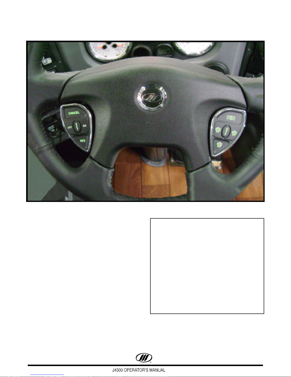
Figure 24. Steering Wheel
STEERING COLUMN
Ensure that the column is firmly locked
before driving. Do not adjust the steering
column while driving; steering control could
be lost.
The tilt and telescoping steering column has a
molded polyurethane steering wheel with fingertip
cruise and engine brake controls.
The tilt/telescoping control lever is on the LH side
of the steering column. Pull on the adjustment lever
and tilt the steering wheel to the desired position. Push
on the adjustment lever and raise or lower the
assembly as necessary. Release the lever to lock.
Ensure that the column is securely latched.
Figure 25. Tilt / Telescoping Control Lever
25June 2016

“SMART STICK” CONTROLS
1
2
3
4
The “Smart Stick”, on the LH side of the steering
column, controls the turn signals, air horn,
headlamp dimmer, windshield washer and
windshield wipers.
Turn Signals
Move the lever up for right turns, and down for left
turns. The corresponding telltale will flash.
Air Horn
Press the button on the end of the turn signal lever
to activate the air horn.
Headlamp Dimmer
Pull the turn signal lever forward and release it to
change from one setting to another. The HIGH
BEAM telltale lights when the headlights are on
high beam.
Windshield Washers
Push the sleeve towards the steering column.
Activating the washer turns the wipers ON for four
seconds on low speed.
Windshield Wipers
There are four rotary positions that operate the
wipers: OFF, intermittent, low speed and high
speed.
Figure 26. Smart Stick Features
1. Windshield Washer
2. Windshield Washer
3. Turn Signals
4. Air Horn
June 201626

CRUISE CONTROL
Do not use cruise control in heavy traffic, on
icy roads or in any other driving condition
that does not permit a constant speed.
Setting Vehicle Speed
Press the ON switch to turn on the cruise control.
Accelerate to the desired speed, press the Set
switch, then release the accelerator pedal. The
CRUISE ENABLED telltale on the RH cluster stays
on until the cruise control is turned off.
Cruise control will not operate under 20 mph
(32 km/h).
NOTE: When automatic operation is canceled,
RES may be used to return to cruise control.
Increasing Set Speed
1. Press and hold the RES switch until the desired
speed is reached, or,
2. Press the accelerator pedal until the desired
speed is reached, then press and release the
switch.
SET
When driving with cruise control, speed may
be increased (for passing, etc.) by pressing
the accelerator in the usual way. Releasing
the accelerator returns the coach to the set
speed
.
Decreasing Set Speed
1. Press and hold the SET switch until the desired
speed is reached, or,
2. Lightly press the brake to disengage the
system. Allow the vehicle to coast to the desired
speed, then press and release the
SET switch.
Figure 27. Switch Pod
ENGINE BRAKE
The engine brake controls are mounted on the RH
side of the steering wheel.
The four controls are: OFF, LOW, MEDIUM and
HIGH.
The transmission may be shifted in the
normal way without disengaging the cruise
control.
Canceling the Set Speed
1. Press the OFF switch or the CANCEL button, or,
2. Make a slight brake application.
Figure 28. Switch Pod
The button located at the top of the RH control
features a “courtesy light” that momentary flashes
the coach marker lights to acknowledge passing
vehicles.
27June 2016
 Loading...