

MCi C, C1 Operation Manual
www.mcisolutions.ca
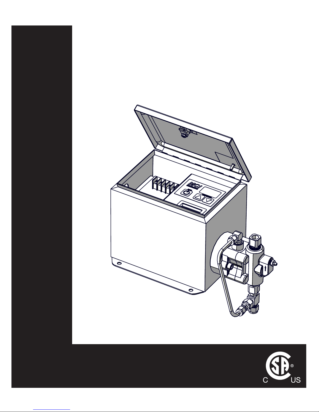
OPERATIONS MANUAL
MODEL C1 ELECTRIC CHEMICAL
INJECTION SYSTEM
C SERIES

GENERAL SAFETY
ii
www.mcisolutions.ca
Table Of Contents
General Safety 1
Symbol Usage . . . . . . . . . . . . . . . . . . . . . . . . . . . . . . . . . . . . . . . . . . . . . . . . 1
Proper Use . . . . . . . . . . . . . . . . . . . . . . . . . . . . . . . . . . . . . . . . . . . . . . . . . .2
Sources of Danger . . . . . . . . . . . . . . . . . . . . . . . . . . . . . . . . . . . . . . . . . . . . .2
Authorized Operators . . . . . . . . . . . . . . . . . . . . . . . . . . . . . . . . . . . . . . . . . . . 3
Personal Protective Equipment . . . . . . . . . . . . . . . . . . . . . . . . . . . . . . . . . . . . . 4
In Case of Emergency . . . . . . . . . . . . . . . . . . . . . . . . . . . . . . . . . . . . . . . . . . .4
System Specications 5
Electric Drive Dimensions . . . . . . . . . . . . . . . . . . . . . . . . . . . . . . . . . . . . . . . . . 5
Mounting Dimensions . . . . . . . . . . . . . . . . . . . . . . . . . . . . . . . . . . . . . . . . . . . 5
Static Head Requirements . . . . . . . . . . . . . . . . . . . . . . . . . . . . . . . . . . . . . . . . 6
Electrical Specications . . . . . . . . . . . . . . . . . . . . . . . . . . . . . . . . . . . . . . . . . . 6
General Specications . . . . . . . . . . . . . . . . . . . . . . . . . . . . . . . . . . . . . . . . . . . 7
Output Performance . . . . . . . . . . . . . . . . . . . . . . . . . . . . . . . . . . . . . . . . . . . . 7
Installation 8
General . . . . . . . . . . . . . . . . . . . . . . . . . . . . . . . . . . . . . . . . . . . . . . . . . . . .8
Standard Package Contents . . . . . . . . . . . . . . . . . . . . . . . . . . . . . . . . . . . . . . .8
Plumbing Overview . . . . . . . . . . . . . . . . . . . . . . . . . . . . . . . . . . . . . . . . . . . .9
Power Supply . . . . . . . . . . . . . . . . . . . . . . . . . . . . . . . . . . . . . . . . . . . . . . . .12
System Startup . . . . . . . . . . . . . . . . . . . . . . . . . . . . . . . . . . . . . . . . . . . . . . .14
Operating Instructions 15
Controller Overview . . . . . . . . . . . . . . . . . . . . . . . . . . . . . . . . . . . . . . . . . . . . 15
Setting Flow Rate . . . . . . . . . . . . . . . . . . . . . . . . . . . . . . . . . . . . . . . . . . . . . . 16
Troubleshooting 18
Bill of Materials 21
Material Codes . . . . . . . . . . . . . . . . . . . . . . . . . . . . . . . . . . . . . . . . . . . . . . . . 21
General System Detail View . . . . . . . . . . . . . . . . . . . . . . . . . . . . . . . . . . . . . . .22
FMT Fluid End . . . . . . . . . . . . . . . . . . . . . . . . . . . . . . . . . . . . . . . . . . . . . . . . 23
Plunger Seals . . . . . . . . . . . . . . . . . . . . . . . . . . . . . . . . . . . . . . . . . . . . . . . . . 24
In-line Filter . . . . . . . . . . . . . . . . . . . . . . . . . . . . . . . . . . . . . . . . . . . . . . . . .25
Pressure Relief Valve . . . . . . . . . . . . . . . . . . . . . . . . . . . . . . . . . . . . . . . . . . . . 25
Maintenance 27
Preventative Maintenance Schedule . . . . . . . . . . . . . . . . . . . . . . . . . . . . . . . . . . 27
Lubrication Details . . . . . . . . . . . . . . . . . . . . . . . . . . . . . . . . . . . . . . . . . . . . . 28
Plunger Seal Maintenance Procedure . . . . . . . . . . . . . . . . . . . . . . . . . . . . . . . . . 28
Check Valve Maintenance . . . . . . . . . . . . . . . . . . . . . . . . . . . . . . . . . . . . . . . . . 35
Limited Warranty 38
Maintenance Log 39
1
www.mcisolutions.ca
The C1 Electric Chemical Injection System has been subjected to a safety test and quality acceptance inspection. Please ensure all safety instructions in this manual are clearly understood. Misuse or incorrect
operation of the System may cause serious injury or death
Only properly and trained personnel should be involved in the setting up, putting into service, inspecting, servicing and repairing of this equipment.
Read and understand all instructions. Failure to follow the Dangers,
Cautions and Warnings contained in this owners manual may result in electric
shock, re, serious bodily injury or death
CAUTION!
General Safety
Symbol Usage
Designates an imminent danger. In case of non-observance of this information, death or severe injuries are an imminent risk
Designates possibility of a dangerous situation. In case of non-observance of this information, death or severe injuries can occur
Designates areas where the potential for severe crush injury exists.
These crush injuries can result in serious bodily injury
Electrical Shock Hazard Warning indicates a potential injury hazard that
can result in serious bodily injury or death
Designates important user tips and other useful information
Designates important installation information that if not followed could
cause System failure
DANGER!
CAUTION!
GENERAL SAFETY
2
www.mcisolutions.ca
NOTICE TO INSTALLER: This manual must be left with the owner/operator of the System and kept
for future reference
Proper Use
This System uses a reciprocating positive displacement pump. It serves the purpose of conveying and
circulating liquids. The System and these operating instructions are intended for commercial use exclusively
Severe skin injury can result from dangerous media used with this System.
(i.e. Aggressive, toxic and caustic media)
Unsuitable media can damage the pump and then escape into the surrounding area
If you intend to use dangerous media, the materials used for the pump parts
must be designed and compatible for this use
ANY form of liability on the part of the manufacturer shall be null and
void if the System has been modied by others without authorization
from MCI
When replacing parts in the System, use only spare parts approved by MCI. (Refer to the Bill of Materials
section in this manual for more information )
Always Disconnect power to the System before performing ANY maintenance
or repair activities
Sources of Danger
The System has been manufactured in compliance with CSA standards and complies with all applicable
safety requirements
Although most safety risks have been reduced through design and construction measures, residual risks
(i.e. explosive atmospheres, electrical, mechanical or thermal) cannot be excluded entirely during either
transport, maintenance and repair work, or regular operation
CAUTION!
CAUTION!
DANGER!
3
www.mcisolutions.ca
Authorized Operators
Only persons who have been properly authorized and trained by MCI or its authorized agent may work
on or with this equipment
The owner must:
■ Clearly dene and ensure the observance of the responsibilities for all tasks performed in con-
nection with the System
■ Make this manual accessible to all operations sta
■ Make sure operations have read and understood all operating instruction
For Extra copies of this manual or for more information please visit us online
at: www.mcisolutions.ca
Or, Scan the following QR code with your smart phone for a direct link to
digital copies of all MCI Operation Manauls:
Maintenance, upkeep and electrical tasks should only be performed by
technically competent, trained and/or qualied personnel
Technically competent people, trained and qualied personnel are dened as individuals who:
■ Possess sucient knowledge in a specic eld based on their specialized training and experi-
ence; and
■ Are familiar with all applicable work safety and accident prevention regulations (i.e. lock-out or
tag-out safety procedures)
CAUTION!
GENERAL SAFETY
4
www.mcisolutions.ca
Personal Protective Equipment
Wear appropriate protective equipment especially when performing any
maintenance, inspection or cleaning task on the System
Oils, Lubricants and cleaning agents can cause skin reactions and irritation.
Avoid skin contact with all chemical used in connection with the System
In Case of Emergency
In case of Emergency originating from the System or from conditions in the surrounding area, the System must be switched o immediately
The System cannot be put back into operation until the emergency has been identied and corrected.
Ensure corrective actions are taken to prevent future occurrence
In case of res, use only suitable re-extinguishing agents
If the instructions in this manual are not adhered to or are inadequately
adhered to , the warranty shall become null and void and the CSA declaration of conformity shall immediately cease to be valid
MCI makes no other warranty, including without limitation, any warranties or merchantability or of tness
for a particular purpose, whether express or implied. MCI will not be liable under any circumstances
whatsoever to the purchaser for any damages relating to loss of production, loss of product, environment
damage, or any incidental, consequential, special or punitive damages regardless of whether arising in
contract, strict liability, other tort or otherwise. The exclusive remedy of the purchaser for any and all
losses, injuries or damages resulting from the sale, use or handling of any product whether in contract,
warranty tort, negligence, strict liability or otherwise, will not exceed the purchase price paid, or at MCI’s
sole election, the repair or replacement of the product
CAUTION!
CAUTION!
5
www.mcisolutions.ca
System Specications
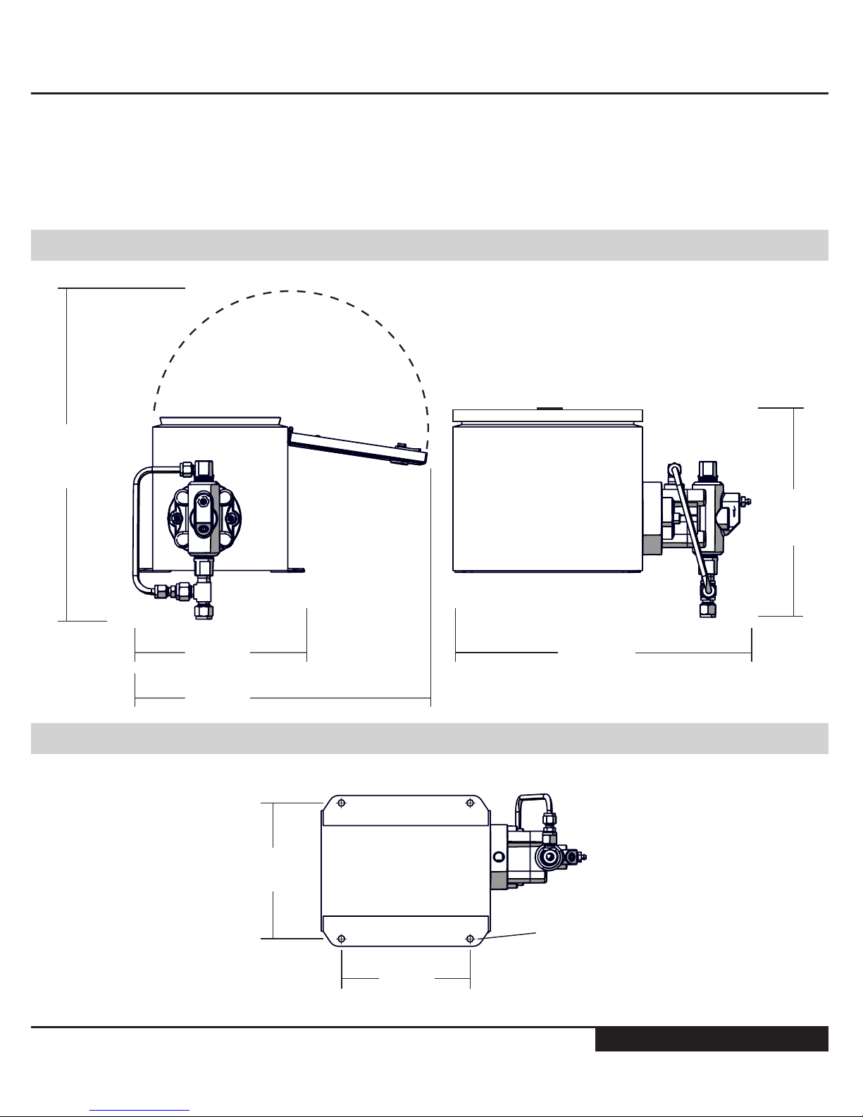
Electric Drive Dimensions
335 mm
(13.2 in)
370 mm
(14.5 in)
190 mm
(7.5 in)
330 mm
(13.0 in)
234 mm
(9.2 in)
LID CLOSED
Mounting Dimensions
173 mm
(6.8 in)
C/L TO C/L
163 mm
(6.4 in)
C/L TO C/L
7.9 mm
(0.313 in)
Diam. (x4)

GENERAL SAFETY
6
www.mcisolutions.ca
Static Head Requirements
MINIMUM (CL TO CL)
305 mm
(12.0 in)
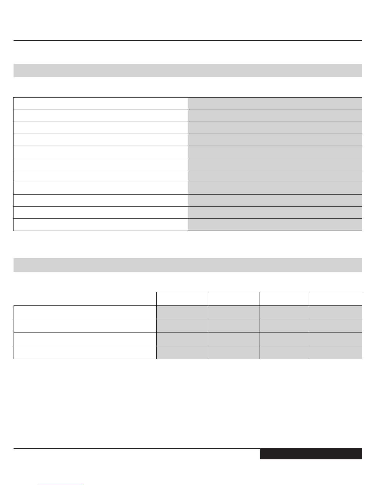
Electrical Specications
Electrical Rating 24V DC
Classication CSA CLASS 1 DIVISION 2
Enclosure Rating Nema 3R
Temperature Code T4A
Motor Type 4 Pole Stepper Motor, 1.8 Degree Step
Inrush Current 950 (mA)
Avg. Power Consumption 450 (mA) MAX
Reverse Polarity Protection Standard
Analog Input [4-20 mA] Optional Upgrade [Innite Scale adjustments and
remote On/O capability]
Integrated Low Voltage Disconnect Standard [custoM set points AvAilAble]
7
www.mcisolutions.ca
General Specications
N-seal Leak Containment Adaptor Standard
Variable Speed Controller Electronic/ MOSFET
Electro-mechanical contactors / Relays N/A
Electro-mechanical Timers N/A
Dip Switch N/A
Fluid End Carbon Steel [316L S.S. Upgrade available]
Fluid End Suction and Discharge Seals OMX Fluoroelastomer®
Secondary Containment Static Seals Teon®
Seal Kit Dynamic Seals UHMW Polyethylene c/w Stainless Steel spring.
Plunger Material Tungsten Carbide
Operating Temperature -40 to +40 [oC]
Output Performance
1/4" Plunger 3/8" Plunger 1/2" Plunger 11/16" Plunger
Maximum Displacement Pressure [Psi] 3000 1500 750 400
Maximum Displacment Pressure [kPa] 20684 10342 5171 2758
Maximum Output Volume [Litres/day] 12 29 52 104
Minimum Output Volume [Litres/Day] 0.12 0.26 0.46 0.86
GENERAL SAFETY
8
www.mcisolutions.ca
Installation
General
Congratulations. You have chosen the nest, most accurate electrically powered chemical injection System available. Before Installation, please inspect the pump carefully for any possible in-transit damage. If the pump appears damaged, call your local distributor or call MCI customer service direct at
+1.888.263.4565
Please ensure you have fully read and understood the general safety
section of this manual before proceeding with the System installation
The System is CSA approved for use in Class 1 Division 2 areas. It is the
responsibility of the owner to determine the classication of the area
where the System is to be installed
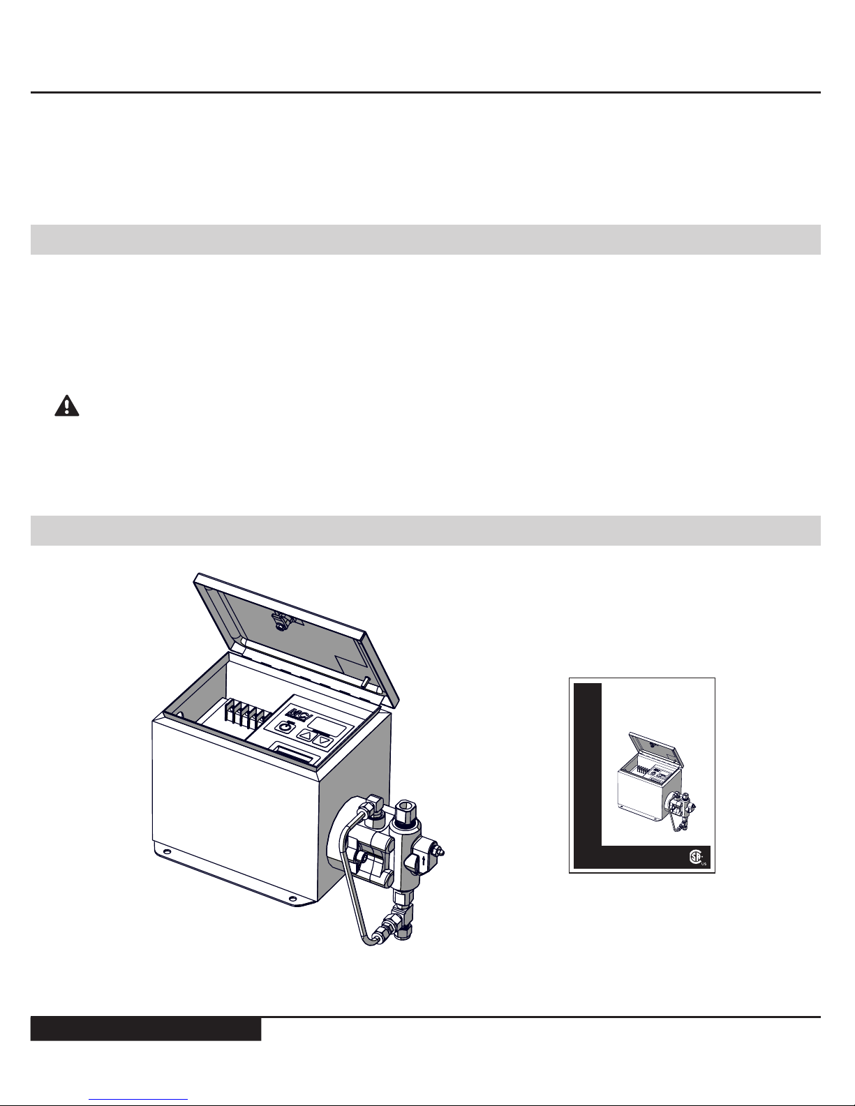
Standard Package Contents
C1 Electric Drive (x1)
Manual (x1)
OPERATIONS MANUAL
MODEL C1 ELECTRIC CHEMICAL
INJECTION SYSTEM
C SERIES
www.mcisolutions.ca
CAUTION!
9
www.mcisolutions.ca
The System is to be mounted securely in a safe location that satises the classication requirements.
The Systems Fluid End (Pump) must be oriented in a vertical position for proper check valve operation
Allow a minimum distance of 12 in. from the center line of the pump head to the lowest point on the
chemical storage container bulkhead to ensure adequate [positive] static head pressure is available. The
System relies on a positive suction pressure to run correctly [grAphic eXplAnAtion shown on pAge 6]
The membrane switch panel is covered with a clear plastic lm, remove prior to operating the System
Plumbing Overview
Only properly qualied and trained personnel should be involved in the
setting up , putting into service, inspecting, servicing and repairing of the
plumbing for the uid end
Ensure all National, Provincial/State and local codes are followed when plumbing equipment. Failure to follow these codes can result in serious bodily injury
or death
The following plumbing suggestions are examples of typical installations only and may not be the best
suited method for your custom installation
Ensure all process valves are closed prior to disconnecting or re-installing any chemical injection System
To avoid over-pressuring chemical discharge lines MCI requires placing a properly tested and calibrated
Pressure Relief valve (PRV) between the discharge port of the uid end and the process injection point.
The set point must not exceed the pumps maximum discharge pressure [MAXiMuM dischArge pressures cAn be
found in the 'systeM specificAtions' section under 'output perforMAnce']
Failure to add a CERTIFIED and CALIBRATED Pressure Relief Valve (PRV)
to the System is inherently unsafe. It can cause catastrophic System
damage and voids all System warranty. MCI is not responsible for any
damage caused by exceeding maximum System pressure. MCI oers
complete PRV solutions for all Systems. Please contact customer service
for latest pricing and availability: +1.888.263.4565
CAUTION!
GENERAL SAFETY
10
www.mcisolutions.ca
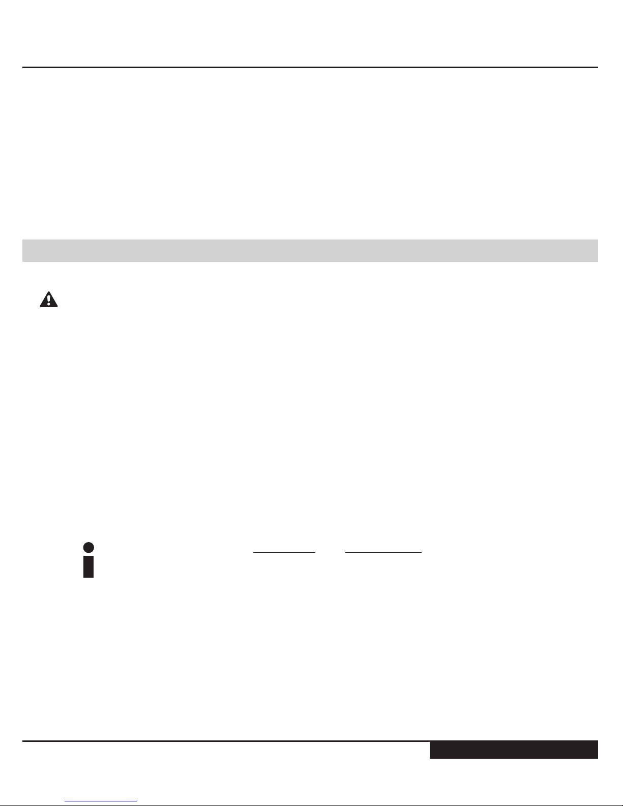
Standard Connection Points
Removing foreign debris from suction lines and chemical storage containers
will greatly extend the life of all dynamic seals used in the System. It is highly
recommended to use a pre-suction in-line lter on all Systems. MCI oers
in-line lter kits for all pump models. Please contact customer service for the
latest pricing and availability: +1.888.263.4565
Secondary Containment Line
1. Fluid End Discharge Point - 1/4” Fem. NPT
2. Pressure Transducer Port - 1/8" NPT
3. Fluid End Suction Point - 3/8” Tube
3
1
2
1. Secondary containment line - 1/4” Tube
1
11
www.mcisolutions.ca
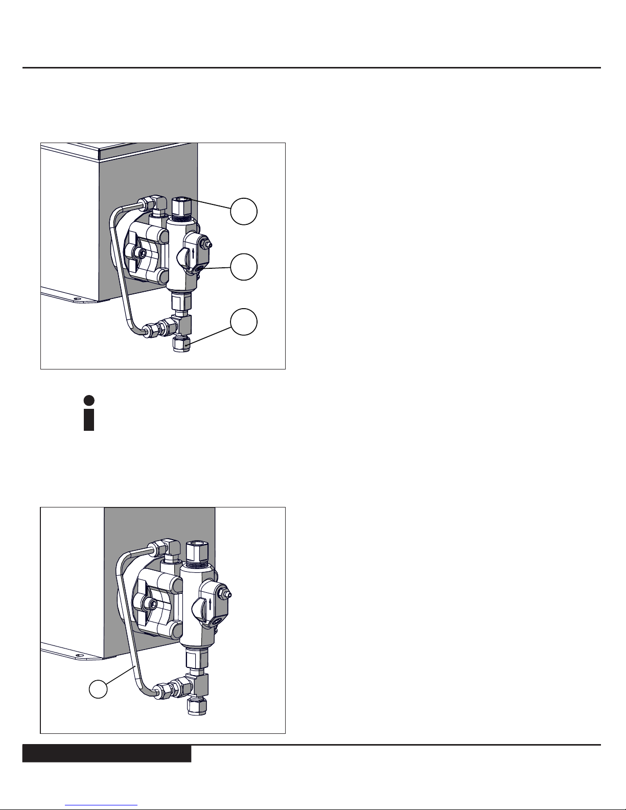
Pressure Relief Valve Tie-In [TYPICAL ARRANGEMENT SHOWN]
Pressure relief valve kits are available direct from MCI. Kits include all tubing
[where applicable] and ttings required to complete the installation. Contact
customer service for more information: +1.888.263.4565
Suggested in-Line Filter [TYPICAL ARRANGEMENT SHOWN]
1. Pressure Relief Valve
2. Male Connector - 1/4” NPT x 3/8” Tube
3. Run Tee - 1/4” NPT [Main Discharge Point]
4. Stainless Steel Tubing [.035] - 3/8”
5. Tube Connector - 3/8”
6. Union Tee - 3/8”
6
5
4
3
1
2
1. In-line lter - 440 Micron
2. Tube connector - 3/8”
12
GENERAL SAFETY
12
www.mcisolutions.ca
In-line lter assemblies are available direct from MCI. Kits include all tubing
[where applicable] and ttings required to complete the installation. Contact
customer service for more information: +1.888.263.4565
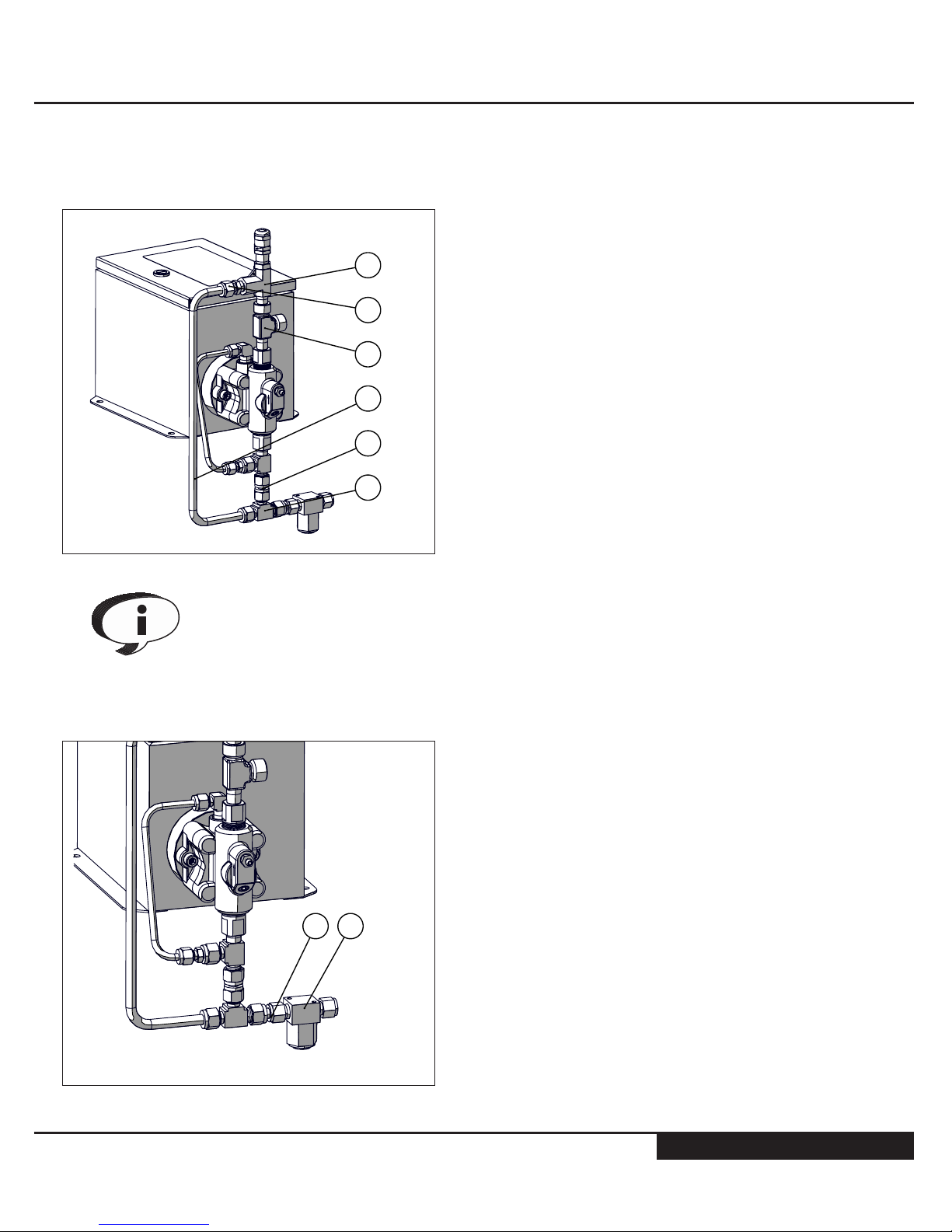
The 1/4” NPT drain port shown [Arrow] is a general
System drain port [DO NOT PLUG OFF] This port
must remain open or plumbed to a designated
containment area
Without routine maintenance it is possible for seal
bypass from the low pressure side to exit this port.
Ensure proper containment areas are in place and
suggested routine seal maintenance procedures
are followed to prevent spills
Power Supply
When wiring the System follow cable orientation labels found on the inside of
the enclosure lid. Failure to orientate wiring properly may result in damage to
the on-board electronics and could cause serious bodily injury or death
To protect the System and associated components the pump box must be
connected to ground. All electrical connections must satisfy National, Provincial/State and local electrical codes
SYSTEM CAN START AUTOMATICALLY - Before connecting power to the
control board ensure that you and all tools used in setup are clear of moving
parts, serious bodily injuries can occur
When connecting cables to the control module ensure keyed connections
are tight. Loose connections can cause arcing and erosion which destroy the
integrity of the connections
 Loading...