

McFarlane HDL-1126, HDL-1128, HDL-1132, HDL-1134, HDL-1136 Operator's Manual And Parts List
...
OPERATOR’S MANUAL
AND
PARTS LISTING
FOR THE
HDL-1100 Series
version: 11-16 (12366)
starting at serial number 20484
Before assembling or operating this unit, READ THIS MANUAL THOROUGHLY. To obtain the best
performance of the unit, familiarize yourself with each component and adjustment. Store this manual
where it can be readily available for future reference. In the event that the harrow or any part of the
unit should be sold, be sure that the new owner receives a copy of this manual for their reference.
1330 Dallas Street ∙ PO Box 100 ∙ Sauk City WI 53583
Phone (608) 643-3322 ∙ Toll Free (888) 627-8569 ∙ Fax (608) 643-3976
TOTHEOWNERANDOPERATORS
www.flexharrow.com

TABLE OF CONTENTS
INTRODUCTION ...............................................................................................................3
LIMITED WARRANTY .....................................................................................................3
SAFETY ..............................................................................................................................4
CONTACT INFORMATION ..............................................................................................5
LIGHTING AND MARKING .............................................................................................6
SAFETY SIGN CARE .................................................................................................. 6 - 7
TIRE SAFETY.....................................................................................................................7
BEFORE OPERATION................................................................................................. 7 - 8
DURING OPERATION ......................................................................................................8
FOLLOWING OPERATION ..............................................................................................9
HIGHWAY AND TRANSPORT OPERATIONS ...................................................... 9 - 10
PERFORMING MAINTENANCE ...................................................................................10
MAINTENANCE AND SERVICE SCHEDULE .............................................................11
OPERATING SUGGESTIONS.........................................................................................11
ASSEMBLY SUGGESTIONS ..........................................................................................12
ASSEMBLY INSTRUCTIONS ................................................................................13 – 33
FINAL ADJUSTMENTS ..................................................................................................34
TROUBLESHOOTING ................................................................................. APPENDIX A
BOLT & TIRE SPECIFICATIONS .............................................................. APPENDIX A
PARTS DIAGRAMS AND LISTS ............................................................... APPENDIX B
LAYOUT DIAGRAMS ................................................................................. APPENDIX C
WARRANTY REGISTRATION FORM ....................................................... LAST PAGE
2

INTRODUCTION
Thank you for purchasing your new McFarlane transport cart and harrow sections. We know that
you will get many years of dependable service from this modernly designed unit.
You may have had a particular application in mind when you purchased this unit. There are
actually many uses for the McFarlane harrow including incorporation of herbicides and pesticides,
leveling and smoothing tilled soil, and covering of broadcast seeds. Contact your dealer if you
would like more information or have questions concerning these or other applications.
LIMITED WARRANTY
FULL ONE - YEAR WARRANTY OF
HDL-1100 Series
If within one year from the date of purchase, this transport cart and/or its accompanying harrow
sections fail due to defect in material or workmanship, McFarlane Mfg. Co., Inc. will repair it, free
of charge.
Warranty service is available by simply contacting the nearest McFarlane dealership throughout
the United States or Canada.
This warranty applies only while this product is used in the United States or Canada.
This warranty gives you specific legal rights, and you may have other rights which vary from state
to state.
McFarlane Mfg. Co., Inc., Sauk City, Wisconsin 53583
3

SAFETY
TAKE NOTE! THIS SAFETY ALERT SYMBOL FOUND THROUGHOUT THIS MANUAL
IS USED TO CALL ATTENTION TO INSTRUCTIONS INVOLVING YOUR PERSONAL
SAFETY AND THE SAFETY OF OTHERS. FAILURE TO FOLLOW THESE
INSTRUCTIONS CAN RESULT IN INJURY OR DEATH.
THIS SYMBOL MEANS
ATTENTION!
BECOME ALERT!
YOUR SAFETY IS INVOLVED!
SIGNAL WORDS:
Note the use of the signal words DANGER, WARNING, and CAUTION with the safety
messages. The appropriate signal word for each has been selected using the following guidelines:
DANGER: Indicates an imminently hazardous situation that, if not avoided, will result in death
or serious injury.
WARNING: Indicates a potentially hazardous situation that, if not avoided, could result in death
or serious injury.
CAUTION: Indicates a potentially hazardous situation that, if not avoided, may result in minor
or moderate injury.
4

CONTACT INFORMATION
If you have questions not answered in this manual, require additional copies, or the manual is
damaged, please contact your local dealer or:
McFarlane Mfg. Co., Inc.
1330 Dallas Street
P.O. Box 100
Sauk City, WI 53583
PHONE: (608) 643-3322
TOLL FREE: (888) 627-8569
FAX: (608) 643-3976
INTERNET: www.flexharrow.com
EMAIL: info@flexharrow.com
5

SAFETY FIRST!
Equipment Safety Guidelines
Safety of the operator is one of the main concerns in designing and developing a new piece of
equipment. Designers and manufacturers build in as many safety features as possible. However,
every year many accidents occur which could have been avoided by a few seconds of thought and
a more careful approach to handling equipment. You, the operator, can avoid many accidents by
observing the following precautions. To avoid personal injury, study the following precautions
and insist that those working with you, or for you, follow them.
Replace any CAUTION, WARNING, DANGER, or instruction safety decal that is not readable or
missing.
Do not attempt to operate this equipment under the influence of drugs or alcohol.
Review the safety instructions with all users annually.
This equipment is dangerous to children and persons unfamiliar with its operation. The operator
should be a responsible adult familiar with farm machinery and trained in this equipment’s
operations. Do not allow persons to operate or assemble this unit until they have read this
manual and have developed a thorough understanding of the safety precautions and of how
it works.
To prevent injury, use a tractor equipped with a Roll Over Protective System (ROPS). Do not
paint over, remove, or deface any safety signs or warning decals on your equipment. Observe all
safety signs and practice the instructions on them.
Never exceed the limits of the transport cart or the harrows. If their ability to do a job, or to do so
safely, is in question - DO NOT TRY IT.
Lighting and Marking
It is the responsibility of the customer to know the lighting and marking requirements of the local
highway authorities and to install and maintain the equipment to provide compliance with the
regulations. Add extra lights when transporting at night or during periods of limited visibility.
Safety Sign Care
Keep safety signs clean and legible at all times.
Replace safety signs that are missing or have become illegible.
Replacement parts that display a safety sign should display the same sign.
Safety signs are available from your Distributor, Dealer Parts Department, or the factory.
How to Install Safety Signs:
6

Be sure that the installation area is clean and dry.
Decide on the exact position before you remove the backing paper.
Tire Safety
Failure to follow proper procedures when mounting a tire on a wheel or rim can produce an
explosion which may result in serious injury or death.
Do not attempt to mount tires unless you have the proper equipment and experience to do the
job.
Inflating or servicing tires can be dangerous. Whenever possible, trained personnel should be
called to service and/or mount tires.
Always order and install tires and wheels with appropriate capacity to meet or exceed the
weight of the unit. Be sure to inflate tires to tire manufacturer’s specifications
Tires that are provided by the manufacturer are designed for speeds LESS THAN 20mph. Do
Not exceed or tire failure will occur.
Remember:
Your best assurance against accidents is a careful and responsible operator. If there is any
portion of this manual or function you do not understand, contact your local authorized
dealer or the manufacturer.
Before Operation:
Carefully study and understand this manual.
Do not wear loose fitting clothing which may catch in moving parts.
Always wear protective clothing and substantial shoes.
It is recommended that suitable protective hearing and (eye protection) sight protectors be
worn.
Keep wheel lug nuts or bolts tightened.
Assure that the tires are inflated evenly.
Give the unit a visual inspection for any loose bolts, worn parts, or cracked welds, and make
necessary repairs. Follow the maintenance safety instructions included in this manual.
Before using the hydraulics on the cart, be sure all fittings and connections are tight.
Be sure that there are no tools lying on the unit.
Make sure that the area is clear of children, animals, and other obstacles before using.
Don’t hurry the learning process or take the unit for granted. Ease into it and become familiar
with your new equipment. Practice operation of your new unit. Completely familiarize
yourself and other operators with its operation before using.
7

Securely attach to towing unit. Use a high strength, appropriately sized hitch pin with a
mechanical retainer and attach safety chain.
Do not allow anyone to stand between the tongue or hitch and the towing vehicle when
backing up to the equipment.
During Operation:
SAFETY CHAIN - If equipment is going to be transported on a public highway, a safety chain
should be obtained and installed. Always follow state and local regulations regarding a safety
chain when towing farm equipment on a public highway. Be sure to check with local law
enforcement agencies for your own particular regulations. Only a safety chain (not an elastic
or nylon/plastic tow strap) should be used to retain the connection between the towing and
towed machines in the event of separation of the primary attaching system.
Install the safety chain by crossing the chains under the tongue and secure to the draw bar cage
or hitch or bumper frame.
Beware of bystanders, particularly children! Always look around to make sure that it is safe
to start the engine of the towing vehicle or move the unit. This is particularly important with
higher noise levels and quiet cabs, as you may not hear people shouting.
NO PASSENGERS ALLOWED - Do not carry passengers anywhere on, or in, the tractor or
equipment, except as required for operation.
Keep hands and clothing clear of moving parts.
Do not clean, lubricate, or adjust your equipment while it is moving.
When altering operation, even periodically, set the tractor or towing vehicle brakes, shut off
the engine, and remove the ignition key.
Do not operate the hydraulic cylinders without the flow restrictors installed; the free falling
harrow sections may cause serious injury.
Pick the smoothest and flattest possible route when transporting across fields. Avoid the edges
of ditches or gullies and steep hillsides.
Periodically clear the equipment of brush, twigs, or other materials to prevent buildup of dry
combustible materials.
Maneuver the tractor or towing vehicle at safe speeds.
Avoid overhead wires or other obstacles. Contact with overhead lines could cause serious
injury or death.
Allow for unit length when making turns.
Do not walk or work under raised wings unless securely positioned in wing rests.
Keep all bystanders, pets, and livestock clear of the work area, particularly when raising or
lowering harrow sections.
Operate the towing vehicle from the operator’s seat only.
As a precaution, always recheck the hardware on equipment periodically. Correct all
problems. Follow the maintenance safety procedures.
8

Following Operation:
When disconnecting, stop the tractor or towing vehicle, set the brakes, secure the wings in the
wing rests, relieve hydraulic fluid pressure, shut off the engine and remove the ignition keys.
Make sure all jack and support stands are in place before removing hitch pins.
Store the unit in an area away from human activity on a hard level surface.
Do not park equipment where it will be exposed to livestock for long periods of time. Damage
and livestock injury could result.
Do not permit children to play on or around the stored unit.
Highway and Transport Operations:
Make sure all transport lock provisions are in place and jack/parking stands are in their storage
position before transporting the unit.
Adopt safe driving practices:
– Keep the brake pedals latched together at all times. NEVER USE INDEPENDENT
BRAKING WITH MACHINE IN TOW AS LOSS OF CONTROL AND/OR UPSET
OF UNIT MAY RESULT.
– Always drive at a safe speed relative to local conditions and ensure that your speed is low
enough for an emergency stop to be safe and secure. Keep speed to a minimum.
– Reduce speed prior to turns to avoid the risk of overturning.
– Avoid sudden uphill turns on steep slopes.
– Always keep the tractor or towing vehicle in gear to provide engine braking when going
downhill. Do not coast.
– Do not drink and drive!
Comply with state and local laws governing highway safety and movement of farm machinery
on public roads.
Use approved accessory lighting flags and necessary warning devices to protect operators of
other vehicles on the highway during daylight and nighttime transport. Various safety lights
and devices are available from your dealer.
The use of flashing amber lights is acceptable in most localities. However, some localities
prohibit their use. Local laws should be checked for all highway lighting and marking
requirements.
When driving the tractor and equipment on the road or highway under 20 mph at night or
driving during the day, use flashing amber warning lights and a slow moving vehicle (SMV)
identification emblem.
Remember, tires supplied by the manufacturer are designed to operate LESS THAN 20mph.
Do Not exceed or tire failure will occur.
Be a safe and courteous driver. Always yield to oncoming traffic in all situations, including
narrow bridges, intersections, etc. Plan your route to avoid heavy traffic.
9

Be observant of bridge loading ratings. Do not cross bridges rated lower than the gross weight
at which you are operating.
Watch for obstructions overhead and to the side while transporting.
Always operate equipment in a position to provide maximum visibility at all times. Make
allowances for increased length and weight of the equipment when making turns, stopping,
etc.
Performing Maintenance:
Good maintenance is your responsibility. Poor maintenance is an invitation to trouble.
Before working on this machine, stop the tractor or towing vehicle, set the brakes, lower into
field position, relieve the hydraulic fluid pressure, shut off the engine and remove the ignition
keys.
Always use safety support and block the wheels. When performing maintenance, never use a
jack to support the machine. Assist the jack with blocks or other adequate support.
Use extreme caution when making adjustments.
When disconnecting hydraulic lines, shut off hydraulic supply and relieve all pressure.
Never use hands to locate a hydraulic leak on attachments. Use a piece of cardboard or wood.
Hydraulic fluid escaping under pressure can penetrate the skin.
Openings in the skin and minor cuts are susceptible to infection from hydraulic fluid. If
injured by escaping hydraulic fluid, see a doctor at once. Gangrene can result. Without
immediate medical treatment, serious infection and reactions can occur.
When installing, replacing, or repairing hydraulic system cylinders or parts, make sure that the
entire system is charged and free of air before resuming operations. Failure to bleed the
system of all air can result in improper machine operation, causing severe injury.
After servicing, be sure all tools, parts, and service equipment are removed.
Never replace hex bolts with less than grade five bolts unless otherwise specified.
Where replacement parts are necessary for periodic maintenance and servicing, genuine
factory replacement parts must be used to restore your equipment to original specifications.
The manufacturer will not claim responsibility for damages as a result of the use of
unapproved parts and/or accessories.
If equipment has been altered in any way from original design, the manufacturer does not
accept any liability for injury or warranty.
10

MAINTENANCE AND SERVICE SCHEDULE
Prior to each use, check for loose bolts and replace lost or worn parts.
Grease hinge pins before each use when necessary.
Note: Clean grease fittings and replace those that are broken or missing.
Inspect and repack wheel bearings at the beginning of each year.
Remove dirt and debris from the harrow sections before storage.
Parts diagrams and listings for service and repair references may be found in appendix B.
OPERATING SUGGESTIONS
There are some important points to remember in order to obtain the best possible results from your
McFarlane harrow.
To maximize the harrow’s performance, it should be towed at speeds ranging from six to nine
(6 - 9) mph. This keeps the field debris moving through the harrow sections and avoids
clogging. The best results will be obtained after the paint has been scoured from the teeth.
Choose the angle of attack of the harrow teeth based on field conditions. For more
information see the section titled Angle of Attack.
Getting the unit ready for transport includes the following steps:
1. Rotate the harrow sections up.
2. Swing the wings forward and lock them into the wing rests.
Getting the unit ready for field use includes the following steps:
1. Unlock the wings from the wing rests and swing the wings out.
2. Rotate the harrow sections down.
Field Operation - while turning on the headlands (field ends) slow down and rotate the toolbar
up so the harrow sections begin to lift off the ground. Once traveling straight forward again,
lower the sections to the ground.
11

ASSEMBLY SUGGESTIONS
You will find the machine is easier to assemble if the set-up instructions are followed in the
order given in the manual.
Before beginning, sort the various bolt bags, hardware bags and hydraulic bags according to
what part of the unit that is being setup. Refer to the end of the parts listing in appendix B.
Only open the bag or bags that are required as the setup instructions are followed.
Whenever the terms “left” and “right” are used, it should be understood to mean when
standing behind and facing the unit. This is also known as the “driver’s left” and the “driver’s
right.”
The term “field position” refers to the position the harrows are in when the unit is being used
in the field - that is, with the wings out and the harrow sections down.
The term “transport position” refers to the position the harrows would be in when the unit is
being transported from place to place - that is, with the harrows up and the wings folded and
secured in the wing rests.
When assembling this unit, make sure that the parts are securely held before proceeding to the
next step.
Bolt torque specifications are given in appendix A.
The hydraulic cylinder and hose requirements are listed in the parts listing in appendix B. It is
not recommended that other size cylinders or hoses be substituted. Hoses are marked with the
part number near the ends.
A dual acting hydraulics supply is required. The unit is designed for the standard ASAE
pressure of 1500 psi.
Tire requirements are also listed in the parts listing in appendix B.
Layout diagrams for each unit may be found in appendix C. Mark the page with the diagram
that refers to your unit, it will be referred to periodically throughout the manual.
12

STEP - BY - STEP ASSEMBLY INSTRUCTIONS
Main Frame Assembly
1. Bolt the Axle Brackets to the main frame. You will have either the Standard Walking Axle or
the optional Tandem Axle assemblies. Both are shown in Figure 1. Use 5/8” x 2 1/4” bolts,
lock washers, and hex nuts. Note the orientation of the walking axle when installing this
option and be sure to include the Walking Axle Stop Tube Assemblies as shown.
2. Attach the hub with spindle to the Axle Bracket using 1/2” x 3 1/2” grade 8 bolts and lock
nuts.
3. Mount the wheels to the main frame Axle Brackets. Be sure the valve stem is pointing away
from the Axle Bracket.
4. Attach the jack to the Main Frame.
5. Assemble either a clevis hitch (Figure 2) or a pintle hitch (Figure 3) as required by the tractor
or towing vehicle. Note the opposite orientation of the base hitch for each hitch type. Attach
the hitch assembly to the A-frame with two 1” x 6 1/2” bolts and locking nuts.
Note: Parts have been provided to assemble a clevis hitch or a pintle hitch. Not all the included
parts will be needed to assemble either type of hitch. Be sure to store the extra parts in a safe
place; they will be needed if one requires the use of the other hitch type.
Note: For clarity purposes, the rest of the diagrams will be shown without the main axles and rims.
Figure 1
13
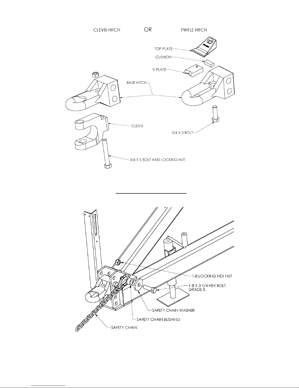
Figure 2 Figure 3
ATTACH SAFETY CHAIN
1. Attach the Safety Chain as shown in Figure 4.
Figure 4
14
Attach the Hitch Weights to the Main Frame
HDL-1124 only
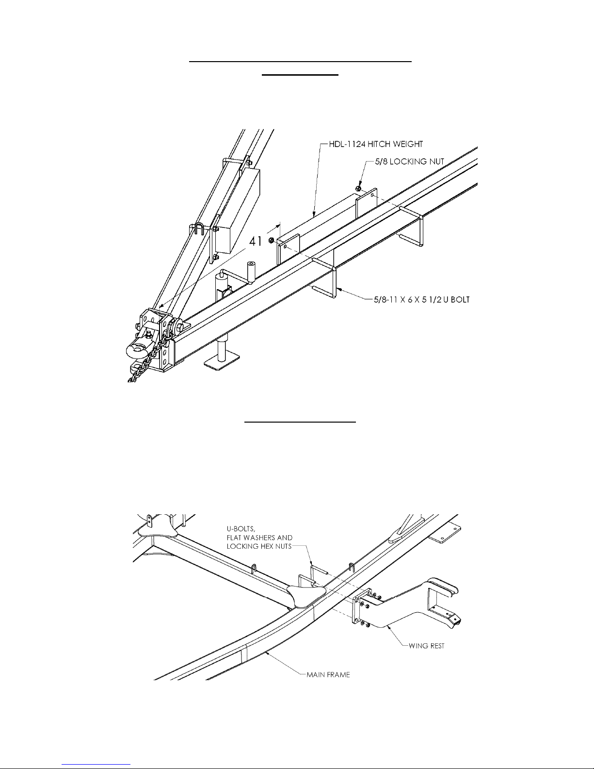
1. Attach the Hitch Weights to the Main Frame as shown in Figure 5. Dimension from front
of side tube to front of weight mount plate should be approximately 41. The weights must
be far enough back so that the jack can turn 90 degrees and pin into the field position.
Figure 5
Attach the Wing Rests
Attach the wing rests (12474) for HDL-1124 – 38, or (12477) for HDL-1140 – 60, to the
square frame. Refer to Figure 6. Use four (BU-5865) 5/8" x 6" x 5 1/2" U-Bolts for HDL1124 – 1138, four (BU-5887) 5/8” x 8” x 7 1/2” for HDL-1140 – 1150 and four (11969) 5/8” x
8” x 9 1/2” U-Bolts for HDL-1152 – 1160. Secure with flat washers, and lock nuts. Do not
tighten yet.
Figure 6
15
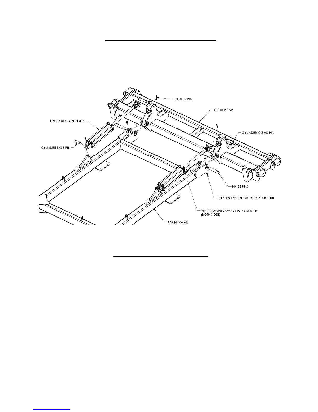
Attach the Center Bar to the Main Frame
Attach the center bar to the square frame. Refer to Figure 7. Use the (SPR-2712) 1 1/2” x 8 5/16”
hinge pins for HDL-1124 - 1138, (RT-2107) 1 1/2” x 9 5/8” for HDL-1140 – 1150 and
(RD-5061) 1 1/2” x 12 1/4” for HDL-1150 – 1160, using 1/2” x 3 1/2” grade 8 bolts, and locking
hex nuts.
1. Attach the ASAE 16” stroke cylinders to the cylinder posts on the square frame. Note the
locations of the ports and the direction of travel.
Figure 7
Attach the Wings to the Center Bar
Attach the wings to the center bar using two (RT-2107) 1 1/2” x 9 5/8” hinge pins and the 1/2” x 3
1/2” grade 8 bolts and locking hex nuts. Note the location of the wing cylinder posts (figure 7)
and the orientation of the wing axle mount plate (Figure 8).
16
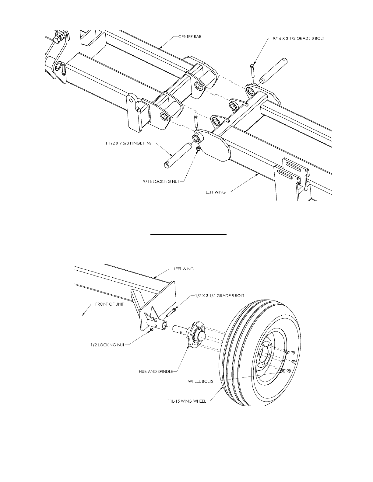
Figure 8
Attach the Wing Wheels
Attach the hub/spindle to the Axle Bracket using 1/2” x 3 1/2” grade 8 bolts and lock nuts. Mount
the wheels to the wing frames. Be sure the valve stem is pointing towards the outside. Refer to
Figure 9.
The remainder of the assembly steps can be done in either the transport or field position. Because
most people will assemble the unit in the field position (and it is recommended that you do), for
clarity, the following diagrams show the unit in the field position.
Figure 9
17
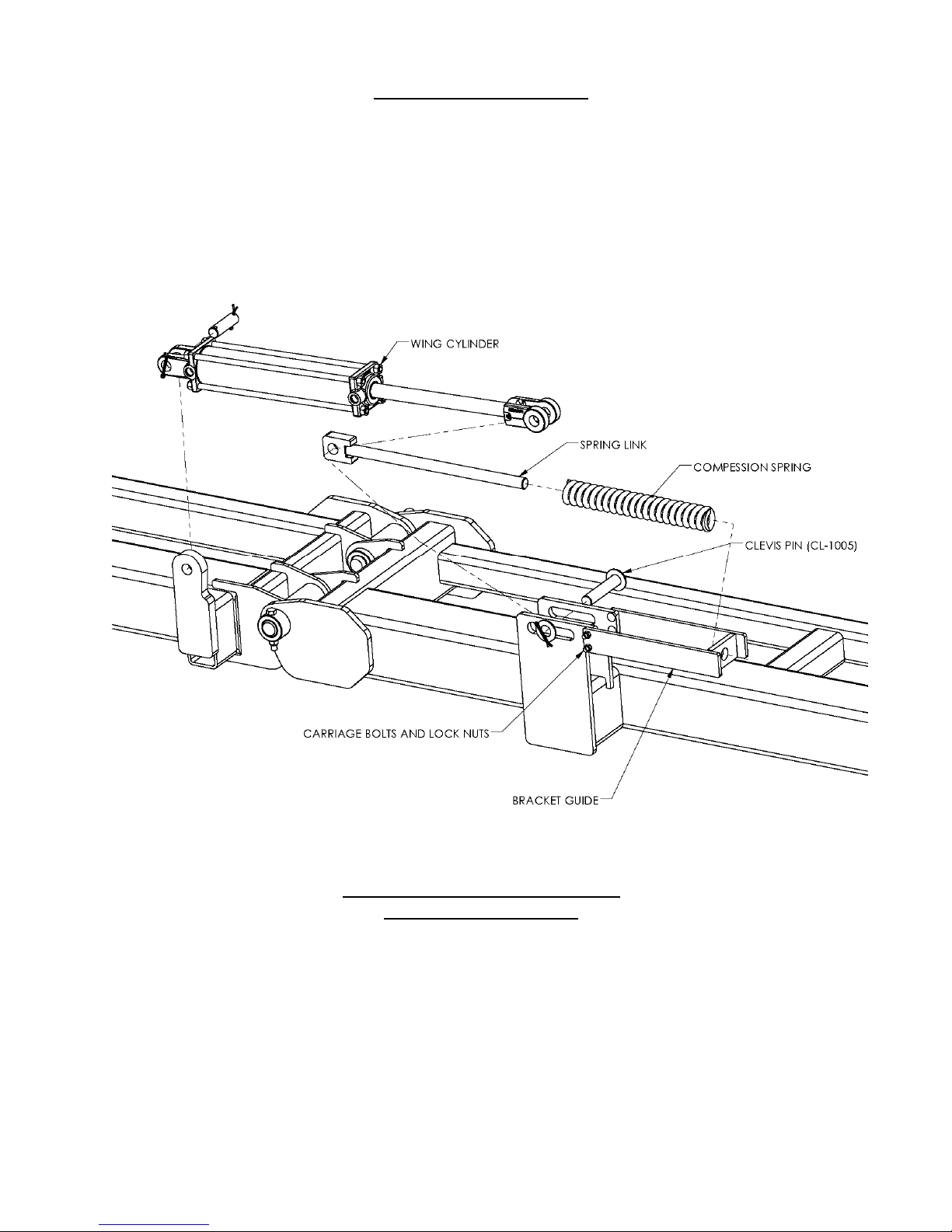
Attach the Wing Cylinders
1. Attach the Guide Brackets to the wing cylinder posts. Carriage bolts must face outward. Use
the 1 1/2” x 8 5/16” hinge pins, 1/2” x 3 1/2” grade 8 bolts, and locking hex nuts.
Refer to Figure 10.
2. Assemble the Spring Link (11959) through the compression spring (10682) and through the
hole in the bracket guide. Align the rod end clevis of the cylinder with the Spring Link and
the slot in the wing cylinder posts and secure with clevis pin (CL-1005).
3. Move entire assembly so that the cylinder base can be pinned to the cylinder post on the
Center Bar.
Refer to Figure 11 and the hydraulic system diagram in appendix B for more details.
1. Insert the tees (HYF-1809) with center O-ring fitting into the ports on the main frame
cylinders. Do not over tighten.
2. Attach the two similar male tees (HYF-1888) to the hydraulic tee bracket on the right side of
the Main Frame using the tee nuts.
3. Attach the two hoses from the right side tee to the front tee of the main lift cylinders. Be sure
to run the hoses through the loops welded to the frame.
Figure 10
Install the Main Frame Hydraulics
HDL-1124 through 1150
18
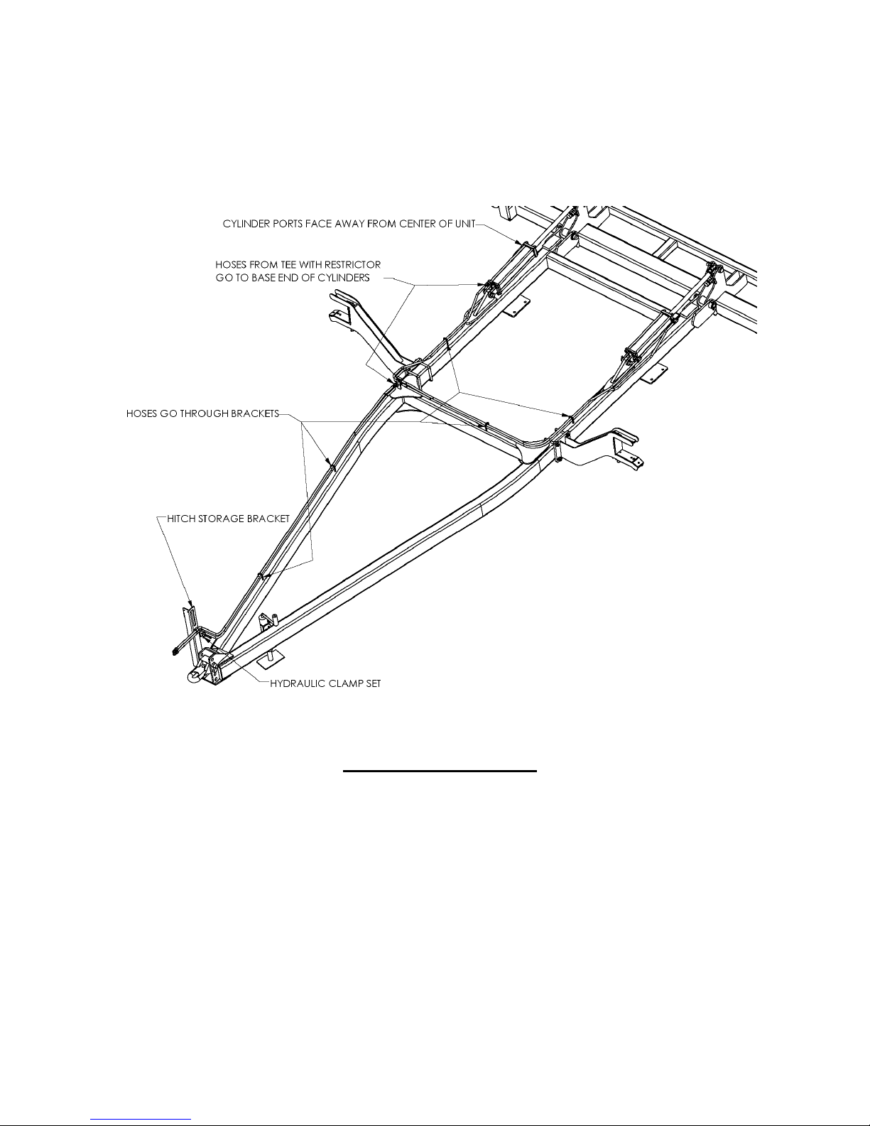
4. Attach the two hoses from the right side tee to the rear tee of the main lift cylinders. Be sure
to run the hoses through the loops welded to the frame.
5. Attach the two hoses from the right side tee to the hitch. Be sure to install the restrictor on the
tee with hoses going to the base end of the main cylinders. Secure these hoses to the Hitch
Storage Bracket with the Hydraulic Clamps. Refer to the parts diagram in appendix B for
details. Be sure to run the hoses through the loops welded to the frame.
Figure 11
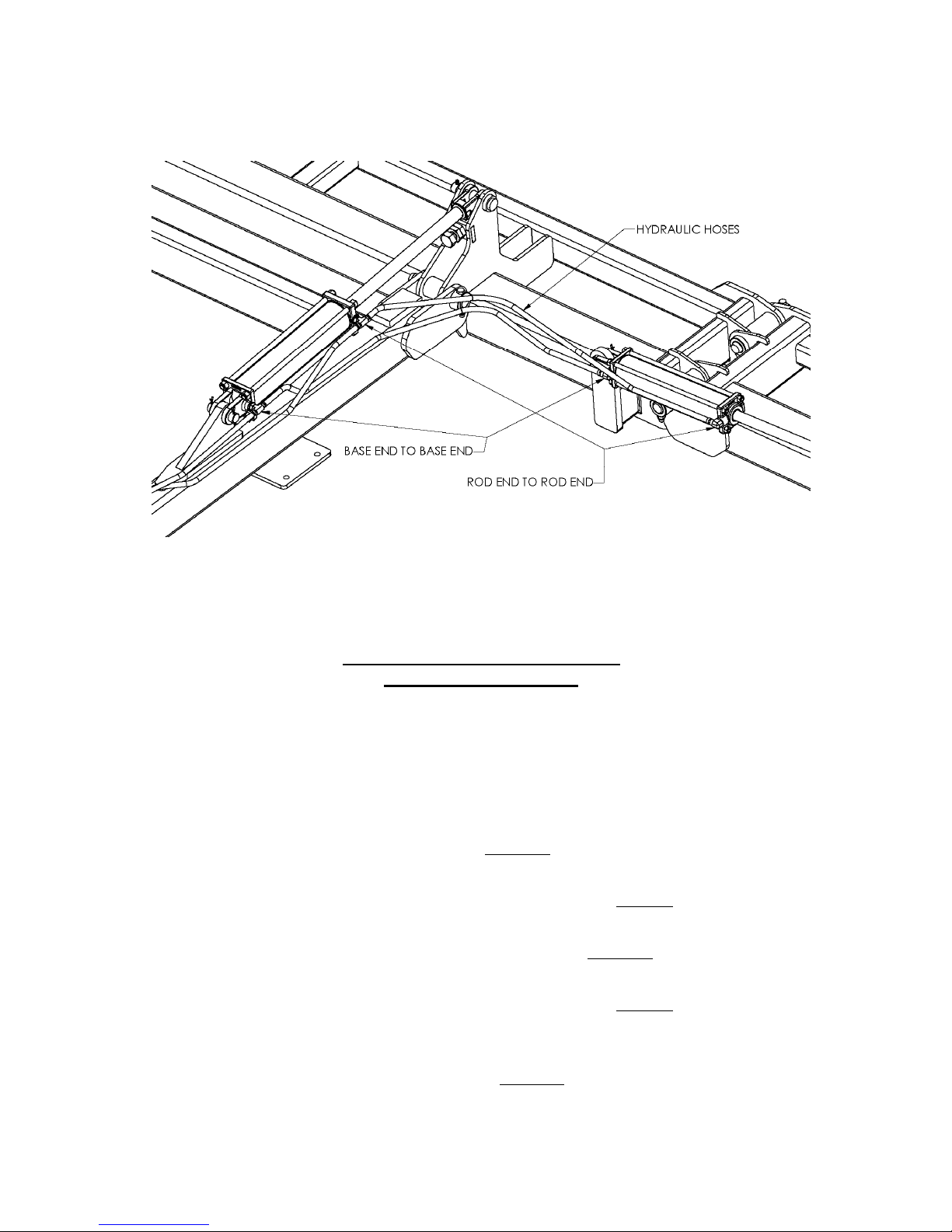
Install the Wing Hydraulics
Refer to Figure 12 and the hydraulic system diagram in appendix B for more details.
Complete the following assembly instructions for both left and right side of the unit.
1. Insert a 9/16”M – 3/4Morb, RST (HYF-2821) elbow into each of the ports on the 14” stroke
cylinders. Note the locations of the ports on the cylinders - ports face forward. Refer to the parts
diagram on page 42 for details. Do not over tighten.
2. Attach an (HYH-8057) hose between the base end tee of the main frame cylinders and the base end
elbow of the wing cylinder.
3. Attach an (HYH-8057) hose between the rod end tee of the main frame cylinders and the rod end
elbow of the wing cylinder.
19
Before further assembly, the hydraulic system must be filled with oil. Attach the unit to a tractor and
connect the hydraulic lines. Using hydraulic controls rotate the center bar and wings several times to
fill the cylinders and hoses with oil.
Figure 12
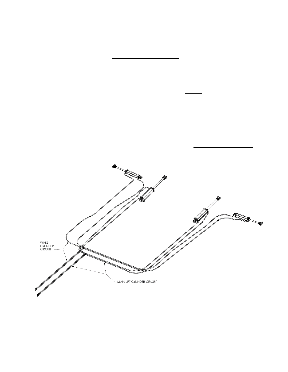
Install the Main Frame Hydraulics
HDL-1152 through 1160
Please note that the HDL-1152 through 1160 have two separate hydraulic circuits, one for the
Main Frame and one for the Wings.
Refer to Figure 13 and the hydraulic system diagram in appendix B for more details.
1. Attach the four male tee’s (HYF-1888) to the hydraulic tee brackets on the right side of the
Main Frame using the tee nuts. (two for main frame circuit two for wing circuit)
2. Attach two hoses from one of the tee’s to the base end of the main lift cylinders. Be sure to
run the hoses through the loops welded to the frame.
3. Attach two hoses from the other tee on the same bracket to the rod end of the main lift
cylinders. Be sure to run the hoses through the loops welded to the frame.
4. Attach two hoses from one of the other bracket tee’s to the base end of the wing cylinders. Be
sure to run the hoses through the loops welded to the frame.
5. Attach two hoses from the other tee on the same bracket to the rod end of the wing cylinders.
Be sure to run the hoses through the loops welded to the frame.
6. Attach the two hoses from the main lift cylinder circuit tee’s to the hitch. Be sure to install
the restrictor on the tee with hoses going to the base end of the cylinders.
20
7. Secure these hoses to the Hitch Storage Bracket with the Hydraulic Clamps. Refer to the parts
diagram in appendix B for details. Be sure to run the hoses through the loops welded to the
frame.
Install the Wing Hydraulics
Refer to Figure 13 and the hydraulic system diagram in appendix B for more details.
1. Attach two hoses from one of the other bracket tee’s to the base end of the wing cylinders. Be
sure to run the hoses through the loops welded to the frame.
2. Attach two hoses from the other tee on the same bracket to the rod end of the wing cylinders.
Be sure to run the hoses through the loops welded to the frame.
3. Attach the two hoses from the wing cylinder circuit tee’s to the hitch. Be sure to install the
restrictor on the tee with hoses going to the base end of the cylinders.
4. Secure these hoses to the Hitch Storage Bracket with the Hydraulic Clamps. Refer to the parts
diagram in appendix B for details. Be sure to run the hoses through the loops welded to the
frame.
Before further assembly, the hydraulic system must be filled with oil. Attach the unit to a tractor
and connect the hydraulic lines. Using hydraulic controls rotate the center bar and wings several
times to fill the cylinders and hoses with oil.
Figure 13
21
 Loading...