

Page 1
Q
McFarlane Aviation Wheel Balancer
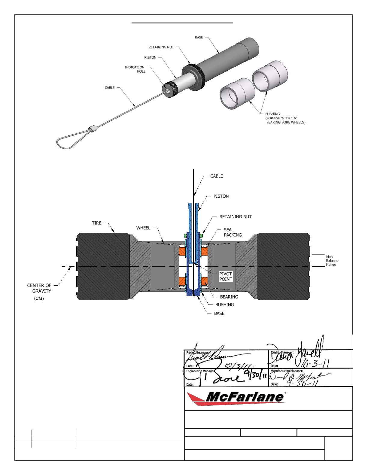
Figure 1 - Tool Components
Figure 2 - Wheel Assembly and Tool
Project Engineer:
Date: Date:
Engineering Manager: Manufacturing Manager:
Date: Date:
~ 08/18/2011 ORIGINAL
“X”: Bold letter indicates
revision level.
REVISION
Drawing:
WHEEL BALANCER INSTRUCTIONS
Size: A Scale: NA
DrawingNumber:
CONFIDENTIAL: Proprietary information of McFarlane Aviation, Inc. Reproduction, dissemination, and disclosure
is STRICTLY FORBIDDEN without the expressed written permission of McFarlane Aviation, Inc. All Rights
Reserved. Copyright McFarlane Aviation, Inc. (unpublished)
Drawn:
6652
uality Manager:
McFarlane Aviation, Inc.
696 East 1700 Road
Baldwin City, Kansas 66006
SD
Sheet:
of
1
2
~
Page 2
McFARLANE AVIATION SUSPENSION TYPE STATIC WHEEL BALANCER
INSTRUCTIONS
Note: This wheel balancer is to be used while the bearings are installed.
Failure to do this will result in improper balancing of the wheel.
1. Remove the Retaining Nut, ensure the surface of the balancer
Base and inner wheel bearing is clean and free of debris. See
below for the specific mounting instructions for 1 ¼” and 1 ½”
axles. If the wheel is equipped with a brake disc or drum,
balance the wheel with these in place. Wheel seals may be left in
place, or not.
1 ¼” Axle
Insert the Wheel Balancer Tool through the wheel bearings and
seals, and replace the Retaining Nut.
1 ½” Axle
Slide the Bushing over the Base. With the Bushing installed,
insert the Wheel Balancer Tool through the wheel bearings and
seals. Slide the second Bushing over the top of the Base and
slide it through the seals until the lip contacts the bearing. Once
this is in place, replace the Retaining Nut.
Note: The Retaining Nut keeps the balancer in the wheel while
handling. It does not tighten against anything.
2. Hang the cable from any fixed point (such as a bar clamped in a
vice) so that the wheel is suspended and free of any
obstructions.
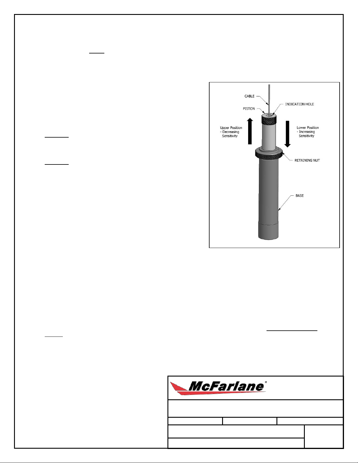
3. Raise the piston to the upper most position. Wait for the wheel
to come to rest and loosely add weights as needed to balance
wheel. Balance is achieved when Cable is centered in the
Indication Hole.
4. Lower the piston for greater sensitivity. Adjust weight to balance.
5. Repeat Step 4 until desired balance precision is achieved.
Note: The lower the Piston, the more sensitive the tool will become. If the Pivot Point is below the Center of Gravity,
balancing will become impossible and the Cable will stay touching the Indication Hole edge in whatever position you
place it. If this happens, move the piston upward, above the CG, and verify the balance.
6. Remove the wheel from the balancer and fix the weights to the wheel. For best dynamic balance results, weights
should be evenly divided between the top and bottom wheel surface. Reinstall the wheel on the balance r and check
the final balance, adjusting weights if required.
Note: The final piston height might not remain the
same for both sides of the wheel, since distance to
the CG may not be equal.
Drawing:
McFarlane Aviation, Inc.
696 East 1700 Road
Baldwin City, Kansas 66006
WHEEL BALANCER INSTRUCTIONS
Size: A Scale: NA
DrawingNumber:
6652
CONFIDENTIAL: Proprietary information of McFarlane Aviation, Inc. Reproduction, dissemination, and disclosure
is STRICTLY FORBIDDEN without the expressed written permission of McFarlane Aviation, Inc. All Rights
Reserved. Copyright McFarlane Aviation, Inc. (unpublished)
Drawn:
SD
Sheet:
of
2
2
~
 Loading...