

Page 1
www.mceinc.com
User Guide,
SmarTRAQ
Limitless Door Operator
11380 White Rock Road, Rancho Cordova, CA 95742 916 463 9200
Page 2

Motion Control Engineering, Inc.
11380 White Rock Road
Rancho Cordova, CA 95742
voice 916 463 9200
fax 916 463 9201
www.mceinc.com
User Guide,
SmarTRAQ Limitless Door Operator
Manual # 42-02-D001, Rev A.1, September 2003
Page 3

Copyright
Copyright 2003, Motion Control Engineering. All Rights Reserved.
This document may not be reproduced, electronically or mechanically, in whole or in part, without
written permission from Motion Control Engineering.
Trademarks
All trademarks or registered product names appearing in this document are the exclusive property
of the respective owners.
Warning and Disclaimer
Although every effort has been made to make this document as complete and accurate as possible,
Motion Control Engineering and the document authors, publishers, distributors, and
representatives have neither liability nor responsibility for any loss or damage arising from
information contained in this document or from informational errors or omissions. Information
contained in this document shall not be deemed to constitute a commitment to provide service,
equipment, or software by Motion Control Engineering or the document authors, publishers,
distributors, or representatives.
Limited Warranty
Motion Control Engineering (manufacturer) warrants its products for a period of 15 months from
the date of shipment from its factory to be free from defects in workmanship and materials. Any
defect appearing more than 15 months from the date of shipment from the factory shall be
deemed to be due to ordinary wear and tear. Manufacturer, however, assumes no risk or liability for
results of the use of the products purchased from it, including, but without limiting the generality
of the forgoing: (1) The use in combination with any electrical or electronic components, circuits,
systems, assemblies or any other material or equipment (2) Unsuitability of this product for use in
any circuit, assembly or environment. Purchasers’ rights under this warranty shall consist solely of
requiring the manufacturer to repair, or in manufacturer's sole discretion, replace free of charge,
F.O.B. factory, any defective items received at said factory within the said 15 months and
determined by manufacturer to be defective. The giving of or failure to give any advice or
recommendation by manufacturer shall not constitute any warranty by or impose any liability upon
the manufacturer. This warranty constitutes the sole and exclusive remedy of the purchaser and
the exclusive liability of the manufacturer, AND IN LIEU OF ANY AND ALL OTHER WARRANTIES,
EXPRESSED, IMPLIED, OR STATUTORY AS TO MERCHANTABILITY, FITNESS, FOR PURPOSE SOLD,
DESCRIPTION, QUALITY PRODUCTIVENESS OR ANY OTHER MATTER. In no event will the
manufacturer be liable for special or consequential damages or for delay in performance of this
warranty.
Products that are not manufactured by MCE (such as drives, CRT's, modems, printers, etc.) are not
covered under the above warranty terms. MCE, however, extends the same warranty terms that
the original manufacturer of such equipment provide with their product (refer to the warranty
terms for such products in their respective manual).
Page 4

Important Precautions and Useful Information
This preface contains information that will help you understand and safely maintain MCE
equipment. We strongly recommend you review this preface and read this manual before
installing, adjusting, or maintaining Motion Control Engineering equipment. This preface discusses:
• Safety and Other Symbol Meanings
• Environmental Considerations
•In This Guide
Safety and Other Symbol Meanings
Danger
This manual symbol is used to alert you to procedures, instructions, or situations which, if not done
properly, might result in personal injury or substantial equipment damage.
Caution
This manual symbol is used to alert you to procedures, instructions, or situations which, if not done
properly, might result in equipment damage.
Note
This manual symbol is used to alert you to instructions or other immediately helpful information.
Environmental Considerations
• Keep ambient temperature between 32 and 104 degrees F (0 to 40 degrees C).
• Prevent condensation on the equipment.
• Make certain that power line fluctuations are within plus or minus 10% of proper value.
In This Guide:
This guide is the installation, adjustment, and troubleshooting guide for SmarTRAQ. When
viewed online as a pdf file, hyperlinks link to related topics and informational websites. The
manual includes:
• Contents: Table of Contents. When viewed online as a pdf file, hyperlinks in the Contents
link to the associated topic in the body of the manual.
• SmarTRAQ: Product Description, installation, and troubleshooting instructions.
Page 5

SmarTRAQ Contents
About SmarTRAQ . . . . . . . . . . . . . . . . . . . . . . . . . . . . . . . . . . . . . . . . . . . . . . 1
Product Description . . . . . . . . . . . . . . . . . . . . . . . . . . . . . . . . . . . . . . . . . . . . 2
Adaptability . . . . . . . . . . . . . . . . . . . . . . . . . . . . . . . . . . . . . . . . . . . . . . . . . . . . . . . . . . . . . . . . . 3
SmarTRAQ Models . . . . . . . . . . . . . . . . . . . . . . . . . . . . . . . . . . . . . . . . . . . . . . . . . . . . . . . . . 4
Installation . . . . . . . . . . . . . . . . . . . . . . . . . . . . . . . . . . . . . . . . . . . . . . . . . . . 5
SmarTRAQ Adjustments . . . . . . . . . . . . . . . . . . . . . . . . . . . . . . . . . . . . . . . . 7
Checking Motor Rotation. . . . . . . . . . . . . . . . . . . . . . . . . . . . . . . . . . . . . . . . . . . . . . . . . . . . . . . 7
Learning Full Open and Full Close Positions . . . . . . . . . . . . . . . . . . . . . . . . . . . . . . . . . . . . . . 8
Running the Learn Operation . . . . . . . . . . . . . . . . . . . . . . . . . . . . . . . . . . . . . . . . . . . . . . . . 9
Verify Door Operation . . . . . . . . . . . . . . . . . . . . . . . . . . . . . . . . . . . . . . . . . . . . . . . . . . . . . . . . . 9
Adjusting Parameters . . . . . . . . . . . . . . . . . . . . . . . . . . . . . . . . . . . . . . . . . . . . . . . . . . . . . . . . 10
Troubleshooting . . . . . . . . . . . . . . . . . . . . . . . . . . . . . . . . . . . . . . . . . . . . . . 12
Helpful Hints . . . . . . . . . . . . . . . . . . . . . . . . . . . . . . . . . . . . . . . . . . . . . . . . . . . . . . . . . . . . . . . 12
Door Open and Door Close Logic . . . . . . . . . . . . . . . . . . . . . . . . . . . . . . . . . . . . . . . . . . . . 12
Door Close Limit and Door Open Limit . . . . . . . . . . . . . . . . . . . . . . . . . . . . . . . . . . . . . . . 12
Limit #1 and Limit #2 . . . . . . . . . . . . . . . . . . . . . . . . . . . . . . . . . . . . . . . . . . . . . . . . . . . . . 13
Car Door Bumpers . . . . . . . . . . . . . . . . . . . . . . . . . . . . . . . . . . . . . . . . . . . . . . . . . . . . . . . . 13
Belt and Chain Tension . . . . . . . . . . . . . . . . . . . . . . . . . . . . . . . . . . . . . . . . . . . . . . . . . . . . 13
Motor Terminal Designation . . . . . . . . . . . . . . . . . . . . . . . . . . . . . . . . . . . . . . . . . . . . . . . . 13
Learn Operation . . . . . . . . . . . . . . . . . . . . . . . . . . . . . . . . . . . . . . . . . . . . . . . . . . . . . . . . . . 14
Changing Parameters . . . . . . . . . . . . . . . . . . . . . . . . . . . . . . . . . . . . . . . . . . . . . . . . . . . . . . 14
Stall Protection . . . . . . . . . . . . . . . . . . . . . . . . . . . . . . . . . . . . . . . . . . . . . . . . . . . . . . . . . . . 14
Door Open and Door Close Protection Timers . . . . . . . . . . . . . . . . . . . . . . . . . . . . . . . . . 14
Temporary Operation for Evaluation . . . . . . . . . . . . . . . . . . . . . . . . . . . . . . . . . . . . . . . . . 14
Encoder Cable . . . . . . . . . . . . . . . . . . . . . . . . . . . . . . . . . . . . . . . . . . . . . . . . . . . . . . . . . . . . 14
Functional Troubleshooting . . . . . . . . . . . . . . . . . . . . . . . . . . . . . . . . . . . . . . . . . . . . . . . . . . . 15
Power Up . . . . . . . . . . . . . . . . . . . . . . . . . . . . . . . . . . . . . . . . . . . . . . . . . . . . . . . . . . . . . . . . 15
Motor Synchronization . . . . . . . . . . . . . . . . . . . . . . . . . . . . . . . . . . . . . . . . . . . . . . . . . . . . . 16
First Door Closing . . . . . . . . . . . . . . . . . . . . . . . . . . . . . . . . . . . . . . . . . . . . . . . . . . . . . . . . . 16
Learn Process . . . . . . . . . . . . . . . . . . . . . . . . . . . . . . . . . . . . . . . . . . . . . . . . . . . . . . . . . . . . 17
First Open/Close After Cycling Power . . . . . . . . . . . . . . . . . . . . . . . . . . . . . . . . . . . . . . . . 19
Opening and Closing . . . . . . . . . . . . . . . . . . . . . . . . . . . . . . . . . . . . . . . . . . . . . . . . . . . . . .20
Reopening and Reclosing (Fire Phase II Operation) . . . . . . . . . . . . . . . . . . . . . . . . . . . . 21
Torque Adjustment . . . . . . . . . . . . . . . . . . . . . . . . . . . . . . . . . . . . . . . . . . . . . . . . . . . . . . . .22
Page 6
SmarTRAQ
•About SmarTRAQ
• Product Description
• Installation
•Adjustment
• Troubleshooting
About SmarTRAQ
SmarTRAQ is a closed-loop technology door operator designed to replace older
mechanical circuits, cams, and resistors with a digital control system providing
precise door operation and reliable performance. SmarTRAQ dramatically improves door operation regardless of lobby door mass and wind loading. SmarTRAQ is A17.1, CSA-B44.1 compliant.
SmarTRAQ provides flexibility:
• Choose to modernize an existing installation economically with a new brushless motor and
microprocessor-based inverter drive (re-using existing mechanical equipment)
• Replace the complete operator with a new brushless motor, microprocessor-based inverter
drive, and new center-parting or side-slide operator package.
This user guide provides installation, adjustment, and troubleshooting information for the
SmarTRAQ motor and inverter drive. If your installation includes a new operator package,
additional instructions will be provided.
1
Page 7

SmarTRAQ
Product Description
The SmarTRAQ limitless, closed-loop, door operator includes a permanent-magnet, brushless
motor with a built-in encoder and a microprocessor-based inverter drive. The compact inverter
drive enclosure mounts easily on the elevator car. The motor replaces the original motor when
re-using existing operator packages or mounts to the new operator package when the complete
door operator is being replaced or newly installed.
Table 1.1 SmarTRAQ Specifications, Interface Data, and Code Compliance
Door Operator Drive Technical Data
Input Voltage 120VAC, 50/60Hz, Single-phase
Output Voltage 3-Phase, 30VAC, 9A (26A peak)
Power Requirement 300VA
Controller Type Closed Loop, Distance and Velocity Feedback, Limitless
Door Motor Technical Data
Type Three-phase, synchronous, brushless motor with perma-
nent magnet excitation and built-in digital encoder
Motor 0.564 HP, 3-Phase AC, 8-Pole, 30 Volt, 9A (26A peak),
0 — 2000 RPM, 0 — 133Hz
Encoder 640 PPR (Pulses Per Revolution)
Elevator Control Interface Data
Input Signals Door Open
Door Close
Nudging
Heavy Door
Input Signal Level Dry Contact
Output Signals Door Open Limit
Door Close Limit
Limit 1
Limit 2
Output Signal Level N.O./N.C. Contact, 10 Amp
Code Compliance
For ASME A17.1-1996 (Rule 210.15), ASME A17.1-2000/CSA B44-00 (Requirement 2.26.5), or CSA B44-94
(Requirement 3.12.1.5) compliance, mechanical Door Position Monitoring Switch must be provided.
2 Manual # 42-02-D001 Rev. A.1
Page 8

Adaptability
SmarTRAQ offers wide mechanical and electrical interface, providing a cost-effective solution
for modernization of existing door operators or for new installations. SmarTRAQ models support:
•MCE
• Center-Parting Operator Package
• Two-Speed Center-Parting Operator Package
• Single-Speed Side Slide Operator Package
• Two-Speed Side Slide Operator Package
•Westinghouse
• Model A Series
• Model B Series
• Model BB2
•Model E Series
•Model EZ
•Model HY
•Model MG
•Haughton
•T
•T1
•TH
•Montgomery
•MAC Series
•Dover
•DC Series
•HD Series
• Otis
•6970
•7300
• 7782
•GAL
• All Models
•Armor
•C4
Product Description
3
Page 9
SmarTRAQ
SmarTRAQ Models
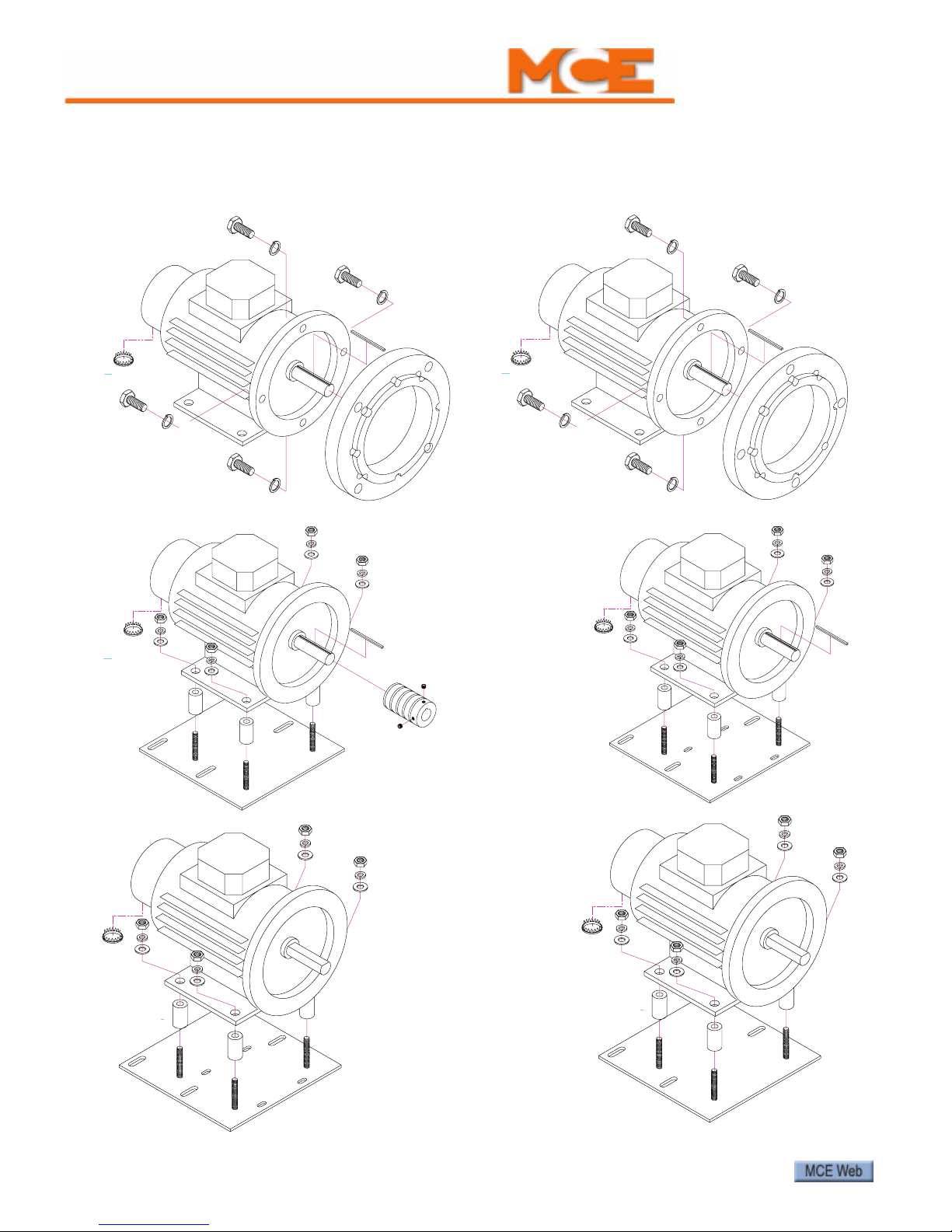
To support a wide selection of door operators, SmarTRAQ motor configurations include:
Figure 1.1 Motor Configurations
Model 4151-F
Otis 7300
Westinghouse A, B, and BB2
Model 4157-F
Otis 6970
Model 4152-B2
Haughton TH
Model 4150-B1
MAC
Westinghouse EZ
Model 4151-B1
Armor C4
GAL (all models)
Haughton T and T1
Otis 7782
Westinghouse E and HY
Model 4150-B3
Dover DC and HD
4 Manual # 42-02-D001 Rev. A.1
Page 10

Installation
1. Remove existing motor (replacement installations only). SmarTRAQ inverter drive may
be used only with SmarTRAQ motor.
2. If the car door gate switch is part of the existing limit switch box, leave it in place. Otherwise, limit switches are not required.
3. Install new motor.
Note
All door operators must have FULL OPEN and FULL CLOSE bumpers.
Caution
Otis 6970 Door Operators: When removing the Otis motor, access to the lower bolt is
through the inspection cover on the front of the gear case:
• Remove the inspection cover.
• Rotate the gear so one of the large holes exposes the lower bolt.
• Be careful not to drop the bolt or the lock washer in the gear case.
• Oil checks need to be adjusted for minimal effect. However, do not completely back out
existing oil check adjustments.
Installation
4. Unless the existing belt is in like-new condition, replace it with a robust, grip-type belt
with notches.
5. Adjust belt tension. (Closed-loop control requires minimal belt elasticity, slack, or slippage.)
6. Adjust all chains and cables for minimal slack.
7. Mount the inverter drive enclosure in a location that allows the provided 8-foot (2.5
meter) encoder cable to easily reach from the motor to the enclosure. (Coil any excess
cable length inside the drive enclosure. Avoid trimming the encoder cable.)
Note
If the encoder cable is trimmed, a brown (unused) wire will be exposed. Do not use the brown
wire. Note that the original yellow/green wire was actually a short piece soldered to the cable
shield. This piece must be replaced, soldered to the shield, and connected as shown in the wiring diagram provided.
8. Connect the encoder cable and power wires from the motor to the inverter drive as
shown in the wiring diagram. Please refer to “SmarTRAQ Wiring Diagram” on page 1-6.
9. Complete wiring connections between the inverter drive enclosure and the elevator controller as shown in the wiring diagram. Refer to the controller manufacturer job prints
for guidance.
5
Page 11

9
10
7
8
DOOR OPEN
DOOR CLOSE
L2D
L1D
GND
INPUT
CLOSED LOOP DOOR
SMARTRAQ LIMITLESS
120VAC 1
POWER
INPUTS
TB-5
1
2
3
4
TB-2
1
TB-3
5
6
9
7
8
+S
-S
-E
ENC1
ENC0
SOUT
MOTOR
V
U
W
N
DOOR
14 AWG
OPERATOR
ENTER
NUDGING
3
NUDGE
REMOTE
LOCAL
OPEN
CLOSE
ONBOARD PROGRAMMER
12
11
DOL
6
5
LIMIT 2
TB-4
YELLOW/GREEN
RED
BLUE
BLACK
WHITE
GREEN
FH
3
2
/
10
A MDQ OR
EQUIVALENT
120 V.A.C., 1 , 50/60HZ
H
10
4
DOOR OPEN
LIMIT OUTPUT
TO CONTROLLER
TO CONTROLLER
LIMIT 2 OUTPUT
(RATED AT MAXIMUM
120VAC/24VDC, 10AMP)
HEAVY DOOR
(RATED AT MAXIMUM
120VAC/24VDC, 10AMP)
9
7
8
120VAC/24VDC, 10AMP)
(RATED AT MAXIMUM
LIMIT 1 OUTPUT
TO CONTROLLER
3
2
1
LIMIT 1
OPEN
HEAVY DOOR
10
9
NUDGING
3
8
7
TB-5
INPUTS
OPTIONAL
NOTE: IF COMPLIANCE TO ASME A17.1-1996 (RULE 210.15),
ASME A17.1-2000/CSA B44-00 (REQUIREMENT 2.26.5),
OR CSA B44-94 (REQUIREMENT 3.12.1.5) IS REQUIRED,
A MECHANICAL DOOR POSITION MONITORING SWITCH MUST
BE PROVIDED.
DOOR
INSPECTION
(LP)
(LC)
TO CONTROLLER
(RATED AT MAXIMUM
120VAC/24VDC, 10AMP)
LIMIT OUTPUT
DOOR CLOSE
DCL
SmarTRAQ
Figure 1.2 SmarTRAQ Wiring Diagram
120 V.A.C., 1 , 50/60HZ
GGNNH
FH
2
3
/
A MDQ OR
10
EQUIVALENT
NOTE: IF COMPLIANCE TO ASME A17.1-1996 (RULE 210.15),
LIMIT 1 OUTPUT
TO CONTROLLER
120VAC/24VDC, 10AMP)
TO CONTROLLER
120VAC/24VDC, 10AMP)
LIMIT 2 OUTPUT
TO CONTROLLER
120VAC/24VDC, 10AMP)
(RATED AT MAXIMUM
DOOR CLOSE
LIMIT OUTPUT
(RATED AT MAXIMUM
(RATED AT MAXIMUM
TB-4
DOOR OPEN
LIMIT OUTPUT
TO CONTROLLER
(RATED AT MAXIMUM
120VAC/24VDC, 10AMP)
HEAVY DOOR
NUDGING
DOOR
OPEN
OPTIONAL
INSPECTION
TB-5
3
7
8
HEAVY DOOR
NUDGING
DOOR CLOSE
DOOR OPEN
INPUTS
TB-5
9
ASME A17.1-2000/CSA B44-00 (REQUIREMENT 2.26.5),
OR CSA B44-94 (REQUIREMENT 3.12.1.5) IS REQUIRED,
A MECHANICAL DOOR POSITION MONITORING SWITCH MUST
BE PROVIDED.
10
SMARTRAQ LIMITLESS
CLOSED LOOP DOOR
OPERATOR
L2D
120VAC 1
INPUT
POWER
L1D
GND
1
LIMIT 1
2
(LP)
3
4
5
DCL
6
7
8
LIMIT 2
(LC)
9
10
11
DOL
12
3
7
8
INPUTS
9
10
ONBOARD PROGRAMMER
NUDGE
LOCAL
REMOTE
OPEN
CLOSE
--++ENTER
TB-3
TB-2
SOUT
9
ENC0
8
ENC1
7
-E
6
-S
5
+S
1
N
4
W
3
V
2
U
1
GREEN
WHITE
BLUE
BLACK
YELLOW/GREEN
RED
MOTOR
DOOR
14 AWG
6 Manual # 42-02-D001 Rev. A.1
Page 12

SmarTRAQ Adjustments
Adjustment consists of:
• Checking motor rotation
• Learning Full Open and Full Close positions
• Verifying Operation
• Adjusting parameters
Checking Motor Rotation
Motor control connections from inverter drive enclosure terminals TB2 and TB3 to the motor
assume clockwise motor rotation when elevator doors are closing. It is important to verify that
this is the case:
1. Manually open and close elevator doors while watching motor rotation.
2. Viewed from the motor shaft end, motor must rotate clockwise when doors are closing.
If so, connections shown in the wiring diagram and in the table below are correct:
Table 1.2 Motor Connections from Wiring Diagram
Motor TB2 Connector
U1 Terminal 1
V1 Terminal 2
W1 Terminal 3
NTerminal 4
TB3 Connector
SOUT Terminal 9
ENC0 (white) Terminal 8
ENC1 (blue) Terminal 7
-E Terminal 6
-S Terminal 5
+S Terminal 1
SmarTRAQ Adjustments
3. If, as viewed from the shaft end, motor rotates counter-clockwise when doors are closing, connections must be changed as shown in the following table:
Table 1.3 Motor Connections if Rotation is Counter-Clockwise as Doors Close
Motor TB2 Connector
U1 Terminal 1
V1 Terminal 3 (changed)
W1 Terminal 2 (changed)
NTerminal 4
SOUT Terminal 9
ENC0 (white) Terminal 7 (changed)
ENC1 (blue) Terminal 8 (changed)
-E Terminal 6
-S Terminal 5
+S Terminal 1
TB3 Connector
7
Page 13

SmarTRAQ
Learning Full Open and Full Close Positions
Door Open and Door Close Limits are learned during an automated learn process as current
rises when doors reach full open or full close. Once limits are learned, SmarTRAQ is able to dis-
tinguish between an obstruction and full open or full close positions. DOL (Door Open Limit)
and DCL (Door Close Limit) are learned only within the last 3/8” of door travel in either direction.
• Doors Full Open: Door Open Limit is OPEN
• Doors Full Closed: Door Close Limit is OPEN
Note
Parameter values can only be changed or viewed when elevator doors are Full Closed and Door
Close Limit is OPEN.
You run the learn operation for Door Open and Door Close Limits through programmer
switches in the inverter drive enclosure. These switches are:
• Local/Remote: Two-position toggle switch, selecting:
• Local: Local inverter drive control (from programmer switches)
• Remote: Remote inverter drive control (from elevator controller)
• Open/Close: Three-position, spring-loaded switch active when Local control is selected:
• Open: Opens elevator doors
• Close: Closes elevator doors
• Nudge: Push button. Closes doors at nudging speed when Close is activated.
• - and +: Push buttons. Used to select a parameter to be adjusted and to change value of a
parameter after it is selected.
• Enter: Displays a selected parameter and saves its value after editing.
Figure 1.3 Inverter Drive Programmer Switches
OPEN LOCAL
CLOSE NUDGE REMOTE
8 Manual # 42-02-D001 Rev. A.1
_
+ENTER
Page 14

Running the Learn Operation
1. Verify that elevator doors are closed.
2. Place Local/Remote switch in the Local position.
3. Turn on power.
For a few seconds, dashes will be displayed on the LED display. Then, the dash on the right
hand display will disappear. The inverter drive is ready to accept input.
4. Hold the Open/Close switch in the Close position until PL is displayed. (Motor will cog
to synchronize rotor.)
5. Press Enter to select the PL parameter.
6. Press Enter a second time.
7. Press - (minus) to display Lr (Learn).
8. Press Enter.
Dashes will be displayed for a moment, then PL will appear. Doors will automatically open at
low speed to FULL OPEN position and will then automatically close at low speed to their FULL
CLOSE position. Learning is complete.
Verify Door Operation
SmarTRAQ Adjustments
Note
Whenever power is turned on, the first open operation will be at Low Speed.
To verify door operation:
1. Hold Open/Close in Open position. Doors will open and detect Full Open position. DOL
should be OPEN.
2. Hold Open/Close in Close position. Doors will close and detect Full Close position. DCL
should be OPEN.
9
Page 15

SmarTRAQ
Adjusting Parameters
All door operator adjustments are made by selecting and changing parameters using inverter
drive programmer switches. All parameter values are numeric, from 0 to 31. The higher the
number, the greater the parameter value.
Note
Parameter values can only be changed or viewed when elevator doors are Full Closed and Door
Close Limit is OPEN.
After changing parameters, you must select the parameter “do” and press Enter to put door
operator back in operating mode. You must also place the Local/Remote switch back in Remote
position. (Otherwise, operator will not respond to open or close commands from elevator controller.)
Use the following table and the Motion Profile illustration to adjust parameters.
Table 1.4 Inverter Drive Parameters
Parameter Description
PL Start Open Position: Position where doors start to accelerate. Higher value = Position
farther from full close.
P2 Open Slowdown Position: Position where doors begin to reduce high opening speed
and decelerate to low opening speed. Higher value = High speed reduces nearer to
full open position.
P7 Close Slowdown Position: Position where doors begin to reduce high closing speed
and decelerate to low closing speed. Higher value = High speed reduces nearer to
full close position.
Po Reopen Slowdown Position: Higher value = Reopen slowdown position starts nearer
to full open.
Pc Reclose Slowdown Position: Higher value = Reclose slowdown position starts nearer
full close.
Pr Reopen Distance: Distance from full open where Po parameter, Reopen Slowdown
Position, and Ar parameter, Reopen Deceleration, can be activated. 00 value = from
full open to 75% of full open. Setting parameter from 01 to 31 = from 75% of full
open to 25% of full open. Note: Most door operators will not require adjustment of
this parameter. This parameter is factory set to 00. Should be set to 00 unless abso-
lutely necessary. See Caution following this table.
U0 Start Open Speed: Higher value = More speed.
U1 High Opening Speed: Higher value = More speed.
U2 Low Opening Speed: Higher value = More speed.
U3 High Closing Speed: Higher value = More speed.
U4 Low Closing Speed: Higher value = More speed.
Ud Nudging Speed: Higher value = More speed.
A0 Opening Acceleration: Higher value = Faster acceleration.
A1 Opening Deceleration: Higher value = Faster deceleration.
A2 Closing Acceleration: Higher value = Faster acceleration.
A3 Closing Deceleration: Higher value = Faster deceleration.
Ab Braking Deceleration: Deceleration during door reversal. Higher value = More decel-
eration.
Ar Reopen Deceleration: Higher value = Faster deceleration.
10 Manual # 42-02-D001 Rev. A.1
Page 16

Table 1.4 Inverter Drive Parameters
Parameter Description
F3 Heavy Door High Closing Speed: Higher value = More speed. This value must be
lower than U3.
F7 Heavy Door Close Slowdown Position: Position where doors begin to reduce high
closing speed and decelerate to low closing speed. Higher value = High speed
reduces nearer to full close position.
C1 Full Open Torque: Higher value = Higher Full Open Torque.
C3 Close Torque: Higher value = More torque.
Co Hold Open Torque: Higher value = More torque. Torque when doors are full open.
Cc Hold Close Torque: Higher value = More torque. Torque when doors are full close.
This value must be lower than the C3 value.
Cb Braking torque: Limits braking torque during slowdown. Higher Value = More braking
torque. Lower Value = Less braking torque. 00 value has no effect. Should be set to
00 unless absolutely necessary. See Caution following this table.
LP Limit 1: Higher value = Output turns on when doors are nearer to close position.
Lower value = Output turns on when doors are farther from full close position.
LC Limit 2: Higher value = Output turns on when doors are nearer to open position.
Lower value = Output turns on when doors are farther from full open position.
do Select Operation Mode: Once a parameter is adjusted, operation mode must be
selected. Otherwise, door operator will not respond to open or close commands.
Lr Learn Command:
SmarTRAQ Adjustments
Caution
Pr and Cb parameters should always be set to “00” unless absolutely necessary. Please refer
to “Opening and Closing” on page 1-20 for Cb. Please refer to “Reopening and Reclosing
(Fire Phase II Operation) ” on page 1-21 for Pr.
Figure 1.4 Motion Profile
LC
LP
11
Page 17

SmarTRAQ
Troubleshooting
This section is divided into two topics:
• Helpful Hints: Real world information about door operator functions that can help with
adjustment, repair, or troubleshooting.
• Functional Troubleshooting: Specific information to help the installer overcome most
common problems encountered during SmarTRAQ installation.
Helpful Hints
Helpful Hints describes:
• Door Open and Door Close Logic
• Door Close Limit and Door Open Limit
• Limit #1 and Limit #2
• Car Door Bumpers
• Belt and Chain Tension
• Motor Terminal Designation
• Learn Operation
• Changing Parameters
• Stall Protection
• Door Open and Door Close Protection Timers
• Temporary Operation for Evaluation
•Encoder Cable
Door Open and Door Close Logic
SmarTRAQ is designed to allow power to be applied indefinitely to hold doors open or closed.
With some controller designs, Otis comes to mind, a single relay or single family of relays is
energized to open doors and then that same relay or relays are de-energized to close doors. Hold
open torque parameter “Co” is used to hold doors open and hold close torque parameter “Cc” is
used to hold doors closed. This feature is especially useful if doors tend to drift partially closed,
when open power is removed, when fully open or drift partially open when fully closed, when
close power is removed. Care must be exercised when designing door open and door close logic
circuits. Be sure to check that door operation is proper during all types of operations, including,
but not limited to, Automatic, Independent, Attendant, Hospital Service, Fire Phase I, Fire
Phase II, and Inspection. If doors drift closed when controller power is removed, then some sort
of door hold open device may be required.
Door Close Limit and Door Open Limit
DCL and DOL are generated electronically when doors reach full close position or full open
position, up against the bumpers, and current increases. After an unobstructed “learn operation”, SmarTRAQ knows the difference between an obstruction and full open or full close position. DCL and DOL can only be generated within approximately the last one half inch of travel.
DOL and DCL have loss of power memory. When power is restored after a power loss, DCL will
be re-established if doors were fully closed or DOL will be re-established if doors were fully
open prior to power interruption.
12 Manual # 42-02-D001 Rev. A.1
Page 18

Troubleshooting
Limit #1 and Limit #2
With some controllers, generating DCL when current increases after doors are fully closed may
be too late to satisfy controller logic. In those cases, wire Limit #1 in series with DCL. Limit #1 is
then programmed with parameter “LP” to open at a position before doors are fully closed.
Note
The door close signal must remain on until DCL is generated electronically for doors to be considered fully closed. After loss of power, until doors have opened and closed, Limit #1 will not be
established. This is the reason Limit #1 is wired is series with DCL. In this manner, DCL will
activate when current increases at the mechanical limit of travel during the “learn operation,”
power up, and first open and close cycle, Limit#1 will activate for any subsequent operations.
Limit #1 can also be used to bypass the retiring cam contact with controllers that use a retiring
cam contact paralleled with a door position contact in door open logic.
Limit #2 works in a similar manner and uses parameter “LC” to determine the position where it
activates. Limit #2 can be programmed to activate near full open position.
Caution
Limit #1 and Limit #2 must not be used to remove the door open and door close signal to
the SmarTRAQ drive. Doors must reach full open position and generate DOL electronically
before removing door open signal to drive. Doors must reach full closed position and generate DCL electronically before removing door close signal to drive.
Car Door Bumpers
All door operators must have both open and close bumpers. For proper operation, it is very
important that car door bumpers are in good shape and securely mounted. Doors must stop on
the open door bumper at full open position and on the close door bumper in full closed position.
It is also very important that car doors stop on car door bumpers at every floor. Make sure
hoistway door bumpers, if provided, do not stop car doors before car door bumpers.
Belt and Chain Tension
Belts and chains must be tensioned properly, much tighter than normally expected. Belts must
be in good shape. If after tension adjustment, belts still slip, they must be replaced. Secondary
drive V-belts on MAC and Dover Door Operators tend to slip, this is why GAL and ECI use a
chain as part of their design. The belt type should be changed from a simple, inexpensive V-belt
to a more robust grip type V-belt with notches and additional traction provided on the sides of
the belt. With closed-loop control, power transmission from the motor/encoder to doors must
have absolute minimum elasticity, slack, and slippage.
Motor Terminal Designation
The motor has six terminals, but only four are used. Looking down at the motor from above
with the shaft facing you: Starting on the left side closest to the shaft, the first terminal is “W”,
then “V” in the middle, and “U” toward the encoder end. The middle terminal on the right side
is “N.”
13
Page 19

SmarTRAQ
Learn Operation
The “learn operation” can only take place if the drive thinks the doors are fully closed, this is
indicated by displaying “PL” and
“PL” is displayed. Reduce “C1” parameter if torque is too high in open direction. Reduce “C3”:
parameter if torque is too high in close direction.
an active DCL. Hold Open/Close switch in close direction until
Changing Parameters
Parameters can only be changed if the drive thinks the doors are closed. If pressing the “Enter”
button changes parameter value then the doors are closed. If pressing the “Enter” button does
not change the parameter, then holding the Open/Close switch until the doors are fully closed
and, at the same time, pressing the “Enter” button allows you to change the parameter.
Stall Protection
SmarTRAQ has built-in stall protection in both directions of travel. In the open direction, an
internal stall timer is set for one minute. If the door open signal to the drive is activated for
more than one minute, the drive will automatically shut off. The drive will not respond until the
signal is removed and reapplied or the opposite direction signal is applied. The stall timer for
the close direction operates in a similar manner, but is set for two minutes.
Door Open and Door Close Protection Timers
Door open and door close protection timers must be set longer than it takes the doors to open or
close at the lowest speeds, first open operation after restoring power and nudging close.
Temporary Operation for Evaluation
Temporary operation for evaluation can be accomplished easily by removing the existing motor
and setting it aside without removing the wires. Rest the drive on the car top. Install the new
motor and wire the motor and encoder to the drive. Wire the drive to a power cord with a plug.
Plug the power cord into the car top electrical outlet. Turn on power and adjust the door operator. Once you’re satisfied that everything is OK, either return the door operator to its original
condition or remove the old motor and temporary wiring, mount the drive, wire the new motor
and encoder to the drive and wire the drive to the controller.
Encoder Cable
The encoder cable is approximately eight (8) feet long with six (6) pre-striped wires and a small
piece of shrink tubing on one end. The wires are; black, white, red, green, blue and yellow/
green. The other end of the cable is connected internally to the motor. We recommend that the
cable be kept at its original length and the excess, if any, coiled up in the drive enclosure. However, if the cable length is reduced you’ll notice that there is no yellow/green wire, but there is a
brown wire. The brown wire is not used and the yellow/green wire is actually a short piece of
wire attached to the shield.
14 Manual # 42-02-D001 Rev. A.1
Page 20

Functional Troubleshooting
Steps in this section are provided in “installation order” to specifically help the installer through
the process.
Power Up
When power is applied to the SmarTRAQ Drive, the GREEN LED on the main board is ON. The
RED LED on the main board should remain OFF.
The Programmer board will display a SINGLE BAR and REMOTE or LOCAL led is ON.
IF… Programmer display and Remote or Local LEDs are off and green LED on main board
is on:
1. Check connections between main board and programmer board.
2. Verify connectors are inserted correctly.
IF… Programmer display and Remote or Local LEDs are off and green LED on main board
is off:
1. Confirm correct AC voltage provided to terminals.
2. Check all connections between AC voltage supply from controller to transformer in the
drive.
3. Confirm main line disconnect switch is ON.
4. Confirm all fast connectors inside drive are inserted correctly.
5. Confirm that no pieces of conductive material dropped onto boards.
6. Check fuses in drive.
Troubleshooting
IF… The red LED on main board is on:
1. Confirm input voltage is correct.
2. Confirm that no pieces of conductive material dropped onto boards.
3. Confirm all fast connectors inside drive are inserted correctly.
15
Page 21

SmarTRAQ
Motor Synchronization
If power up is successful, the door operator is ready to synchronize the motor.
1. Select LOCAL on the programming board.
2. Press Open/Close switch to provide a momentary OPEN or CLOSE command.
The motor will cog to synchronize the rotor. Time required for this operation varies, but should
be less than 10 seconds. When synchronization is complete, the door operator is ready to accept
commands.
IF… Motor does not cog and synchronize:
1. Confirm motor wires are connected correctly to main board at connector TB-2.
2. Confirm encoder wires are connected correctly to main board at connector TB-3.
3. Confirm programming board is connected correctly to main board and TB-8/J2 connectors are inserted correctly.
IF… Motor cogs indefinitely, drive shuts down (after two minutes), and red LED is ON:
1. Confirm ENCODER WIRES are connected correctly to main board at connector TB-3,
especially green wire on terminal 9.
2. Open rear cover of motor and check all connectors to make sure they are inserted correctly.
First Door Closing
If motor synchronization was successful, the next step is to CLOSE the doors. This is because
programming board parameters can only be accessed after the drive detects FULL DOOR
CLOSE and the DCL signal is ACTIVE. Even though doors were closed by hand, IT IS ALWAYS
NECESSARY to give a close command until DCL is activated. When the first full door close
position is detected and DCL is generated, “PL” will be displayed on the programmer board.
Parameters can now be accessed.
IF… Motor does not rotate properly, makes noise, or vibrates:
1. Confirm encoder wires are connected correctly to main board at connector TB-3.
2. Open rear cover of motor and check that all connectors are inserted correctly.
3. Confirm that the shielded wire of the encoder cable does not touch any metal part of the
enclosure or door operator.
4. If previous steps are OK, cycle power and repeat procedure.
IF… On the close command, doors move in open direction, brake, and drive resets:
1. Problems in start-up procedure were encountered and the drive reset. Procedure must
be repeated starting with Motor Synchronization.
2. If problems persist, cycle power and repeat entire procedure.
16 Manual # 42-02-D001 Rev. A.1
Page 22

Troubleshooting
IF… Doors reach close position but the DCL signal is not generated, there is probably slip-
page somewhere in the mechanical transmission system and the motor is still turning while the
doors are stopped:
1. Check belt tension. Tighten as necessary to prevent slippage. Grip-notch type belts may
be required.
2. Should step b) not be effective, stop motor by hand (minimal amount of pressure is usually required) so that DCL is generated. Change value of parameters from programming
board. Set a lower value for” C3” and “Cc”. In this manner, next time slippage occurs
while detecting full close torque should be reduced.
IF… DCL is generated but PL is not displayed:
1. Check connections between main board and programmer board.
Learn Process
If the first closing of the doors was completed correctly and DCL is active, the learning process
can be executed:
1. With “PL” displayed, press ENTER button once; a number will be displayed.
2. Press ENTER again. “PL” will be displayed.
3. Press minus (-) button to display “Lr”, then press ENTER button to start the learn process.
Doors should reach full open position, then reverse and reach full close position. During this
process, it is important that doors open to their maximum width and close completely (including additional turns the motor may make when doors are fully closed).
Completing the learn process is required for proper operation.
IF… You press ENTER and no numbers are displayed:
1. More than likely, DCL was not generated. Give close command again until DCL is generated.
IF… During opening, doors stop and reverse before reaching full open, the “C1” parameter
may be set too low or there is too much friction:
1. Ensure that doors move freely.
2. If possible, access programmer board and change value of parameter “C1” (DCL must be
generated) and repeat learning process.
3. If it is not possible to access the programmer board and change parameter “C1” because
DCL was not generated, cycle power and repeat procedure beginning with learn process.
4. Change the value of “C1” and repeat learning process again.
17
Page 23

SmarTRAQ
IF… During opening, doors reach full open and push up against bumper but do not
reverse, there is probably slippage somewhere in the mechanical transmission system and the
motor is still turning while doors are stopped:
1. If possible, stop motor by hand. Doors should now reverse and close. If not, turn off
2. Check the mechanical transmission system, tighten belts.
3. Repeat start up procedure. If problem persists, cycle power and repeat procedure begin-
4. Repeat until correct values for “C1” and “Co” are found.
IF… During opening, doors reach full open, push up against bumper, and stop with red
LED on, a fault condition occurred (most likely due to low AC input voltage):
1. Check AC voltage using a voltmeter. Check voltage continuously during opening, espe-
If voltage drop is excessive, and drive locks up, cycling power is required.
power and attempt to open doors again.
ning with first closing of the doors. After this, reduce value of “C1” and “Co” and execute
learning process.
cially when doors push up against full open bumper. Voltage should not drop below
120VAC – 10%.
2. Excessive voltage drop may be due to a poor connection between source and drive.
Wires may be undersized. Transformer in controller may be underrated.
3. As an experiment, temporarily use an alternate power source such as car lighting supply
or a building convenience outlet circuit and repeat learn process. If problem is resolved
in this manner, then a more robust power source from controller is required.
IF… During closing, doors reach full close, push up against bumper, and stop with red LED
ON, follow steps for the problem above.
IF… During closing, doors stop before reaching full close and DCL is generated, “C3” value
may be too small or there is too much friction:
1. Ensure doors move freely without excessive friction.
2. If doors move freely, increase “C3” and repeat learn process.
IF… During closing, doors reach full close and push up against bumper but DCL is not generated, there is probably slippage somewhere in the mechanical transmission system and the
motor is still turning while doors are stopped:
1. If possible, try to stop motor by hand (only a small amount of pressure is usually
required). The drive should now generate DCL. If not, turn off power.
2. Check mechanical linkage and transmission system. Tighten belts.
3. Repeat start up procedure. If problem persists, cycle power and repeat procedure
through first closing of doors. After this, reduce value of “C3” and execute learn process.
4. Repeat this step until correct value for “C3” is found.
18 Manual # 42-02-D001 Rev. A.1
Page 24

Troubleshooting
First Open/Close After Cycling Power
After power is cycled, and doors are in full close position with DCL active, an OPEN command
should be given using local command on programmer board. Doors will move in open direction
at REDUCED SPEED. If a CLOSE command is given before DOL is generated, doors will move
in close direction at REDUCED SPEED.
DOORS WILL MOVE AT REDUCED SPEED UNTIL FIRST DOL IS GENERATED.
This is necessary after having cycled power because the drive needs to determine a fixed reference point for door position. While the drive was turned off, the doors could have been moved.
BE SURE CONTROLLER DOOR OPEN PROTECTION TIMER HAS SUFFICIENT TIME TO
ALLOW FOR FIRST SLOW OPENING WITHOUT TRIPPING.
IF… After reaching full open, DOL is generated but doors close at reduced speed:
1. Check value of “U3” parameter. Increase if set too low.
2. Check that NUDGE speed was not inadvertently selected.
3. Check that HEAVY DOOR was not selected by controller.
4. Be sure learn process was performed correctly.
IF… After reaching full open, DOL is NOT generated and doors close at reduced speed,
there is probably slippage somewhere in the mechanical transmission system and the motor is
still turning when doors are stopped:
1. Tighten belts. Replace if worn. May need grip-notch type belts.
2. If problem persists, decrease “C1” and “Co” parameters.
IF… DOL is generated before doors reach full open and doors stop:
1. Check for excessive friction or an obstacle in path of doors.
2. If first step checks OK, increase “C1” parameter.
IF… After reaching full open, DOL is generated and doors close at correct speed but, when
fully closed, DCL is not generated, there is probably slippage somewhere in the mechanical
transmission system and the motor is still turning when doors are stopped:
1. Tighten belts. Replace if worn. May need grip-notch type belts.
2. Should problem persist, decrease “C3” parameter.
3. Should problem persist, repeat learn process.
IF… Red LED turns ON: Please refer to “During opening, doors stop and reverse before
reaching full open, the “C1” parameter may be set too low or there is too much friction: ” on
page 1-17.
IF… Doors move in close direction but stop before reaching full close and DCL is not generated:
1. Check that there is no obstruction.
2. Check that torque is sufficient to overcome friction.
3. If everything appears to be OK, increase “C3”.
19
Page 25

SmarTRAQ
Opening and Closing
Open and closing operations are accomplished by setting parameters for:
• High Speed Open and Close speeds using “U1/ U3”.
• Low Speed Open and Closing speeds using “U2/ U4”.
• Initial Open speed and distance using “PL” and “U0”.
• Open and Close acceleration using “A0/A2”.
• Open and Close deceleration and slowdown distance using “A1”and “P2/A3” and “P7”.
IF… Deceleration during opening or closing is too fast and doors jerk:
1. Parameter “A1” or “A3” is set too high. Reduce “A1” and “A3” and, consequently, reduce
“P2” and “P7”.
2. Deceleration is too late and doors are approaching full open/close position too fast,
safety braking action is activated, which suddenly reduces door speed. Reduce “P2” and
“P7” and increase “A1” and “A3”.
3. These steps are usually sufficient to solve this problem. However, should problem persist and YOU ARE SURE YOU have tried all possible combinations of values for “A1”,
“A3”, “P2”, and “P7”, change the value of the “Cb” parameter. Start with a value of 20,
for example, and decrease gradually, checking each time until the problem is corrected.
“Cb” is a parameter which is usually kept at 00 value and is used to limit braking action of
doors. We suggest it be used only if strictly necessary
reduce value of “Cb” too much, otherwise there may not be enough braking action. It should be
kept at the highest possible value that corrects the problem.
and no other action is effective. Do not
Setting “Cb” to 00 does not put a limit on braking torque.
IF… A high value for opening speed is set but doors move slower than expected:
1. Be sure DOL was detected.
2. Acceleration parameter “A0” may be set too low.
3. Doors may be very heavy or there is excessive friction or mechanical ratio between
motor and doors is low so that torque or power limit has been reached.
IF… A high value for closing speed is set but doors move slower than expected:
1. Be sure DOL was detected.
2. Check that open acceleration parameter “A2” is not set too low.
3. Doors may be very heavy or there is excessive friction or mechanical gear ratio between
motor and doors is low so that torque or power limit has been reached.
4. Value of “C3” parameter is too low, so that allowable closing torque is too low and not
enough to move doors at desired speed. Increase value of “C3” gradually and check if
this corrects problem.
20 Manual # 42-02-D001 Rev. A.1
Page 26

Troubleshooting
IF… Doors bump when opening or closing:
1. Slowdown points “P2” or “P7” are too near full open or close positions. Reduce “P2” or
“P7”.
2. Deceleration values “A1” or “A3” are too low. Increase “A1” or “A3”.
3. Low speeds “U2” or “U4” are too high. Reduce “U2” or “U4”.
4. Opening and closing speeds “U1” or “U3” are too high and doors are heavy with low
mechanical ratio so braking power required exceeds operator ratings.
5. “Cb” parameter is at a low value so braking action has been reduced too much.
IF… While opening or closing, especially during acceleration, doors stop and red LED
turns ON:
1. Check AC input voltage. Be sure there is not excessive voltage drop while opening or
closing, especially during acceleration.
Reopening and Reclosing (Fire Phase II Operation)
Reopening, and reclosing during Fire Phase II operation is accomplished by setting parameters
“Po”, “Pc”, “Pr”, “Ar”, “Ab”. During reopening, the function of parameters “P2” and “A1” is substituted for by “Po” and “Ar”. During reclosing, the function of parameter “P7” is substituted for
by “Pc”. “Ab” regulates reversal braking.
Parameter “Pr” sets the transitional edge between “normal opening” and “reopening.” This
parameter should be kept at 00 except in rare cases where mechanical ratio between motor and
doors varies and dramatically changes speed.
IF… During reopening, doors bump, parameter “Po” is set too high and/or “Ar” is set too
low.
1. Increase “Ar” and/or reduce “Po” until correct compromise is found.
IF… During reclosing, doors bump
1. Parameter “Pc” is set too high. Reduce “Pc”.
IF… During reopening, doors decelerate too rapidly, parameter “Po” is set too low and/or
“Ar” is set too high.
1. Increase “Po” and/or reduce “Ar” until correct compromise is found.
IF… During reclosing, doors decelerate too rapidly, Parameter “Pc” is set too low:
1. Increase “Pc”
IF… During reopening or reclosing, deceleration point changes dramatically depending on
position where reversal is commanded, parameter “Pr” has probably been set to a value other
than 00 or has been set too high.
1. Reduce “Pr” until there are no inconsistencies. If not strictly necessary, set “Pr” at 00.
IF… During reopening, the doors take too long to fully reopen:
1. Increase “Pr” incrementally. Remember that the more “Pr” is increased, the more the
possibility of inconsistency while approaching full open.
21
Page 27

SmarTRAQ
IF… During reversals, doors stop and reverse too rapidly, producing mechanical vibrations
and bumps:
1. Reduce “Ab” until reversal is smooth.
2. Check mechanical system and correct as required.
IF… During reversals, it takes too long for doors to stop and reverse:
1. Increase “Ab” until reversal is smooth.
Torque Adjustment
Torque adjustment is accomplished by setting parameters “C1”, “C3”, “Co”, “Cc”, and “Cb”.
Note
After torque adjustments are made, learn process must be repeated.
IF… In close direction, door close pressure is too high:
1. Reduce “C3” until door pressure is correct.
IF… In close direction, doors stop before reaching full close and DCL is NOT generated:
1. Check for an obstruction.
2. Check for friction in door system and, if necessary, increase “C3”.
IF… In close direction, DCL is generated slightly before doors are fully closed:
1. Make sure learn process was performed correctly.
2. “C3” may be set too low. Increase “C3”.
IF… In open direction, DOL is generated slightly before doors are fully open:
1. Make sure learn process was performed correctly.
2. “C1” may be set too low. Increase “C1”.
IF… After doors reach full open and DOL is generated, doors drift toward close direction:
1. Check that open command is still active. If not, hold open torque will not be applied.
2. If open command is active and doors drift close, increase “Co”. The value of “Co” should
be set to minimum necessary to keep doors from drifting close in order to minimize
heating motor.
IF… After doors reach full close and DCL is generated, doors drift toward open position:
1. Check that close command is still active. If not, hold close torque will not be applied.
2. If close command is active and doors drift open, increase “Cc”. The value of “Cc” should
be set to minimum necessary to keep doors from drifting open in order to minimize
heating motor.
22 Manual # 42-02-D001 Rev. A.1
 Loading...