

Page 1

Motion Control Engineering, Inc.
11380 White Rock Road
Rancho Cordova, CA 95742
voice 916 463 9200
fax 916 463 9201
www.mceinc.com
User Guide, iControl with DC Drive
Release 3 Software
Manual # 42-02-7223, Rev A3, December 2012
Page 2

Copyright
Copyright 2012, Motion Control Engineering. All Rights Reserved.
This document may not be reproduced, electronically or mechanically, in whole or in part, without
written permission from Motion Control Engineering.
Trademarks
All trademarks or registered product names appearing in this document are the exclusive property
of the respective owners.
Warning and Disclaimer
Although every effort has been made to make this document as complete and accurate as possibl e,
Motion Control Engineering and the document authors, publishers, distributors, and
representatives have neither liability nor responsibility for any loss or damage arising from
information contained in this document or from informational errors or omissions. Information
contained in this document shall not be deemed to constitute a commitment to provide service,
equipment, or software by Motion Control Engineering or the document authors, publishers,
distributors, or representatives.
Limited Warranty
Motion Control Engineering (manufacturer) warrants its products for a period of 15 months from
the date of shipment from its factory to be free from defects in workmanship and materials. Any
defect appearing more than 15 months from the date of shipment from the factory shall be
deemed to be due to ordinary wear and tear. Manufac turer, however, assumes no risk or liability for
results of the use of the products purchased from it, including, but without limiting the generality
of the forgoing: (1) The use in combination with any electrical or electronic components, circuits,
systems, assemblies or any other material or equipm ent (2) Unsuitability of this p roduct for use in
any circuit, assembly or environment. Purchasers’ rights under this warr anty shal l consist solely of
requiring the manufacturer to repair, or in manufacturer's sole discretion, replace free of charge,
F.O.B. factory, any defective items received at said factory within the said 15 months and
determined by manufacturer to be defective. The giving of or failure to give any advice or
recommendation by manufacturer shall not constitute any warr anty by or impose any l iability upon
the manufacturer. This warranty constitutes the sole and exclusive remedy of the purchaser and
the exclusive liability of the manufacturer, AND IN LIEU OF ANY AND ALL OTHER WARRANTIES,
EXPRESSED, IMPLIED, OR STAT UTORY AS TO MERCHANTABILITY, FITNESS, FOR PURPOSE SOLD,
DESCRIPTION, QUALITY PRODUCTIVENESS OR ANY OTHER MATTER. In no event will the
manufacturer be liable for special or consequential damages or for delay in performance of this
warranty.
Products that are not manufactured by MCE (such as drives, CR T's, modems, printers, etc.) are not
covered under the above warranty terms. MCE, however, extends the same warranty terms that
the original manufacturer of such equipment provide with their product (refer to the warranty
terms for such products in their respective manual).
Page 3

End User License Agreement
This End User License Agreement (“Agreement”) grants you the right to use the software contained in this product (the “Software”) subject to the following restrictions: You may not: (i) copy
the Software, except for archive purposes consistent with your standard archive procedures; (ii)
transfer the Software to a third party apart from the entire product; (iii) modify, decompile, disassemble, reverse engineer or otherwise attempt to derive the source code of the Software; (iv)
export the Software or underlying technology in contravention of applicable U.S. and foreign
export laws and regulations; and (v) use the Software other than in connection with operation of
the product.
“LICENSOR'S SUPPLIERS DO NOT MAKE OR PASS ON TO END USER OR ANY OTHER THIRD PARTY ,
ANY EXPRESS, IMPLIED OR STATUTORY WARRANTY OR REPRESENTATION ON BEHALF OF SUCH
SUPPLIERS, INCLUDING BUT NOT LIMITED TO THE IMPLIED WARRANTIES OF NONINFRINGEMENT, TITLE, MERCHANTABILITY OR FITNESS FOR A PARTICULAR PURPOSE.”
Page 4
Important Precautions and Useful Information
Danger
Caution
Note
Danger
This preface contains information that will help you understand and safely maintain MCE
equipment. We strongly recommend you review this preface and read this manual before
installing, adjusting, or maintaining Motion Control Engineering equipment. This preface discusses:
• Safety and Other Symbol Meanings
• Safety Precautions
• Environmental Considerations
Safety and Other Symbol Meanings
This manual symbol is used to alert you to procedures, instructions, or situations which, if
not done properly, might result in personal injury or substantial equipment damage.
This manual symbol is used to alert you to procedures, instructions, or situations which, if
not done properly, might result in equipment damage.
This manual symbol is used to alert you to instructions or other immediately helpful information.
Safety Precautions
This equipment is designed to comply with ASME A17.1, National Electrical Code, CE, and
CAN/CSA-B44.1/ASME-A17.5 and must be installed by a qualified contractor. It is the
responsibility of the contractor to make sure that the final installation complies with all
local codes and is installed in a safe manner.
This equipment is suitable for use on a circuit capable of delivering not more than 10,000
rms symmetrical amperes, 600 volts maximum. The three-phase AC power supply to the
Drive Isolation Transformer used with this equipment must originate from a fused disconnect switch or circuit br eaker sized in conform ance to all applicable national, state, and local
electrical codes in order to provide the necessary motor branch circuit protection for the
Drive Unit and motor. Incorrect motor branch circuit protection will void the warranty and
may create a hazardous condition.
Proper grounding is vitally important to safe and successful operation. Bring your ground
wire to the system subplate. You must choose the proper conductor size and minimize the
Page 5

resistance to ground by using the shortest possible routing. See National Electrical Code
Article 250 or the applicable local electrical code.
Before applying power to the controller, physically check all the power resistors and other
components located in the resistor cabinet and inside the controller. Components loosened
during shipment may cause damage.
For proper operation of the Drive Unit in your controller, you must make sure that: 1) A
direct solid ground is provided in the machine room to properly ground the controller and
motor. Indirect grounds such as the building structure or a water pipe may not provide
proper grounding and could act as an antenna to radiate RFI noise, thus disturbing sensitive equipment in the building. Improper grounding may also render any RFI filter ineffective. 2) The incoming power to the controller and the outgoing power wires to the motor are
in their respective, separate, grounded conduits.
This equipment may contain voltages as high as 1000 volts. Use extreme caution. Do not
touch any components, resistors, circuit boards, power devices, or electrical connections
without ensuring that high voltage is not present.
Environmental Considerations
• Keep the machine room clean.
•Controllers are generally in NEMA 1 enclosures.
• Do not install the controller in a dusty area.
• Do not install the controller in a carpeted area.
• Keep room temperature between 32 and 104 degrees F (0 to 40 degrees C).
• Prevent condensation on the equipment.
• Do not install the controller in a hazardous location or where excessive amounts of
vapors or chemical fumes may be present.
• Make certain that power line fluctuations are within plus or minus 5% of proper value.
Air Conditioned Equipment Cabinets
If your control or group enclosure is equipped with an air conditioning unit, it is very important
to observe the following precautions. (Failure to do so can result in moisture damage to electrical components.)
• Maintain the integrity of the cabinet by using sealed knockouts and sealing any holes
made during installation.
• Do not run the air conditioning while the cabinet doors are open.
• If you turn the air conditioner off while it is running, wait at least five minutes before
restarting it. Otherwise, the compressor may be damaged.
• Observe the recommended thermostat setting (75 degrees) and follow recommended
maintenance schedules.
• Make certain that the air conditioning drain tube remains clear to avoid water accumulation in the unit.
Page 6

Page 7

Contents
Section 1. iControl Description
iControl Overview . . . . . . . . . . . . . . . . . . . . . . . . . . . . . . . . . . . . . . . . . . . . . . . . . . 1-1
General Description . . . . . . . . . . . . . . . . . . . . . . . . . . . . . . . . . . . . . . . . . . . . . . . . . 1-2
Component Assemblies . . . . . . . . . . . . . . . . . . . . . . . . . . . . . . . . . . . . . . . . . . . . . . . . . . . . . . 1-2
Group Dispatching. . . . . . . . . . . . . . . . . . . . . . . . . . . . . . . . . . . . . . . . . . . . . . . . . . . . . . . . 1-3
System Interconnect Diagrams . . . . . . . . . . . . . . . . . . . . . . . . . . . . . . . . . . . . . . . 1-4
Installation Specifications . . . . . . . . . . . . . . . . . . . . . . . . . . . . . . . . . . . . . . . . . . . 1-7
Section 2. Construction Mode
In This Section . . . . . . . . . . . . . . . . . . . . . . . . . . . . . . . . . . . . . . . . . . . . . . . . . . . . . 2-1
Before You Begin . . . . . . . . . . . . . . . . . . . . . . . . . . . . . . . . . . . . . . . . . . . . . . . . . . . . . . . . . . . 2-2
Overview of Construction Mode. . . . . . . . . . . . . . . . . . . . . . . . . . . . . . . . . . . . . . . . . . . . . 2-2
Machine Room Preparation . . . . . . . . . . . . . . . . . . . . . . . . . . . . . . . . . . . . . . . . . .2-4
Equipment Location . . . . . . . . . . . . . . . . . . . . . . . . . . . . . . . . . . . . . . . . . . . . . . . . . . . . . . . . 2-4
Environmental Considerations . . . . . . . . . . . . . . . . . . . . . . . . . . . . . . . . . . . . . . . . . . . . . . . . 2-4
Ethernet and Internet Considerations . . . . . . . . . . . . . . . . . . . . . . . . . . . . . . . . . . . . . . . . . . 2-5
About MCE Job Prints . . . . . . . . . . . . . . . . . . . . . . . . . . . . . . . . . . . . . . . . . . . . . . .2-6
Symbols . . . . . . . . . . . . . . . . . . . . . . . . . . . . . . . . . . . . . . . . . . . . . . . . . . . . . . . . . . . . . . . . . . . 2-7
Nomenclature . . . . . . . . . . . . . . . . . . . . . . . . . . . . . . . . . . . . . . . . . . . . . . . . . . . . . . . . . . . . . . 2-7
Controller Cabinet Installation . . . . . . . . . . . . . . . . . . . . . . . . . . . . . . . . . . . . . . .2-8
Overview of Typical Connection Locations . . . . . . . . . . . . . . . . . . . . . . . . . . . . . . . . . . . . . 2-10
Quattro Drive Component Locations . . . . . . . . . . . . . . . . . . . . . . . . . . . . . . . . . . . . . . . 2-11
Peripheral Inputs and Outputs. . . . . . . . . . . . . . . . . . . . . . . . . . . . . . . . . . . . . . . . . . . . . 2-12
Equipment Grounding . . . . . . . . . . . . . . . . . . . . . . . . . . . . . . . . . . . . . . . . . . . . .2-14
Check for Shorts to Ground . . . . . . . . . . . . . . . . . . . . . . . . . . . . . . . . . . . . . . . . .2-16
AC Voltage Verification and Wiring . . . . . . . . . . . . . . . . . . . . . . . . . . . . . . . . . . 2-17
Verifying Main Line Power and Wiring the Controller . . . . . . . . . . . . . . . . . . . . . . . . . . . 2-18
Initial Controller Power Up . . . . . . . . . . . . . . . . . . . . . . . . . . . . . . . . . . . . . . . . . . . . . . . . . 2-19
DC Hoist Motor, Brake, and Encoder/Tachometer . . . . . . . . . . . . . . . . . . . . .2-21
Checking the Hoist Motor . . . . . . . . . . . . . . . . . . . . . . . . . . . . . . . . . . . . . . . . . . . . . . . . . . . 2-21
Wiring the Hoist Motor to the Controller . . . . . . . . . . . . . . . . . . . . . . . . . . . . . . . . . . . . . . 2-21
Wiring the iField Motor Field Module . . . . . . . . . . . . . . . . . . . . . . . . . . . . . . . . . . . . . . . . . 2-21
Verifying Brake Current Resistance . . . . . . . . . . . . . . . . . . . . . . . . . . . . . . . . . . . . . . . . . . . 2-22
Wiring the Brake . . . . . . . . . . . . . . . . . . . . . . . . . . . . . . . . . . . . . . . . . . . . . . . . . . . . . . . . . . 2-23
Tachometer or Encoder Installation and Wiring . . . . . . . . . . . . . . . . . . . . . . . . . . . . . . . . 2-23
Tachometer. . . . . . . . . . . . . . . . . . . . . . . . . . . . . . . . . . . . . . . . . . . . . . . . . . . . . . . . . . . . . 2-23
Velocity Encoder Installation and Wiring . . . . . . . . . . . . . . . . . . . . . . . . . . . . . . . . . . . 2-26
i
Page 8

Basic Safety String and Associated Wiring . . . . . . . . . . . . . . . . . . . . . . . . . . . . 2-28
Cartop Safety Switches . . . . . . . . . . . . . . . . . . . . . . . . . . . . . . . . . . . . . . . . . . . . . . . . . . . . . 2-28
Hoistway Safety Switches . . . . . . . . . . . . . . . . . . . . . . . . . . . . . . . . . . . . . . . . . . . . . . . . . . . 2-28
Temporary CTS Relay Bypass . . . . . . . . . . . . . . . . . . . . . . . . . . . . . . . . . . . . . . . . . . . . . . . . 2-29
Access Locks and Contacts . . . . . . . . . . . . . . . . . . . . . . . . . . . . . . . . . . . . . . . . . . . . . . . . . . 2-29
Rope Gripper Wiring . . . . . . . . . . . . . . . . . . . . . . . . . . . . . . . . . . . . . . . . . . . . . . . . . . . . . . . 2-29
Temporary Rope Gripper Bypass. . . . . . . . . . . . . . . . . . . . . . . . . . . . . . . . . . . . . . . . . . . 2-29
Temporary Cartop Inspection Wiring . . . . . . . . . . . . . . . . . . . . . . . . . . . . . . . . . . . . . . . . . 2-29
Applying Power . . . . . . . . . . . . . . . . . . . . . . . . . . . . . . . . . . . . . . . . . . . . . . . . . . 2-30
Setting Initial Operating Parameters . . . . . . . . . . . . . . . . . . . . . . . . . . . . . . . . 2-30
Connecting the iView PC . . . . . . . . . . . . . . . . . . . . . . . . . . . . . . . . . . . . . . . . . . . . . . . . . . . . 2-30
Direct Connections . . . . . . . . . . . . . . . . . . . . . . . . . . . . . . . . . . . . . . . . . . . . . . . . . . . . . . 2-35
Verifying Initial Parameter Settings . . . . . . . . . . . . . . . . . . . . . . . . . . . . . . . . . . . . . . . . . . 2-43
Learning the Safety Configuration . . . . . . . . . . . . . . . . . . . . . . . . . . . . . . . . . . . . . . . . . . . . 2-46
Drive Startup (System 12 SCR Drive) . . . . . . . . . . . . . . . . . . . . . . . . . . . . . . . . .2-47
Check SCR Drive Voltage and Polarity . . . . . . . . . . . . . . . . . . . . . . . . . . . . . . . . . . . . . . . . 2-47
If DRIVE READY Did Not Light: . . . . . . . . . . . . . . . . . . . . . . . . . . . . . . . . . . . . . . . . . . . . . 2-47
Drive Offsets Calibration (System 12 SCR Drive) . . . . . . . . . . . . . . . . . . . . . . . . . . . . . . . . 2-49
Automated Drive Setup Procedure . . . . . . . . . . . . . . . . . . . . . . . . . . . . . . . . . . . . . . . . . 2-49
Manual Drive Setup Procedure (System 12 SCR Drive) . . . . . . . . . . . . . . . . . . . . . . . . 2-50
Motor Field Calibration (System 12 SCR Drive) . . . . . . . . . . . . . . . . . . . . . . . . . . . . . . . . . 2-53
Check Default Values. . . . . . . . . . . . . . . . . . . . . . . . . . . . . . . . . . . . . . . . . . . . . . . . . . . . . 2-53
Motor Field Calibration Procedure . . . . . . . . . . . . . . . . . . . . . . . . . . . . . . . . . . . . . . . . . 2-53
Check Calibration Settings (System 12 SCR Drive) . . . . . . . . . . . . . . . . . . . . . . . . . . . . 2-55
Manually Adjusting Motor Field Gains — Closed Loop (SCR) . . . . . . . . . . . . . . . . . . . . . 2-56
Brake Calibration . . . . . . . . . . . . . . . . . . . . . . . . . . . . . . . . . . . . . . . . . . . . . . . . . . . . . . . . . . 2-57
Rollback Compensation . . . . . . . . . . . . . . . . . . . . . . . . . . . . . . . . . . . . . . . . . . . . . . . . . . 2-57
Calibration Procedure . . . . . . . . . . . . . . . . . . . . . . . . . . . . . . . . . . . . . . . . . . . . . . . . . . . . 2-58
Verify Brake Picking . . . . . . . . . . . . . . . . . . . . . . . . . . . . . . . . . . . . . . . . . . . . . . . . . . . . . 2-60
Running on Machine Room Inspection . . . . . . . . . . . . . . . . . . . . . . . . . . . . . . . . . . . . . . . . 2-61
Verifying Car Movement (System 12 SCR Drive). . . . . . . . . . . . . . . . . . . . . . . . . . . . . . 2-61
If the Car “Runs Away” . . . . . . . . . . . . . . . . . . . . . . . . . . . . . . . . . . . . . . . . . . . . . . . . . . . 2-61
If the Current Limit LED Lights. . . . . . . . . . . . . . . . . . . . . . . . . . . . . . . . . . . . . . . . . . . . 2-61
Calibrating Actual Car Speed (System 12 SCR Drive) . . . . . . . . . . . . . . . . . . . . . . . . . . . . 2-62
Analog Tachometer . . . . . . . . . . . . . . . . . . . . . . . . . . . . . . . . . . . . . . . . . . . . . . . . . . . . . . 2-62
(Digital) Encoder . . . . . . . . . . . . . . . . . . . . . . . . . . . . . . . . . . . . . . . . . . . . . . . . . . . . . . . . 2-62
Current Limit Adjustments (System 12 SCR Drive) . . . . . . . . . . . . . . . . . . . . . . . . . . . . . . 2-63
Armature Voltage Limit (System 12 SCR Drive) . . . . . . . . . . . . . . . . . . . . . . . . . . . . . . 2-64
Armature Current Limit (System 12 SCR Drive) . . . . . . . . . . . . . . . . . . . . . . . . . . . . . . 2-64
Car Response and Speed Loop Gain (System 12 SCR Drive) . . . . . . . . . . . . . . . . . . . . . . 2-65
Speed Loop Gains (System 12 SCR Drive) . . . . . . . . . . . . . . . . . . . . . . . . . . . . . . . . . . . 2-66
Following Error Margin . . . . . . . . . . . . . . . . . . . . . . . . . . . . . . . . . . . . . . . . . . . . . . . . . . . . 2-67
Verify Pattern Command and Drive Speed Feedback . . . . . . . . . . . . . . . . . . . . . . . . . . 2-67
Set the Following Error. . . . . . . . . . . . . . . . . . . . . . . . . . . . . . . . . . . . . . . . . . . . . . . . . . . 2-67
Tach Error Tripping Threshold Adjustment. . . . . . . . . . . . . . . . . . . . . . . . . . . . . . . . . . 2-68
Tach Failure Calibration (System 12 SCR Drive) . . . . . . . . . . . . . . . . . . . . . . . . . . . . . . . . 2-69
Additional Adjustments and Checks . . . . . . . . . . . . . . . . . . . . . . . . . . . . . . . . . . . . . . . . . . 2-70
ii Manual # 42-02-7223 1/4/13
Page 9

Drive Startup (Quattro DC Drive) . . . . . . . . . . . . . . . . . . . . . . . . . . . . . . . . . . . . 2-71
Drive Keypad . . . . . . . . . . . . . . . . . . . . . . . . . . . . . . . . . . . . . . . . . . . . . . . . . . . . . . . . . . . 2-71
Initial Drive Settings (Quattro DC Drive) . . . . . . . . . . . . . . . . . . . . . . . . . . . . . . . . . . . . . . .2-71
iControl Parameter Settings (Quattro DC Drive) . . . . . . . . . . . . . . . . . . . . . . . . . . . . . . . . 2-72
Automated Drive Setup (Quattro DC Drive) . . . . . . . . . . . . . . . . . . . . . . . . . . . . . . . . . . . . 2-73
Manual Drive Setup Procedure (Quattro DC Drive) . . . . . . . . . . . . . . . . . . . . . . . . . . . . . 2-74
Auto Tune Procedure (Quattro DC Drive) . . . . . . . . . . . . . . . . . . . . . . . . . . . . . . . . . . . . . . 2-74
Drive Response Adjustments (Quattro DC Drive) . . . . . . . . . . . . . . . . . . . . . . . . . . . . . . . 2-75
Brake Calibration . . . . . . . . . . . . . . . . . . . . . . . . . . . . . . . . . . . . . . . . . . . . . . . . . . . . . . . . . . 2-77
Rollback Compensation . . . . . . . . . . . . . . . . . . . . . . . . . . . . . . . . . . . . . . . . . . . . . . . . . . 2-77
Calibration Procedure . . . . . . . . . . . . . . . . . . . . . . . . . . . . . . . . . . . . . . . . . . . . . . . . . . . . 2-78
Verify Brake Picking . . . . . . . . . . . . . . . . . . . . . . . . . . . . . . . . . . . . . . . . . . . . . . . . . . . . 2-80
Running on Machine Room Inspection . . . . . . . . . . . . . . . . . . . . . . . . . . . . . . . . . . . . . . . . 2-81
Verifying Motor Rotation and Control (Quattro DC Drive) . . . . . . . . . . . . . . . . . . . . . . . 2-81
Verifying Pattern Command and Speed Feedback . . . . . . . . . . . . . . . . . . . . . . . . . . . . . . . 2-81
Calibrating Actual Car Speed (Quattro DC Drive) . . . . . . . . . . . . . . . . . . . . . . . . . . . . . . . 2-82
Verify Pattern Command and Drive Speed Feedback . . . . . . . . . . . . . . . . . . . . . . . . . . 2-82
Following Error Margin . . . . . . . . . . . . . . . . . . . . . . . . . . . . . . . . . . . . . . . . . . . . . . . . . . . . 2-83
Set the Following Error. . . . . . . . . . . . . . . . . . . . . . . . . . . . . . . . . . . . . . . . . . . . . . . . . . . 2-83
Tach Error Tripping Threshold Adjustment. . . . . . . . . . . . . . . . . . . . . . . . . . . . . . . . . . 2-84
Additional Adjustments and Checks . . . . . . . . . . . . . . . . . . . . . . . . . . . . . . . . . . . . . . . . . . 2-85
Section 3. Inspection Mode
In This Section . . . . . . . . . . . . . . . . . . . . . . . . . . . . . . . . . . . . . . . . . . . . . . . . . . . . . 3-1
iLand Landing System . . . . . . . . . . . . . . . . . . . . . . . . . . . . . . . . . . . . . . . . . . . . . . .3-2
Position Feedback . . . . . . . . . . . . . . . . . . . . . . . . . . . . . . . . . . . . . . . . . . . . . . . . . . . . . . . . . . 3-2
Direction. . . . . . . . . . . . . . . . . . . . . . . . . . . . . . . . . . . . . . . . . . . . . . . . . . . . . . . . . . . . . . . . 3-2
Position. . . . . . . . . . . . . . . . . . . . . . . . . . . . . . . . . . . . . . . . . . . . . . . . . . . . . . . . . . . . . . . . . 3-2
Landing Accuracy . . . . . . . . . . . . . . . . . . . . . . . . . . . . . . . . . . . . . . . . . . . . . . . . . . . . . . . . . . . 3-2
Logic . . . . . . . . . . . . . . . . . . . . . . . . . . . . . . . . . . . . . . . . . . . . . . . . . . . . . . . . . . . . . . . . . . . . . 3-2
Cartop Mounting . . . . . . . . . . . . . . . . . . . . . . . . . . . . . . . . . . . . . . . . . . . . . . . . . . . . . . . . . . . 3-3
Positioning . . . . . . . . . . . . . . . . . . . . . . . . . . . . . . . . . . . . . . . . . . . . . . . . . . . . . . . . . . . . . . 3-3
Pedestal Fabrication and Mounting . . . . . . . . . . . . . . . . . . . . . . . . . . . . . . . . . . . . . . . . . . . . 3-4
Installing iLand . . . . . . . . . . . . . . . . . . . . . . . . . . . . . . . . . . . . . . . . . . . . . . . . . . . .3-5
Floor Leveling Magnets . . . . . . . . . . . . . . . . . . . . . . . . . . . . . . . . . . . . . . . . . . . . . . . . . . . . . . 3-9
Installing the Floor Leveling Magnets . . . . . . . . . . . . . . . . . . . . . . . . . . . . . . . . . . . . . . . . . 3-10
Cabling Connections . . . . . . . . . . . . . . . . . . . . . . . . . . . . . . . . . . . . . . . . . . . . . . . . . . . . . . . .3-11
iLand Status LEDs . . . . . . . . . . . . . . . . . . . . . . . . . . . . . . . . . . . . . . . . . . . . . . . . . . . . . . . . . 3-12
Setting the Position Encoder Resolution parameter . . . . . . . . . . . . . . . . . . . . . . . . . . . . . 3-12
Calibrating the Floor Offsets . . . . . . . . . . . . . . . . . . . . . . . . . . . . . . . . . . . . . . . . . . . . . . . . . 3-12
Installing iLink . . . . . . . . . . . . . . . . . . . . . . . . . . . . . . . . . . . . . . . . . . . . . . . . . . . .3-13
iLink Enclosure Installation . . . . . . . . . . . . . . . . . . . . . . . . . . . . . . . . . . . . . . . . . . . . . . . . . 3-14
iLink Wiring . . . . . . . . . . . . . . . . . . . . . . . . . . . . . . . . . . . . . . . . . . . . . . . . . . . . . . . . . . . . . . 3-15
Front and Rear Door and Leveling Signals. . . . . . . . . . . . . . . . . . . . . . . . . . . . . . . . . . . 3-16
Leveling Signals . . . . . . . . . . . . . . . . . . . . . . . . . . . . . . . . . . . . . . . . . . . . . . . . . . . . . . . . . 3-16
Cartop Inspection Switches . . . . . . . . . . . . . . . . . . . . . . . . . . . . . . . . . . . . . . . . . . . . . . . 3-17
Cartop Safety . . . . . . . . . . . . . . . . . . . . . . . . . . . . . . . . . . . . . . . . . . . . . . . . . . . . . . . . . . . 3-17
Landing System Pulse Streams to iControl. . . . . . . . . . . . . . . . . . . . . . . . . . . . . . . . . . . 3-17
iii
Page 10

iLink to iControl Serial Connection. . . . . . . . . . . . . . . . . . . . . . . . . . . . . . . . . . . . . . . . . 3-17
iLink Power Connections . . . . . . . . . . . . . . . . . . . . . . . . . . . . . . . . . . . . . . . . . . . . . . . . . 3-18
Car Operating Panel Connections . . . . . . . . . . . . . . . . . . . . . . . . . . . . . . . . . . . . . . . . . . 3-18
iLink Cartop Wiring Verification . . . . . . . . . . . . . . . . . . . . . . . . . . . . . . . . . . . . . . . . . . . 3-19
Installing the Hoistway Limit Switches . . . . . . . . . . . . . . . . . . . . . . . . . . . . . . .3-19
Installing the Load Weigher . . . . . . . . . . . . . . . . . . . . . . . . . . . . . . . . . . . . . . . . .3-19
Installing Brake Monitoring . . . . . . . . . . . . . . . . . . . . . . . . . . . . . . . . . . . . . . . . 3-20
Installing the Earthquake Sensor . . . . . . . . . . . . . . . . . . . . . . . . . . . . . . . . . . . .3-21
Temporary Bypass . . . . . . . . . . . . . . . . . . . . . . . . . . . . . . . . . . . . . . . . . . . . . . . . . . . . . . . 3-21
Earthquake Reset. . . . . . . . . . . . . . . . . . . . . . . . . . . . . . . . . . . . . . . . . . . . . . . . . . . . . . . . 3-21
Installing the Serial Hall Call System . . . . . . . . . . . . . . . . . . . . . . . . . . . . . . . . .3-22
Installing the Serial COP System . . . . . . . . . . . . . . . . . . . . . . . . . . . . . . . . . . . . .3-22
Position Indicators . . . . . . . . . . . . . . . . . . . . . . . . . . . . . . . . . . . . . . . . . . . . . . . .3-22
Verifying Cartop Voltages . . . . . . . . . . . . . . . . . . . . . . . . . . . . . . . . . . . . . . . . . . .3-23
Verifying Door Operation . . . . . . . . . . . . . . . . . . . . . . . . . . . . . . . . . . . . . . . . . . 3-24
Verifying Safety Configuration . . . . . . . . . . . . . . . . . . . . . . . . . . . . . . . . . . . . . .3-25
Exit Construction Mode . . . . . . . . . . . . . . . . . . . . . . . . . . . . . . . . . . . . . . . . . . . .3-25
Running on Machine Room Inspection . . . . . . . . . . . . . . . . . . . . . . . . . . . . . . 3-26
Verifying Quadrature Pulse Sequence and Encoder Resolution . . . . . . . . . . . . . . . . . . . 3-27
Position Encoder Resolution . . . . . . . . . . . . . . . . . . . . . . . . . . . . . . . . . . . . . . . . . . . . . . 3-27
Quadrature Pulse Sequence . . . . . . . . . . . . . . . . . . . . . . . . . . . . . . . . . . . . . . . . . . . . . . . 3-27
Prepare for Final Adjustments . . . . . . . . . . . . . . . . . . . . . . . . . . . . . . . . . . . . . . 3-28
Door Operator . . . . . . . . . . . . . . . . . . . . . . . . . . . . . . . . . . . . . . . . . . . . . . . . . . . . . . . . . . . . 3-28
Counterweight Learn Procedure . . . . . . . . . . . . . . . . . . . . . . . . . . . . . . . . . . . . . . . . . . . . . 3-28
Counterweight Balancing . . . . . . . . . . . . . . . . . . . . . . . . . . . . . . . . . . . . . . . . . . . . . . . . . . . 3-29
Run Testing . . . . . . . . . . . . . . . . . . . . . . . . . . . . . . . . . . . . . . . . . . . . . . . . . . . . . . . . . . . . . . . 3-30
Empty Car Tests . . . . . . . . . . . . . . . . . . . . . . . . . . . . . . . . . . . . . . . . . . . . . . . . . . . . . . . . . . . 3-31
Section 4. Final Adjustment
In This Section . . . . . . . . . . . . . . . . . . . . . . . . . . . . . . . . . . . . . . . . . . . . . . . . . . . . .4-1
Learning the Floor Heights . . . . . . . . . . . . . . . . . . . . . . . . . . . . . . . . . . . . . . . . . . .4-2
Floor Height Learn Procedure . . . . . . . . . . . . . . . . . . . . . . . . . . . . . . . . . . . . . . . . . . . . . . . . 4-2
Verifying One Floor Run Operation . . . . . . . . . . . . . . . . . . . . . . . . . . . . . . . . . . .4-3
Verifying Correction, Run, and Stop . . . . . . . . . . . . . . . . . . . . . . . . . . . . . . . . . . . . . . . . . . . 4-3
If the Car Does Not Stop and Correct Properly . . . . . . . . . . . . . . . . . . . . . . . . . . . . . . . . 4-4
Initiating a One Floor Run . . . . . . . . . . . . . . . . . . . . . . . . . . . . . . . . . . . . . . . . . . . . . . . . . . . 4-4
If Initiation is not Successful . . . . . . . . . . . . . . . . . . . . . . . . . . . . . . . . . . . . . . . . . . . . . . . 4-4
Verifying a One Floor Run . . . . . . . . . . . . . . . . . . . . . . . . . . . . . . . . . . . . . . . . . . . . . . . . . . . 4-5
Verify Releveling . . . . . . . . . . . . . . . . . . . . . . . . . . . . . . . . . . . . . . . . . . . . . . . . . . . . . . . . . . . 4-6
Reaching Contract Speed (System 12 SCR Drive) . . . . . . . . . . . . . . . . . . . . . . . .4-7
Final Adjustment Before Running at Contract Speed . . . . . . . . . . . . . . . . . . . . . . . . . . . . . 4-7
Determine the Armature Voltage Limit (System 12 SCR Drive) . . . . . . . . . . . . . . . . . . 4-7
Determine the Armature Current Limit (System 12 SCR Drive) . . . . . . . . . . . . . . . . . . 4-8
Determine Motor Field Adjustments (System 12 SCR Drive). . . . . . . . . . . . . . . . . . . . . 4-8
Speed Pick Delay (System 12 SCR Drive) . . . . . . . . . . . . . . . . . . . . . . . . . . . . . . . . . . . . . 4-9
iv Manual # 42-02-7223 1/4/13
Page 11

Pattern Scaling (System 12 SCR Drive). . . . . . . . . . . . . . . . . . . . . . . . . . . . . . . . . . . . . . . 4-9
Armature Voltage (System 12 SCR Drive). . . . . . . . . . . . . . . . . . . . . . . . . . . . . . . . . . . . 4-10
Learning Terminal Slowdown Switches . . . . . . . . . . . . . . . . . . . . . . . . . . . . . . . . . . . . . 4-10
Reaching Contract Speed (Quattro DC Drive) . . . . . . . . . . . . . . . . . . . . . . . . . . 4-11
Final Adjustment Before Running at Contract Speed . . . . . . . . . . . . . . . . . . . . . . . . . . . . .4-11
Speed Pick Delay . . . . . . . . . . . . . . . . . . . . . . . . . . . . . . . . . . . . . . . . . . . . . . . . . . . . . . . . 4-11
Pattern Scaling (Quattro DC Drive). . . . . . . . . . . . . . . . . . . . . . . . . . . . . . . . . . . . . . . . . 4-12
Learning Terminal Slowdown Switches . . . . . . . . . . . . . . . . . . . . . . . . . . . . . . . . . . . . . 4-12
Learning Normal & Emergency Terminal Limit Switches . . . . . . . . . . . . . . . .4-13
Synthetic Speed Calibration (System 12 SCR Drive) . . . . . . . . . . . . . . . . . . . . . 4-15
Feed Forward Gain Calibration (System 12 SCR Drive) . . . . . . . . . . . . . . . . . .4-16
Fine Tuning the Speed Regulator (Quattro DC Drive) . . . . . . . . . . . . . . . . . . . 4-17
Shaping the Speed Profile . . . . . . . . . . . . . . . . . . . . . . . . . . . . . . . . . . . . . . . . . . . 4-17
Profile Parameters . . . . . . . . . . . . . . . . . . . . . . . . . . . . . . . . . . . . . . . . . . . . . . . . . . . . . . . . 4-18
Profiles . . . . . . . . . . . . . . . . . . . . . . . . . . . . . . . . . . . . . . . . . . . . . . . . . . . . . . . . . . . . . . . . . . 4-19
Setting Pattern Parameters . . . . . . . . . . . . . . . . . . . . . . . . . . . . . . . . . . . . . . . . . . . . . . . . . . 4-19
Controlling Initial Start of Car Motion . . . . . . . . . . . . . . . . . . . . . . . . . . . . . . . .4-21
Pre-torque Adjustments . . . . . . . . . . . . . . . . . . . . . . . . . . . . . . . . . . . . . . . . . . . . . . . . . . . . 4-21
Load Weigher Sensor Adjustment . . . . . . . . . . . . . . . . . . . . . . . . . . . . . . . . . . . . . . . . . . 4-21
Pretorque Gain Adjustments . . . . . . . . . . . . . . . . . . . . . . . . . . . . . . . . . . . . . . . . . . . . . . 4-22
Motor Control Adjustments (System 12 SCR Drive) . . . . . . . . . . . . . . . . . . . . . . . . . . . . . 4-24
Rollback . . . . . . . . . . . . . . . . . . . . . . . . . . . . . . . . . . . . . . . . . . . . . . . . . . . . . . . . . . . . . . . 4-24
Oscillation. . . . . . . . . . . . . . . . . . . . . . . . . . . . . . . . . . . . . . . . . . . . . . . . . . . . . . . . . . . . . . 4-24
Drive Control Adjustments (Quattro DC Drive) . . . . . . . . . . . . . . . . . . . . . . . . . . . . . . . . . 4-25
Brake Parameter Adjustments . . . . . . . . . . . . . . . . . . . . . . . . . . . . . . . . . . . . . . . . . . . . . . . 4-25
Calibrating the Floor Offsets . . . . . . . . . . . . . . . . . . . . . . . . . . . . . . . . . . . . . . . . . . . . . . . . . 4-28
Floor offset calibration procedure . . . . . . . . . . . . . . . . . . . . . . . . . . . . . . . . . . . . . . . . . . 4-28
Adjusting Leveling and Final Stop . . . . . . . . . . . . . . . . . . . . . . . . . . . . . . . . . . . .4-31
Final Approach and Leveling . . . . . . . . . . . . . . . . . . . . . . . . . . . . . . . . . . . . . . . . . . . . . . . . 4-31
Final Stop . . . . . . . . . . . . . . . . . . . . . . . . . . . . . . . . . . . . . . . . . . . . . . . . . . . . . . . . . . . . . . . . 4-31
Releveling Operation . . . . . . . . . . . . . . . . . . . . . . . . . . . . . . . . . . . . . . . . . . . . . . . . . . . . . . 4-34
Ride Quality (System 12 SCR Drive) . . . . . . . . . . . . . . . . . . . . . . . . . . . . . . . . . . . . . . . . . . 4-35
Ride Quality (Quattro DC Drive) . . . . . . . . . . . . . . . . . . . . . . . . . . . . . . . . . . . . . . . . . . . . . 4-35
Load Weigher Adjustment for Dispatching . . . . . . . . . . . . . . . . . . . . . . . . . . . 4-36
Load Weigher Configuration . . . . . . . . . . . . . . . . . . . . . . . . . . . . . . . . . . . . . . . 4-38
Load Weigher Selection and Threshold Settings . . . . . . . . . . . . . . . . . . . . . . . . . . . . . . . . 4-38
Learning Load Values . . . . . . . . . . . . . . . . . . . . . . . . . . . . . . . . . . . . . . . . . . . . . . . . . . . . . . 4-39
Load Weigher Learn Procedure . . . . . . . . . . . . . . . . . . . . . . . . . . . . . . . . . . . . . . . . . . . . 4-40
Pre-Start Sequence . . . . . . . . . . . . . . . . . . . . . . . . . . . . . . . . . . . . . . . . . . . . . . . .4-41
Allow machine to be energized: After doors are locked. . . . . . . . . . . . . . . . . . . . . . . . . 4-42
Allow machine to be energized: When door position monitor is activated. . . . . . . . . 4-43
Allow machine to be energized: While doors are closing with motor only . . . . . . . . . 4-44
Allow machine to be energized: While doors are closing with motor &
partially picked brake . . . . . . . . . . . . . . . . . . . . . . . . . . . . . . . . . . . . . . . . . . . . . . . . . . . . 4-45
Allow machine to be energized: While doors are closing with motor & fully picked
brake . . . . . . . . . . . . . . . . . . . . . . . . . . . . . . . . . . . . . . . . . . . . . . . . . . . . . . . . . . . . . . . . . . 4-46
v
Page 12

Calibration and Verification of Safety Functions . . . . . . . . . . . . . . . . . . . . . . .4-47
Tach Error Tripping Threshold Adjustment . . . . . . . . . . . . . . . . . . . . . . . . . . . . . . . . . . . . 4-47
Verify Tach Error Does Not Trip on Emergency Stop . . . . . . . . . . . . . . . . . . . . . . . . . . . . 4-48
Armature Overcurrent Overload Protection Adjustment (System 12 SCR Drive) . . . . . 4-48
Safety Tests . . . . . . . . . . . . . . . . . . . . . . . . . . . . . . . . . . . . . . . . . . . . . . . . . . . . . . 4-50
Running a Test . . . . . . . . . . . . . . . . . . . . . . . . . . . . . . . . . . . . . . . . . . . . . . . . . . . . . . . . . . . . 4-51
Car/Counterweight Safety Test . . . . . . . . . . . . . . . . . . . . . . . . . . . . . . . . . . . . . . . . . . . . . . 4-52
Electrical Governor Test . . . . . . . . . . . . . . . . . . . . . . . . . . . . . . . . . . . . . . . . . . . . . . . . . . . . 4-52
Car/Counterweight Buffer Test . . . . . . . . . . . . . . . . . . . . . . . . . . . . . . . . . . . . . . . . . . . . . . 4-53
Inspection Overspeed Test . . . . . . . . . . . . . . . . . . . . . . . . . . . . . . . . . . . . . . . . . . . . . . . . . . 4-53
Contract Overspeed Test . . . . . . . . . . . . . . . . . . . . . . . . . . . . . . . . . . . . . . . . . . . . . . . . . . . . 4-54
Leveling Overspeed Test . . . . . . . . . . . . . . . . . . . . . . . . . . . . . . . . . . . . . . . . . . . . . . . . . . . . 4-54
Emergency Brake Test - Unintended Motion . . . . . . . . . . . . . . . . . . . . . . . . . . . . . . . . . . . 4-54
Normal Terminal Switch Overspeed Tests . . . . . . . . . . . . . . . . . . . . . . . . . . . . . . . . . . . . . 4-55
Emergency Terminal Switch Overspeed Tests . . . . . . . . . . . . . . . . . . . . . . . . . . . . . . . . . . 4-56
Normal and Emergency Terminal Switch Position Tests . . . . . . . . . . . . . . . . . . . . . . . . . 4-56
Terminal Switch Overspeed and Position Faults . . . . . . . . . . . . . . . . . . . . . . . . . . . . . . . . 4-57
Before Release to Passenger Operation . . . . . . . . . . . . . . . . . . . . . . . . . . . . . . 4-59
Section 5. System Options
About System Options . . . . . . . . . . . . . . . . . . . . . . . . . . . . . . . . . . . . . . . . . . . . . . . 5-1
iCentral - Central Dispatcher . . . . . . . . . . . . . . . . . . . . . . . . . . . . . . . . . . . . . . . . .5-2
Switching Between iCue & iView PCs . . . . . . . . . . . . . . . . . . . . . . . . . . . . . . . . . . . . . . . . 5-2
iCue Dispatching Capabilities . . . . . . . . . . . . . . . . . . . . . . . . . . . . . . . . . . . . . . . . . . . . . . . . . 5-3
System Interconnect . . . . . . . . . . . . . . . . . . . . . . . . . . . . . . . . . . . . . . . . . . . . . . . . . . . . . . . . 5-4
Cabinet Installation . . . . . . . . . . . . . . . . . . . . . . . . . . . . . . . . . . . . . . . . . . . . . . . . . . . . . . . . . 5-6
Check for Shorts to Ground . . . . . . . . . . . . . . . . . . . . . . . . . . . . . . . . . . . . . . . . . . . . . . . . 5-7
AC Voltage Verification and Wiring. . . . . . . . . . . . . . . . . . . . . . . . . . . . . . . . . . . . . . . . . . 5-7
Initial Power Up and Bus Verification . . . . . . . . . . . . . . . . . . . . . . . . . . . . . . . . . . . . . . . . . . 5-9
iControl Ethernet Overview . . . . . . . . . . . . . . . . . . . . . . . . . . . . . . . . . . . . . . . . .5-10
System TCP/IP . . . . . . . . . . . . . . . . . . . . . . . . . . . . . . . . . . . . . . . . . . . . . . . . . . . . . . . . . . . . .5-11
LAN TCP/IP . . . . . . . . . . . . . . . . . . . . . . . . . . . . . . . . . . . . . . . . . . . . . . . . . . . . . . . . . . . . . . .5-11
System Hub/Switch . . . . . . . . . . . . . . . . . . . . . . . . . . . . . . . . . . . . . . . . . . . . . . . . . . . . . . . . 5-12
LAN Hub/Switch . . . . . . . . . . . . . . . . . . . . . . . . . . . . . . . . . . . . . . . . . . . . . . . . . . . . . . . . . . 5-13
External Connections . . . . . . . . . . . . . . . . . . . . . . . . . . . . . . . . . . . . . . . . . . . . . . . . . . . . 5-14
Ethernet Addresses . . . . . . . . . . . . . . . . . . . . . . . . . . . . . . . . . . . . . . . . . . . . . . . . . . . . . . 5-14
TCP/IP Reference . . . . . . . . . . . . . . . . . . . . . . . . . . . . . . . . . . . . . . . . . . . . . . . . . . . . . . . . . .5-15
MCE System Ethernet. . . . . . . . . . . . . . . . . . . . . . . . . . . . . . . . . . . . . . . . . . . . . . . . . . . . 5-18
LAN Ethernet . . . . . . . . . . . . . . . . . . . . . . . . . . . . . . . . . . . . . . . . . . . . . . . . . . . . . . . . . . . 5-18
Setting iView PC LAN IP Addresses . . . . . . . . . . . . . . . . . . . . . . . . . . . . . . . . . . . . . . . . 5-18
Setting iCue PC LAN IP Addresses . . . . . . . . . . . . . . . . . . . . . . . . . . . . . . . . . . . . . . . . . 5-21
Pinging . . . . . . . . . . . . . . . . . . . . . . . . . . . . . . . . . . . . . . . . . . . . . . . . . . . . . . . . . . . . . . . . 5-24
iCue User Interface . . . . . . . . . . . . . . . . . . . . . . . . . . . . . . . . . . . . . . . . . . . . . . . . . . . . . . . . 5-25
Write Permission . . . . . . . . . . . . . . . . . . . . . . . . . . . . . . . . . . . . . . . . . . . . . . . . . . . . . . . . 5-26
iCue Watchdog . . . . . . . . . . . . . . . . . . . . . . . . . . . . . . . . . . . . . . . . . . . . . . . . . . . . . . . . . . . . 5-27
Comm-connect Cabinet - Local/Dispatcher . . . . . . . . . . . . . . . . . . . . . . . . . . . 5-28
vi Manual # 42-02-7223 1/4/13
Page 13

Serial Hall Call . . . . . . . . . . . . . . . . . . . . . . . . . . . . . . . . . . . . . . . . . . . . . . . . . . . 5-30
Hall Call Installation . . . . . . . . . . . . . . . . . . . . . . . . . . . . . . . . . . . . . . . . . . . . . . . . . . . . . . . 5-32
Pulling Serial Bus Wiring . . . . . . . . . . . . . . . . . . . . . . . . . . . . . . . . . . . . . . . . . . . . . . . . . 5-32
Setting Node Board Addresses. . . . . . . . . . . . . . . . . . . . . . . . . . . . . . . . . . . . . . . . . . . . . 5-33
Checking Serial to IP Connections . . . . . . . . . . . . . . . . . . . . . . . . . . . . . . . . . . . . . . . . . . . . 5-35
Troubleshooting . . . . . . . . . . . . . . . . . . . . . . . . . . . . . . . . . . . . . . . . . . . . . . . . . . . . . . . . . . . 5-36
Serial/Ethernet Translation . . . . . . . . . . . . . . . . . . . . . . . . . . . . . . . . . . . . . . . . . . . . . . . 5-36
SC-HCE Assemblies. . . . . . . . . . . . . . . . . . . . . . . . . . . . . . . . . . . . . . . . . . . . . . . . . . . . . . 5-36
Trouble Indications . . . . . . . . . . . . . . . . . . . . . . . . . . . . . . . . . . . . . . . . . . . . . . . . . . . . . . . . 5-39
Hall Call Driver . . . . . . . . . . . . . . . . . . . . . . . . . . . . . . . . . . . . . . . . . . . . . . . . . . . . . . . . . 5-44
Flexible I/O . . . . . . . . . . . . . . . . . . . . . . . . . . . . . . . . . . . . . . . . . . . . . . . . . . . . . . 5-46
SC-ION Boards . . . . . . . . . . . . . . . . . . . . . . . . . . . . . . . . . . . . . . . . . . . . . . . . . . . . . . . . . . . . 5-47
I/O Connections. . . . . . . . . . . . . . . . . . . . . . . . . . . . . . . . . . . . . . . . . . . . . . . . . . . . . . . . . 5-48
Board Programming . . . . . . . . . . . . . . . . . . . . . . . . . . . . . . . . . . . . . . . . . . . . . . . . . . . . . 5-48
Serial COP . . . . . . . . . . . . . . . . . . . . . . . . . . . . . . . . . . . . . . . . . . . . . . . . . . . . . . . 5-49
Serial COP Board Specifications . . . . . . . . . . . . . . . . . . . . . . . . . . . . . . . . . . . . . . . . . . . . . . .5-51
Serial COP Installation . . . . . . . . . . . . . . . . . . . . . . . . . . . . . . . . . . . . . . . . . . . . . . . . . . . . . .5-51
EMCO Load Weigher . . . . . . . . . . . . . . . . . . . . . . . . . . . . . . . . . . . . . . . . . . . . . . .5-52
Installing the Sensors . . . . . . . . . . . . . . . . . . . . . . . . . . . . . . . . . . . . . . . . . . . . . . . . . . . . . . 5-53
Installing the Control Unit and Connecting the Wires . . . . . . . . . . . . . . . . . . . . . . . . . . . 5-54
PROGRAMMING the EMCO VK-3v Control Unit . . . . . . . . . . . . . . . . . . . . . . . . . . . . . . . 5-55
Description of Operation . . . . . . . . . . . . . . . . . . . . . . . . . . . . . . . . . . . . . . . . . . . . . . . . . . . . 5-55
How to Program the EMCO Load Weigher Control Unit . . . . . . . . . . . . . . . . . . . . . . . 5-55
Menu/Programming Order . . . . . . . . . . . . . . . . . . . . . . . . . . . . . . . . . . . . . . . . . . . . . . . 5-55
Calibration . . . . . . . . . . . . . . . . . . . . . . . . . . . . . . . . . . . . . . . . . . . . . . . . . . . . . . . . . . . . . . . 5-56
Manual Calibration with Weights . . . . . . . . . . . . . . . . . . . . . . . . . . . . . . . . . . . . . . . . . . 5-56
Auto-zero Calibration . . . . . . . . . . . . . . . . . . . . . . . . . . . . . . . . . . . . . . . . . . . . . . . . . . . . . . 5-57
Final Calibration with iControl . . . . . . . . . . . . . . . . . . . . . . . . . . . . . . . . . . . . . . . . . . . . . . . 5-58
Installation with 2 to 1 Roping . . . . . . . . . . . . . . . . . . . . . . . . . . . . . . . . . . . . . . . . . . . . . . . 5-59
Verifying the zero calibration (empty car weight) . . . . . . . . . . . . . . . . . . . . . . . . . . . . . . . 5-60
Troubleshooting . . . . . . . . . . . . . . . . . . . . . . . . . . . . . . . . . . . . . . . . . . . . . . . . . . . . . . . . . . . 5-60
MCE Load Weigher . . . . . . . . . . . . . . . . . . . . . . . . . . . . . . . . . . . . . . . . . . . . . . . .5-61
Installation Method #1 — Preferred . . . . . . . . . . . . . . . . . . . . . . . . . . . . . . . . . . . . . . . . . . 5-62
Method #1 Installation Instructions . . . . . . . . . . . . . . . . . . . . . . . . . . . . . . . . . . . . . . . . 5-65
Installation Method # 2 . . . . . . . . . . . . . . . . . . . . . . . . . . . . . . . . . . . . . . . . . . . . . . . . . . . . . 5-67
Installation Method # 3 . . . . . . . . . . . . . . . . . . . . . . . . . . . . . . . . . . . . . . . . . . . . . . . . . . . . 5-67
vii
Page 14

Section 6. Troubleshooting
About Troubleshooting . . . . . . . . . . . . . . . . . . . . . . . . . . . . . . . . . . . . . . . . . . . . . . 6-1
Troubleshooting Tools . . . . . . . . . . . . . . . . . . . . . . . . . . . . . . . . . . . . . . . . . . . . . .6-2
Safety String Bypass Jumper . . . . . . . . . . . . . . . . . . . . . . . . . . . . . . . . . . . . . . . . .6-3
iControl Messages List - Numerical . . . . . . . . . . . . . . . . . . . . . . . . . . . . . . . . . . . . . . . . . . . . 6-4
iControl Messages . . . . . . . . . . . . . . . . . . . . . . . . . . . . . . . . . . . . . . . . . . . . . . . . .6-13
iBox Troubleshooting . . . . . . . . . . . . . . . . . . . . . . . . . . . . . . . . . . . . . . . . . . . . . .6-77
iBox boot-up sequence . . . . . . . . . . . . . . . . . . . . . . . . . . . . . . . . . . . . . . . . . . . . . . . . . . . . . 6-77
Updating iBox Firmware . . . . . . . . . . . . . . . . . . . . . . . . . . . . . . . . . . . . . . . . . . . . . . . . . . . . 6-78
iBox Removal and Replacement . . . . . . . . . . . . . . . . . . . . . . . . . . . . . . . . . . . . . . . . . . . . . . 6-78
iBox Configuration > Save . . . . . . . . . . . . . . . . . . . . . . . . . . . . . . . . . . . . . . . . . . . . . . . . 6-78
iBox Removal . . . . . . . . . . . . . . . . . . . . . . . . . . . . . . . . . . . . . . . . . . . . . . . . . . . . . . . . . . . 6-78
iBox Installation. . . . . . . . . . . . . . . . . . . . . . . . . . . . . . . . . . . . . . . . . . . . . . . . . . . . . . . . . 6-79
iBox Configuration > Load . . . . . . . . . . . . . . . . . . . . . . . . . . . . . . . . . . . . . . . . . . . . . . . . 6-79
Replacing Circuit Boards . . . . . . . . . . . . . . . . . . . . . . . . . . . . . . . . . . . . . . . . . . 6-80
Circuit Board Removal and Replacement . . . . . . . . . . . . . . . . . . . . . . . . . . . . . . . . . . . . . . 6-80
iControl Circuit Board Quick References . . . . . . . . . . . . . . . . . . . . . . . . . . . . . .6-81
ICE-COP-2 Serial Car Operating Panel Board . . . . . . . . . . . . . . . . . . . . . . . . . . . . . . . . . . 6-82
Normal Operation . . . . . . . . . . . . . . . . . . . . . . . . . . . . . . . . . . . . . . . . . . . . . . . . . . . . . . . . . 6-82
Board Diagnostics . . . . . . . . . . . . . . . . . . . . . . . . . . . . . . . . . . . . . . . . . . . . . . . . . . . . . . . . . 6-82
Software Version Query . . . . . . . . . . . . . . . . . . . . . . . . . . . . . . . . . . . . . . . . . . . . . . . . . . 6-82
ICE-CTP Cartop Processor . . . . . . . . . . . . . . . . . . . . . . . . . . . . . . . . . . . . . . . . . . . . . . . . . . 6-84
ICE-CTP Cartop Diagnostics . . . . . . . . . . . . . . . . . . . . . . . . . . . . . . . . . . . . . . . . . . . . . . 6-87
ICE-EB Emergency Brake Board . . . . . . . . . . . . . . . . . . . . . . . . . . . . . . . . . . . . . . . . . . . . . 6-90
ICE-FML Field Module Logic Board . . . . . . . . . . . . . . . . . . . . . . . . . . . . . . . . . . . . . . . . . . 6-91
ICE-IEQ Earthquake Board . . . . . . . . . . . . . . . . . . . . . . . . . . . . . . . . . . . . . . . . . . . . . . . . . 6-94
ICE-IMP Main Processor Board . . . . . . . . . . . . . . . . . . . . . . . . . . . . . . . . . . . . . . . . . . . 6-96
ICE-IRB-2 Relay Board . . . . . . . . . . . . . . . . . . . . . . . . . . . . . . . . . . . . . . . . . . . . . . . . . . . . . 6-98
Checking TM Triac on ICE-IRB Board . . . . . . . . . . . . . . . . . . . . . . . . . . . . . . . . . . . . . 6-100
ICE-IRD Rear Door Board . . . . . . . . . . . . . . . . . . . . . . . . . . . . . . . . . . . . . . . . . . . . . . . . . 6-101
ICE-LCB Low Current Brake Board . . . . . . . . . . . . . . . . . . . . . . . . . . . . . . . . . . . . . . . . . . 6-102
ICE-MIAC (-24V) Multiple Input Board . . . . . . . . . . . . . . . . . . . . . . . . . . . . . . . . . . . . . . 6-103
ICE-MOR Multiple Output Relay Board . . . . . . . . . . . . . . . . . . . . . . . . . . . . . . . . . . . . . . 6-105
Output Connections. . . . . . . . . . . . . . . . . . . . . . . . . . . . . . . . . . . . . . . . . . . . . . . . . . . . . 6-105
ICE-RG Rope Gripper Board . . . . . . . . . . . . . . . . . . . . . . . . . . . . . . . . . . . . . . . . . . . . . . . 6-107
ICE-SAF Safety Board . . . . . . . . . . . . . . . . . . . . . . . . . . . . . . . . . . . . . . . . . . . . . . . . . . . 6-108
ICE-SF-x Serial Fixtures Board . . . . . . . . . . . . . . . . . . . . . . . . . . . . . . . . . . . . . . . . . . . . . .6-113
SC-HCDA-ISO Serial Hall Call Driver Isolation Board . . . . . . . . . . . . . . . . . . . . . . . . . . .6-114
SC-HCNT Serial Hall Call Node Board . . . . . . . . . . . . . . . . . . . . . . . . . . . . . . . . . . . . . . . .6-115
SC-ION: Serial Control I/O Board . . . . . . . . . . . . . . . . . . . . . . . . . . . . . . . . . . . . . . . . . . . .6-116
I/O Connections. . . . . . . . . . . . . . . . . . . . . . . . . . . . . . . . . . . . . . . . . . . . . . . . . . . . . . . . 6-116
System 12 SCR Drive . . . . . . . . . . . . . . . . . . . . . . . . . . . . . . . . . . . . . . . . . . . . . .6-118
SCR-LGA - SCR Drive Logic Board Quick Reference . . . . . . . . . . . . . . . . . . . . . . . . . 6-118
Replacing Fuses . . . . . . . . . . . . . . . . . . . . . . . . . . . . . . . . . . . . . . . . . . . . . . . . . . . . . . . . 6-121
Replacing Contactors. . . . . . . . . . . . . . . . . . . . . . . . . . . . . . . . . . . . . . . . . . . . . . . . . . . . 6-125
Replacing SCRs and Diodes . . . . . . . . . . . . . . . . . . . . . . . . . . . . . . . . . . . . . . . . . . . . . . 6-128
Replacing PC Boards . . . . . . . . . . . . . . . . . . . . . . . . . . . . . . . . . . . . . . . . . . . . . . . . . . . . 6-132
viii Manual # 42-02-7223 1/4/13
Page 15

Section 7. iBox Front Panel Controls
About the iBox Front Panel . . . . . . . . . . . . . . . . . . . . . . . . . . . . . . . . . . . . . . . . . . 7-1
LCD Display and Keypad . . . . . . . . . . . . . . . . . . . . . . . . . . . . . . . . . . . . . . . . . . . . .7-3
Keypad Controls . . . . . . . . . . . . . . . . . . . . . . . . . . . . . . . . . . . . . . . . . . . . . . . . . . . . . . . . . . . . 7-4
LCD Display . . . . . . . . . . . . . . . . . . . . . . . . . . . . . . . . . . . . . . . . . . . . . . . . . . . . . . . . . . . . . . . 7-4
Parameter Entry . . . . . . . . . . . . . . . . . . . . . . . . . . . . . . . . . . . . . . . . . . . . . . . . . . . . . . . . . . . . 7-5
Editing a Controller Parameter . . . . . . . . . . . . . . . . . . . . . . . . . . . . . . . . . . . . . . . . . . . . . . . 7-6
Setting iBox Ethernet Port Addresses . . . . . . . . . . . . . . . . . . . . . . . . . . . . . . . . . .7-9
IP Address Verification/Setting . . . . . . . . . . . . . . . . . . . . . . . . . . . . . . . . . . . . . . . . . . . . . . 7-10
System Status Display . . . . . . . . . . . . . . . . . . . . . . . . . . . . . . . . . . . . . . . . . . . . . . 7-11
LED Status Display . . . . . . . . . . . . . . . . . . . . . . . . . . . . . . . . . . . . . . . . . . . . . . . . . . . . . . . . .7-11
LCD Status Display . . . . . . . . . . . . . . . . . . . . . . . . . . . . . . . . . . . . . . . . . . . . . . . . . . . . . . . . .7-12
System Control Switches . . . . . . . . . . . . . . . . . . . . . . . . . . . . . . . . . . . . . . . . . . . . . . . . . . . . .7-12
Safety Bypass Jumper and Fuses . . . . . . . . . . . . . . . . . . . . . . . . . . . . . . . . . . . . . 7-13
Section 8. Using iView
About iView . . . . . . . . . . . . . . . . . . . . . . . . . . . . . . . . . . . . . . . . . . . . . . . . . . . . . . . .8-1
How iView Works . . . . . . . . . . . . . . . . . . . . . . . . . . . . . . . . . . . . . . . . . . . . . . . . . . . . . . . . . . . 8-2
Setting Up an iView PC . . . . . . . . . . . . . . . . . . . . . . . . . . . . . . . . . . . . . . . . . . . . . .8-3
Installing iView . . . . . . . . . . . . . . . . . . . . . . . . . . . . . . . . . . . . . . . . . . . . . . . . . . . . . . . . . . 8-3
Setting the iView PC’s IP Address . . . . . . . . . . . . . . . . . . . . . . . . . . . . . . . . . . . . . . . . . . . 8-4
Creating a Direct Connection in iView . . . . . . . . . . . . . . . . . . . . . . . . . . . . . . . . . . . . . . . 8-8
LAN Connections . . . . . . . . . . . . . . . . . . . . . . . . . . . . . . . . . . . . . . . . . . . . . . . . . . . . . . . . . . 8-12
Creating a New LAN Connection . . . . . . . . . . . . . . . . . . . . . . . . . . . . . . . . . . . . . . . . . . 8-12
Connecting to the iBox . . . . . . . . . . . . . . . . . . . . . . . . . . . . . . . . . . . . . . . . . . . . . . . . . . . 8-14
Editing an Existing LAN Connection. . . . . . . . . . . . . . . . . . . . . . . . . . . . . . . . . . . . . . . . 8-15
Working Online . . . . . . . . . . . . . . . . . . . . . . . . . . . . . . . . . . . . . . . . . . . . . . . . . . .8-16
iView Menu Bar . . . . . . . . . . . . . . . . . . . . . . . . . . . . . . . . . . . . . . . . . . . . . . . . . . . . . . . . . . . 8-17
iView Button Bar . . . . . . . . . . . . . . . . . . . . . . . . . . . . . . . . . . . . . . . . . . . . . . . . . . . . . . . . . . 8-18
iView Status Bar . . . . . . . . . . . . . . . . . . . . . . . . . . . . . . . . . . . . . . . . . . . . . . . . . . . . . . . . . . . 8-18
Viewing and Adjusting Settings . . . . . . . . . . . . . . . . . . . . . . . . . . . . . . . . . . . . . . . . . . . . . . 8-19
Sending Adjustments to the Controller . . . . . . . . . . . . . . . . . . . . . . . . . . . . . . . . . . . . . . . . 8-20
Saving Default Parameters to a Configuration File . . . . . . . . . . . . . . . . . . . . . . . . . . . . . . 8-20
Saving Current Parameters to a Configuration File . . . . . . . . . . . . . . . . . . . . . . . . . . . . . . 8-21
Save to File . . . . . . . . . . . . . . . . . . . . . . . . . . . . . . . . . . . . . . . . . . . . . . . . . . . . . . . . . . . . . 8-21
Loading Parameters from a Configuration File . . . . . . . . . . . . . . . . . . . . . . . . . . . . . . . . . 8-22
Working Offline . . . . . . . . . . . . . . . . . . . . . . . . . . . . . . . . . . . . . . . . . . . . . . . . . . 8-23
Accessing Online Help . . . . . . . . . . . . . . . . . . . . . . . . . . . . . . . . . . . . . . . . . . . . . 8-24
iView Windows and Tabs . . . . . . . . . . . . . . . . . . . . . . . . . . . . . . . . . . . . . . . . . . 8-25
Controller - Configuration Tabs. . . . . . . . . . . . . . . . . . . . . . . . . . . . . . . . . . . . . . . . . . . . 8-25
Controller - Diagnostic Tabs. . . . . . . . . . . . . . . . . . . . . . . . . . . . . . . . . . . . . . . . . . . . . . . 8-25
Controller - Setup Tabs . . . . . . . . . . . . . . . . . . . . . . . . . . . . . . . . . . . . . . . . . . . . . . . . . . . 8-25
Additional Windows . . . . . . . . . . . . . . . . . . . . . . . . . . . . . . . . . . . . . . . . . . . . . . . . . . . . . 8-25
Controller - Layouts . . . . . . . . . . . . . . . . . . . . . . . . . . . . . . . . . . . . . . . . . . . . . . . . . . . . . . . . 8-30
System View Windows and Tabs . . . . . . . . . . . . . . . . . . . . . . . . . . . . . . . . . . . . . . . . . . . . . 8-31
System - Configuration Tabs . . . . . . . . . . . . . . . . . . . . . . . . . . . . . . . . . . . . . . . . . . . . . . 8-31
ix
Page 16

System - Diagnostic Tabs . . . . . . . . . . . . . . . . . . . . . . . . . . . . . . . . . . . . . . . . . . . . . . . . . 8-31
Additional Windows . . . . . . . . . . . . . . . . . . . . . . . . . . . . . . . . . . . . . . . . . . . . . . . . . . . . . 8-31
Pinning and Unpinning Windows . . . . . . . . . . . . . . . . . . . . . . . . . . . . . . . . . . . . . . . . . . . . 8-33
Resizing Windows . . . . . . . . . . . . . . . . . . . . . . . . . . . . . . . . . . . . . . . . . . . . . . . . . . . . . . . . . 8-34
Docking and Undocking Windows . . . . . . . . . . . . . . . . . . . . . . . . . . . . . . . . . . . . . . . . . . . . 8-35
Printing Screens . . . . . . . . . . . . . . . . . . . . . . . . . . . . . . . . . . . . . . . . . . . . . . . . . . . . . . . . . . . 8-38
Setting System Date and Time . . . . . . . . . . . . . . . . . . . . . . . . . . . . . . . . . . . . . . . . . . . . . . . 8-38
Editing Dynamic Displays . . . . . . . . . . . . . . . . . . . . . . . . . . . . . . . . . . . . . . . . . . . . . . . . . . . 8-39
Updating Controller Firmware . . . . . . . . . . . . . . . . . . . . . . . . . . . . . . . . . . . . . .8-41
Upgrade Options . . . . . . . . . . . . . . . . . . . . . . . . . . . . . . . . . . . . . . . . . . . . . . . . . . . . . . . . . . 8-43
FTP File Viewer . . . . . . . . . . . . . . . . . . . . . . . . . . . . . . . . . . . . . . . . . . . . . . . . . . . . . . . . . . . 8-44
Using the FTP File Viewer . . . . . . . . . . . . . . . . . . . . . . . . . . . . . . . . . . . . . . . . . . . . . . . . 8-44
Boot parameter recovery . . . . . . . . . . . . . . . . . . . . . . . . . . . . . . . . . . . . . . . . . . . . . . . . . . . . 8-49
Bootrom Recovery via OBD . . . . . . . . . . . . . . . . . . . . . . . . . . . . . . . . . . . . . . . . . . . . . . . . . 8-50
Section 9. iView - Controller View
About this Section . . . . . . . . . . . . . . . . . . . . . . . . . . . . . . . . . . . . . . . . . . . . . . . . . .9-1
Selecting Controller View . . . . . . . . . . . . . . . . . . . . . . . . . . . . . . . . . . . . . . . . . . . . . . . . . . . . 9-1
Controller View Windows and Tabs . . . . . . . . . . . . . . . . . . . . . . . . . . . . . . . . . . .9-2
Hoistway window . . . . . . . . . . . . . . . . . . . . . . . . . . . . . . . . . . . . . . . . . . . . . . . . . . . . . . . . . . . 9-3
Mode of Operation. . . . . . . . . . . . . . . . . . . . . . . . . . . . . . . . . . . . . . . . . . . . . . . . . . . . . . . . 9-4
Operational Status tab . . . . . . . . . . . . . . . . . . . . . . . . . . . . . . . . . . . . . . . . . . . . . . .9-7
Speed. . . . . . . . . . . . . . . . . . . . . . . . . . . . . . . . . . . . . . . . . . . . . . . . . . . . . . . . . . . . . . . . . . . 9-7
Processor health. . . . . . . . . . . . . . . . . . . . . . . . . . . . . . . . . . . . . . . . . . . . . . . . . . . . . . . . . . 9-7
In-service . . . . . . . . . . . . . . . . . . . . . . . . . . . . . . . . . . . . . . . . . . . . . . . . . . . . . . . . . . . . . . . 9-7
Time Remaining for. . . . . . . . . . . . . . . . . . . . . . . . . . . . . . . . . . . . . . . . . . . . . . . . . . . . . . . 9-7
Motion. . . . . . . . . . . . . . . . . . . . . . . . . . . . . . . . . . . . . . . . . . . . . . . . . . . . . . . . . . . . . . . . . . 9-8
Position. . . . . . . . . . . . . . . . . . . . . . . . . . . . . . . . . . . . . . . . . . . . . . . . . . . . . . . . . . . . . . . . . 9-8
Machine . . . . . . . . . . . . . . . . . . . . . . . . . . . . . . . . . . . . . . . . . . . . . . . . . . . . . . . . . . . . . . . . 9-8
Door lock. . . . . . . . . . . . . . . . . . . . . . . . . . . . . . . . . . . . . . . . . . . . . . . . . . . . . . . . . . . . . . . . 9-9
Landing system sensors . . . . . . . . . . . . . . . . . . . . . . . . . . . . . . . . . . . . . . . . . . . . . . . . . . . 9-9
Pattern. . . . . . . . . . . . . . . . . . . . . . . . . . . . . . . . . . . . . . . . . . . . . . . . . . . . . . . . . . . . . . . . . . 9-9
Faults. . . . . . . . . . . . . . . . . . . . . . . . . . . . . . . . . . . . . . . . . . . . . . . . . . . . . . . . . . . . . . . . . . . 9-9
Car status . . . . . . . . . . . . . . . . . . . . . . . . . . . . . . . . . . . . . . . . . . . . . . . . . . . . . . . . . . . . . . . 9-9
Diagnostics Tabs . . . . . . . . . . . . . . . . . . . . . . . . . . . . . . . . . . . . . . . . . . . . . . . . . .9-10
Diagnostics - Car Statistics Tab . . . . . . . . . . . . . . . . . . . . . . . . . . . . . . . . . . . . . . . . . . . . . . 9-10
Diagnostics - Call Generator . . . . . . . . . . . . . . . . . . . . . . . . . . . . . . . . . . . . . . . . . . . . . . . . . .9-11
Diagnostics - Data Trap . . . . . . . . . . . . . . . . . . . . . . . . . . . . . . . . . . . . . . . . . . . . . . . . . . . . . 9-12
Diagnostics - Diagnostic Flags . . . . . . . . . . . . . . . . . . . . . . . . . . . . . . . . . . . . . . . . . . . . . . . 9-13
Diagnostics - Diagnostic Outputs . . . . . . . . . . . . . . . . . . . . . . . . . . . . . . . . . . . . . . . . . . . . . 9-14
Diagnostics - Event Log . . . . . . . . . . . . . . . . . . . . . . . . . . . . . . . . . . . . . . . . . . . . . . . . . . . . . 9-15
Diagnostics - Fault Bypass . . . . . . . . . . . . . . . . . . . . . . . . . . . . . . . . . . . . . . . . . . . . . . . . . . 9-18
Diagnostics - Terminal Switches Status . . . . . . . . . . . . . . . . . . . . . . . . . . . . . . . . . . . . . . . 9-20
Diagnostics - Virtual Oscilloscope . . . . . . . . . . . . . . . . . . . . . . . . . . . . . . . . . . . . . . . . . . . . 9-22
Display Editing. . . . . . . . . . . . . . . . . . . . . . . . . . . . . . . . . . . . . . . . . . . . . . . . . . . . . . . . . . 9-23
Configuration Tabs . . . . . . . . . . . . . . . . . . . . . . . . . . . . . . . . . . . . . . . . . . . . . . . .9-25
x Manual # 42-02-7223 1/4/13
Page 17

Configuration - Brake Tab . . . . . . . . . . . . . . . . . . . . . . . . . . . . . . . . . . . . . . . . . .9-25
Brake - Control Tab - Voltage . . . . . . . . . . . . . . . . . . . . . . . . . . . . . . . . . . . . . . . . . . . . . . . . 9-26
Brake - Control Tab - Filter . . . . . . . . . . . . . . . . . . . . . . . . . . . . . . . . . . . . . . . . . . . . . . . . . . 9-26
Brake - Control Tab - Switch . . . . . . . . . . . . . . . . . . . . . . . . . . . . . . . . . . . . . . . . . . . . . . . . . 9-26
Brake - Control Tab - Timers . . . . . . . . . . . . . . . . . . . . . . . . . . . . . . . . . . . . . . . . . . . . . . . . 9-27
Brake - Configuration Tab . . . . . . . . . . . . . . . . . . . . . . . . . . . . . . . . . . . . . . . . . . . . . . . . . . . 9-28
Configuration - Car Call Enable . . . . . . . . . . . . . . . . . . . . . . . . . . . . . . . . . . . . . 9-29
Configuration - Car Operation . . . . . . . . . . . . . . . . . . . . . . . . . . . . . . . . . . . . . . 9-30
Car Operation - Doors tab . . . . . . . . . . . . . . . . . . . . . . . . . . . . . . . . . . . . . . . . . . . . . . . . . . . 9-31
Car Operation - Devices Tab . . . . . . . . . . . . . . . . . . . . . . . . . . . . . . . . . . . . . . . . . . . . . . . . . 9-35
Discrete PI Outputs . . . . . . . . . . . . . . . . . . . . . . . . . . . . . . . . . . . . . . . . . . . . . . . . . . . . . . 9-40
Car Operation - Passenger Tab . . . . . . . . . . . . . . . . . . . . . . . . . . . . . . . . . . . . . . . . . . . . . . . 9-41
Passenger - Door operation tab . . . . . . . . . . . . . . . . . . . . . . . . . . . . . . . . . . . . . . . . . . . . 9-44
Passenger - Door operation - Front / Rear tabs. . . . . . . . . . . . . . . . . . . . . . . . . . . . . . . 9-46
Car Operation - Fire Service Tab . . . . . . . . . . . . . . . . . . . . . . . . . . . . . . . . . . . . . . . . . . . . . 9-48
Fire Service - Fire Code. . . . . . . . . . . . . . . . . . . . . . . . . . . . . . . . . . . . . . . . . . . . . . . . . . . 9-49
Fire Code - Recall - General Tab . . . . . . . . . . . . . . . . . . . . . . . . . . . . . . . . . . . . . . . . . . . 9-51
Fire Code - Recall - Front / Rear Door Tabs. . . . . . . . . . . . . . . . . . . . . . . . . . . . . . . . . . 9-54
Fire Code - In-Car - General Tab . . . . . . . . . . . . . . . . . . . . . . . . . . . . . . . . . . . . . . . . . . . 9-56
Fire Code - In-Car - Front / Rear Tabs . . . . . . . . . . . . . . . . . . . . . . . . . . . . . . . . . . . . . . 9-59
Fire Code - In-Car Recall - Front / Rear Tabs . . . . . . . . . . . . . . . . . . . . . . . . . . . . . . . . 9-61
Car Operation - Independent Service Tab . . . . . . . . . . . . . . . . . . . . . . . . . . . . . . . . . . . . . . 9-63
Car Operation - Elevator Recall Tab . . . . . . . . . . . . . . . . . . . . . . . . . . . . . . . . . . . . . . . . . . 9-65
Car Operation - Earthquake Tab . . . . . . . . . . . . . . . . . . . . . . . . . . . . . . . . . . . . . . . . . . . . . 9-68
Car Operation - EMS Tab . . . . . . . . . . . . . . . . . . . . . . . . . . . . . . . . . . . . . . . . . . . . . . . . . . . 9-70
Car Operation - Emergency Power Tab . . . . . . . . . . . . . . . . . . . . . . . . . . . . . . . . . . . . . . . . 9-74
Car Operation - CFSS Tab . . . . . . . . . . . . . . . . . . . . . . . . . . . . . . . . . . . . . . . . . . . . . . . . . . . 9-77
Car Operation - Flood Operation Tab . . . . . . . . . . . . . . . . . . . . . . . . . . . . . . . . . . . . . . . . . 9-80
Car Operation - Attendant Service Tab . . . . . . . . . . . . . . . . . . . . . . . . . . . . . . . . . . . . . . . . 9-82
Car Operation - Auto Stop Tab . . . . . . . . . . . . . . . . . . . . . . . . . . . . . . . . . . . . . . . . . . . . . . . 9-83
Car Operation - Sabbath Tab . . . . . . . . . . . . . . . . . . . . . . . . . . . . . . . . . . . . . . . . . . . . . . . . 9-85
Car Operation - Shuttle Service . . . . . . . . . . . . . . . . . . . . . . . . . . . . . . . . . . . . . . . . . . . . . . 9-88
Car Operation - Heat Detectors . . . . . . . . . . . . . . . . . . . . . . . . . . . . . . . . . . . . . . . . . . . . . . 9-90
Car Operation - Jail Operation . . . . . . . . . . . . . . . . . . . . . . . . . . . . . . . . . . . . . . . . . . . . . . . 9-91
Jail operation - Master mode . . . . . . . . . . . . . . . . . . . . . . . . . . . . . . . . . . . . . . . . . . . . . . 9-91
Jail Operation - Master mode - Front / Rear tabs . . . . . . . . . . . . . . . . . . . . . . . . . . . . . 9-92
Jail Operation - Enable Automatic Mode . . . . . . . . . . . . . . . . . . . . . . . . . . . . . . . . . . . . 9-93
Jail Operation - Secure mode . . . . . . . . . . . . . . . . . . . . . . . . . . . . . . . . . . . . . . . . . . . . . . 9-94
Jail Operation - Secure mode - Front / Rear tabs . . . . . . . . . . . . . . . . . . . . . . . . . . . . . 9-94
Configuration - Destination Based Dispatching . . . . . . . . . . . . . . . . . . . . . . . 9-95
Destination Based Dispatching - General . . . . . . . . . . . . . . . . . . . . . . . . . . . . . . . . . . . . . . 9-95
Destination Based Dispatching - Fixtures . . . . . . . . . . . . . . . . . . . . . . . . . . . . . . . . . . . . . . 9-97
Configuration - Drive . . . . . . . . . . . . . . . . . . . . . . . . . . . . . . . . . . . . . . . . . . . . . . 9-99
Drive - General Tab . . . . . . . . . . . . . . . . . . . . . . . . . . . . . . . . . . . . . . . . . . . . . . . . . . . . . . . 9-100
Drive - Safety Tab . . . . . . . . . . . . . . . . . . . . . . . . . . . . . . . . . . . . . . . . . . . . . . . . . . . . . . . . . 9-102
Drive - Control Tab . . . . . . . . . . . . . . . . . . . . . . . . . . . . . . . . . . . . . . . . . . . . . . . . . . . . . . . 9-104
Drive - Filters Tab . . . . . . . . . . . . . . . . . . . . . . . . . . . . . . . . . . . . . . . . . . . . . . . . . . . . . . . . 9-108
Drive - Dampening Tab . . . . . . . . . . . . . . . . . . . . . . . . . . . . . . . . . . . . . . . . . . . . . . . . . . . . .9-112
Drive - Pretorque Tab . . . . . . . . . . . . . . . . . . . . . . . . . . . . . . . . . . . . . . . . . . . . . . . . . . . . . .9-114
Drive - Calibration Tab . . . . . . . . . . . . . . . . . . . . . . . . . . . . . . . . . . . . . . . . . . . . . . . . . . . . .9-115
xi
Page 18

Configuration - Floor Heights . . . . . . . . . . . . . . . . . . . . . . . . . . . . . . . . . . . . . .9-116
Configuration - General . . . . . . . . . . . . . . . . . . . . . . . . . . . . . . . . . . . . . . . . . . . 9-117
General Tab . . . . . . . . . . . . . . . . . . . . . . . . . . . . . . . . . . . . . . . . . . . . . . . . . . . . . . . . . . . . . .9-117
General - Floor Data Tab . . . . . . . . . . . . . . . . . . . . . . . . . . . . . . . . . . . . . . . . . . . . . . . . . . . 9-118
General - Car Call Eligibility Tab . . . . . . . . . . . . . . . . . . . . . . . . . . . . . . . . . . . . . . . . . . . . .9-119
Configuration - I/O Boards . . . . . . . . . . . . . . . . . . . . . . . . . . . . . . . . . . . . . . . . .9-122
I/O Board - Configurable outputs . . . . . . . . . . . . . . . . . . . . . . . . . . . . . . . . . . . . . . . . . . . 9-127
Input Signal Groups . . . . . . . . . . . . . . . . . . . . . . . . . . . . . . . . . . . . . . . . . . . . . . . . . . . . . . . 9-128
Output Signal Groups . . . . . . . . . . . . . . . . . . . . . . . . . . . . . . . . . . . . . . . . . . . . . . . . . . . . . 9-137
Configuration - iBox Configuration . . . . . . . . . . . . . . . . . . . . . . . . . . . . . . . . . .9-148
Configuration - Load weigher . . . . . . . . . . . . . . . . . . . . . . . . . . . . . . . . . . . . . .9-149
Configuration - Motor Field . . . . . . . . . . . . . . . . . . . . . . . . . . . . . . . . . . . . . . . . 9-151
Configuration - Pattern . . . . . . . . . . . . . . . . . . . . . . . . . . . . . . . . . . . . . . . . . . . .9-154
Pattern - Common Tab . . . . . . . . . . . . . . . . . . . . . . . . . . . . . . . . . . . . . . . . . . . . . . . . . . . . 9-155
Pattern - Modes Tab . . . . . . . . . . . . . . . . . . . . . . . . . . . . . . . . . . . . . . . . . . . . . . . . . . . . . . 9-157
Configuration - Terminal Switches . . . . . . . . . . . . . . . . . . . . . . . . . . . . . . . . . 9-160
Configuration - Timer Tables (Controller) . . . . . . . . . . . . . . . . . . . . . . . . . . . . 9-161
Features . . . . . . . . . . . . . . . . . . . . . . . . . . . . . . . . . . . . . . . . . . . . . . . . . . . . . . . . . . . . . . 9-161
Timer Details . . . . . . . . . . . . . . . . . . . . . . . . . . . . . . . . . . . . . . . . . . . . . . . . . . . . . . . . . . 9-162
Timers . . . . . . . . . . . . . . . . . . . . . . . . . . . . . . . . . . . . . . . . . . . . . . . . . . . . . . . . . . . . . . . . 9-162
Configuration - Advanced - User Events . . . . . . . . . . . . . . . . . . . . . . . . . . . . . .9-164
Configuration - Advanced - Custom Outputs . . . . . . . . . . . . . . . . . . . . . . . . . .9-165
Controller - Setup Tabs . . . . . . . . . . . . . . . . . . . . . . . . . . . . . . . . . . . . . . . . . . . .9-166
Setup - Brake Tab . . . . . . . . . . . . . . . . . . . . . . . . . . . . . . . . . . . . . . . . . . . . . . . . . . . . . . . . . 9-166
Setup - Counterweight Tab . . . . . . . . . . . . . . . . . . . . . . . . . . . . . . . . . . . . . . . . . . . . . . . . . 9-167
Setup - Drive Tab . . . . . . . . . . . . . . . . . . . . . . . . . . . . . . . . . . . . . . . . . . . . . . . . . . . . . . . . . 9-168
Setup - Feed Forward Gain Tab . . . . . . . . . . . . . . . . . . . . . . . . . . . . . . . . . . . . . . . . . . . . . 9-169
Setup - Floor Heights - Learn Tab . . . . . . . . . . . . . . . . . . . . . . . . . . . . . . . . . . . . . . . . . . . 9-170
Setup - Floor Heights - Floor Offsets Tab . . . . . . . . . . . . . . . . . . . . . . . . . . . . . . . . . . . . . 9-173
Setup - Load Weigher Tab . . . . . . . . . . . . . . . . . . . . . . . . . . . . . . . . . . . . . . . . . . . . . . . . . . 9-174
Controller - Setup - Motor Field Tab . . . . . . . . . . . . . . . . . . . . . . . . . . . . . . . . . . . . . . . . . 9-174
Setup - Safety - Configuration Tab . . . . . . . . . . . . . . . . . . . . . . . . . . . . . . . . . . . . . . . . . . . 9-175
Configuration . . . . . . . . . . . . . . . . . . . . . . . . . . . . . . . . . . . . . . . . . . . . . . . . . . . . . . . . . . 9-176
Setup - Safety - Inventory Tab . . . . . . . . . . . . . . . . . . . . . . . . . . . . . . . . . . . . . . . . . . . . . . 9-178
Setup - Synthetic Speed Tab . . . . . . . . . . . . . . . . . . . . . . . . . . . . . . . . . . . . . . . . . . . . . . . . 9-179
Setup - Terminal Switches Tab . . . . . . . . . . . . . . . . . . . . . . . . . . . . . . . . . . . . . . . . . . . . . . 9-179
Controller - Safety Tests . . . . . . . . . . . . . . . . . . . . . . . . . . . . . . . . . . . . . . . . . . 9-180
Controller - Layouts . . . . . . . . . . . . . . . . . . . . . . . . . . . . . . . . . . . . . . . . . . . . . . . 9-181
Call Registration . . . . . . . . . . . . . . . . . . . . . . . . . . . . . . . . . . . . . . . . . . . . . . . . . .9-182
xii Manual # 42-02-7223 1/4/13
Page 19

Section 10. iView - System View
About this Section . . . . . . . . . . . . . . . . . . . . . . . . . . . . . . . . . . . . . . . . . . . . . . . . . 10-1
Selecting System View . . . . . . . . . . . . . . . . . . . . . . . . . . . . . . . . . . . . . . . . . . . . . . . . . . . . . . .10-1
System View Windows and Tabs . . . . . . . . . . . . . . . . . . . . . . . . . . . . . . . . . . . . .10-2
Button Bar . . . . . . . . . . . . . . . . . . . . . . . . . . . . . . . . . . . . . . . . . . . . . . . . . . . . . . . . . . . . . . . . 10-2
iView Status Bar . . . . . . . . . . . . . . . . . . . . . . . . . . . . . . . . . . . . . . . . . . . . . . . . . . . . . . . . . . . 10-3
An Overview of System Options . . . . . . . . . . . . . . . . . . . . . . . . . . . . . . . . . . . . . . . . . . . . . . 10-4
System Configuration tab . . . . . . . . . . . . . . . . . . . . . . . . . . . . . . . . . . . . . . . . . . .10-6
Building . . . . . . . . . . . . . . . . . . . . . . . . . . . . . . . . . . . . . . . . . . . . . . . . . . . . . . . . . . . . . . . . . . 10-7
CFSS (Commandeer for Special Services) . . . . . . . . . . . . . . . . . . . . . . . . . . . . . . . . . . . . . 10-9
Dispatching - Options . . . . . . . . . . . . . . . . . . . . . . . . . . . . . . . . . . . . . . . . . . . . . . . . . . . . . .10-11
Dispatching - Configurations . . . . . . . . . . . . . . . . . . . . . . . . . . . . . . . . . . . . . . . . . . . . . . . 10-13
Hall Call Eligibility . . . . . . . . . . . . . . . . . . . . . . . . . . . . . . . . . . . . . . . . . . . . . . . . . . . . . . . . 10-14
Mode of Operation . . . . . . . . . . . . . . . . . . . . . . . . . . . . . . . . . . . . . . . . . . . . . . . . . . . . . . . . .10-15
Select a Configuration . . . . . . . . . . . . . . . . . . . . . . . . . . . . . . . . . . . . . . . . . . . . . . . . . . . 10-15
Mode of Operation. . . . . . . . . . . . . . . . . . . . . . . . . . . . . . . . . . . . . . . . . . . . . . . . . . . . . . 10-15
Automatic . . . . . . . . . . . . . . . . . . . . . . . . . . . . . . . . . . . . . . . . . . . . . . . . . . . . . . . . . . . . . 10-16
Balanced . . . . . . . . . . . . . . . . . . . . . . . . . . . . . . . . . . . . . . . . . . . . . . . . . . . . . . . . . . . . . . 10-18
Lobby Peak . . . . . . . . . . . . . . . . . . . . . . . . . . . . . . . . . . . . . . . . . . . . . . . . . . . . . . . . . . . . 10-19
Demand Up Peak . . . . . . . . . . . . . . . . . . . . . . . . . . . . . . . . . . . . . . . . . . . . . . . . . . . . . . . 10-20
Demand Down Peak . . . . . . . . . . . . . . . . . . . . . . . . . . . . . . . . . . . . . . . . . . . . . . . . . . . . 10-20
Parking . . . . . . . . . . . . . . . . . . . . . . . . . . . . . . . . . . . . . . . . . . . . . . . . . . . . . . . . . . . . . . . . . 10-21
Parking Configurations . . . . . . . . . . . . . . . . . . . . . . . . . . . . . . . . . . . . . . . . . . . . . . . . . . 10-22
Set Parking Delay Timers . . . . . . . . . . . . . . . . . . . . . . . . . . . . . . . . . . . . . . . . . . . . . . . . 10-22
Choose Dynamic or User-Defined Parking. . . . . . . . . . . . . . . . . . . . . . . . . . . . . . . . . . 10-23
Sector Dispatching. . . . . . . . . . . . . . . . . . . . . . . . . . . . . . . . . . . . . . . . . . . . . . . . . . . . . . 10-26
Sending Changes to iControl . . . . . . . . . . . . . . . . . . . . . . . . . . . . . . . . . . . . . . . . . . . . . 10-27
Parking Eligibility . . . . . . . . . . . . . . . . . . . . . . . . . . . . . . . . . . . . . . . . . . . . . . . . . . . . . . . . 10-28
Split Bank Operation . . . . . . . . . . . . . . . . . . . . . . . . . . . . . . . . . . . . . . . . . . . . . . . . . . . . . . 10-30
Management . . . . . . . . . . . . . . . . . . . . . . . . . . . . . . . . . . . . . . . . . . . . . . . . . . . . . . . . . . . . . 10-32
Remote Monitoring Authorization . . . . . . . . . . . . . . . . . . . . . . . . . . . . . . . . . . . . . . . . 10-32
Local Dispatcher . . . . . . . . . . . . . . . . . . . . . . . . . . . . . . . . . . . . . . . . . . . . . . . . . . . . . . . 10-33
Destination Based Dispatching . . . . . . . . . . . . . . . . . . . . . . . . . . . . . . . . . . . . . . . . . . . . . 10-34
Destination Based Dispatching tab . . . . . . . . . . . . . . . . . . . . . . . . . . . . . . . . . . . . . . . . 10-34
Kiosk Configuration. . . . . . . . . . . . . . . . . . . . . . . . . . . . . . . . . . . . . . . . . . . . . . . . . . . . . 10-36
Hallway Configuration . . . . . . . . . . . . . . . . . . . . . . . . . . . . . . . . . . . . . . . . . . . . . . . . . . 10-37
Special operations configuration . . . . . . . . . . . . . . . . . . . . . . . . . . . . . . . . . . . . . . . . . . 10-38
Configuration Tabs - Emergency Power Tab . . . . . . . . . . . . . . . . . . . . . . . . . .10-39
Defining Emergency Power Behavior . . . . . . . . . . . . . . . . . . . . . . . . . . . . . . . . . . . . . . . . 10-40
Configuration Tabs - Legacy Group Interface . . . . . . . . . . . . . . . . . . . . . . . . .10-42
Cross-registration . . . . . . . . . . . . . . . . . . . . . . . . . . . . . . . . . . . . . . . . . . . . . . . . . . . . . . . . 10 -4 2
Cross-cancellation . . . . . . . . . . . . . . . . . . . . . . . . . . . . . . . . . . . . . . . . . . . . . . . . . . . . . . . . 10-43
Configuration Tabs - Security . . . . . . . . . . . . . . . . . . . . . . . . . . . . . . . . . . . . . . 10-44
General - Status . . . . . . . . . . . . . . . . . . . . . . . . . . . . . . . . . . . . . . . . . . . . . . . . . . . . . . . . . . 10-44
General . . . . . . . . . . . . . . . . . . . . . . . . . . . . . . . . . . . . . . . . . . . . . . . . . . . . . . . . . . . . . . . . . 10-46
General - Configuration . . . . . . . . . . . . . . . . . . . . . . . . . . . . . . . . . . . . . . . . . . . . . . . . . . . . 10-46
General - Manage Passwords . . . . . . . . . . . . . . . . . . . . . . . . . . . . . . . . . . . . . . . . . . . . . . . 10-47
Hall Calls . . . . . . . . . . . . . . . . . . . . . . . . . . . . . . . . . . . . . . . . . . . . . . . . . . . . . . . . . . . . . . . . 10-48
xiii
Page 20

Per-Floor Security . . . . . . . . . . . . . . . . . . . . . . . . . . . . . . . . . . . . . . . . . . . . . . . . . . . . . . 10-48
Per-Car Lock Out . . . . . . . . . . . . . . . . . . . . . . . . . . . . . . . . . . . . . . . . . . . . . . . . . . . . . . . 10-50
Car Calls - Configuration . . . . . . . . . . . . . . . . . . . . . . . . . . . . . . . . . . . . . . . . . . . . . . . . . . . .10-51
Car Calls - Mode Overrides . . . . . . . . . . . . . . . . . . . . . . . . . . . . . . . . . . . . . . . . . . . . . . . . . 10-53
Car Calls - Passcodes . . . . . . . . . . . . . . . . . . . . . . . . . . . . . . . . . . . . . . . . . . . . . . . . . . . . . . 10-54
Car Calls - Passcodes - Floor. . . . . . . . . . . . . . . . . . . . . . . . . . . . . . . . . . . . . . . . . . . . . . 10-54
Car Calls - Passcodes - Passenger . . . . . . . . . . . . . . . . . . . . . . . . . . . . . . . . . . . . . . . . . 10-55
Remote Security . . . . . . . . . . . . . . . . . . . . . . . . . . . . . . . . . . . . . . . . . . . . . . . . . . . . . . . . . . 10-57
Credential Reader Options . . . . . . . . . . . . . . . . . . . . . . . . . . . . . . . . . . . . . . . . . . . . . . . 10-57
Active Security Map. . . . . . . . . . . . . . . . . . . . . . . . . . . . . . . . . . . . . . . . . . . . . . . . . . . . . 10-58
Configuration Tabs - System I/O . . . . . . . . . . . . . . . . . . . . . . . . . . . . . . . . . . . .10-59
System Tab . . . . . . . . . . . . . . . . . . . . . . . . . . . . . . . . . . . . . . . . . . . . . . . . . . . . . . . . . . . . . . 10-59
Default Calls Button . . . . . . . . . . . . . . . . . . . . . . . . . . . . . . . . . . . . . . . . . . . . . . . . . . . . 10-60
Configure Button . . . . . . . . . . . . . . . . . . . . . . . . . . . . . . . . . . . . . . . . . . . . . . . . . . . . . . . 10-60
Configuring System I/O . . . . . . . . . . . . . . . . . . . . . . . . . . . . . . . . . . . . . . . . . . . . . . . . . 10-61
System I/O - Bus Tab . . . . . . . . . . . . . . . . . . . . . . . . . . . . . . . . . . . . . . . . . . . . . . . . . . . . . . 10-68
Configuration Tabs - Timer Tables . . . . . . . . . . . . . . . . . . . . . . . . . . . . . . . . . .10-70
Features . . . . . . . . . . . . . . . . . . . . . . . . . . . . . . . . . . . . . . . . . . . . . . . . . . . . . . . . . . . . . . . . . 10-70
Timer Details . . . . . . . . . . . . . . . . . . . . . . . . . . . . . . . . . . . . . . . . . . . . . . . . . . . . . . . . . . . . .10-71
Timers . . . . . . . . . . . . . . . . . . . . . . . . . . . . . . . . . . . . . . . . . . . . . . . . . . . . . . . . . . . . . . . . 10-71
Configuration Tabs - User Events . . . . . . . . . . . . . . . . . . . . . . . . . . . . . . . . . . .10-73
Configuration Tabs - Remote Outputs . . . . . . . . . . . . . . . . . . . . . . . . . . . . . . .10-74
Predictive Gongs . . . . . . . . . . . . . . . . . . . . . . . . . . . . . . . . . . . . . . . . . . . . . . . . .10-76
Diagnostic Tabs - Event Log . . . . . . . . . . . . . . . . . . . . . . . . . . . . . . . . . . . . . . . .10-78
Diagnostic Tabs - Network Diagnostics . . . . . . . . . . . . . . . . . . . . . . . . . . . . . 10-80
Diagnostic Tabs - DBD Call Diagnostics . . . . . . . . . . . . . . . . . . . . . . . . . . . . . .10-81
System - Hoistway . . . . . . . . . . . . . . . . . . . . . . . . . . . . . . . . . . . . . . . . . . . . . . . 10-82
Per Car Display . . . . . . . . . . . . . . . . . . . . . . . . . . . . . . . . . . . . . . . . . . . . . . . . . . . . . . . . . . . 10-84
Call Registration . . . . . . . . . . . . . . . . . . . . . . . . . . . . . . . . . . . . . . . . . . . . . . . . . . . . . . . . . . 10-85
DBD Call Registration . . . . . . . . . . . . . . . . . . . . . . . . . . . . . . . . . . . . . . . . . . . . . . . . . . . . . 10-86
System Performance . . . . . . . . . . . . . . . . . . . . . . . . . . . . . . . . . . . . . . . . . . . . . .10-87
System - Layouts . . . . . . . . . . . . . . . . . . . . . . . . . . . . . . . . . . . . . . . . . . . . . . . . . 10-88
Section 11. Reference
About this Section . . . . . . . . . . . . . . . . . . . . . . . . . . . . . . . . . . . . . . . . . . . . . . . . . 11-1
iControl DC Specifications . . . . . . . . . . . . . . . . . . . . . . . . . . . . . . . . . . . . . . . . . . 11-2
Software Testpoint Signals . . . . . . . . . . . . . . . . . . . . . . . . . . . . . . . . . . . . . . . . . . 11-3
iBox Field Connections . . . . . . . . . . . . . . . . . . . . . . . . . . . . . . . . . . . . . . . . . . . . . 11-7
System and LAN Ethernet . . . . . . . . . . . . . . . . . . . . . . . . . . . . . . . . . . . . . . . . . . 11-15
MCE Direct-Connect Port (Links one iBox to one Laptop with iView) . . . . . . . . . . . 11-15
Elevator LAN Network . . . . . . . . . . . . . . . . . . . . . . . . . . . . . . . . . . . . . . . . . . . . . . . . . . 11-16
Summary. . . . . . . . . . . . . . . . . . . . . . . . . . . . . . . . . . . . . . . . . . . . . . . . . . . . . . . . . . . . . . 11-19
Summary by Group . . . . . . . . . . . . . . . . . . . . . . . . . . . . . . . . . . . . . . . . . . . . . . . . . . . . . 11-20
Quattro DC Drive Parameters Quick Reference . . . . . . . . . . . . . . . . . . . . . . . 11-27
xiv Manual # 42-02-7223 1/4/13
Page 21

iControl Overview
This section provides:
• A general description of the iControl system, page 1-2
• System interconnect diagrams, page 1-4
• Installation Specifications, page 1-7
iControl Description
1-1
Page 22

iControl Description
Resistor cabinet
iBox
System 12 SCR drive
(Note: Quattro DC Drive is
supplied in a separate cabinet)
iPower box
Standard cabinet dimensions:
Height = 62 inches (157.5 cm)
Width = 42 inches (107 cm)
Depth = 16 inches (41 cm)
Measurements are approximate
General Description
Figure 1.1 Cabinet Layout (typical)
Component Assemblies
• iControl enclosure containing iBox elevator control, AC or DC drive, and expansion circuit
boards as required for the specific job
• Landing system, per job requirements
• iLand: Rail face encoder wheel, rail mounted floor magnets, roller guided sensors
• iLand slide guide: As above but with slide sensor guides instead of rollers
• iLand NEMA: Vane and sensor system, ambient temperature to 125 degrees F, fully
sealed against dirt and moisture
• LS-EDGE: Perforated steel tape, door zone and terminal magnets
• Cartop-mounted interconnect box
• iControl specific traveler and hoistway cable assemblies, optional
1-2 Manual # 42-02-7223
Page 23

iControl DC
iDC Controller
iLink cartop box
iLand Compact landing system
• Load weighers (optional)
• Cross Head Deflection (K-Tech International)
General Description
• Rope Tension (LW-EMCO)
• Isolated Platform (LW-MCEIP)
Figure 1.2 Single Car Component Assembly Illustrations
1
Group Dispatching
For multiple car installations requiring centralized dispatching and parking control:
• iCentral: Separate enclosure for complex dispatching requirements, destination based dispatching, security system interaction, groups to 15 cars (maximum 8 cars with destination
dispatching)
• Local: Groups to 6 cars with one car providing dispatching for the others. A central interconnect box is used for hall call risers and inter-car communications.
• iCentral backup: A second iCentral unit may be used or dispatching may be assumed by
one of the cars in the elevator group.
• Local backup: Dispatching assumed by a different car in the elevator group.
1-3
Page 24
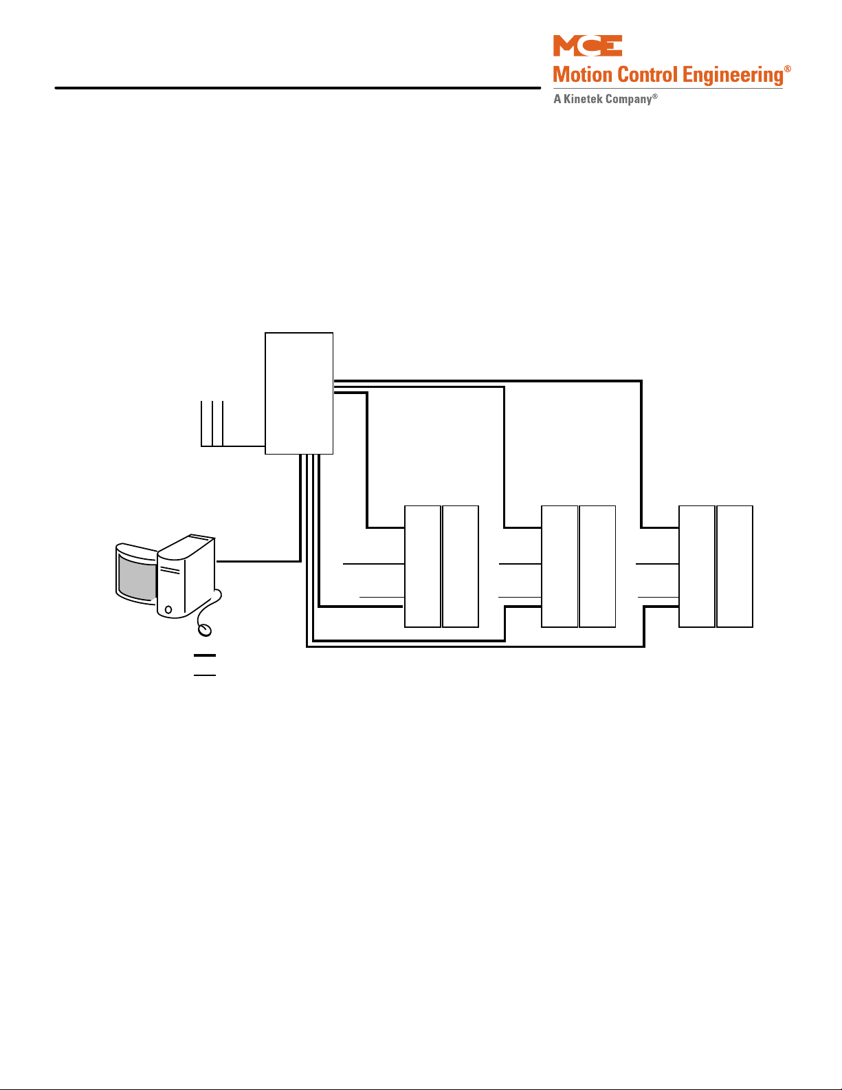
iControl Description
DISPATCHER
CAR CONTROL CAR CONTROL CAR CONTROL
SYSTEM: Hall calls, Parking, Special operating modes
iView
LAN: iView,
iMonitor,
iReport
Hall Calls
Car
Calls
Car
Calls
Car
Calls
Cartop Cartop Cartop
Ethernet
Other
LAN: iView, iMonitor, iReport Connectivity
System Interconnect Diagrams
It can be helpful to have a general understanding of the way the entire iControl system is interconnected.
• System Interconnection: Basic car control and dispatcher interconnections.
• iControl Interconnection: More detail for car controller interconnections.
• Cartop Interconnection: More detail for cartop interconnections.
• Dispatcher Interconnection: More detail for dispatcher interconnections.
Figure 1.3 iControl System Interconnection
1-4 Manual # 42-02-7223
Page 25
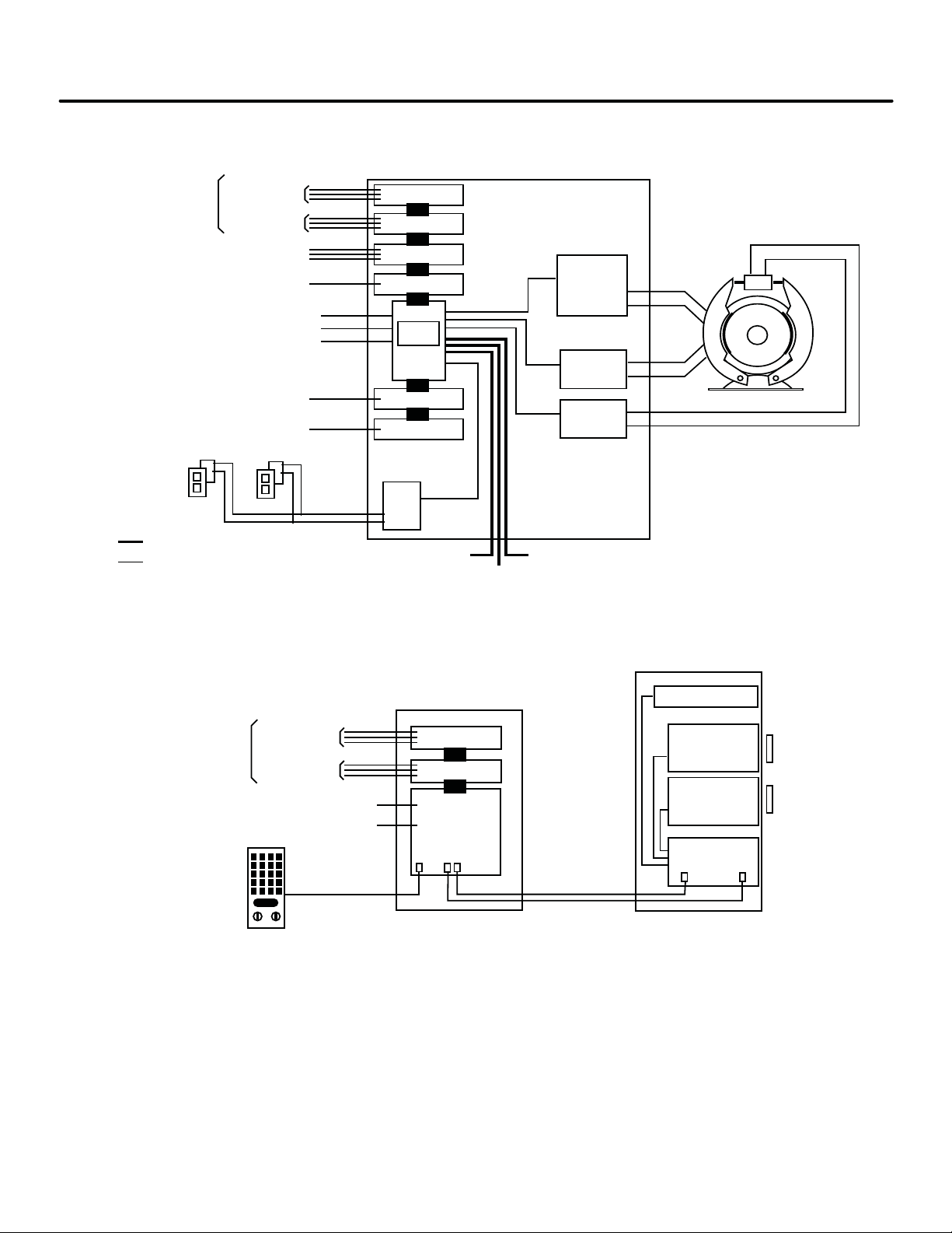
iControl DC
Ethernet
Other
Serial
Driver
Serial Hall Calls
Serial Bus
iBox
Rope Gripper
Rear Door
Inputs
Outputs
Serial Fixtures
OBD
Drive
Brake
Module
Motor
Module
Field Outputs
Field Inputs
Safeties
Limits
Cartop
Emergency Brake
Rear Door
Fixture Data
Earthquake
EQ String
Direct Connect (iView)
SYSTEM
LAN
iCONTROL
Discrete Hall Calls
(if not Serial Hall Call)
Inputs
Outputs Field Outputs
Field Inputs
Discrete Car Calls
(if not Serial Car Call)
Cartop Board
(ICE-CTP)
iLINK CARTOP BOX
iLAND LANDING SYSTEM
Serial Car Call
Sensor Board
Sensor Board
Signal Board
(LS-IPH)
Front
Rear (option)
Position Encoder
Serial Link
Serial links to iControl
Load Weigher
Landing Zone
magnet
Landing Zone
magnet
Figure 1.4 Car Control Interconnection
System Interconnect Diagrams
1
Figure 1.5 Cartop Interconnection
1-5
Page 26
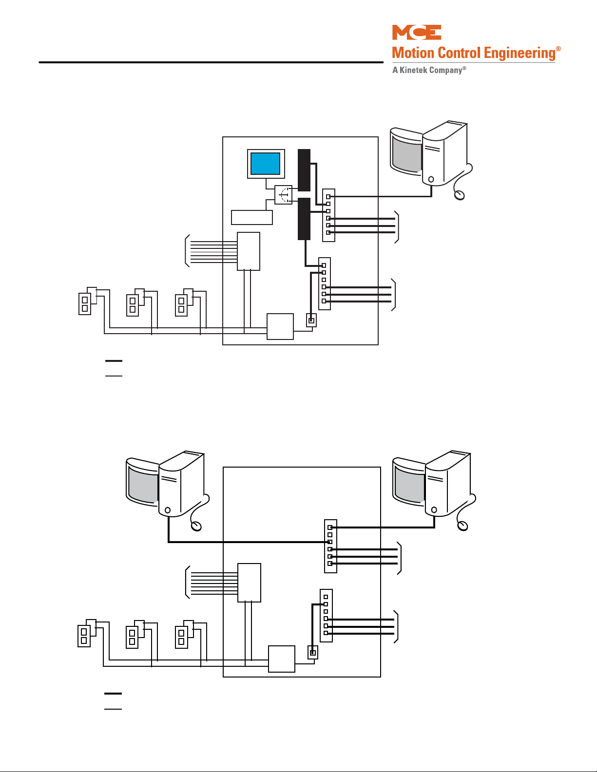
iControl Description
SYSTEM: Hall calls, Parking,
Special operating modes
LAN: iView, iMonitor, iReport
connectivity.
Ethernet
Other
DISPATCHER
Hall Calls
SYSTEM
LAN
To Cars
To Cars
iCue
Monitor
Switch
Keyboard
iView
Serial
Driver
Serial to
Ethernet
iMonitor or iReport
Serial Bus
SCION
General Field Inputs
to Dispatcher
SYSTEM: Hall calls, Parking,
Special operating modes
LAN: iView, iMonitor, iReport
(4 connections per car max.).
Ethernet
Other
Comm-connect Cabinet
Hall Calls
SYSTEM
LAN
To Cars
To Cars
iView
Serial
Driver
Serial to
Ethernet
iMonitor or iReport
Serial Bus
SCION
General Field Inputs
to Dispatcher
Figure 1.6 Central Dispatcher (iCentral) Interconnection
Figure 1.7 Local/Dispatcher (Comm-connect) Interconnections
1-6 Manual # 42-02-7223
Page 27

iControl DC
Installation Specifications
This section contains specifications pertinent to installing the controller.
Table 1.1
Installation Specifications
Topic Description
Controller dimensions
(floor mount)
iCentral cabinet
(floor mount)
iComm-Connect cabinet
(wall mount)
Machine room conditions 32 to 104 degrees F (0 to 40 degrees C), non-condensing. No installation on
Input power +/- 10% of job specification
Ground Direct, solid ground per NEC 250
Mounting Standard controller and iCentral cabinets mount to machine room floor
Conduit All connections to/from the controller must be in conduit per controlling local
NEMA 1:
Height = 62 inches (157.5 cm)
Width = 42 inches (107 cm)
Depth = 16 inches (41 cm)
Height = 72 inches (183 cm)
Width = 28 inches (71 cm)
Depth = 23 inches (58 cm)
Height = 26 inches (66 cm)
Width = 16 inches (41 cm)
Depth = 10.25 inches (26 cm)
carpet. No excessive vapors or dust.
according to controlling local and national codes. Local dispatching cabinet,
iComm-Connect is wall mounted.
and national codes. Control/low voltage wiring must be routed in separate
conduit from high voltage wiring. 1.5-inch diameter conduit is recommended
for the encoder cable so that the non-removable end connectors will fit
through.
1
1-7
Page 28

iControl Description
1-8 Manual # 42-02-7223
Page 29

In This Section
This section provides the information you need to install iControl and get the elevator running
in Construction Mode:
• Machine Room Preparation (see page 2-4).
• About MCE Job Prints (see page 2-6).
• Controller Cabinet Installation (see page 2-8).
• Equipment Grounding (see page 2-14).
• Check for Shorts to Ground (see page 2-16).
• AC Voltage Verification and Wiring (see page 2-17).
• Motor and Brake Wiring (see page 2-21).
• Tachometer or Encoder Installation (see page 2-23 or page 2-26)
• Safety String Wiring (see page 2-28).
• Applying Power (see page 2-30).
• LAN Connections (see page 2-30).
• Initial Parameter Settings (see page 2-43).
• Drive Startup (System 12 SCR Drive) (see page 2-47).
• Motor Field Calibration (System 12 SCR Drive) (see page 2-53).
• Running on Machine Room Inspection (System 12 SCR Drive) (see page 2-62).
• Drive Startup (Quattro DC Drive) (see page 2-71).
• Running on Machine Room Inspection (Quattro DC Drive) (see page 2-81).
Construction Mode
2-1
Page 30

Construction Mode
Danger
Before You Begin
Review the warnings and information in this section.
This equipment contains voltages up to 1000V, rotating motor parts, and driven machinery that can
cause serious or fatal injury. Only qualified personnel who are familiar with this manual and driven
machinery should attempt to start up or troubleshoot this equipment.
• USE EXTREME CAUTION — Do not touch circuit boards, resistors, or motor electrical connections without ensuring that the unit is properly grounded and no high voltage is present. Do not apply AC power before grounding the equipment in accordance
with applicable local codes, the job prints, and instructions contained in this manual.
• BE CERTAIN — that any possible violent motion of the motor shaft and driven
machinery will not cause personal injury or damage. Peak torques of up to ten times
rated motor torque can occur during a control failure.
• HIGH VOLTAGE — may be present on the motor and drive whether or not AC power is
applied, even if the motor is not rotating.
• BEFORE BEGINNING WORK — read these instructions. Become familiar with procedures. Proceed cautiously. These instructions assume adequate electrical troubleshooting experience. Follow procedures carefully and, if the elevator does not respond
correctly, obtain necessary assistance.
Overview of Construction Mode
Construction mode operation allows the car to be run on Machine Room Inspection and Cartop
Inspection with a bare minimum of field wiring. For Construction Mode operation, only the following are needed to run the car:
• Motor, brake, and drive
• Velocity encoder/tachometer
•Safety String
•Normal limit switches
• Door locks and door position monitor (if used)
• The Construction Mode option (iView > View > Setup> Safety > Configuration tab) must
be enabled to run the controller in Construction mode.
The cartop wiring interconnect box (iLink) is not required for Construction mode operation.
Instead, temporary wiring may be used to “bypass” the cartop safety string.
2-2 Manual # 42-02-7223
Page 31

iControl DC
Required Connections The following connections are necessary to run the car on Con-
struction Mode:
• Motor, Brake, and Drive
• Velocity Encoder or Tachometer
• SAFH, GOV, ESC, Rope Gripper (if enabled)
• SAFC (provide temporary Emergency stop switch between SAFH and SAFC if iLink is not
yet installed)
• UNTD and DNTD (Up and Down Normal Limit Switches)
• GS, DLMS, DLAT, DLAB, DPM (Verify the iView/Safety Configuration screen settings for
these options)
• INCT, ICTU, and ICTD
• Emergency Power Input
Connections not required for Construction Mode operation include:
• Cartop Communication (TX, RX)
• Quadrature signal (DP1, DP2)
•EQ signal
• Terminal Switches (U/DNTx and U/DETS)
•Fire Sensor
•DZ, ULM, DLM
In This Section
2
Please refer to “iBox Field Connections” on page 11-7 for definitions of iBox inputs and outputs.
Faults While operating in Construction Mode, faults may be generated due to incomplete installation. These may be disregarded in this phase and include:
• Invalid Front and/or Rear Doors
•Terminal Sync
• System Sync
•Floor Sync
2-3
Page 32

Construction Mode
Machine Room Preparation
When preparing the machine room for elevator controller installation, consider:
•Equipment location
• Machine room environment
• Ethernet and internet access
Equipment Location
When choosing equipment location, consider:
• Adequate working space for comfort and efficiency.
• Logical arrangement, taking into consideration other equipment in the machine room and
routing of electrical power, control, and Local Area Network (10/100 Base TX) wiring.
• Do not install equipment in a hazardous location.
• Installing a telephone in the machine room is desirable as it makes remote diagnostics and
adjustment assistance more readily available.
• Wiring the machine room for internet access will allow MCE technical support to use the
iView application to remotely view system parameters, diagnose problems, and assist you
in adjusting elevator controller settings.
• If any areas in the machine room are subject to vibration, they should be avoided or reinforced to prevent equipment from being adversely affected.
• Provide adequate lighting for the control cabinets and machines. A good working space
such as a workbench or table should also be provided.
Environmental Considerations
• Ambient temperature should remain within 32° to 104° Fahrenheit (0° to 40° Celsius).
Temperatures outside these guidelines may be tolerated, but will shorten equipment life.
Adequate ventilation is required. Air conditioning may be necessary.
• The air in the machine room should be free of excessive dust, corrosive elements, and
excessive moisture. A NEMA 4 or NEMA 12 enclosure can help meet these requirements if
machine room conditions are inadequate. If the machine room has open or unglazed windows or other direct outside openings, place equipment cabinets far enough from them so
that severe weather does not damage the equipment.
• Very high levels of radio frequency (RF) radiation from nearby sources should be avoided.
RFI may interfere with controller components, degrading elevator performance. Using
hand-held communication devices close to the controller may also cause interference.
Interference from permanently installed radio transmitting antennas is not common.
• Power line voltage fluctuation should not be greater than ±10%.
2-4 Manual # 42-02-7223
Page 33

iControl DC
Ethernet and Internet Considerations
The iBox supports three Ethernet connections:
• The 3 = PC port is for direct local connection of a laptop or desktop PC for elevator control
configuration, program uploading, system diagnosis, or parameter adjustment using MCE
iView software. Fixed IP address: 192.168.193.001
• For multi-car, centrally dispatched installations, the 2 = SYSTEM port provides dedicated,
fast 100 Base-TX connection between iBoxes. In these installations, the required Ethernet
hub is provided by MCE and mounted in the iCentral cabinet. See the table below for the
factory default.
• The 1= LAN port allows the elevator controller to be connected to a 10/100 Base-TX Local
Area Network (if available). This allows a single PC to be used to administer and monitor
multiple elevator controllers using iView software. See the table below for the factory
default address for this port.
Through a net modem, ISDN, DSL or other internet access, this port may provide remote
access to the controller. This access allows MCE technical support staff to view controller
parameters at the same time you view them through your LAN or direct/local connection.
Elevator parameters are protected from meddling or accidental change because in order to
write data to a controller, permission must be granted in the machine room.
Machine Room Preparation
2
For installations not requiring a central dispatching capability or for single car installations,
Ethernet or internet connectivity may not be required.
If you want to take advantage of Ethernet or internet connectivity benefits, the machine room
must be appropriately wired. Most commercial buildings use Ethernet Local Area Networks
that can readily be extended to accommodate machine room access.
Table 2.1 System, LAN, & 3=PC TCP/IP Addresses
Hub Group
System all 192.168.192.201-202 1-20 192.168.192.001-020 192.168.192.211-214
LAN A 192.168.191.201-202 1-20 192.168.191.001-020 192.168.192.101-200*
LAN B 192.168.191.203-204 1-20 192.168.191.021-040
LAN C 192.168.191.205-206 1-20 192.168.191.041-060
LAN D 192.168.191.207-208 1-20 192.168.191.061-080
LAN E 192.168.191.209-210 1-20 192.168.191.081-100
Port #3 = PC (iBox ONLY), NO HUB 192.168.193.001
*192.168.191.101 is typically used for the iView PC.
Group IP, Primary
& Backup
Car ID Car IP
System/Serial
Hall Call Bus 1 - 4
iView PC
2-5
Page 34

Construction Mode
Note
Car Number*
Job Number
Page Number**
* Car Number “G” = Group Controller
** Page Number “D” = Drive Page, CT= iLink
** An “X” after the page number = auxiliary page
About MCE Job Prints
MCE Job Prints are technical drawing and instruction sets specifically generated for and
accompanying each MCE installation. The job prints provide technical information and instruction specific to the installation using the survey information collected when the job was specified. Job prints are frequently referenced in installation instructions.
Become familiar with the following information as well as the wiring prints provided with this
control system.
Drawing Number Format - Each
print has a drawing number in
the title block. The drawing number contains the job number, car
number and page number (see
examples). In this manual the
drawings will often be referred to
by the last digit of the drawing
number (page number).
2003012345-2-1
Drawing Name: Some drawings have a drawing name directly above the title block or at the top
of the drawing. The drawing name may also be used to refer to a particular drawing.
MCE job print drawing numbers use the format “Job Number — Car Number — Drawing Identifier.” Thus they are specifically “keyed” to particular installations. It makes using and understanding job prints much easier if you take some time to review the job prints package before
beginning controller installation. Drawing identifiers and the information you can expect to
find on that job print drawing are listed below:
• N: Nomenclature drawing — schematic symbols, wire gauge information, circuit board
names and symbols.
• INT: iLink cartop wiring interconnect box to controller connections.
• CVR: iBox controls and indicators.
• 1: AC power connections, power bus information.
• 2 through nn: iBox/controller wiring.
• CC: Contact Count drawing — System contact/relay information.
• SH: Serial Hall Call wiring.
• CT: Cartop wiring (iLink cartop wiring interconnect box).
• CW: Traveling Cable Wiring
• F: iDC Filter (remote)
• COP: Car Operating Panel to cartop box (iLink) wiring.
• CW: Car to cartop box (iLink) wiring.
• MRW1, -MRW2: Machine Room and Hoistway wiring.
• D1, -D2, -D3, -D4: Controller and drive wiring.
•GND: Grounding
2-6 Manual # 42-02-7223
Page 35

iControl DC
Note
• PI: Peripheral Interface (iView, iMonitor)
• IP: IP Address Scheme
About MCE Job Prints
Depending on your installation, you may have extra sheets of particular drawings. Extra sheets
are indicated by an “x” following the drawing identifier. You may also have different or additional equipment in your installation accompanied by different or additional drawings in your
job prints. In any case, take the time to become familiar with the job prints before beginning
work.
Symbols
Every job print set contains a drawing depicting and describing schematic and other symbols
used in the job prints. Review this page to acquaint yourself with symbols and their meanings.
Nomenclature
The following table lists MCE part numbers and provides a brief description for each. Your
installation may not use all boards listed.
Table 2.2 Component Nomenclature
Symbol Component Description
00 ICE-IMP iBox primary microprocessor board.
01 ICE-SAF iBox safety board.
02 ICE-IRB iBox Relay board.
03 ICE-IEQ Earthquake and counterweight derailment sensor board.
04 ICE-SF-X Serial Fixtures interface board (displays, annunciators, etc.).
05 ICE-IRD Rear Door board.
06 ICE-RG Rope gripper board. Used when a rope gripper is supported.
07 ICE-COP Serial Car Operating Panel board.
08 ICE-CTP iLink (Cartop) primary microprocessor board.
09 ICE-EB Em ergency Brake Board
32 ICE-MIAC Input expansion board. Used as needed in iControl and the iLink cartop box to
support equipment inputs.
50 ICE-MOT Output expansion board (not currently used).
51 ICE-MOR Output expansion board. Used as needed in iControl and the iLink cartop box to
support equipment outputs.
80 ICE-LCB Low Current Brake board, used in low current braking applications.
85 SC-ION Serial Control I/O Node board.
2
2-7
Page 36

Construction Mode
Note
Caution
Controller Cabinet Installation
Review the wiring guidelines in this section before bringing wires into the controller.
When drilling or cutting access holes or during other machining, do not allow any metal
chips to fall into the electronics. Keep drive or other covers in place while wiring to prevent
damage to components.
1. Mount cabinets securely to the machine room floor.
2. Cut holes to permit bringing wires in as shown in the following illustration.
MCE applies labels inside the cabinet to identify suggested wiring hole locations. The MCE controller cabinet does not require rear access.
• Field wiring should enter the cabinet from the side at the lower left corner or from the bot-
tom directly under the wiring trough. The wires must be routed through the wiring
trough on the left side of the controller cabinet in a way that allows the power
box door to open fully.
• All conductors entering or leaving the controller cabinet must be through conduit. High
voltage, high current conductors, such as power conductors from the fused disconnect or
isolation transformer, must be separated from control wires. It is essential that Tachometer/Velocity Encoder control wires be routed through a separate conduit away from high
current conductors.
• The traveling cable must have at least four twisted shielded pairs to be used for the position pulser quadrature signal and the iL
sor board (ICE-CTP) to the iBox Safety Processor board (ICE-SAF). The shielded cable
should be used all the way to the controll er. I f there are more shielded pairs still available,
route the ULM, DLM and DZ signals from the iLink Car Top Processor board through a
shielded pair (especially if the building has more than eight floors). The shields must be
grounded at both ends by connecting them to a “SHLD” terminal.
INK communication link from the Car Top Proces-
2-8 Manual # 42-02-7223
Page 37

iControl DC
Note
System 12 SCR
Drive
(Note: Quattro
DC Drive is
supplied in a
separate cabinet)
Input / Output
boards
M
Contactor
Resistors
Wiring Trough - (field wiring goes here)
Preferred cable access hole locations
iPower box
Figure 2.1 Cable Access
Controller Cabinet Installation
2
PC boards can be easily damaged by electrostatic discharge (ESD). Use a properly grounded wrist strap or
other static protection when handling, touching, or
making connections to PC boards.
2-9
Page 38

Construction Mode
System 12 SCR Drive
(Note: Quattro DC
Drive is supplied in
a separate cabinet,
see next page)
iBox Panel
ICE-MOR: Outputs
ICE-MIAC: Inputs
ICE-SF: Srl. Fixtures
ICE-EQ: Earthquake
ICE-SAF: Safety Processor
ICE-IMP: Main
Processor
Contactor
Resistor Cabinet
Field wiring for hoistway,
car, landing and load
weighing systems, and discrete hall calls are on the
left edge of the controller.
High voltage connections
are primarily on the right
side of the cabinet under
the DC drive (and in a
separate cabinet for the
Quattro drive).
Outputs used to drive
customer peripherals.
Signal/Pin assignments
made in iView screens.
Serial fixture interface.
Floor indicators, etc.
Earthquake sensor I/O.
Tachometer , position
encoder, velocity encoder ,
and serial link from cartop
processor.
Discrete car connections,
limit switches, hoistway,
and door system connections.
Safety I/O.
Spare I/O. Common,
120VAC, and 110VDC
buses.
Motor contactor
wiring.
AC connections.
ICE-IRB:
ICE-MIAC: Inputs
Customer peripheral
inputs (card readers,etc.) Signal/Pin
assignments made in
iView screens.
Emergency Brake
connection
Rear door processing
ICE-RG Rope Gripper
ICE-IRD Rear Door
Overview of Typical Connection Locations
The following diagram provides a general overview of component and connection locations
inside iControl. Because circuit boards in iControl are connected along a common bus, they may
be arranged differently or different boards may be used in different installations. This is only a
general overview. Use it in conjunction with the job prints when making electrical connections.
Please refer to “iBox Field Connections” on page 11-7 for a list of specific inputs and outputs.
2-10 Manual # 42-02-7223
Page 39

iControl DC
3-Phase
Input Power
Motor Field
Controller (A24)
UTM
PCM
Line Side Converter
Optional
Dynamic Braking
Resistors
Control
Power Fuses
(F1 & F2)
Control Power
EMI Filter
Motor
Electrical
Control Board
Bus Discharge
Relay
Motor Side Inverter
and Control
Electronics
Cooling Fans
Optional Low Voltage
Field Supply or optional
Field Filter
Quattro Drive Component Locations
Controller Cabinet Installation
2
2-11
Page 40

Construction Mode
Power Bus
Input
Peripheral or
COP switch
Output
Power Bus
Peripheral Inputs and Outputs
In every installation, there are different requirements for accepting inputs from or providing
outputs to various kinds of peripheral equipment. iControl handles this generic need using ICEMIAC input boards, ICE-MOR output boards, and ICE-COP and SC-ION serial I/O boards.
Typically an installation will have at least one MIAC and one MOR board in the controller cabinet to handle requirements local to the machine room and at least one MIAC and one MOR
board in the cartop interconnect box (iLink) to handle requirements local to the elevator car.
Inputs Refer to your job prints (drawings -9 — nn or -CT) to see exactly how your peripheral inputs are configured. Typical usages include car call buttons, card reader inputs, fire return switches, smoke sensors, etc. To complete an input, the installer wires a switch or contact closure provided by the peripheral equipment between a power bus (120 VAC) and one of the ICE-MIAC board input connections. Exact requirements are collected during the job survey and documented in the job prints. The illustration below shows a typical switch wiring example.
Figure 2.2 Typical Peripheral Switch Connection to ICE-MIAC Board
Outputs Refer to your job prints (drawings -9 — nn or -CT) to see exactly how your out-
puts are configured. Typical usages include in-service lights, emergency power lights, nudging
buzzers, floor chimes, car-riding lanterns and chimes, and car call button indicators (lights). To
complete an output, the installe r wi res the lamp, buzzer, etc. between a power bus and one of
the ICE-MOR output connections. Exact requirements are collected during the job survey and
documented in the job prints. Different blocks of outputs may be connected to different buses.
The illustration below shows a typical (lamp driving) output wiring example.
Figure 2.3 Typical Peripheral Lamp Connection to ICE-MOR Board
2-12 Manual # 42-02-7223
Page 41

iControl DC
#1
#16
#17
#32
Input/Output Terminals Input/Output assignment may be changed in the iView application but, the job prints specify, and the system is shipped supporting, a logical configuration. For example, the #1 floor button in the car operating panel is connected to the #1 input to the cartop ICE-MIAC board. When the button is pressed, the input signal directs the controller to register a call to floor #1 and the controller activates the #1 output on the cartop ICE-MOR board. The active output completes a circuit and the lamp in the #1 button is lighted so that the passenger knows the call has been registered.
The correlation between input and output is assigned at the factory according to the job survey
and the correct wiring is stipulated on the job prints. It is imperative that, if any changes or
additions are made, MCE be contacted so that the job prints may be updated to reflect current
connections.
Input/Output Wiring Inputs and outputs are wired to pluggable terminals on the cartop or controller ICE-MIAC (inputs) and ICE-MOR (outputs) boards. The connector numbering is the same on input and output boards. Terminal arrangement is shown in the illustration below.
Figure 2.4 ICE-MIAC and ICE-MOR Connector Assignments
Controller Cabinet Installation
2
2-13
Page 42

Construction Mode
ACCEPTABLE
ACCEPTABLE
NOT ACCEPTABLE
Equipment Grounding
For good grounding, quality materials and methods must be used. Grounding must conform to
all applicable codes. Proper grounding is essential to safety and reduces noise-induced problems:
•Provide equipment grounding in accordance with NEC Article 250 and/or the local electrical code, as applicable.
• The grounding wire between equipment cabinets may follow a branching or daisy-chain
configuration but the wire must terminate at the last controller and NOT loop back.
• You must provide a direct, solid ground to the controller and motor. An indirect ground,
such as the building structure or a water pipe, may not provide proper grounding and
could act as an antenna — radiating RFI noise and interfering with electronic equipment
in the building.
• The conduit containing the AC power feeders must not be used for grounding.
Figure 2.5 Controller Cabinet Ground Wiring
2-14 Manual # 42-02-7223
Page 43

iControl DC
Note
Note
Drive Isolation Transformer
SCR Drive
Input
Power
Ground
Output
Ground
Note: Grounding of the WYE secondary of
the Drive Isolation T ransformer should be
accomplished according to the drive
manufacturer recommendation.
Delta
Wye
Ground
Ground Lug in the MCE Controller
Cabinet
Building Ground
DC Motor
Ground
Figure 2.6 Isolation Transformer, Drive, and DC Motor Ground Wiring
Equipment Grounding
2
The grounding instructions provided in the job prints are specific to your job and are the controlling document if any question arises.
If your installation includes the Magnetek Quattro DC drive, which is housed in a separate cabinet, please observe the instructions under Grounding considerations in the Quattro DC
Elevator Drive Technical Manual.
2-15
Page 44

Construction Mode
Danger
Caution
Check for Shorts to Ground
Check for shorts to ground before powering up the system. Power must be OFF at the main
disconnect. If any shorts to ground are discovered, they must be corrected before proceeding.
A short to ground is defined as having a resistance of less than 20 ohms between the 1 bus
(Common) and the terminal being tested.
Be certain that power is OFF at the main disconnect before proceeding.
Typically, the iLink cartop box has not been installed at this point. If the cartop box has been
installed and connected, it MUST be disconnected before checking for shorts in the controller cabinet. This is easily done by simply unplugging all field-wired connectors in the cartop box before
checking for shorts to ground.
1. Using a standard screwdriver, temporarily disengage all fuses at the top of the iPower
box by turning them counterclockwise until they pop up. Don’t place a cap on a fuse
holder without a fuse in it. The cap can get stuck and be hard to remove.
2. Disengage all fuses at the bottom of the iBox (just below the logo).
3. Release the screws that hold the iPower box closed and open the enclosure. Disengage all the fuses from the fuse block inside (towards the top of) the iPower box by lifting them clear of their sockets at one end.
4. Measure the resistance between the iBox #1 (Common) bus and terminals that have a field connection (DZ down to SP4 on the left side of the iBox).
5. Measure the resistance between the #2 (120VAC) bus terminals and the #1 bus.
6. Measure the resistance between the #3 (110VDC) bus terminals and the #1 bus.
7. Check for shorts to ground on motor power terminals L1, L2, and L3.
8. Check for shorts to ground on brake terminals B1 and B2.
9. If no shorts to ground are discovered, re-engage the fuses. Refer to the job prints for fuse location if necessary.
2-16 Manual # 42-02-7223
Page 45

iControl DC
Note
AC Voltage Verification and Wiring
Instructions in this section describe wiring from commercial power to iControl. Most of the
technical information is in the MCE job prints and referenced here as necessary. As shown in
the job prints, an isolation transformer may be used to clean up “dirty” commercial power, shift
voltage levels, and prevent noise from electrical equipment from being introduced back into the
building power system. Isolation transformers are specified in some, but not all, installations.
AC voltage verification and wiring instructions include:
• Verifying main line power and wiring the controller
•Initial power up
All conductors entering or leaving the controller cabinet must be through conduit. High voltage,
high current conductors, such as power conductors from the fused disconnect or isolation
transformer, must be separated from control wires. It is essential that tachometer/velocity
encoder control wires be routed through a separate conduit away from high current conductors.
AC Voltage Verification and Wiring
2
Incoming power to the controller and outgoing power wires to the motor must be in their
respective grounded conduit.
The majority of iControl installations use an iField Brake Module to provide selective voltages
to precisely control brake picking, brake hold, brake application, and brake timing. DC installations may also use auxiliary power inputs. In these cases, the job print details for AC input wiring from the transformer may include connections specifically for auxiliary brake and input
power. Read and follow the job prints carefully.
2-17
Page 46

Construction Mode
Note
Caution
Verifying Main Line Power and Wiring the Controller
1. Consult the job prints. Check the line side of the main disconnect to see that all three
legs are at the correct voltage. Compare this voltage with the primary voltage on the data
plate for the drive isolation transformer (must be within 10% of this value).
Proper motor branch circuit protection in the form of a fused disconnect switch or circuit
breaker must be provided for each elevator according to applicable electrical code. Each disconnect or breaker must be clearly l abeled with th e elevator number. The electrical contractor must
determine the wire size for the main AC power supply and for the wiring from the di sconnec t or
breaker to the drive isolation transformer.
2. If the car is part of a group, the cars in the group must be wired to provide power to the
group cabinet. If this is the case, refer to the Group Supervisor Field Wiring print in the
job prints. Group power is provided by the car controllers as shown in drawing -2. The
main AC power supply wiring size must be determined by the electrical contractor.
2a. Check the phase-offset of the individual car ST2-bus lines before connecti ng them
to the Group cabinet. Use a voltmeter set to AC volts to measure between adjacent
car ST2-bus terminals in the Group cabinet. The meter must read less than
10VAC. If the reading is higher, reverse the power leads going to the car T1 transformer at L1 and L2 and measure again.
All 2 bus power from car to Group cabinets must be in phase. Connecting out-of-phase power
WILL cause damage.
2b. A separate conduit or wiring trough must be provided for the System (car-to-car)
Ethernet network. Wiring is fully detailed in the job prints. These details must be
followed exactly.
2c. If applicable, also wire according to the Group Interconnects to Individual Car
Cabinets print. Be sure to ground all cabinets according to instructions.
2d. Refer to the iCentral (Group Supervisor) Field Wiring Print for Group Controller
field wiring instructions.
3. Connect AC supply wiring to the isolation transformer, and wiring from the transformer to the controller exactly as shown in the job prints.
2-18 Manual # 42-02-7223
Page 47

iControl DC
Caution
Note
Initial Controller Power Up
After AC power is connected, temporarily power up the controller and check to see that power
buses inside the controller cabinet are providing proper outputs.
This procedure assumes that no field wiring has been connected to the controller. If field wiring has
been connected, disconnect it before beginning this procedure. Before applying power, physically
check all power resistors and other components located in the resistor and controller compartments.
Components loosened during shipment may cause damage.
1. On the iBox, verify:
• Inspection switch UP (Inspection mode selected)
• Controller Stop Switch DOWN (Stop selected)
• Test switch ON
• All other iBox slide switches DOWN (Off)
These switch settings prevent the elevator from moving when the controller is powered up.
AC Voltage Verification and Wiring
2
NOT FUNCTIONAL
The controller microprocessor board has battery backup for logic retention. An insulator prevents the battery from discharging during shipment. Remove the insulator now if has not
already been done.
2-19
Page 48

Construction Mode
1
-15
+15
GND
+5
#1 is the system common bus
2. Power up the controller. The system will take about 60 seconds to boot.
3. If the controller fails to power up, refer to the job prints and check supply connections and fuses.
Inside the controller cabinet, 120VAC and 110VDC output buses are presented at the lower left
corner of the iBox as shown in the illustration below.
4. Measure from any #2 bus terminal to a Common (#1) terminal and verify 120VAC (+/10%).
5. Measure from any #3 bus terminal to a Common (#1) terminal and verify 110VDC (+/10%).
-1
-1
-1
-1
-2PI
-2PI
-2
-2
-3HA
-3HA
-3
-3
COM120 VAC110 VDC
Power for PC board circuitry is provided through a 5-position, pluggable connector on the right
side of the iBox (near the Computer and Drive Reset buttons) as shown below.
6. Measure from each of the voltage terminals to GND to verify -15VDC, +15VDC, and
7. If any bus voltage is missing, check the associated fuse. The fuses are labeled with the
8. Check voltages at panel mounted terminals L1X, L2X, and L3X (if present).
9. Check voltages:
• on the System 12 SCR Drive - at terminals X1, X2, X3, and Y1, Y2, and Y3.
• on the Quattro DC Drive - at terminals L1, L2 and L3.
10. Power the controller down (in preparation to continue wiring equipment).
2-20 Manual # 42-02-7223
+5VDC respectively (+/- 2%). Note: Place meter on AC range and check each supply to
ensure AC voltage does not exceed 0.050 VAC.
bus numbers and are located at the top and bottom of the iBox.
They must be within -5% to +8% of the value shown on page -SCR (or -D1) of the job
prints. If they are not, contact MCE Technical Support.
Page 49

iControl DC
DC Hoist Motor, Brake, and Encoder/Tachometer
DC Hoist Motor, Brake, and Encoder/Tachometer
This section describes:
• Checking the hoist motor for insulation breakdown or shorts
• Wiring the hoist motor to the controller
• Wiring the iField motor field module
• Verifying brake resistance and wiring the brake
• (Optional) brake pick switch installation and wiring
• Installing the velocity encoder
Checking the Hoist Motor
If this job reuses existing rotating equipment, the equipment must be checked for insulation
breakdown.
1. Disconnect all motor and brake wiring.
2. Perform an insulation test between these wires and the frame of the related equipment using a Megohm meter to subject the insulation to the same high voltages that would be present during operation.
3. Minimum insulation resistance of 100k Ohms is required.
4. Correct any insulation problems before proceeding. Insulation problems may indicate a serious problem in the equipment.
2
Wiring the Hoist Motor to the Controller
Incoming power to the controller and outgoing power wires to the motor must be in their
respective grounded conduit.
Keep DC motor wires separate from control wires both inside and outside the controller cabinet. Encoder or tachometer wiring must use a separate grounded conduit.
1. Refer to job print drawing -D1 for DC drive connections to rotating equipment.
2. Make connections as shown:
• on the System 12 SCR Drive - be certain to follow schematic notes regarding wire size
and specific motor connections.
• on the Quattro DC Drive - follow the instructions in the section titled EMC Compliance
in the appendix of the drive technical manual.
Wiring the iField Motor Field Module
(Quattro DC Drive: Refer to job print drawing -D1 for motor field wiring)
1. Measure the resistance of RM in the iPower box (the enclosure the iBox is mounted to). Verify that it is set according to the job prints.
2. Connect motor field leads from the motor to MF1 and MF2 terminals below the iBox as shown in the job prints.
2-21
Page 50

Construction Mode
Note
The controller i Power
box release screws
are in the top and
bottom right corners
of the enclosure. Door
must remain closed
during operation.
RB is a large,
ceramic resistor with
a center tap.
Loosen and slide
the center-tap
ring to change
resistance.
RB is in this area
Verifying Brake Current Resistance
High current brake systems use a brake (iField) module.
1. With brake leads disconnected from the controller, measure resistance through the brake coil.
2. Inside the controller cabinet, locate the screws, one at the top and one at the bottom
right corner of the iPower box (the enclosure the iBox is mounted to). Turn the screws
counter-clockwise to their stops and open the enclosure (it is hinged on the left).
3. Refer to job print drawing D2. Toward the right-top of the enclosure, locate the large ceramic resistor labeled RB.
4. Check the resistance across RB. As an initial working value, RB resistance should be about three times (3 X) the resistance measured across the brake coil.
During adjustment, the resistance across RB may be further adjusted to achieve smooth brake
setting. Refer to job prints for instructions.
5. If necessary, adjust RB resistance by loosening and sliding the center-tap up or down. When the resistance is correct, retighten the center tap.
2-22 Manual # 42-02-7223
Page 51

iControl DC
Note
Caution
DC Hoist Motor, Brake, and Encoder/Tachometer
Wiring the Brake
• Refer to job print drawing D2. Connect brake
wires to terminals B1 and B2 located just below
the iPower box.
Brake wires must not be routed in the same conduit
with DC motor wires or velocity encoder wires.
Tachometer or Encoder Installation and Wiring
A tachometer or a velocity encoder may be used.
Table 2.3 Selecting a Tachometer or a Velocity Encoder
Machine Device Shaft Mounting Brake Drum Mounting Sheave Mounting
Geared Tachometer Yes No No
2
Encoder Yes 1024PPR No No
Gearless Tachometer No Yes Yes
Encoder Yes 12,700PPR Yes 1024PPR Yes 1024PPR
Tachometer
(If you are using a velocity encoder, please see the next topic.) When installing a tachometer, do
not mount it near a magnetic field (for example, the motor field coils). Magnetic fields may
cause the tachometer to report incorrect speeds. Note also that any vibration caused by the
tachometer cannot be corrected inside the drive. The tachometer wheel and the surface on
which it runs must be smooth and the tachometer must be mounted so that it can maintain contact without binding or bouncing.
Alignment of the tachometer coupling is extremely important. Most vibration problems are
caused by the tachometer or the way in which it was mounted. The tachometer mounting must
be rigid and the tachometer wheel must be aligned precisely with the surface it is running on
(i.e., the brake drum or drive sheave).
In geared applications, do not drive the tachometer from the sheave because gear lash cannot be
compensated by the drive unit.
2-23
Page 52

Construction Mode
Note
0
Brake drum or drive sheave
Tachometer (held against the rotating surface by its own weight)
Tach wheel
Hinge and bracket (hinge
must be excellent quality
with very little slack)
Typical Tachometer Mounting The following illustration shows a typical tachometer mounting arrangement. Mounting without a hinged assembly is all right as long as the tach wheel can be turned by hand at any point in the machine rotation and does not become too loose or too tight at any point.
Figure 2.7 Typical Tachometer Mounting
The surface on which the tach wheel rides must NOT be out-of-round. Distortion will cause
poor control and oscillation.
DNAI2765 R
2-24 Manual # 42-02-7223
Page 53

iControl DC
Note
iBox Connection End
Insulate shield at
tachometer end -Do not connect the
shield to the tach.
Tachometer Wiring
The tachometer wiring must use a separate grounded conduit. Inside the controller cabinet, if
control wires must cross power wires, they must cross at right angles to reduce the possibility of
interference.
The cable must be routed into the controller cabinet in a separate conduit. The following illustration shows the wiring at the controller end.
Figure 2.8 Tachometer Wiring
DC Hoist Motor, Brake, and Encoder/Tachometer
2
1. Connect the cable from the tachometer as shown above.
2. The connection to the controller TS connection must be positive (+) with respect to the TC connection when the elevator is moving in the up direction.
3. DO NOT connect the cable shield at the tachometer end of the cable. Insulate any part of
the shield exposed at the tachometer end to prevent it from accidentally shorting to
ground. (Connecting the shield at the tachometer end may cause ground loop noise and
affect ride quality.)
2-25
Page 54

Construction Mode
Note
Hoist motor
9-pin D
Connector
Isolator
bushing
Velocity Enco der
Hoist motor
shaft
Typical mounting
bracket
Velocity
Encoder
Phenolic
isolator
Flexible coupling
Hoist motor shaft
Velocity Encoder Installation and Wiring
(If you are using a tachometer, please see the preceding topic.) The encoder must be mounted
and wired according to the drawings. When installed, the encoder must be electrically isolated
from the motor or any other ground. (Resistance between the encoder casing and the motor or
other ground should be “infinite.”)
Do not mount the encoder or its wiring close to a magnetic field (the motor or brake coils). Magnetic fields can induce AC into the encoder signal, producing erratic control at lower speeds.
Encoder wiring must use a separate, grounded conduit. Inside the controller cabinet, if control
wires must cross power wires, they must cross at right angles to reduce the possibility of interference.
Encoder Mounting The following illustration shows two typical encoder installations.
Figure 2.9 Typical Encoder Installations
2-26 Manual # 42-02-7223
It is very important that the encoder does not slip, wobb le, bounce, or vibrate due to poor installation of the shaft extension, coupling, or encoder mounting. It is also important that the
encoder housing be electrically insulated from the motor, machine, or other ground if the
encoder is manufactured by BEI. An insulated encoder mount has been furnished with the BEI
encoder. However, this type of mounting may not be practical for all applications, therefore, the
best method for mounting the encoder and coupling it to the motor must be determined at the
job site.
Page 55

iControl DC
Note
Caution
Quadrature
data from
encoder
Drain/Shield
Power to
encoder
iBox
Purple
Gray
Green
Blue
Black
White
Encoder Isolation The encoder housing must be electrically isolated from the machine (ground). To check this:
1. Measure the resistance between the encoder case and the frame of the motor. The mea-
DC Hoist Motor, Brake, and Encoder/Tachometer
sured value must be “infinite” for complete isolation.
Encoder Wiring A shielded cable with an appropriate connector at the encoder end is provided. The controller end of the cable exposes trimmed and tinned individual conductors. The encoder cable must be routed into the controller cabinet in a separate conduit. The following illustration shows the encoder wiring at the controller end of the cable.
These connections are shown for illustration purposes only. Follow the job print instructions
for your specific encoder connections — they may be different than those shown here. Z+ and Zconnections are rarely used at the controller-end.
2
1. Connect the cable to the encoder using the cable/connector provided.
2. Route the cable through a separate conduit to the controller cabinet.
3. Connect the controller end of the cable as shown in the job prints.
4. Verify that the encoder shield is soldered to the drain wire (wire without insulation). Keep the cable shield connection as short as possible — connect it to the nearest shield terminal.
The encoder used must be rated up to 15-volts.Do not coil excess Encoder cable near high voltage
components — noise may be induced. If the cable must be shortened, trim it at the controller end. Do
not cut and re-splice in the middle of the cable or shorten at the Encoder end.
2-27
Page 56

Construction Mode
Note
Basic Safety String and Associated Wiring
This section contains wiring instructions for basic safety string switches (in Construction Mode,
before the iLink cartop interconnect is installed). A safety string is essentially a number of normally-closed switches connected in series such that, should any one of the switches open, power
to the motor and brake will immediately drop to stop the car. The elevator must not be run until
the safety string is connected. Safety string wiring includes:
• Emergency Stop switch
• Hoistway safety switches
• Cartop safety CTS Relay temporary bypass (for Construction Mode use only)
The location and number of safety switches varies from job to job. MCE job prints indicate exact
job wiring as determined during the job survey. Please refer to “Safety String Bypass Jumper”
on page 6-3 for safety bypass related information.
Cartop Safety Switches
Depending upon the job, cartop safety switches may include:
• Safety Clamp Switch
•Emergency Exit Contact
•Emergency Stop Switch
•CTS Relay (iLink)
The wiring instructions for these switches are on the job prints.
1. Refer to the job prints.
2. Wire the cartop safety switches as shown.
The Cartop Safety Relay is located in the cartop interconnect box. If the box is not yet installed,
the relay must be temporarily bypassed to get the car operating in construction mode. For now,
using the switches and terminals available to you, wire as much of the string as you are able.
Hoistway Safety Switches
Depending upon the job, hoistway safety switches may include:
•Final Limit Switches
•Buffer Switches
•Pit Door Switch
•Pit Stop Switch
•Governor Switch
The wiring instructions for these switches are on the job prints.
1. Refer to the job prints.
2. Wire the hoistway safety string switches as shown.
2-28 Manual # 42-02-7223
Page 57

iControl DC
Danger
ICTD
ICTU
3
3
DOWN
INCT
INSPECTION
SAFE
UP
Insp
Norm
Temporary CTS Relay Bypass
If the iLink cartop interconnect box which contains the Cartop Safety (CTS) Relay is not yet
installed, you must bypass the CTS relay temporarily (for Construction Mode only). (If you are
installing the iLink cartop box now, please refer to the iLink instructions in Section 3.)
Basic Safety String and Associated Wiring
1. Refer to the job prints.
2. Connect the safety string in series between the iBox SAFH and SAFC terminals.
3. You must provide an Emergency Stop switch in series between SAFH and SAFC.
Make sure the Emergency Stop switch is wired in series between SAFH and SAFC to allow emergency
stopping while working on the cartop.
Access Locks and Contacts
Door switches include:
• Car door: GS (Gate Switch).
• Hall doors: DLMS (Door Lock Main String), DLAT (Door Lock Access Top), DCAT (Door
Contact Access Top), DLAB (Door Lock Access Bottom), DCAB (Door Contact Access Bottom).
1. Refer to the job prints.
2. Connect the switches for front and rear (if present) doors as shown.
Rope Gripper Wiring
An “emergency brake” may be connected between iControl terminals RG1 and RG2 to stop
unexpected car motion. A rope gripper is used to apply braking pressure to the hoist ropes.
After it is triggered, press the iBox Fault Reset button or the Rope Gripper board reset button to
reset the rope gripper.
2
1. Refer to the job prints (MRW- machine room wiring sheets).
2. Connect the rope gripper to iControl RG1, RG2, RG5, and RG7 terminals as shown.
Temporary Rope Gripper Bypass
If a Rope Gripper will be installed later, you may temporarily bypass the input by installing a
jumper between RG5 and RG7.
Temporary Cartop Inspection Wiring
Four cartop switches control car motion: An
Inspection Enable switch, a Safe switch , an Up
switch, and a Down switch.
1. Refer to job print drawing -CW, Cartop Inspection Station.
2. Connect the (Normally Closed) Cartop Inspection Enable switch between the #3 bus and the iControl INCT terminal as shown. (This switch is used to put the car on cartop inspection. INCT is active low.)
2-29
Page 58

Construction Mode
Note
3. Connect a Safe push button switch between the #3 bus and the direction push buttons.
4. Connect a Down push button switch between the Safe switch and the iControl ICTD terminal as shown (active high).
5. Connect an Up push button switch between the Safe switch and the iControl ICTU terminal as shown (active high).
Applying Power
1. Set the iBox Inspection switch to the Inspection position.
2. Set the Controller Stop switch to the Stop position.
3. Set the Test switch to On.
4. Turn on power at the main disconnect.
5. Watch the front panel displays of the iBox, the controller will take about 60 seconds to initialize.
6. Check the iBox Computer, Safety A, and Safety B status LEDs. The LEDs should be lighted solid green.
Setting Initial Operating Parameters
Once all Construction mode connections are complete, certain iControl parameters must be set
or verified. These settings must be accomplished using a computer running iView software.
The iBox may be accessed using iView or the iBox keypad. However, both are not allowed to
make changes at the same time. By default, the iBox keypad has control but once an iView user
has acquired write privileges (Privilege/Acquire) the keypad is prevented from making changes
until the iView user relinquishes the write privilege.
Connecting the iView PC
Please refer to “Important” on page 8-3 if you have not yet installed iView on your PC.
There are two ways to connect the iBox to a PC:
• Direct Connection: Connect the PC directly to the iBox through the iBox 3=PC port. Please
refer to “Direct Connections” on page 2-35.
• Peripheral LAN Connection: Connect the PC to the LAN hub supporting one or more iBox
controllers (iBox #1 port). If you are connecting to multiple iControls, please refer to the
iCue User Guide that accompanied the group controller for LAN instructions.
The illustration and table on the following pages provide examples of the factory default Ethernet addresses used by iControls and iCue groups.
About LANs: LAN stands for Local Area Network. A LAN is basically several computers (or
smart equipment with a computer inside — like the iBox) all connected to a common point (the
hub) so they can communicate with each other. In order for a message from one computer to
reach the computer (or iControl/iBox) it wants to talk to, all the computers connected to the
LAN have to have their own address. The address is called a TCP/IP number. Please refer to
“System and LAN Ethernet” on page 11-15 for more detail.
2-30 Manual # 42-02-7223
Page 59

iControl DC
Caution
@003 s 015 FG RO L02
Passenger
Ofpm
2:26:22AM
10/30/2007
Car Mgmt
@003 s 015 FG RO L03
Passenger
Ofpm
2:26:22AM
10/30/2007
Car Mgmt
@003 s 015 FG RO L01
LOCAL DISPATCHER
Ofpm
2:26:22AM
10/30/2007
Car Mgmt
Check for correct Car ID. Verify that no two Car IDs in the group are the same.
On the iView > System > System Configuration > Building tab, verify that the Alternate
Dispatcher “Auto-select Preference Order” settings are identical for all cars in the group.
Car 01 System Configuration Car 02 System Configuration Car 03 System Configuration
Setting Initial Operating Parameters
Before connecting the “System” ethernet cable to the iBox:
1. Verify that the Car ID, in the upper right corner of the iBox display, is correct. Press the
iBox “Computer Reset” button and when the display returns, verify that Car ID is still
correct. The Car identifier is set on the iView > Controller > Configuration > General tab
(see “Configuration - General” on page 9-117).
2. Verify that no other iBox in this group of controllers has the same Car ID (see Figure
2.10).
3. Check the “Alternate Dispatcher” settings on the iView > System > System Configuration > Building tab (see “System Configuration tab” on page 10-6). Verify that the “Autoselect Preference Order” settings are identical on every car in this group of controllers
(see Figure 2.10).
Figure 2.10 Check before connecting the “System” ethernet cable to the iBox
2
2-31
Page 60

Construction Mode
192.168.193.001
192.168.192.001
192.168.191.001
CAR A
192.168.193.001
192.168.192.002
192.168.191.002
CAR B
192.168.193.001
192.168.192.003
192.168.191.003
CAR C
192.168.193.001
192.168.192.004
192.168.191.004
CAR D
192.168.193.001
192.168.192.005
192.168.191.005
CAR E
SYSTEM HUB
Group 1
Additional System Hub Connections for Serial Hall Call
Serial
to
Ethernet
Hall
Call
Driver
Serial
to
Ethernet
Hall
Call
Driver
Serial
to
Ethernet
Hall
Call
Driver
192.168.192.211
Swing Car
Hall Calls
192.168.192.212 192.168.192.213
GROUP 1 ETHERNET ADDRESS EXAMPLES
Isolation
Board
Serial
Hall
Call
Driver
Serial Hall Call
1
2
Figure 2.11 Controller and Group Ethernet Examples
2-32 Manual # 42-02-7223
Page 61

iControl DC
SYSTEM HUB
LAN HUB
192.168.193.2
255.255.255.0 Subnet Mask
0.0.0.0 ( . . . ) Gateway
PC used for Direct Connection
iCue Group Controller
192.168.191.101
255.255.255.0 Subnet Mask
iView, Direct
PC used for LAN Connection
iView, LAN
ORANGE CABLES
BLUE CABLES
iCue SYSTEM
192.168.192.201
255.255.255.0 Subnet Mask
0.0.0.0 ( . . . ) Gateway
iCue LAN
192.168.191.201
255.255.255.0 Subnet Mask
192.168.191.254 Gateway
Serial
to
Ethernet
Hall
Call
Driver
192.168.192.214
Setting Initial Operating Parameters
2
2-33
Page 62

Construction Mode
192.168.193.001
192.168.191.001
CAR
Isolation
Board
Serial
Hall
Call
Driver
SIMPLEX ETHERNET ADDRESS EXAMPLE
Serial Hall Call
1
2
LAN HUB
192.168.193.2
255.255.255.0 Subnet Mask
0.0.0.0 ( . . . ) Gateway
PC used for Direct Connection
192.168.191.101
255.255.255.0 Subnet Mask
iView, Direct
PC used for LAN Connection
iView, LAN
BLUE CABLES
Figure 2.12 Simplex Controller Ethernet Example
The table below lists factory default addresses for elevator and group controllers. The #3 iBox
port (PC = Direct) is set to 192.168.193.001 and should not be changed. Do not use leading zeros
when setting IP Addresses on a PC (i.e., .021 is entered as .21). (When entering IP Addresses on
the iBox keypad, you must use leading zeros.)
Table 2.4 System, LAN, & 3=PC TCP/IP Addresses
Hub Group
System all 192.168.192.201-202 1-20 192.168.192.001-020 192.168.192.211-214 192.168.192.101-120
LAN 1 192.168.191.201-202 NA 192.168.191.001-020 192.168.191.101-200
LAN 2 192.168.191.203-204 NA 192.168.191.021-040 192.168.191.101-200
LAN 3 192.168.191.205-206 NA 192.168.191.041-060 192.168.191.101-200
LAN 4 192.168.191.207-208 NA 192.168.191.061-080 192.168.191.101-200
LAN 5 192.168.191.209-210 NA 192.168.191.081-100 192.168.191.101-200
Port #3 = PC (iBox ONLY), NO HUB 192.168.193.001
* 192.168.191.101 is typically used for the iView PC.
The default Subnet Mask for all ports is 255.255.255.000.
Please refer to “Setting iBox Ethernet Port Addresses” on page 7-9 for instructions on checking
IP settings on the iBox.
2-34 Manual # 42-02-7223
Group IP Primary
& Backup
Car ID Car IP
System/Serial
Hall Call Bus 1 - 4
Free
Page 63

iControl DC
Note
3 = PC
2 = System1 = LAN
Typical ethernet CAT-5 shielded cable.
RJ45 connectors at each end.
iBox ethernet ports
Direct (no hub) connection to
PC only
Connection through hub or
router only. 2 port is for MCE
equipment (elevator and group
controllers). 1 port is for Local
Area Network connection.
Direct Connections
Unless a Local Area Network (Ethernet) hub has already been installed, you will find it easiest
to connect a PC to the iBox using the #3 PC port on the iBox (direct connection). To make a
direct connection:
Setting Initial Operating Parameters
1. Connect the iView PC to the controller 3=PC port using only a standard Ethernet cable. (Do not connect the #3 port through a hub or router.)
Figure 2.13 Ethernet Cable and iBox Ethernet Ports
2
iBox #3 Ethernet port address, gateway, and mask are set to default values by MCE. If you have
used your PC to connect to other iBoxes, you probably only need to connect the cable, launch
iView, and select the connection with the appropriate IP information and use that to connect.
When creating direct connections in the iView connections folder, it is a good practice to name
them clearly so they are easy to distinguish (i.e., “CarA Direct”). The instructions here are
intended to help a first-time user make a direct Ethernet connection between a PC and the iBox.
2-35
Page 64

Construction Mode
Note
2. Start the PC.
3. From the Windows XP Start menu, click Control Panel.
4. Double-click Net-
work and Internet
Connections to open
the Network and
Internet Connections
dialog.
5. Double-click Net-
work Connections to
open the Network
Connections dialog.
6. Double-click the Local Area Connection icon to open the Local Area Connection Status dialog.
7. Click Properties to open the
Local Area Connection Properties dialog.
Sample screens are Windows XPTM
operating system.
2-36 Manual # 42-02-7223
Page 65

iControl DC
8. In the Local Area Connection Properties dialog, select Internet Protocol (TCP/IP).
9. Click Properties to open the Internet Protocol (TCP/IP) Properties dialog.
Setting Initial Operating Parameters
2
2-37
Page 66

Construction Mode
Note
Note
10. Set the IP Address to match the iBox EXCEPT FOR the last set of numbers. The #3 iBox
port is defaulted to 192.168.193.1. Typically, you can set your PC’s IP address to
192.168.193.2.
11. Set the Subnet Mask to 255.255.255.0.
12. Click OK and follow any instructions to save the changes you made.
Sample screens are Windows XPTM operating system.
It is important that a PC have only one IP address assigned. Click the Advanced button and verify that the PC is configured for only a single IP address (192.168.193.2). If there is more than
one IP address, highlight the additional IP address and then click Remove.
2-38 Manual # 42-02-7223
Page 67

iControl DC
Creating a Direct Connection in iView Once you have set your computer TCP/IP
as described previously, you need to create a connection in iView.
1. Double-click the iView icon on your computer screen to launch iView.
2. Click File on the menu bar.
3. Select Connection and click New to open the Connection dialog.
Setting Initial Operating Parameters
2
4. Type in a name for the connection.
5. Enter the direct connection IP Address for the iBox (192.168.193.1).
6. Select Controller/Simplex. If creating a connection to an iCue PC,
select Group and PC.
7. Click OK. The Save As dialog opens.
2-39
Page 68

Construction Mode
8. Enter a File name for this connection in the Save As dialog. The suggested file name will be the same as the one you entered in the Connection dialog.
9. The suggested (default) location for a connection is the Connections folder (My Documents > Motion Control Engineering > iView > Connections). You may choose another
location using standard windows methods. You may also create sub-folders inside the
Connections folder in which groups of connections can be stored.
10. Click Save to save the connection.
2-40 Manual # 42-02-7223
Page 69

iControl DC
Connecting to the iBox Once the connection is created and saved, you are ready to
connect.
1. Click the Open Connection button
Setting Initial Operating Parameters
2. or click File on the menu bar, select
Connection and click Open. The
Open dialog appears.
3. To connect to a controller, double click the desired connection.
2
4. If there is a problem making the connection, you can “ping” the address using the iView PC (see “Pinging” on page 5-24).
2-41
Page 70

Construction Mode
5. When iView is communicating with a controller, this symbol is displayed in the bottom left corner of the iView screen.
6. When iView is not communicating with a controller, this symbol is displayed in the bottom left corner of the iView screen.
7. When the connection is established, the Operational Status tab and Hoistway window are displayed.
2-42 Manual # 42-02-7223
Page 71

iControl DC
Note
Verifying Initial Parameter Settings
If necessary, use the operating descriptions in Section 8 to become familiar with using iView
and the iView screen descriptions in Section 9. Refer to Table 2.5 on page 44 for recommended
initial settings.
Setting Initial Operating Parameters
1. Launch iView and connect to the iController.
2. Once connected, select Acquire from the Write privilege menu. This is necessary to
allow iView to change parameters on the iController. (Note that, when you initially
request privileges during each connection session, someone in the machine room must
press the “yes” button on the iBox to grant those privileges.)
3. From the View menu, select Layouts and click Configuration.
4. Select the Pattern tab. If the Pattern tab is not displayed, select Pattern from the View > Configuration menu.
5. On the Pattern > Modes tab, verify the Common, Standard, and Inspection profile set-
tings. Refer to Table 2.5 on page 44. Pattern shape preset can be used to enter preset
values for the Standard profile parameters based on the high speed (contract speed) of
the elevator and the selected shape type (Slow, Moderate or Fast). This provides an
excellent starting point. Please refer to “Pattern shape preset” on page 9-158.
6. Edit and Send changes to iControl as needed.
7. Select the General tab. If the General tab is not displayed, select Gen eral from the View > Configuration menu.
8. On the General > General tab set the Simplex car selection as appropriate (see Table 2.5
on page 44). DO NOT ENABLE Simplex if the car is part of a group.
9. Edit and Send changes to iControl as needed.
10. Select the Drive tab. If the Drive tab is not displayed, select Drive from the View > Configuration menu.
11. On the Drive > General tab, verify the Drive type.
12. On the Drive > Safety tab, verify Following error (default 25%, final adjustment procedure in Section 4 of this guide). Refer to Table 2.5 on page 44 and the iView - Controller
View section of this manual (Section 9) for detailed descriptions.
13. Edit and Send changes to iControl as needed.
2
If you change the drive type, you must press Computer Reset on the iBox so that iControl can
“detect” the change on power up.
14. Select the Safety tab. If the Safety tab is not displayed, select Safety from the View > Configuration menu.
15. On the Safety tab, verify that Construction Mode is checked.
16. Edit and Send changes to iControl as needed.
2-43
Page 72

Construction Mode
Table 2.5 Recommended Starting Parameter Values for Initial Operation
iView Screen Settings
Pattern > Common tab
Position Encoder
resolution
Job Contract Speed 200 fpm 350 fpm 400 fpm 500 fpm 600 + fpm Unit
Pattern scaling 100% 100% 100% 100% 100% %
Door pre-opening dis. 0.00 0.00 0.00 0.00 0.00 inches
Leveling speed 005 005 005 005 005 fpm
Releveling speed 008 008 008 008 008 fpm
Leveling distance 1.20 0.72 0.60 0.60 0.60 inches
Releveling distance 0.60 0.60 0.60 0.60 0.60 inches
Dead zone distance 0.25 0.25 0.25 0.25 0.25 inches
Relevel dead zone dis. 0.15 0.15 0.15 0.15 0.15 inches
Job Contract Speed 200 fpm 350 fpm 400 fpm 500 fpm 600 + fpm Unit
Initial jerk 6.00 6.00 5.00 5.00 6.0
Acceleration 2.40 3.20 3.40 3.60 3.80
High roll jerk 6.00 6.00 5.00 5.00 4.00
High speed 200 350 400 500 600 ft/min
Low roll jerk 6.00 6.00 5.00 5.00 4.00
Deceleration 2.20 2.90 3.20 3.30 3.50
Flare jerk 3.00 3.00 3.00 3.00 3.00
Approach deceleration 1.50 1.50 1.50 1.50 1.50
Approach jerk 2.00 2.00 2.00 2.00 2.00
348 if iLand-x-C Compact Landing system. 256 if iLand-x-H or LSEDGE. Otherwise, consult manufacturer documentation.
Pattern > Modes tab — Standard Profile
ft/s
ft/s
ft/s
ft/s
ft/s
ft/s
ft/s
ft/s
3
2
3
3
2
3
2
3
Job Contract Speed 200 fpm 350 fpm 400 fpm 500 fpm 600 + fpm Unit
Initial jerk 6.00 6.00 5.00 5.00 6.0
Acceleration 2.40 3.20 3.40 3.60 3.80
High roll jerk 6.00 6.00 5.00 5.00 4.00
High speed 30 30 30 30 30 ft/min
Low roll jerk 6.00 6.00 5.00 5.00 4.00
Deceleration 2.20 2.90 3.20 3.30 3.50
Flare jerk 3.00 3.00 3.00 3.00 3.00
Approach deceleration 1.50 1.50 1.50 1.50 1.50
Approach jerk 2.00 2.00 2.00 2.00 2.00
Low speed 10 10 10 10 10 ft/min
Simplex car Set to Simplex if the car is NOT in a group to enable dispatch and
2-44 Manual # 42-02-7223
Pattern > Modes tab — Inspection Profile
General > General tab
parking screens (limited group functionality for a single car).
ft/s
ft/s
ft/s
ft/s
ft/s
ft/s
ft/s
ft/s
3
2
3
3
2
3
2
3
Page 73

iControl DC
Setting Initial Operating Parameters
Table 2.5 Recommended Starting Parameter Values for Initial Operation
iView Screen Settings
Drive > General tab
Drive type Factory set. Verify drive type selected is System12 or Quattro.
Speed Reference Tachometer, Encoder, or Internal (per job).
Speed reference scaling 1.000
Speed ref resolution Encoder resolution (pulses per revolution) or tachometer voltage
output at 1000 RPM (V/k). Set per job.
Rated motor RPM: Check value is as on motor plate.
Coupling rotational ratio Encoder only. If encoder is motor-shaft mounted, set to 1.0. If
encoder rotates on brake drum or sheave, enter value from compu-
tation: brake drum (or sheave) diameter ÷ encoder wheel diameter
= Coupling rotational ratio.
Rated armature voltage Verify value from motor plate.
Rated armature current Verify value from motor plate.
Electric stop Per job. Default 0.0
Normal rate limited stop Per job. Default 1 ft/s.
Emerg rate limited stop Per job. Default 7 ft/s.
Drive > Safety tab
Following error 25% (factory shipped default)
2
Drive > Pretorque tab
Pretorque option Per job. On or Off.
Pretorque position comp Per job, if Pretorque Option enabled.
Pretorque gain Per job, if Pretorque Option enabled.
Pretorque balance adj Per job, if Pretorque Option enabled.
Safety > General tab
Pulses Per Foot Display Only
Contract Speed Display Only
Contract Overspeed 107% of Contract Speed
Inspection Overspeed 150 feet per minute
Leveling Overspeed 150 feet per minute
Limit One Margin 8%
Top Access Landing Job specific, check job prints
Top Access Rear Job specific, check job prints
Bottom Access Landing Job specific, check job prints
Bottom Access Rear Job specific, check job prints
No Main String Job specific, check job prints
No Main String Rear Job specific, check job prints
Frnt Door Close Contact Job specific, check job prints
Rear Door Close Cntact Job specific, check job prints
Rear Doors Job specific, check job prints
Freight Door Option 1 Job specific, check job prints
Rope Gripper Check to see if a rope gripper is used
Car Top Exit Check job prints.
Construction Mode Set to ON.
Door Position Monitor C heck if used (see job prints)
In Car Panel Inspection Check if used (see job prints)
2-45
Page 74

Construction Mode
Learning the Safety Configuration
The controller is set to match the job safety configuration before shipping. By default, Construction Mode is also enabled before the controller is shipped. You should not have to make
changes to the Safety screen until you exit Construction Mode.
The safety configuration for the job is stored in two locations in iControl (FLASH and EEPROM
on the SAF board). iControl constantly checks current safety information against stored data
and also compares the data in the two stored locations to make certain they continue to match.
If you make a change on the Safety screen, you will need to do a “learn” operation to write the
new data to iControl:
1. From the View menu select Setup and click Safety.
2. On the Setup > Safety > Configuration tab, make necessary changes.
3. Select Acquire from the Write privilege menu (if you have not yet acquired write privileges to the iBox), then click Send to save the changes to iControl.
The controller will generate a safety mismatch fault because the settings you have just sent do
not match its stored information.
4. Verify that the iBox is in Inspection mode (Inspection switch set to INSP). Set the Learn switch to ON.
5. The Learn section of the Safety > Configuration tab should indicate that the controller is ready to learn.
6. Click on the Learn button. The controller will take a few seconds to learn the new information and will then confirm that the safety configurations again match.
7. Set the iBox Learn switch back to the OFF position.
The message window on the Safety> Configuration tab should report Safety Configurations OK.
While iControl is in Construction Mode, specific safety and operational features are automatically bypassed. These are:
• All cartop signals, including DP1 and DP2 (position encoder pulse streams).
• Normal and Emergency limit switches, NTS and ETS velocity and position logic. Except
Normal Limit Switches DNTD and UNTD.
• Only Machine Room and Cartop Inspection are allowed. Will not allow Hoistway Access or
COP Inspection.
• EQ signals, both seismic and counterweight derailment, are absent.
• Fire sensor signals are absent.
•No cartop comm.
2-46 Manual # 42-02-7223
Page 75

iControl DC
UP DIRECTION
DOWN DIRECTION
DRIVE READY
DRIVE ON
CURRENT LIMIT
LOW LINE - WYE SECONDARY
LOW LINE - DELTA SECONDARY
WYE P.R.
DELTA P.R.
30 P.R.
CONTACTOR OR HIGH CURRENT FUSE FAILURE
Drive Startup (System 12 SCR Drive)
Drive Startup (System 12 SCR Drive)
The following startup instructions pertain to the System 12 SCR Drive. For startup instructions
for the Magnetek Quattro DC drive see “Drive Startup (Quattro DC Drive)” on page 2-71.
Check SCR Drive Voltage and Polarity
1. Ensure power is OFF at the main disconnect.
2. Set the iBox Inspection switch to the Inspection position.
3. Set the iBox Controller Stop switch to the Stop position.
4. Set the iBox Test switch to On.
5. Disable the hoist motor by lifting all sets of motor brushes and putting cardboard under them (or tie them back so that no contact is made).
6. Remove the brake wire from terminal B1 to prevent the brake from picking.
7. Turn on power at the main disconnect.
8. Watch the front panel displays of the iBox, the controller will take about 60 seconds to initialize.
9. Check the iBox Computer, Safety A, and Safety B status LEDs. The LEDs should be lighted solid green.
10. Check the 3-phase AC voltages at X1, X2, X3, and Y1, Y2, Y3 on the contactors at the bottom of the SCR drive. They should match the voltage for the secondary windings of the
Drive Isolation Transformer as shown on page -D1 of the job prints.
11. Verify that the fan(s) in the resistor cabinet are functional.
12. Look for the Drive Ready indicator on the SCR drive. It should light within 5 seconds
after the iBox initializes. If the DRIVE READY LED did not light, leave the motor disabled and the brake B1 lead disconnected, go to “If DRIVE READY Did Not Light” and
follow the conditional steps below.
13. If the Drive Ready indicator did
light, restore hoist motor brush
contact. Reconnect the brake terminal B1 wire. Please refer to
“Motor Field Calibration (System
12 SCR Drive)” on page 2-53.
2
If DRIVE READY Did Not Light:
14. Measure between 1 and 2D on the System 12 drive (should read 120VAC).
15. Check fuse F2D. Replace the fuse if necessary. If the Drive Ready LED does not light, make a note of any lighted LEDs on the SCR Drive, and turn power off at the main disconnect.
2-47
Page 76

Construction Mode
16. The controller is fully tested according to the connections shown in the job prints before being shipped from MCE, however, depending upon lighted LEDs noted in Step 15 above:
• If Delta P.R., Wye P.R., and 30
wires on the primary winding of the Drive Isolation Transformer.
• If Delta P.R. and 30
terminals X1 and X2 or X1 and X3.
•If Wye P.R. and 30
terminals Y1 and Y2 or Y1 and Y3.
•If only the 30
X2 to X3, and X3 to X1. It may be necessary to repeat this step if the 30
still ON after power up.
17. If the 30
second time, verify Drive Isolation Transformer labeling:
• Interchange any two of the three wires feeding the Drive Isolation Transformer primary.
• Interchange wires X1 and Y1 on the SCR Drive.
• Interchange wires X2 and Y2 on the SCR Drive.
• Interchange wires X3 and Y3 on the SCR Drive.
• Power up and check the 30
•If the 30
from X1 to X2, X2 to X3, and X3 to X1. It may be necessary to repeat this step if the 30
P.R. LED is still ON after an additional power up.
• If all P.R. LEDs do not turn OFF at this point, there is a probable defect not related to
transformer hookup.
18. If any of the Low Line red LEDs were on, power down and:
• Remove the SCR Drive cover.
• Check that the 20-pin header (U81) with resistors and jumper plugs is firmly plugged
into the SCR-LGA board (top center) and that the number on the edge of the header
matches the header number on page -SCR of the job prints. Please refer to “Current
Limit Adjustments (System 12 SCR Drive)” on page 2-63.
19. If, after completing the checks and adjustments listed in Steps 14 through 18, the Drive Ready LED still does not light, contact MCE Technical Support.
20. If the Drive Ready indicator did light, restore hoist motor brush contact. Reconnect the
brake terminal B1 wire. Please refer to “Motor Field Calibration (System 12 SCR Drive)”
on page 2-53.
0
P.R. were all ON, interchange any two of the three
0
P.R. were ON, interchange the wires on the SCR Drive between
0
P.R. were ON, interchange the wires on the SCR Drive between
0
P.R. LED was ON, then move the wires on the SCR Drive from X1 to X2,
0
P.R. LED is
0
P.R. LED remains on even after the X1, X2, and X3 wires have been moved a
0
P.R. LED.
0
P.R. LED remains ON, power down, then move the wires on the SCR Drive
0
2-48 Manual # 42-02-7223
Page 77

iControl DC
Drive Startup (System 12 SCR Drive)
Drive Offsets Calibration (System 12 SCR Drive)
The iBox processes drive control voltages digitally. The digital signal is converted to its analog
equivalent for output to the drive (DAC). Analog input control voltages are likewise converted
from analog to digital for use by the iBox (ADC). Both of these conversions should be checked
and any conversion offset corrected using the Output DAC and Input ADC parameters on the
Configuration > Drive > Calibration tab.
This section describes both the automated and manual procedures which can be used to calibrate the System 12 drive analog circuitry. MCE recommends using the automated procedure
first and then verifying the most critical offsets using the manual procedure.
Automated Drive Setup Procedure
Before adjusting the drive, verify that:
• CONTROLLER STOP switch is in the RUN position
• iBox Safety OK LED is ON
• iBox Door Locked LED is ON
• iBox Fault LED is OFF
1. Display the Drive setup layout (View > Layouts > Drive)
2
2-49
Page 78

Construction Mode
2. Follow the on-screen instructions, “To perform the drive offsets calibration, ...” (calibrates Input ADC, Output DAC, Current Sensor, and Current Loop Integral Offset).
3. Once the calibration is Done, the offset values shown on the Setup > Drive tab should match those shown on the Drive Configuration tab (Configuration > Drive > Calibration tab).
Manual Drive Setup Procedure (System 12 SCR Drive)
MCE recommends first performing the Automated Drive Setup Procedure previously described
and then verifying the most critical offsets (Output DAC, Current loop integral, Current
sensor and Input ADC - Tachometer) using the manual procedure. However, if the automated procedure is unsuccessful, the manual procedure must be used. Before adjusting the
drive, verify:
• CONTROLLER STOP switch is in the RUN position
• iBox Safety OK LED is ON
• iBox Door Locked LED is ON
• iBox Fault LED is OFF
• Motor Field has been calibrated (see “Motor Field Calibration (System 12 SCR Drive)”
on page 2-53.)
• iView is connected, write privilege has been obtained (Write Privilege > Acquire
selected and “Yes” softkey on iBox pressed in response).
1. Display the Configuration > Drive > Calibration tab.
2-50 Manual # 42-02-7223
Page 79

iControl DC
2. Loosen the four captive screws securing the cover on the System 12 drive. Set the cover aside.
The SCR-LGA board is visible at the top left of the drive enclosure. (The LEDs visible through
the drive cover are mounted on a small PC board which is, in turn, mounted on the SCR-LGA
board.) Refer to the following illustration for the location of test points referenced in this procedure.
Figure 2.14 System 12 Drive SCR-LGA Board Test Points
Drive Startup (System 12 SCR Drive)
2
3. Output DAC: With the multimeter, measure between jumper JP3 and ground. If necessary, adjust Output DAC on the iView screen until you measure as close to 0.0 volts as
possible (less than 1mV). (Remember to increment or decrement the iView setting, then
Send the value so the adjustment will take effect.)
4. Current loop integral: Use a multimeter to measure between jumper JP7 (‘A’ position on jumper) and ground. If necessary, adjust Current loop integral on the Drive >
Calibration tab until you measure as close to 0.0 volts as possible (less than 1mV). (You
will need to increment or decrement the iView setting, then Send the value before the
adjustment will take effect.)
5. Current sensor: With the multimeter, measure between test point TP3F and ground.
If necessary, adjust Current sensor on the iView screen until you measure as close to 0.0
volts as possible (less than 1mV). (Remember to increment or decrement the iView setting, then Send the value so the adjustment will take effect.)
6. Zero crossing: Note that the Zero crossing parameter is set to 0.0. This adjustment is
used only if zero crossing must be adjusted for ride quality reasons and the zero crossing
trim pot (R388 on the SCR-LGA board) doe s not allow sufficient adjustment. See the
following Note.
2-51
Page 80

Construction Mode
Note
Note trim pot R376 and test point IZO (near jumper JP2). These components are used to set the
“zero crossing” point if necessary. Trim pot R376 is set and locked at the factory and should not
require adjustment. If, when adjusting the ride quality of the car in later steps, you notice a
sharp bump when transitioning from acceleration to steady speed or from steady speed to
deceleration, you may need to adjust zero crossing.
7. Display the iView Virtual Oscilloscope (View > Diagnostics > Virtual Oscilloscope) and obtain Write Privilege.
8. On the Virtual Oscilloscope, set Test point 1 = Tachometer Signal.
9. Input ADC - Tachometer: Adjust the Input ADC - Tachometer parameter by entering and sending small negative or positive values until the Test point 1 value is as close
to 0.0 as possible. The ADC adjustment range is from —0.5 to +0.5.
10. Input ADC - Brake current: Set the Virtual Oscilloscope Test Point 1 = Brake Current
Feedback and then adjust the Input ADC - Brake current parameter by entering and
sending small negative or positive values until the Test point 1 value is as close to 0.0 as
possible.
11. Input ADC - Brake voltage: Set the Virtual Oscilloscope Test Point 1 = Brake Voltage
Feedback and then adjust the Input ADC - Brake voltage parameter by entering and
sending small negative or positive values until the Test point 1 value is as close to 0.0 as
possible.
12. Input ADC - Armature current: Set the Virtual Oscilloscope Test Point 1 = Armature
Current Dampened Feedback and then adjust the Input ADC - Armature current
parameter by entering and sending small negative or positive values until the Test point
1 value is as close to 0.0 as possible.
13. Input ADC - Armature voltage: Set the Virtual Oscilloscope Test Point 1 = Armature
Voltage Dampened Feedback and then adjust the Input ADC - Armature voltage
parameter by entering and sending small negative or positive values until the Test point
1 value is as close to 0.0 as possible.
14. Input ADC - Absolute armature current: Set the Virtual Oscilloscope Test Point 1 =
Armature Current Dampened Feedback and then adjust the Input ADC - Absolute
armature current parameter by entering and sending small negative or positive values
until the Test point 1 value is as close to 0.0 as possible.
15. For the next two adjustments, the Armature Current Test must be enabled in order to
shut off the armature current (Please refer to “Armature Current Test Procedure:” on
page 9-105).
16. Input ADC - Motor field current: Set the Virtual Oscilloscope Test Point 1 = Field Current Feedback and then adjust the Input ADC - Motor field current parameter by entering and sending small negative or positive values until the Test point 1 value is as close
to 0.0 as possible.
17. Input ADC - Motor field voltage: Set the Virtual Oscilloscope Test Point 1 = Field Voltage Feedback and then adjust the Input ADC - Motor field
ing and sending small negative or positive values until the Test point 1 value is as close
to 0.0 as possible.
voltage parameter by enter-
2-52 Manual # 42-02-7223
Page 81

iControl DC
Danger
Note
Drive Startup (System 12 SCR Drive)
Motor Field Calibration (System 12 SCR Drive)
This topic includes:
• Check default values
• Calibrating the motor field
•Check calibration results
• (If necessary) Manual motor field gain adjustment — closed loop
Check Default Values
From the View menu select Layouts
and click Motor Field. On the Configu-
ration > Motor Field > Control tab,
check the Voltage settings to verify that
they are close to the field survey information for the job. If this information is
not available, check the motor nameplate for manufacturer data. If no information is available, contact MCE or
start out with the default settings shown
here:
2
Motor Field Calibration Procedure
Do not attempt to move the car during calibration.
1. Display the Motor Field layout (View > Layouts > Motor Field).
2. On the Configuration > Motor Field > Control tab, set Field Operation to Open Loop.
3. Place the iBox Inspection switch in the INSP position. Verify that the iBox displays Machine room insp.
If the iBox does not indicate that you are in Machine Room Inspection even though the Inspection switch is in the INSP position, another inspection mode (i.e., cartop inspection) is probably
active. Other inspection modes must be OFF before Machine Room Inspection can be activated.
4. Place the iBox Learn switch in the ON position.
5. On the iView Controller screen, select Acquire from the Write privilege menu.
6. Press the “yes” switch on the iBox to grant the write privilege.
2-53
Page 82

Construction Mode
Note
7. On the Setup > Motor Field tab, verify that the Ready indicator is lighted. If it is not, set
the Learn switch to OFF for two seconds, then set it back to ON. (The Learn switch has a
fifteen minute timer. When the timer elapses, software generates a time-out fault, then
ignores the switch setting until it is reset.)
8. Click Calibrate. The indicators show progress through the various phases of motor field calibration. The message window provides feedback and instructions as required. The Waiting LED will light while waiting for an instruction to be completed.
9. During calibration, the Calibrating LED will be lighted. When the Done indicator lights, calibration is complete.
10. Set the Learn switch to the OFF position.
If the system detects a field failure fault, press the Fault Reset button on the iBox after the
motor field is calibrated.
The following messages may be displayed while the Motor Field Calibration procedure is being
performed.
Table 2.6 Motor Field Calibration Procedure Messages
Message/Meaning
The controller is not ready for Motor Field Calibration. Please place the elevator on Machine Room Inspection
and place the LEARN switch in the ON position.
The system is waiting for the CONTINUE button to be pushed.
The system is ready to start the calibration process. Push the START button if you wish to start calibrating
the motor field or push the DEFAULT button if you wish to load the default calibration values.
The controller is done with motor field calibration. Please turn the LEARN switch off.
2-54 Manual # 42-02-7223
Page 83

iControl DC
Caution
Check Calibration Settings (System 12 SCR Drive)
1. On the Configuration > Motor Field > Control tab, note the Field standing voltage set-
2. Set Field standing voltage to the same value as Field running voltage.
3. Click Send. Watch the Field voltage indicator on the Operational Status tab. It should
4. Measure the motor field voltage on terminals MF1 and MF2 below the iBox. Verify that
5. Immediately return Field standing voltage to its previous value and click Send. The
If there is no motor field output voltage, verify the following:
1. Check the R-C network (RM and CM inside the iPower Box) to make certain that the
2. Verify that AC voltage between terminals FMX1 and FMX2 on the motor iField module
3. Check that the DB-25 connector from the iField module to the iBox is properly seated.
4. Verify terminals 1 and 2 on the iField module measure 120VAC.
5. Check fuses FM1 and FM2 inside the iPower Box.
6. On the Configuration > Motor Field > Control tab, set Field Operation to Closed Loop
Drive Startup (System 12 SCR Drive)
ting.
rise to the Field Running Voltage setting.
the voltage is close to the value entered for Field standing voltage.
Field voltage indicator on the Operational Status tab should fall to the correct standing
voltage.
connections are tight.
is close to the specified value on page -D2 of the job prints.
and click Send.
2
The Motor Field > Configuration tab is populated with values le arne d du ri ng moto r fie ld cal ibrat ion.
These values affect motor operation and should not be changed without consulting MCE Technical
Support.
2-55
Page 84

Construction Mode
Note
Manually Adjusting Motor Field Gains — Closed Loop (SCR)
These manual adjustments are almost never necessary. They are useful only in instances of
extremely poor motor field response.
If, after calibration and settings ch ecks are com plete, there are still performance issues, e.g. the
drive Current Limit LED lights at the beginning and/or end of runs or you feel spotting (hesitation) coming into a floor, the hoist motor response to control inputs may not be rapid enough.
In these instances you may be able to manually adjust motor field gains to compensate.
1. On the Configuration > Motor Field > Control tab, set PID/Field proportional to 1.0 and PID Field integral to 3.0.
If satisfactory performance is not achieved with the above settings:
2. Select Virtual Oscilloscope from the View menu.
3. Set Test point 1 to Field Integral Gain.
4. Monitor iBox test point STP 1 with an oscilloscope.
5. Observe response while changing Voltage/Field standing voltage from the standing voltage value to the forcing voltage value and back again.
If oscillation or overshoot is observed:
6. Decrease PID/Field proportional by 0.2 and repeat step 4.
7. If reducing PID/Field proportional had no effect, reduce PID/Field integral by 0.2 and
repeat step 4. UNDER NO CIRCUMSTANCES should Field proportional or Field inte-
gral be below 0.25.
If no oscillation or overshoot is observed:
8. Increase PID/Field proportional by 0.5 and repeat step 4. If there is still no oscillation
or overshoot, continue increasing Field proportional by 0.5 increments and repeating
step 4 until you see oscillation or overshoot. When you see oscillation or overshoot,
reduce Field proportional to 50% of its value (not below 0.25).
9. Next, increase PID/Field integral in 0.5 increments while repeating step 4 until oscillation or overshoot is observed. (DO NOT set Field integral above 10.0.) When oscillation
or overshoot is visible, reduce Field integral by 10%.
The preceding two steps are designed to achieve the desired response using the lowest Field
proportional and integral values possible.
2-56 Manual # 42-02-7223
Page 85

iControl DC
Brake Calibration
This section describes brake calibration for DC systems using the iField Module advanced braking system. The iField module electronically controls brake voltage output.
Rollback Compensation
In later adjustments, drive and motor settings will be adjusted to control rollback. Since that
has not yet been done, we need to control rollback by adjusting Brake Pick Delay and offsetting
Speed pick delay 1 so that the brake remains set until the motor builds sufficient torque.
1. From the Controller > View menu select Layout and click Brake.
Drive Startup (System 12 SCR Drive)
2
2. On the Brake > Control tab, set Pick delay to 0.000 seconds.
3. Set Speed pick delay 1 to 0.100 seconds.
4. Select Acquire from the Write privilege menu. Then press the “yes” button on the iBox to grant the privilege.
5. Click Send to send the changed values to the controller.
2-57
Page 86

Construction Mode
Note
COMPUTER
SAFETY A
SAFETY B
CARTOP
SYS COMM
UP
DRIVE ON
DOWN
RUN
RELEVEL
SAFETY OK
DOOR LOCKED
INSPECTION
IN GROUP
FAULT
INSP
NORM
STOP
RUN ON
ON
OFF
ON
OFF
OFF
ON
ON
OFF
OFF
OFF
BYPASS BYPASS
INSPECTION
CONTROLLER
STOP
FAULT/FUNCTION
BYPASS
UP
ENABLE
DOWN
CAPTURE WRITE ENABLE
LEARN
TEST
CAR DOOR
BYPASS
HOISTWAY
DOOR BYPASS
OFF
Calibration Procedure
Calibration allows iControl to learn the characteristics of the machine brake.
1. Verify that the iBox Safety OK LED is solidly on.
2. Set the iBox Learn switch to ON.
3. Place the iBox Inspection switch in the INSP position. Verify that the iBox displays Machine Room Insp.
If the iBox does not indicate that you are in Machine Room Inspection even though the Inspection switch is in the INSP position, another inspection mode (i.e., cartop inspection) is probably
active. Other inspection modes must be OFF before Machine Room Inspection can be activated.
4. Display the Brake > Control tab (Configuration > Brake > Control tab).
5. Set Pick voltage and Hold voltage as shown on your job prints.
6. For now, set Releveling voltage and Weakening voltage to the same value as Pick voltage. (This parameter can be fine tuned during final adjustment.)
2-58 Manual # 42-02-7223
Page 87

iControl DC
7. On the Setup > Brake tab the Ready indicator should be On. The text box will indicate
8. With the Ready indicator lighted, click the Calibrate button. As calibration begins,
Drive Startup (System 12 SCR Drive)
any steps that need to be performed.
watch the display on the tab. The display will report calibration progress and will also
display instructions if you need to complete additional steps along the way. The Waiting
LED will light while waiting for an instruction to be completed. If necessary, click Continue to continue calibration after performing an instruction.
2
9. When iControl is ready to begin learning, the screen will display “The controller is waiting for a direction command in order to proceed. You may command either the Up or
the Down direction.” When it does, press and hold the iBox Enable and Up (or Down)
buttons. (The car will not be moved during this procedure.)
10. The Calibrating LED will light as calibration begins. Continue to hold the Enable and Up (or Down) buttons pressed. The progress indicators to the left of the display will keep you informed as calibration progresses.
11. When the Done indicator lights, release the Enable and Up (or Down) buttons. Calibration is complete.
12. Set the iBox Learn switch to OFF.
The following messages may be displayed during brake calibration.
Table 2.7 Brake Calibration Status Messages
Message/Meaning
The controller is not ready for Brake Calibration. Please place the elevator on Machine Room Inspection and
place the LEARN switch in the ON position.
The system is waiting for the CONTINUE button to be pushed.
The system is ready to start the calibration process. Push the CALIBRATE button if y ou wish to start calibrat -
ing the brake or push the DEFAULT button if you wish to load the default calibration values.
The controller is waiting for a Direction command in order to proceed. You may command either the UP or
the DOWN direction.
The controller is done with brake calibration. Please drop direction and turn the LEARN switch OFF.
2-59
Page 88

Construction Mode
Verify Brake Picking
To verify that the brake is picking properly:
1. Verify that the iBox Safety OK LED is solidly on. Display the Pattern > Common tab (View > Configuration > Pattern > Common tab).
2. Set Pattern Scaling to 0% and click Send to send the changed parameter to iControl.
3. Display the Operational Status tab. Note that Brake voltage is charted in the Machine section of the Operational Status tab.
4. With a digital volt meter set to DC volts,
measure brake output voltage across terminals B1 and B2 (located just below the iBox
panel). (A typical terminal block is shown to
the right. B1 and B2 will be labeled.)
5. Press the Enable and Up (or Down) buttons
to lift the brake. Verify that the voltages on
the volt meter are the same as the commanded voltage (Pick voltage / Hold voltage
parameters on the Brake > Voltages tab) and
Brake voltage on the Operational Status tab.
The brake should lift but the car should not move since
Pattern scaling is set to command zero speed.
6. Change the Pick and Hold voltages to one half the current value of the Pick voltage parameter and save the new values.
7. Press and hold Enable and Up (or Down) and verify brake voltage again. (T he brake will probably not lift since we are outputting only half the Pick voltage.)
8. Change the Pick and Hold voltages back to their job print settings and save them.
9. Change Pattern scaling (Pattern > Common tab) to 100% and send that value to the controller.
2-60 Manual # 42-02-7223
Page 89

iControl DC
Running on Machine Room Inspection
Once you are satisfied that the brake is picking properly, you need to verify proper car movement and motor current, troubleshoot if car movement is not as it should be, and calibrate
speed using a handheld tachometer.
Drive Startup (System 12 SCR Drive)
Verifying Car Movement (System 12 SCR Drive)
1. On the Pattern > Common tab, set Pattern scaling = 100%.
2. Set the iBox Inspection switch to INSP and run the car using the Enable and Up (or Down) switches.
If the car runs satisfactorily, but in the opposite direction commanded:
1. Display the Configuration > Drive > General tab and change the Rotational direction parameter in the Speed Reference section.
2. If you have not yet done so, select Acquire under the Write privilege menu and press the “Yes” softkey on the iBox to grant yourself write permission. In iView, click the Send button to send the changed value to iControl.
3. Reverse the motor field wires at MF1 and MF2.
4. Run the car using the Enable and Up (or Down) buttons. Verify that it travels in the direction commanded.
If the Car “Runs Away”
1. If using an encoder, reverse the Rotational direction as described above.
2. If using a tachometer, swap the TS (+) and TC (-) connections as described above.
Feedback from the encoder or tach controls car speed. If the tach is incorrectly connected or the
encoder speed reference set incorrectly, the car is continuously accelerated rather than controlled.
2
If the Current Limit LED Lights
If the Current Limit LED on the System 12 SCR Drive turns ON:
1. Increase the value of Armature current limit on the Configuration > Drive > Safety tab slightly (10% increments) to allow more torque output.
If any of the System 12 SCR Drive protective devices trip, the DRIVE READY light will go OFF.
Push the Fault Reset button on the iBox and the READY light will turn ON again after a few seconds (if there is no fault in the System 12 SCR Drive).
2-61
Page 90

Construction Mode
Note
TACH
ADJ.
MODEM
RS 232
TACH ADJ. trimpot
Calibrating Actual Car Speed (System 12 SCR Drive)
Car speed settings on the Configuration > Drive > General tab may be used to make initial
adjustments to car speed if necessary.
If iLand and iLink are already installed, use the landing system speed (Speed/Actual on the
Operational Status tab) as the speed reference for calibration. If not, use a hand-held tachometer.
1. If you are using a hand-held tachometer, hold it against the hoist or governor rope on
the machine. The car must run at the commanded inspection speed. (iView: Configuration > Pattern > Modes tab/Inspection - High speed). If the measured inspection speed
(actual speed) does not match the commanded value, verify the following:
2. Verify that Pattern scaling is set to 100% (Configuration > Pattern > Common tab).
Analog Tachometer
1. If the job uses an analog tachometer, set the Scaling parameter (Configuration > Drive > General tab >
Speed Reference section) to an initial value of 1.000.
2. Display the Virtual Oscilloscope
(View > Diagnostics > Virtual Oscilloscope).
3. Set Test point 1 = Pattern (Command) and Test point 2 - Speed
Feedback.
4. Run the car and verify that the Pattern (Command) and Speed
Feedback (Test point 1 and 2 traces) are the same amplitude.
On the iView oscilloscope (or a DVM connected between STP1
and STP2), compare Pattern Command and Speed Feedback
readouts. They must match within 0.050 VDC while the car is
running at steady state speed. If not, adjust the TACH ADJ
trimpot (upper right corner of iBox). The iPower Box door can
be opened slightly to improve access to the TACH ADJ. trimpot. Turn the pot slowly. This is a 15 turn trimpot, but the
adjustment from maximum to minimum on the virtual oscilloscope is less than 1/2 turn.
If the trimpot adjustment is insufficient, adjust the Scaling parameter
(Drive > General tab > Speed Reference section) up or down in 0.1 increments (remember to Send the value to the controller) and again adjust the
TACH ADJ. trimpot.
(Digital) Encoder
1. Adjust the Rotational coupling ratio (Configuration > Drive > General tab) up or down in 0.1 increments until the car is running at the correct speed.
2-62 Manual # 42-02-7223
Page 91

iControl DC
Drive Startup (System 12 SCR Drive)
Current Limit Adjustments (System 12 SCR Drive)
This section describes making current limit adjustments for the
System 12 drive. Drive voltage and current capabilities are tailored to the needs of the job by placing a specific “header” in
socket U81 on the drive SCR-LGA board. The header is labele d.
For example, “HDR2407” in our example.
The first two numbers represent armature voltage; the last two
represent the armature current for which the drive is set. Only
the most significant two digits are used to represent values. For example, 24 and 07, indicate
240V and 75A respectively. Loosen the four captive screws holding the System 12 Drive cover in
place and remove the cover.
The large circuit board at the top of the drive is the SCR-LGA board. The header is approximately at the top, center of the board.
• Check the header label and verify that it looks correct for the hoist motor being used on
this job. (Motor plate armature voltage and armature current labels approximately
“match” the drive header label.)
The drive header label should also match the armature voltage and current specifications shown
in the prints for the job (see Output Ratings on page -D1).
2
2-63
Page 92

Construction Mode
Armature Voltage Limit (System 12 SCR Drive)
• Calculate and set the Armature voltage limit for the job (Configuration > Drive > Safety
tab) using the formula: (Motor Rated Armature Voltage ÷ Displayed Header Voltage) x
100. Set the Armature voltage limit to the calculated value and Send the setting to iControl. (Example: (350 ÷ 400) x 100 = 87.5, set Armature voltage limit to 87%.)
Armature Current Limit (System 12 SCR Drive)
1. Verify that the Armature current limit setting is near the default setting of 160%.
2. Run the car and observe the System 12 drive Current Limit LED. If the LED lights,
increase Armature current limit in 5% increments until the LED stays off when the car
is run. (Remember you must Send changes to iControl before they take effect.) You
should not have to go above about 180% if the car is counter-balanced correctly.
2-64 Manual # 42-02-7223
Page 93

iControl DC
Drive Startup (System 12 SCR Drive)
Car Response and Speed Loop Gain (System 12 SCR Drive)
Only if necessary, car response may be stiffened by increasing PID-Standard Integral error
and/or Proportional error on the Configuration > Drive > Control tab. At this point, it is only
necessary to prevent the car from sagging severely. Do not attempt fine tuning yet.
Increasing Standard Integral or Proportional gain provides stiffer response while decreasing
them dampens and loosens response. If too little Integral gain (close to 0) is used, the car will
drift when the brake is lifted and control may be sloppy during all aspects of operation, or
severely affected by varying loads. Too much Integral gain and/or Proportional gain will cause
unstable operation, violent oscillation, or overshoot. If some vibration is encountered throughout the run, increase Speed Control, Armature voltage/Dampening-speed (Configuration >
Drive > Dampening tab) by 0.01 until the oscillation stops (adding Dampening speed voltage
will add lag to the system). Integral gain must be a value greater than 0.0. Otherwise, there may
be a steady-state speed error.
2
2-65
Page 94

Construction Mode
Speed Loop Gains (System 12 SCR Drive)
If there is oscillation while running:
1. On the Configuration > Drive > Control tab, slowly decrease PID-Standard Proportional error and Integral error until oscillation stops. Verify the Option-Start gain (normal) is not checked.
In the following steps, adjust the response of the car to reduce empty car rollback while avoiding the oscillations that can occur if too much feedback is adjusted into the system. For these
adjustments, monitor Tachometer and Raw Pattern on the iView Virtual Oscilloscope.
1. The empty car may drift up due to counterweighting even when an attempt is made to
move it down. Increase PID-Standard Proportional error on the Configuration > Drive >
Control tab slowly while watching for severe overshoot or oscillations, such as rapid jiggling or slow bobbing. If jiggling begins, decrease PID-Standard Proportional error.
While decreasing it, note a narrowing of the difference between pattern and tach signals.
2. Next, increase PID-Standard Integral error slowly. Now there will be less rollback at takeoff and the car will reach the desired speed faster. Too much Integral gain will cause a speed overshoot or a slower bobbing oscillation.
3. If the car snaps away from the floor, increase Speed pick delay 1 on the Brake > Timers tab. At this point, a little rollback is not critical as later adjustments will compensate for it.
4. Monitor the actual car motion by viewing Raw Pattern on the Virtual Oscilloscope. Positive voltage should indicate the up direction and negative voltage the down direction.
While monitoring, adjust the values of PID-Standard Proportional and Integral gains to
achieve best response. For now, lea ve PID-Standard Differential Error = 0.00.
Error Compensation If oscillation or rollback is still excessive, try adjusting Error compensation on the Configuration > Drive > Control tab. The default setting for this parame-
ter is 0.250.
1. Adjust Error compensation upward in 0.250 increments, sending the new value to the controller and running the car each time to see the effect on oscillation or rollback.
The final Error compensation setting should be below 9.0. The goal here is to o btain accept able
response during Inspection operation of the elevator. Fine tuning for turnover to normal operation is accomplished in Section 4 of this guide.
2-66 Manual # 42-02-7223
Page 95

iControl DC
Caution
Default setting
Following Error Margin
The Following error is used for fault detection purposes only. The Following error parameter
(Configuration > Drive > Safety tab) sets the allowed margin of deviation from commanded
speed, as a percentage. A Tach Error fault is generated when the difference between intended
pattern speed and speed feedback exceeds the Following error margin. Calibrate speed feedback
to match the intended pattern.
1. On the Configuration > Pattern > Modes tab, verify that Standard Profile/High Speed and Inspection Profile/High Speed parameters are set correctly for this job.
2. Verify that actual car speed on Inspection is equal to the Inspection High speed setting.
Please refer to “Calibrating Actual Car Speed (System 12 SCR Drive)” on page 2-62.
Verify Pattern Command and Drive Speed Feedback
1. From the View > Diagnostics menu, select Virtual Oscilloscope, and set Test point 1 = Pattern (Command) and Test point 2 = Speed Feedback.
2. Run the car on Inspection and verify that the Speed Feedback trace is following the Pattern (Command) trace. (If Standard Profile/High Speed, Inspection Profile/High Speed,
and actual car speed are correct, this will be the case. If not, verify and correct these settings.)
Drive Startup (System 12 SCR Drive)
2
Set the Following Error
• Set the Following error parameter (Configuration > Drive > Safety tab). It is recommended to perform the Tach Error Tripping Threshold Adjustment procedure at this time.
Please refer to “Tach Error Tripping Threshold Adjustment” on page 2-68.
The default setting for the Following error parameter is 25%. For a car that has been properly adjusted as described above, after performing the Tach Error Tripping Threshold Adjustment, a
Following Error setting of 10% is fairly typical. You may choose to leave the Following error parameter at the default setting or higher, but keep in mind that Following error is a percentage of speed. On
a 500fpm job a 25% Following Error allows a 125fpm contract speed deviation before a fault is generated.
2-67
Page 96

Construction Mode
Note
Tach Error Tripping Threshold Adjustment
1. On the iView Virtual Oscilloscope, set Test point 1 to Speed Feedback and Test point 2 to Tach Error Upper Limit.
2. On Inspection, run the car several times between floors in both directions. Monitor the traces and verify that the Speed Feedback and Tach Error Upper Limit traces track but remain comfortably separated.
3. Set Test point 2 to Tach Error Lower Limit.
4. On Inspection, run the car several times between floors in both directions. Monitor the traces and verify that the Speed Feedback and Tach Error Lower Limit traces track but remain comfortably separated.
5. Estimate the smallest percentage of Following error that would allow the Feedback and Limit traces to remain separated.
6. Increase the calculated value by 1/2
and set Following
error to this value.
For example, if the
calculated percentage is 6%, add that to
1/2 of 6 (3) and set
Following error to 9%. Remember to send the change to iControl.
7. Repeat steps 1 through 4, verifying that Feedback and Limit traces remain separated. If they do not, recalculate and reset Following error.
A Following error setting of 10% is fairly typical. Keep in mind that the Following error margin
is a percentage of commanded speed. On a 500fpm job a 10% Following error allows a 50fpm
deviation from contract speed before a fault is generated.
2-68 Manual # 42-02-7223
Page 97

iControl DC
Drive Startup (System 12 SCR Drive)
Tach Failure Calibration (System 12 SCR Drive)
1. On the iView Virtual Oscilloscope, set the test points:
• Test point 1 = Synthetic Signal
• Test point 2 = Speed Feedback.
2. On Inspection, run the car several times between floors in both directions. Monitor the traces and verify that the Speed Feedback and Synthetic Signal traces track.
3. If not, adjust Voltage
safety calibration
(Configuration > Drive
> Safety tab) as little as
possible to get Synthetic Signal to track
Speed Feedback. (If
necessary to match the
signals, adjust Current
safety calibration
(Drive > Safety tab) in
small increments. This
will bring the signals
closer together, reducing one and increasing
the other but with far
less effect than Voltage safety calibration adjustment.)
4. Estimate the smallest percentage value that would allow the Speed Feedback and Synthetic Signal traces to remain separated.
5. Add 15% to 20% to the calculated value and set the Tach failure parameter to this value. For example, if the calculated percentage is 15%, add 15% to that and set Tach Failure to 30%. Remember to send the change to iControl.
2
2-69
Page 98

Construction Mode
Note
Note
Additional Adjustments and Checks
1. On the Configuration > Pattern > Common tab, set Pattern scaling to 100%.
2. On the Configuration > Pattern > Modes tab, set Inspection/High Speed to the desired value (maximum Inspection speed is 150 fpm). Set the Inspection/Low Speed to 25 fpm.
If the Terminal Switches (UNT5/DNT5) have been installed, and you wish to use the reduced
inspection speed option, you may enable it by checking Reduced inspection speed on the Configuration > Pattern > Modes tab. If not, you may enable Reduced Inspection speed after the
Terminal Switches are installed. (Enabling it now, without switches, would cause the car to run
at 25 fpm.)
3. Stop the car so that the car top can be accessed from the top hall door.
NOTE: Car Top Inspection operation automatically overrides Car Panel Inspection operation.
4. Run the car from the Car Top Inspection station, checking the up and down buttons and the stop switch.
5. While running the car, check clearances and door locks. When all doors are locked, remove all jumpers from door lock terminals.
6. Verify directional limit switch and final limit switch operation and position according to
page MRW1 or MRW2 of the job prints. Ideally, when the car is on Inspection operation,
the distance between the two switches should be greater than the distance required to
stop the car after the direction command is removed.
7. Verify that the brake has sufficient tension to hold the car under all conditions likely to be encountered during the installation phase.
8. You may now proceed to Section 3, Inspection Mode.
2-70 Manual # 42-02-7223
Page 99

iControl DC
Danger
Caution
Drive Startup (Quattro DC Drive)
For Drive Startup instructions for the MCE System 12 SCR Drive see “Drive Startup (System 12
SCR Drive)” on page 2-47.
Drive Startup (Quattro DC Drive)
Each iController is shipped with completed drive parameter sheets and a drive manual. Based
on the field survey information, all drive unit, field-adjustable parameters are set and noted on
the parameter sheets. However, it is essential to verify all drive parameter settings
before startup.
High voltage may be present in the motor circuit, even when the motor is not rotating. Remove AC
power and wait for 5 to 10 minutes before removing the drive cover to allow capacitors to discharge.
Do not touch any component without verifying that high voltage is not present.
Drive Keypad
Become familiar with the drive keypad. Refer to the Magnetek Quattro DC Drive manual to
learn how to navigate the menus and change drive parameters (see Drive Operation and Feature Overview > Parameters).
Do not change drive parameters while the elevator is running. Incorrect settings can cause erratic
elevator operation. Please refer to the drive parameters sheet provided with the controller or see
“Quattro DC Drive Parameters Quick Reference” on page 11-27.
Initial Drive Settings (Quattro DC Drive)
Verify the Quattro DC Drive parameters below before startup. Check the remaining parameters
using the drive documentation or the Parameters Quick Reference shipped with the controller.
If drive documentation is not available, a list of parameters is included in the Reference Section
of this manual.
2
A1 Drive Menu Parameters
• Contract Car Spd = job specific
• Contract Mtr Spd = job specific
• Encoder Pulses = job specific
•Brake Pick Time = 0.00
A4 MS Pwr Convert Menu Parameters
• Arm Resistance = enter from A6-Save Meas Arm R after auto-tune
• Arm Inductance = enter from A6-Save Meas Arm L after auto-tune
• Motor Field Res = enter from A6-Save Field Res after auto-tune
• Motor Field Tc = enter from A6-Save Field Tc after auto-tune
• Gain selection = Use Saved Par
A5 Line Side Power Converter Menu Parameters
• Input L-L Volts = job specific
2-71
Page 100

Construction Mode
A6 Motor Menu Parameters
• Rated Motor Curr = job specific
• Armature Voltage = job specific
• Full Fld Current = job specific
• Weak Fld Current = job specific
• Standby Field = job specific
• Armature IR Drop = enter from A6-Save IR Drop after auto-tune
C1 User Switches Menu Parameters
• Spd Command SRC = Analog Input
• Tach Filter = On
•Pre-Torque Source = Analog Input
• Ramped Stop Sel = Ramp On stop
•Ramp Down En Src = Run Logic
•DSPR Enable = Enable
C2 Logic Inputs Menu Parameters
• Logic Input 6 (TB1-6) = No Function
• Logic Input 7 (TB1-7) = No Function
• Logic Input 8 (TB1-8) = No Function
C3 Logic Outputs Menu Parameters
• Relay Coil 1 (TB2-1/3/5) = No Fault
• Relay Coil 2 (TB2-8/10/12)= Speed Reg Rls
iControl Parameter Settings (Quattro DC Drive)
Verify the following iControl parameter settings using iView:
Drive Configuration (Controller > View > Configuration > General tab)
•Options:
• Drive type = Quattro
• Drive interface = Analog
• System: > Normal rate limited Stop = drive tuning specific - initially set to 2.0
• Speed Reference: > Reference type = Tachometer
Brake Configuration (Controller > View > Configuration > Brake > Control tab)
•Timer:
• Pick Delay = job specific - initially set to 1.500
• Speed pick delay 1 = job specific - initially set to 2.25
• Speed Pick delay 2 = job specific - initially set to 0.750
Pattern Configuration (Controller > View > Configuration > Pattern > Com mon tab)
• General: > Lag Delay = drive tuning specific - initially set to 0.3
• Leveling: > drive tuning specific - initially set to 2.0
2-72 Manual # 42-02-7223
 Loading...