


DUSTTRAK
™
ENVIRONMENTAL MONITOR
MCERTS VERSIONS
ASSEMBLY GUIDE
P/N 6010298, REVISION C
FEBRUARY 2021

–2–
Contents
Contents ....................................................................................................................................................... 2
Product Overview ........................................................................................................................................ 2
MCERTS PM10 Indicative Certification .................................................................................................... 2
MCERTS PM2.5 Indicative Certification ................................................................................................... 3
MCERTS PM10 and PM2.5 Indicative Certification .................................................................................. 3
Installation and Set Up ............................................................................................................................... 3
Overview ................................................................................................................................................... 3
Assembly and Installation of Inlet Column ................................................................................................ 4
Installing the PM10 and PM2.5 Impactors (854020/854021) .................................................................... 4
Installing Heated Inlet (854041) into Environmental Enclosure ............................................................. 6
Heated Inlet Operating Instructions .......................................................................................................... 9
Heated Inlet Specifications ...................................................................................................................... 10
Instrument Setup ....................................................................................................................................... 10
Product Overview
The DustTrak™ Environmental Monitor is a data-logging, light-scattering laser photometer that provides
real-time mass concentration readings for aerosol contaminants such as dust, smoke, fumes and mist.
This instrument use a sheath air system that isolates the aerosol in the optics chamber to keep the optics
clean for improved reliability and low maintenance.
The below models are designed and set up to meet MCERTS (Monitoring Certification Scheme)
certification for indicative instruments. All of the following items are required to meet the MCERTS
Indicative Certification:
MCERTS PM10 Indicative Certification
• 854201-M1 DustTrak™ Environmental Monitor
• 854020 PM10 Impactor (must be installed)
• 854041 Heated Inlet with Omni-directional Inlet and water trap (must be installed)
• PCF set at 0.53 (preset at the factory). It is recommended that the instrument is run with a
Photometric Correction Factor (PCF) of 0.53. However, the application of a site specific correction
factor may be used if a significant decrease in the expanded uncertainty can be demonstrated.

–3–
MCERTS PM2.5 Indicative Certification
• 854001-M1 DustTrak™ Environmental Monitor
• 854021 PM2.5 Impactor (must be installed)
• 854041 Heated Inlet with Omni-directional Inlet and water trap (must be installed)
• PCF set at 0.33 (preset at the factory). It is recommended that the instrument is run with a
Photometric Correction Factor (PCF) of 0.33. However, the application of a site specific correction
factor may be used if a significant decrease in the expanded uncertainty can be demonstrated.
MCERTS PM10 and PM2.5 Indicative Certification
• 854301-M1 DustTrak™ Environmental Monitor
• 854041 Heated Inlet with Omni-directional Inlet and water trap
• PCF PM2.5 set at 0.47, PM10 set at 0.53 (preset at the factory). It is recommended that the
instrument is run with these Photometric Correction Factors. However, the application of site specific
correction factors may be used if a significant decrease in the expanded uncertainty can be
demonstrated.
Installation and Set Up
Overview
This manual follows an order of assembly steps listed below, with reference to applicable accessories
needed for MCERTS certification. For further information, refer to the manuals for the photometer itself
and the DustTrak™ Environmental Monitor.
1. Refer to Chapter 3 of the DustTrak™ Environmental Monitor operation and maintenance manual
(P/N 6012056) for the initial setup of the instrument. Complete steps 1 through 5.
2. Assemble the heated inlet column from parts contained within the Heated Inlet (854041), and PM10
and PM2.5 Impactor Kits (854020/854021).
N O T E
The Impactor Kits are only needed for PM2.5 and PM10 models. They should not be used/installed
on to the DRX version instruments.
–4–
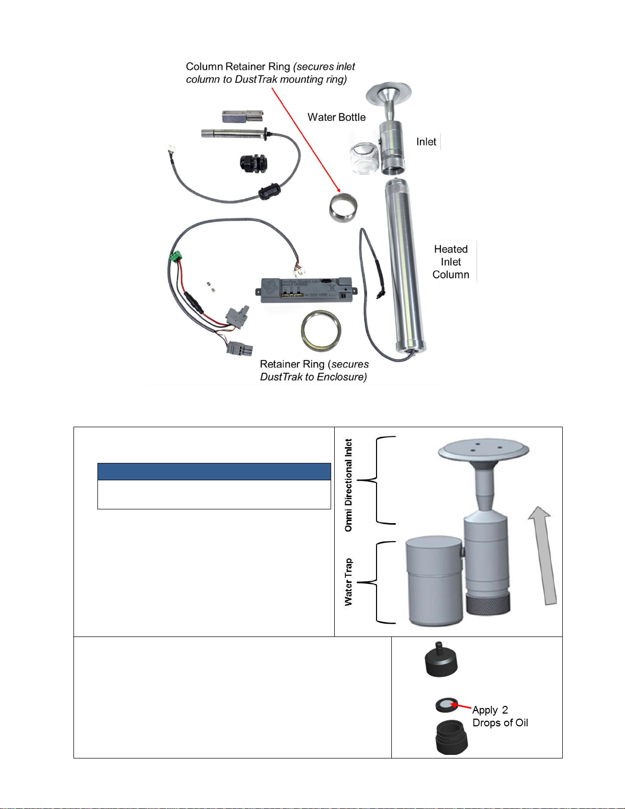
Assembly and Installation of Inlet Column
Installing the PM10 and PM2.5 Impactors (854020/854021)
1. Install the water trap bottle onto the side of the
Omni Directional Inlet as shown.
N O T E
For best results, use PTFE Thread Sealant
Tape on the water bottle threads.
2. Unscrew the PM2.5 or PM10 impactor to access the impactor
plate as it comes pre-assembled from the factory.
3. Apply two drops of oil (included) to the impactor plate. DO NOT
over-fill impactor plate.
4. Screw (hand-tighten) impactor back together.

–5–
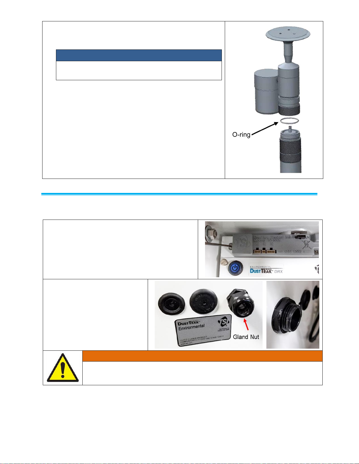
5. Install the Impactor onto the top of the Heated Inlet Sample
Conditioner column, by pushing it down.
6. Ensure the O-ring included with the Impactor Kit is installed
into the bottom of the Impactor housing.
7. Thread (hand-tighten) the impactor housing with O-ring onto
the heated inlet column.
Impactor
Housing
O-Ring
–6–
8. Attach the inlet to the top of the impactor housing. Ensure the
O-ring included with the inlet kit is installed into the bottom of
the inlet.
N O T E
Be sure to install column retainer ring onto heated inlet
column (refer to steps 9 and 10 for visual of retainer ring).
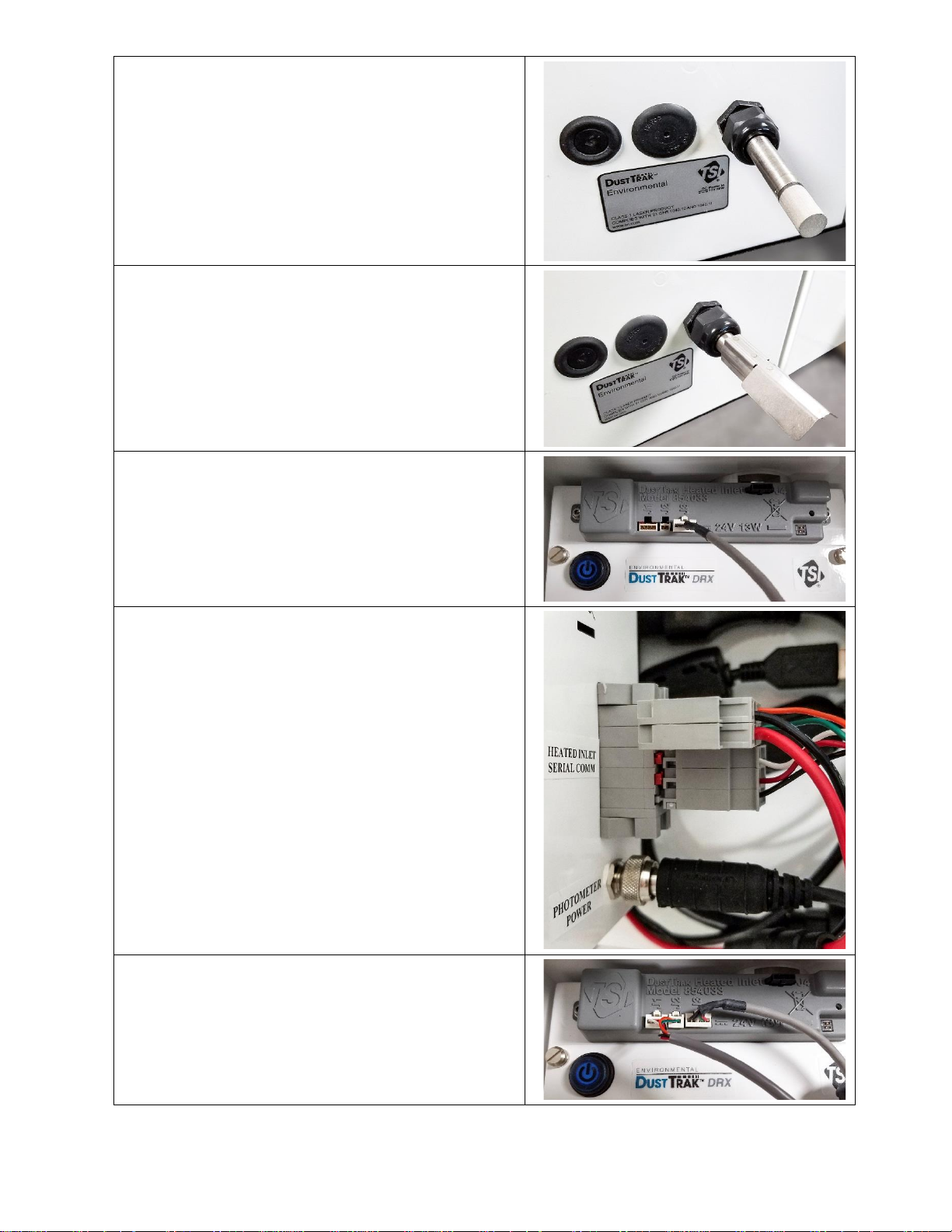
Installing Heated Inlet (854041) into Environmental Enclosure
1. Attach heated inlet control module to the front of
the Photometer. This can be done using the 2x
6-32 x 5/16 Socket Head Cap Screws and 2x flat
washers. Use a 7/64” ball driver.
2. Push out elastic plug and install
RH/Temp Sensor sealing gland.
Removable nut should be installed
on the inside of the enclosure.
W A R N I N G
Water gasket on gland must form a good seal with the exterior of the enclosure to ensure
a waterproof seal.
–7–
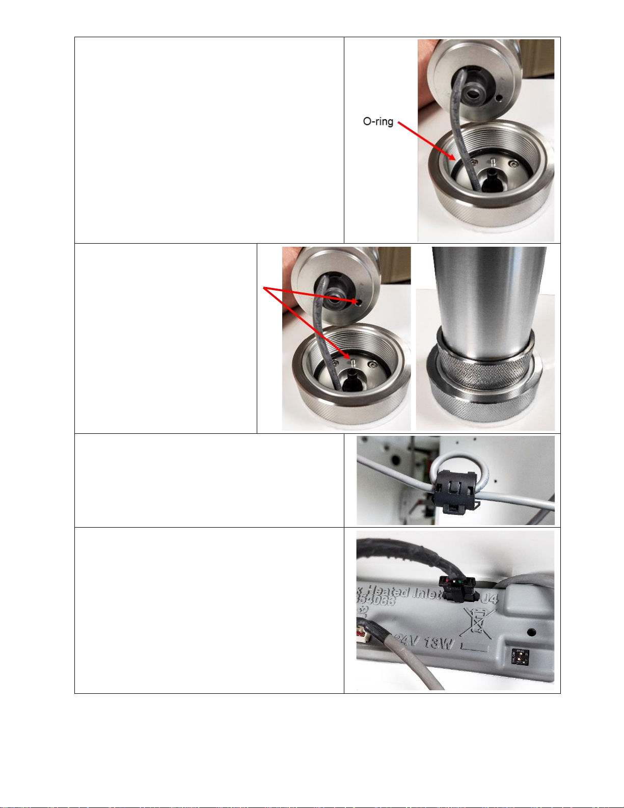
3. Insert RH/Temp Sensor through gland and tighten
gland nut. Extend probe ~2.75” (7 cm) beyond nut.
4. Attach the sun shield to the top of the RH/Temp
Sensor as shown. Sun Shield should not touch
sintered cap of RH/Temp Probe.
5. Attach RH/Temp Sensor cable to heated inlet
control module (J3).
6. Attach the two larger (gray) connectors to side of
the photometer.
7. Attach the two smaller (white) connectors to the
Power/Communication inputs (J1 and J2) of the
heated inlet control module (RH/Temp Sensor
Cable J3 is not shown for clarity).
–8–
8. Install O-ring and route cable through the mounting
ring. Pull excess cable through to prevent pinching
of cable when inlet column is installed.
9. Set inlet column on top of
photometer mounting ring, rotate
slowly until alignment pin mates
with the hole in the bottom of
heated inlet column.
10. Slide column retainer ring down
heated inlet column.
11. Hand-tighten column retainer ring
to secure inlet column to
photometer mounting ring.
12. Attach ferrite to cable with one wrap of the cable and
snap the ferrite together.
13. Attach heated inlet cable to heated inlet control
module (J4).

–9–
14. If using a Thiamis 1000 Node, route the other side of
the cable to the power input on the Thiamis node
(green connector).
Heated Inlet Operating Instructions
1. When powered and attached to the DustTrak™ monitor, the Heated Inlet will automatically function.
2. Select RH set point that will be controlled at the entrance to DustTrak™ monitor to be 30, 40 or 50%
RH via the DIP switches. Heated inlet will then power the heater to heat incoming air and thereby
decrease RH to the targeted level.
N O T E
By default, TSI® Incorporated (TSI®) sets the RH set point to 30% RH at the factory. If needed, this
can be adjusted to meet other application needs/requirements.
The LED describes the status of the heated inlet:
Solid Green
Inlet temp. is < 1°C below set point and controlling to maintain set point.
Blinking Green
Inlet temp. is between 1 to 5°C below set point and controlling to improve.
Blinking Red
Inlet temp. is more than 5°C below set point and controlling to improve. This will
occur when unit is first turned on and coming to temperature.
Solid Red
Sensor unplugged or has issue.

–10–
Heated Inlet Specifications
Power ......................................................
12-24 Volts DC; 13 Watts
Dimensions ............................................
Heated inlet
13 in. x 2 in. dia
(33 cm x 5 cm) dia
Control module
7 in. x 1.5 in. x 0.75 in.
(17.8 cm) x (3.8 cm) x (1.9 cm)
Temp Range ...........................................
0 to 50°C (32° to 122°F)
RH Range ...............................................
0 to 95%
RH Set Points.........................................
30% RH, 40%RH, 50% RH
Warm-up Time .......................................
17 minutes
CE ...........................................................
IEC 61326 & IEC 61010-1
Instrument Setup
Please refer to Model 8540-M, 8542-M, and 8543-M Operation and Service Manual (TSI® P/N 6008408)
for Set-Up Procedures.

–11–
(This page intentionally left blank)

_______________
TSI and TSI logo are registered trademarks of TSI Incorporated in the United States and may be protected under other country’s
trademark registrations.DustTrak is a trademark of TSI Incorporated.
TSI Incorporated – Visit our website www.tsi.com for more information.
USA Tel: +1 800 680 1220
UK Tel: +44 149 4 459200
France Tel: +33 1 41 19 21 99
Germany Tel: +49 241 523030
India Tel: +91 80 67877200
China Tel: +86 10 8219 7688
Singapore Tel: +65 6595 6388
P/N 6010298 Rev C ©2021 TSI Incorporated Printed in U.S.A.
 Loading...