

Page 1
Operator’s
Manual
TracStar® No.28
TracStar® No.412
TracStar® No.618
Fusion Machines
Patent No’s. 5,814,182 6,212,748 6,212,747 6,021,832
(other patents pending)
Manual: T1210801 Revision: C 7/04
Page 2

California
Proposition 65 Warning
Engine exhaust from this product
contains chemicals known to the State
of California to cause cancer, birth
defects, or other reproductive harm.
Page 3
Introduction
Thank you for purchasing this
McElroy product
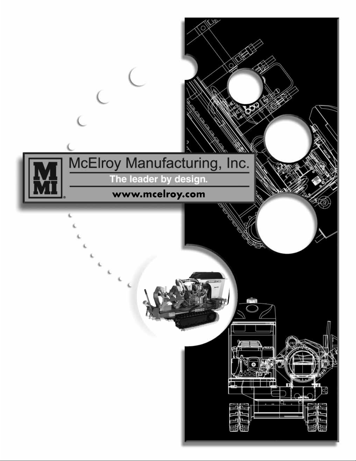
The McElroy TracStar
contained, self-propelled, all terrain fusion machine,
and is designed to produce consistently high quality
polyolefin pipe butt fusion joints with a minimum of
operator effort.
The TracStar® No.28 model fuses 2” IPS (63mm)
minimum to 8” DIPS (225mm) maximum pipe.
The TracStar® No.412 model fuses 4” IPS (110mm)
minimum to 12” DIPS (340mm) maximum pipe.
The TracStar® No.618 model fuses 6” IPS (180mm)
minimum to 18”IPS (450mm) maximum pipe.
With reasonable care and maintenance, this machine
will give years of exemplary service.
TX01853-9-27-00
®
No.28/No.412/No.618 self-
World Class Training
This manual is intended as a guide only and does not
take the place of proper training by qualified instructors.
The information in this manual is not all inclusive and
can not encompass all possible situations that can be
encountered during various operations.
Before operating this machine, please read this manual
thoroughly, and keep a copy with the machine for future
reference. This manual is to be considered part of your
machine.
Always return the manual to the literature compartment.
PH01894-9-27-00
Patent No’s. 5,814,182 6,212,748 6,212,747 6,021,832
(other patents pending)
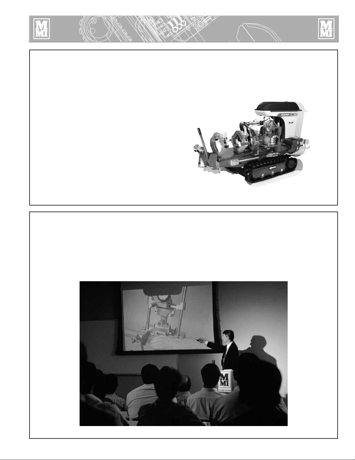
McElroy Manufacturing, Inc., offers advanced training
classes to enhance efficiency, productivity, safety and
quality. Training is available at our facility or on-site at
your location. Call (918) 836-8611.
TX01315-4-7-97
8-15-97
PH00917-
Page 4

Warranty
LIMITED WARRANTY
McElroy Manufacturing, Inc. guarantees this product to
the original purchaser against workmanship and material
defects for three (3) years from date of shipment, with the
exception of purchased items (such as electronic devices,
pumps, switches, etc.), in which case that manufacturer's
warranty applies. This warranty does not apply to any
product or component which has been repaired or
altered by anyone other than McElroy Manufacturing,
Inc., or has become damaged due to misuse, negligence
or casualty, or has not been operated or maintained
according to McElroy Manufacturing, Inc.'s printed
instructions and warnings.
Claims cannot be allowed until the questioned product
has been received, freight prepaid, at the manufacturer's
factory, with complete information and data regarding
the failure. Materials returned to McElroy Manufacturing,
Inc. for warranty work, repair, etc., must have a Return
Material Authorization (RMA) number, and be so noted
on the package at time of shipment. This number may be
obtained by calling (918) 836-8611. If seller's review
indicates that warranty applies, the defective product
will be repaired or replaced and returned to purchaser
F.O.B. Tulsa, Oklahoma.
McElroy Manufacturing, Inc. is not responsible or
liable for loss of any sort including incidental and
consequential damages.
McElroy Manufacturing, Inc. specifically disavows any
other representations as to warranty or liability, related to
the condition or use of the product.
For assistance, inquiries shall be directed to McElroy
Manufacturing, Inc., P.O. Box 580550, 833 North
Fulton, Tulsa, Oklahoma 74158-0550, (918) 836-8611,
Fax No. (918) 831-9285, www.mcelroy.com
Register Your Warranty Online:
www.mcelroy.com
DISCLAIMER OF LIABILITY
McElroy Manufacturing, Inc. accepts no responsibility of
liability for fusion joints. Operation and maintenance of
the product is the responsibility of others. We recommend
qualified joining procedures be followed when using
McElroy fusion equipment.
McELROY MAKES NO OTHER WARRANTY OF ANY
KIND WHATEVER, EXPRESS OR IMPLIED; AND ALL
IMPLIED WARRANTIES OF MERCHANTABILITY AND
FITNESS FOR A PARTICULAR PURPOSE WHICH
EXCEED THE AFORESTATED OBLIGATION ARE HEREBY
DISCLAIMED BY McELROY.
PRODUCT IMPROVEMENT
McElroy Manufacturing, Inc. reserves the right to make
any changes in or improvements on its products without
incurring any liability or obligation to update or change
previously sold machines and/or the accessories thereto.
TERMS AND CONDITIONS
Net 30 Days - Subject to credit approval. A carrying
charge of 1-1/2% per month computed from invoice
date will apply to invoices not paid within 30 Day Terms.
McElroy Manufacturing, Inc. must be notified of any
discrepancy in shipment, order, and/or invoice within 10
days after receipt.
Freight is F.O.B. Tulsa, Oklahoma - usually motor freight
collect or UPS unless otherwise specified.
Prices are subject to change without notice.
Minimum order is $50.00.
(Copy information listed on the Warranty Card for your
records).
Model No. ________________________________________
Serial No. ________________________________________
Date Received _____________________________________
Distributor _________________________________________
TX01901-11-15-00
Page 5

Equipment Safety
Safety Alerts . . . . . . . . . . . . . . . . . . . . . . . . . . . . . . . . . . . . . . . . . . 1-1
Read and Understand . . . . . . . . . . . . . . . . . . . . . . . . . . . . . . . . . . . 1-1
General Safety . . . . . . . . . . . . . . . . . . . . . . . . . . . . . . . . . . . . . . . . 1-2
Wear Safety Equipment . . . . . . . . . . . . . . . . . . . . . . . . . . . . . . . . . . 1-2
Fuel Handling . . . . . . . . . . . . . . . . . . . . . . . . . . . . . . . . . . . . . . . . . 1-2
Units with Engines . . . . . . . . . . . . . . . . . . . . . . . . . . . . . . . . . . . . . . 1-3
Carbon Monoxide . . . . . . . . . . . . . . . . . . . . . . . . . . . . . . . . . . . . . . 1-3
Heater is Not Explosion Proof . . . . . . . . . . . . . . . . . . . . . . . . . . . . . . 1-3
Electric Motors and Alternators are Not Explosion Proof . . . . . . . . . . . . 1-3
Battery . . . . . . . . . . . . . . . . . . . . . . . . . . . . . . . . . . . . . . . . . . . . . . 1-4
Electrical Safety . . . . . . . . . . . . . . . . . . . . . . . . . . . . . . . . . . . . . . . . 1-4
Crush Points . . . . . . . . . . . . . . . . . . . . . . . . . . . . . . . . . . . . . . . . . . 1-5
Facer Blades are Sharp . . . . . . . . . . . . . . . . . . . . . . . . . . . . . . . . . . 1-5
Units with Hydraulics . . . . . . . . . . . . . . . . . . . . . . . . . . . . . . . . . . . . 1-5
Keep Machine Away from Edge of Ditch . . . . . . . . . . . . . . . . . . . . . . 1-6
Operating Fusion Machine . . . . . . . . . . . . . . . . . . . . . . . . . . . . . . . . 1-6
Do Not Attempt to Tow Fusion Machine . . . . . . . . . . . . . . . . . . . . . . . 1-6
Heater is Hot . . . . . . . . . . . . . . . . . . . . . . . . . . . . . . . . . . . . . . . . . . 1-6
Fusion Procedures . . . . . . . . . . . . . . . . . . . . . . . . . . . . . . . . . . . . . . 1-7
Periodically Check Temperature . . . . . . . . . . . . . . . . . . . . . . . . . . . . . 1-7
Hearing Protection Required . . . . . . . . . . . . . . . . . . . . . . . . . . . . . . . 1-7
Positioning Fusion Machine . . . . . . . . . . . . . . . . . . . . . . . . . . . . . . . 1-7
Table of Contents
Overview
Theory of Heat Fusion . . . . . . . . . . . . . . . . . . . . . . . . . . . . . . . . . . . 2-1
Carriage Assembly . . . . . . . . . . . . . . . . . . . . . . . . . . . . . . . . . . . . . 2-2
Chassis . . . . . . . . . . . . . . . . . . . . . . . . . . . . . . . . . . . . . . . . . . . . . . 2-2
Gas Powered Units . . . . . . . . . . . . . . . . . . . . . . . . . . . . . . . . . . . . . 2-3
Tach and Hour Meter for Gas Unit . . . . . . . . . . . . . . . . . . . . . . . . . . . 2-3
Diesel Powered Units . . . . . . . . . . . . . . . . . . . . . . . . . . . . . . . . . . . . 2-3
Diesel & Gas Engine Controls . . . . . . . . . . . . . . . . . . . . . . . . . . . . . . 2-4
Power for Heater . . . . . . . . . . . . . . . . . . . . . . . . . . . . . . . . . . . . . . . 2-4
Oil Reservoir . . . . . . . . . . . . . . . . . . . . . . . . . . . . . . . . . . . . . . . . . . 2-4
Hydraulic Oil Filter . . . . . . . . . . . . . . . . . . . . . . . . . . . . . . . . . . . . . 2-4
Hydraulic Manifold Block . . . . . . . . . . . . . . . . . . . . . . . . . . . . . . . . . 2-5
Hydraulic Cylinders . . . . . . . . . . . . . . . . . . . . . . . . . . . . . . . . . . . . . 2-5
Facer . . . . . . . . . . . . . . . . . . . . . . . . . . . . . . . . . . . . . . . . . . . . . . . 2-6
Insulated Heater Stand . . . . . . . . . . . . . . . . . . . . . . . . . . . . . . . . . . . 2-6
Heater . . . . . . . . . . . . . . . . . . . . . . . . . . . . . . . . . . . . . . . . . . . . . . 2-7
COPYRIGHT © 2004
McELROY MANUFACTURING, INC.
Tulsa, Oklahoma, USA
All rights reserved
All product names or trademarks are property of their respective owners. All information,
illustrations and specifications in this manual are based on the latest information available
at the time of publication. The right is reserved to make changes at any time without notice.
Page 6

Operation
Table of Contents
Read Before Operating . . . . . . . . . . . . . . . . . . . . . . . . . . . . . . . . . . 3-1
Check Oil Level . . . . . . . . . . . . . . . . . . . . . . . . . . . . . . . . . . . . . . . . 3-1
Diesel Engine . . . . . . . . . . . . . . . . . . . . . . . . . . . . . . . . . . . . . . . . . 3-1
Gas Powered Units . . . . . . . . . . . . . . . . . . . . . . . . . . . . . . . . . . . . . 3-1
Moving Machine into Position . . . . . . . . . . . . . . . . . . . . . . . . . . . . . . 3-2
Prepare Heater . . . . . . . . . . . . . . . . . . . . . . . . . . . . . . . . . . . . . . . . 3-2
Set up Pipe Supports . . . . . . . . . . . . . . . . . . . . . . . . . . . . . . . . . . . . 3-2
Install Clamping Inserts . . . . . . . . . . . . . . . . . . . . . . . . . . . . . . . . . . . 3-3
Check Hydraulic Pressure . . . . . . . . . . . . . . . . . . . . . . . . . . . . . . . . . 3-3
Loading Pipe Into Machine . . . . . . . . . . . . . . . . . . . . . . . . . . . . . . . . 3-4
Positioning Pipe in Machine . . . . . . . . . . . . . . . . . . . . . . . . . . . . . . . 3-4
Facing the Pipe . . . . . . . . . . . . . . . . . . . . . . . . . . . . . . . . . . . . . . . . 3-4
Remove Facer . . . . . . . . . . . . . . . . . . . . . . . . . . . . . . . . . . . . . . . . . 3-5
Position Carriage for Heater Insertion . . . . . . . . . . . . . . . . . . . . . . . . 3-6
Check Heater Temperature . . . . . . . . . . . . . . . . . . . . . . . . . . . . . . . . 3-6
Select the Fusion Position . . . . . . . . . . . . . . . . . . . . . . . . . . . . . . . . . 3-6
Inserting Heater . . . . . . . . . . . . . . . . . . . . . . . . . . . . . . . . . . . . . . . . 3-7
Heating the Pipe . . . . . . . . . . . . . . . . . . . . . . . . . . . . . . . . . . . . . . . 3-7
Fusing the Pipe . . . . . . . . . . . . . . . . . . . . . . . . . . . . . . . . . . . . . . . . 3-8
Opening Movable Jaws . . . . . . . . . . . . . . . . . . . . . . . . . . . . . . . . . . 3-8
Opening Fixed Jaws . . . . . . . . . . . . . . . . . . . . . . . . . . . . . . . . . . . . 3-9
Raise Pipe . . . . . . . . . . . . . . . . . . . . . . . . . . . . . . . . . . . . . . . . . . . . 3-9
Hydraulic Pipelifts . . . . . . . . . . . . . . . . . . . . . . . . . . . . . . . . . . . . . . 3-9
Position Pipe for Next Joint . . . . . . . . . . . . . . . . . . . . . . . . . . . . . . . . 3-10
Install Next Piece of Pipe . . . . . . . . . . . . . . . . . . . . . . . . . . . . . . . . . 3-10
Special Operations - In Ditch
Disconnect Hydraulic Hoses . . . . . . . . . . . . . . . . . . . . . . . . . . . . . . . 4-1
Remove Carriage Assembly from the Chassis . . . . . . . . . . . . . . . . . . . 4-1
Remove 3-Jaw Assembly from the Carriage . . . . . . . . . . . . . . . . . . . . 4-2
Remove Facer from TracStar No.412 & No.618 . . . . . . . . . . . . . . . . . 4-3
Remove Facer from TracStar No.28 . . . . . . . . . . . . . . . . . . . . . . . . . 4-4
Manual Facer Operation . . . . . . . . . . . . . . . . . . . . . . . . . . . . . . . . . 4-5
Removing Top Jaws . . . . . . . . . . . . . . . . . . . . . . . . . . . . . . . . . . . . . 4-6
Lower 3-Jaw or 4-Jaw Carriage into Ditch . . . . . . . . . . . . . . . . . . . . . 4-6
Clamp Carriage Assembly to Pipe . . . . . . . . . . . . . . . . . . . . . . . . . . . 4-7
Attach Hydraulic Hoses . . . . . . . . . . . . . . . . . . . . . . . . . . . . . . . . . . 4-8
Make Fusion Joint . . . . . . . . . . . . . . . . . . . . . . . . . . . . . . . . . . . . . . 4-8
Remove Carriage Assembly from Ditch . . . . . . . . . . . . . . . . . . . . . . . . 4-8
Reassemble Fusion Machine . . . . . . . . . . . . . . . . . . . . . . . . . . . . . . . 4-8
Special Operations - Saddle Fusion Procedures
Saddle Fusion Procedure for TracStar No.28 . . . . . . . . . . . . . . . . . . . 5-1
Install Heater Adapters . . . . . . . . . . . . . . . . . . . . . . . . . . . . . . . . . . . 5-1
Assure Saddle will Fit . . . . . . . . . . . . . . . . . . . . . . . . . . . . . . . . . . . . 5-1
Install Clamping Inserts . . . . . . . . . . . . . . . . . . . . . . . . . . . . . . . . . . . 5-2
Remove Carriage Assembly from Vehicle . . . . . . . . . . . . . . . . . . . . . . 5-2
Attach Carriage Assembly to Main . . . . . . . . . . . . . . . . . . . . . . . . . . 5-2
Set Hydraulic Pressure . . . . . . . . . . . . . . . . . . . . . . . . . . . . . . . . . . . 5-2
Clean Surfaces . . . . . . . . . . . . . . . . . . . . . . . . . . . . . . . . . . . . . . . . 5-3
Page 7

Table of Contents
Special Operations - Saddle Fusion Procedures - Continued
Clamp Fitting . . . . . . . . . . . . . . . . . . . . . . . . . . . . . . . . . . . . . . . . . 5-3
Test for Slippage . . . . . . . . . . . . . . . . . . . . . . . . . . . . . . . . . . . . . . . 5-3
Prepare Heater . . . . . . . . . . . . . . . . . . . . . . . . . . . . . . . . . . . . . . . . 5-4
Heat Pipe and Fitting . . . . . . . . . . . . . . . . . . . . . . . . . . . . . . . . . . . . 5-4
Remove Heater . . . . . . . . . . . . . . . . . . . . . . . . . . . . . . . . . . . . . . . . 5-4
Fuse Fitting to Pipe . . . . . . . . . . . . . . . . . . . . . . . . . . . . . . . . . . . . . . 5-5
Allow Joint to Cool . . . . . . . . . . . . . . . . . . . . . . . . . . . . . . . . . . . . . 5-5
Special Operations - Lifting the Machine
Heavy Overhead Load . . . . . . . . . . . . . . . . . . . . . . . . . . . . . . . . . . . 6-1
Crush Points . . . . . . . . . . . . . . . . . . . . . . . . . . . . . . . . . . . . . . . . . . 6-1
Required Equipment . . . . . . . . . . . . . . . . . . . . . . . . . . . . . . . . . . . . . 6-1
Attach Slings . . . . . . . . . . . . . . . . . . . . . . . . . . . . . . . . . . . . . . . . . . 6-2
Lifting Safety . . . . . . . . . . . . . . . . . . . . . . . . . . . . . . . . . . . . . . . . . . 6-2
Maintenance
Preventative Maintenance . . . . . . . . . . . . . . . . . . . . . . . . . . . . . . . . . 7-1
Washing the Machine . . . . . . . . . . . . . . . . . . . . . . . . . . . . . . . . . . . 7-1
Check Hydraulic Fluid . . . . . . . . . . . . . . . . . . . . . . . . . . . . . . . . . . . 7-1
Change Hydraulic Fluid and Filter . . . . . . . . . . . . . . . . . . . . . . . . . . . 7-1
Install/Remove Covers . . . . . . . . . . . . . . . . . . . . . . . . . . . . . . . . . . . 7-2
Engine Belt Tension Adjustment . . . . . . . . . . . . . . . . . . . . . . . . . . . . . 7-3
Tensioning the Belt . . . . . . . . . . . . . . . . . . . . . . . . . . . . . . . . . . . . . . 7-3
Adjusting System Pressure . . . . . . . . . . . . . . . . . . . . . . . . . . . . . . . . . 7-3
Engine Oil System - Diesel . . . . . . . . . . . . . . . . . . . . . . . . . . . . . . . . 7-4
Engine Oil System - Gasoline . . . . . . . . . . . . . . . . . . . . . . . . . . . . . . 7-4
Check Gauge Calibration . . . . . . . . . . . . . . . . . . . . . . . . . . . . . . . . . 7-5
Clean Jaws and Inserts . . . . . . . . . . . . . . . . . . . . . . . . . . . . . . . . . . . 7-5
Clean Thrust Bearings . . . . . . . . . . . . . . . . . . . . . . . . . . . . . . . . . . . 7-5
Clean Eyebolt Threads . . . . . . . . . . . . . . . . . . . . . . . . . . . . . . . . . . . 7-5
Clean the Clamping Chains . . . . . . . . . . . . . . . . . . . . . . . . . . . . . . . 7-6
Fasteners Must Be Tight . . . . . . . . . . . . . . . . . . . . . . . . . . . . . . . . . . 7-6
Facer Blades . . . . . . . . . . . . . . . . . . . . . . . . . . . . . . . . . . . . . . . . . . 7-6
Check/Add Antifreeze . . . . . . . . . . . . . . . . . . . . . . . . . . . . . . . . . . . 7-6
Clean Heater Surfaces . . . . . . . . . . . . . . . . . . . . . . . . . . . . . . . . . . . 7-7
Bleeding Air From Hydraulic System . . . . . . . . . . . . . . . . . . . . . . . . . 7-7
Installing Butt Fusion Heater Adapter . . . . . . . . . . . . . . . . . . . . . . . . . 7-8
Adjusting Heater Temperature . . . . . . . . . . . . . . . . . . . . . . . . . . . . . . 7-8
Indicator Light . . . . . . . . . . . . . . . . . . . . . . . . . . . . . . . . . . . . . . . . . 7-8
Engine Maintenance . . . . . . . . . . . . . . . . . . . . . . . . . . . . . . . . . . . . 7-9
Checking Track Tension . . . . . . . . . . . . . . . . . . . . . . . . . . . . . . . . . . 7-9
Adjusting Track Tension . . . . . . . . . . . . . . . . . . . . . . . . . . . . . . . . . . 7-10
Setting Engine Speed . . . . . . . . . . . . . . . . . . . . . . . . . . . . . . . . . . . . 7-10
Machine Maintenance Checklist
Machine Checklist . . . . . . . . . . . . . . . . . . . . . . . . . . . . . . . . . . . . . . 8-1
Determining Fusion Pressure
Determining Fusion Pressure . . . . . . . . . . . . . . . . . . . . . . . . . . . . . . . 9-1
Hydraulic Fluid
Hydraulic Fluid Characteristics . . . . . . . . . . . . . . . . . . . . . . . . . . . . . 10-1
Specifications
TracStar® No.28 & No.412 Fusion Machine Specifications . . . . . . . . . 11-1
TX02032-7-8-02
TracStar® No.618Fusion Machine Specifications . . . . . . . . . . . . . . . . 11-2
Page 8

Safety Alerts
Fusion Equipment Safety
This hazard alert sign appears in this manual.
When you see this sign, carefully read what it says.
YOUR SAFETY IS AT STAKE.
You will see the hazard alert sign with these words:
DANGER, WARNING, and CAUTION.
Indicates an imminently hazardous
situation which, if not avoided, will
result in death or serious injury.
Indicates a potentially hazardous
situation which, if not avoided, could
result in death or serious injury.
Indicates a hazardous situation which,
if not avoided, may result in minor or
moderate injury.
In this manual you should look for two other words:
NOTICE and IMPORTANT.
NOTICE: can keep you from doing something that might
damage the machine or someone's property. It may also
be used to alert against unsafe practices.
IMPORTANT: can help you do a better job or make
your job easier in some way.
-11-30-92
WR00051
TX00030-12-1-92
Read and Understand
Do not operate this equipment until you have carefully read, and
understand the "Safety" and "Operation" sections of this manual,
and all other equipment manuals that will be used with it.
Your safety and the safety of others depends upon care and
judgment in the operation of this equipment.
Follow all applicable federal, state, local, and industry specific
regulations.
McElroy Manufacturing, Inc. cannot anticipate every possible
circumstance that might involve a potential hazard. The warnings
in this manual and on the machine are therefore not all inclusive.
You must satisfy yourself that a procedure, tool, work method, or
operating technique is safe for you and others. You should also
ensure that the machine will not be damaged or made unsafe by
the method of operation or maintenance you choose.
TX00031-12-8-92
WR00052-12-1-92
1 - 1
Page 9
Fusion Equipment Safety
General Safety
Safety is important. Report anything unusual that you notice
during set up or operation.
LISTEN for thumps, bumps, rattles, squeals, air leaks, or unusual
sounds.
SMELL odors like burning insulation, hot metal, burning rubber,
hot oil, or natural gas.
FEEL any changes in the way the equipment operates.
SEE problems with wiring and cables, hydraulic connections, or
other equipment.
REPORT anything you see, feel, smell, or hear that is different from
what you expect, or that you think may be unsafe.
TX00114-4-22-93
T-12-22-92
S
SAFE1
Wear Safety Equipment
Wear a hard hat, safety shoes, safety glasses, and other
applicable personal protective equipment.
Remove jewelry and rings, and do not wear loose-fitting clothing
or long hair that could catch on controls or moving machinery.
TX00032-4-7-93
Fuel Handling
Gasoline and diesel fuel are extremely flammable
and their vapors will explode if ignited.
Do not fill the fuel tank while the engine is hot or running, as
spilled fuel could ignite.
Refuel in a well ventilated area. Do not smoke or allow flames
or sparks in the area where the engine is refueled, or where
gasoline is stored.
Do not start the engine near spilled fuel. Wipe up spills
immediately.
Maker sure the fuel tank cap is closed and properly secured.
Avoid repeated or prolonged contact with skin or breathing of
vapor.
WR00053-12-2-92
-2-19-97
CD00365
FUEL
TX00953-2-19-97
1 - 2
Page 10

Fusion Equipment Safety
Units With Engines
Combustion engines can cause explosions when
operated in a hazardous environment. Do not
operate gas or diesel powered machines in a
hazardous environment.
When operating in a hazardous environment, keep engine and
chassis in a safe area by using hydraulic extension hoses.
Help prevent fires by keeping machine clean of accumulated
trash, debris and facer shavings.
TX01266-2-21-97
Carbon Monoxide
Engine exhaust gases contain carbon monoxide
which can cause severe nausea, fainting and
death. Avoid inhaling exhaust fumes and never
run the engine in a closed or confined area.
WR00080-4-12-93
WR00093-5-14-96
TX00954-5-14-96
Heater Is Not Explosion Proof
The heater is not explosion proof. Operation
of heater is a hazardous environment without
necessary safety precautions will result in
explosion and death.
If operating in a hazardous environment, the heater should be
brought up to temperature in a safe environment, then unplugged
before entering the hazardous atmosphere for fusion.
TX00100-9-16-94
Electric Motors and Alternators are Not
Explosion Proof
Electric motors are not explosion proof. Operation
of these components in a hazardous environment
without necessary safety precautions will result in
explosion and death.
When operating in a hazardous environment, keep pump motor
and chassis in a safe area by using hydraulic extension hoses.
WR00034-11-30-92
WR00080-4-12-93
TX00424-8-12-94
1 - 3
Page 11
Battery
Fusion Equipment Safety
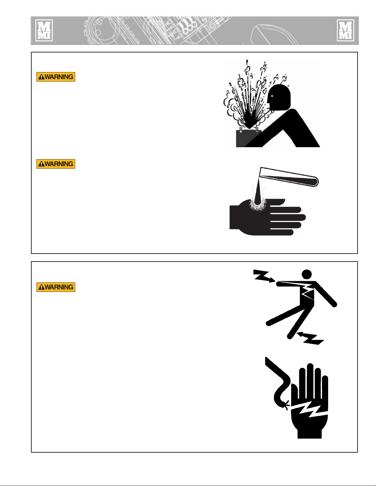
Do not expose the battery to flames or electrical
sparks. Hydrogen gas generated by battery action
is explosive. Blindness or serious injury can result
from an exploding battery.
Do not allow battery fluid to contact your skin, eyes,
fabrics, or painted surfaces. Sulfuric acid can cause
burns. After touching a batter or battery cap, do not
touch or rub your eyes.
Thoroughly wash your hands. If the acid contacts
your eyes, skin or clothing, immediately flush with
water for at least 15 minutes and seek medical
attention.
CD00176-9-14-95
CD00177-9-14-95
TX00650-9-14-95
Electrical Safety
Always ensure power cords are properly
grounded. It is important to remember that you
are working in a wet environment with electrical
devices. Proper ground connections help to
minimize the chances of an electric shock.
Frequently inspect electrical cords and unit for damage. Have
damaged components replaced and service performed by a
qualified electrician.
Do not carry electrical devices by the cord.
NOTICE: Always connect units to the proper power source as
listed on the unit, or in the owner's manual. On units with two
power cords, plug each cord into separate power circuits. Do not
plug into both outlets of one duplex receptacle.
NOTICE: Disconnect the machine from the power source before
attempting any maintenance or adjustment.
WR00055-4-7-93
WR00025-11-30-92
TX00105-4-12-93
1 - 4
Page 12
Fusion Equipment Safety
Crush Points
Hydraulically operated jaws are operated under
pressure. Anything caught in the jaws will be
crushed. Keep fingers, feet, arms, legs, and
head out of the jaw area. Always check pipe
alignment with a pencil or similar object.
TX00103-4-6-93
Facer Blades Are Sharp
Facer blades are sharp and can cut. Never
attempt to remove shavings while the facer is
running, or is in the facing position between the
jaws. Use care when operating the facer, and
when handling the unit.
NOTICE: Disconnect power from the facer, and remove the facer
blades before attempting any maintenance or adjustment.
WR00012-12-4-92
WR00073-4-6-93
TX00102-4-16-93
Units With Hydraulics
Although the hydraulic pressures in this machine are low
compared to some hydraulically operated equipment, it is
important to remember that a sudden hydraulic oil leak can cause
serious injury, or even be fatal if the pressure is high enough.
Escaping fluid under pressure can penetrate the
skin causing serious injury. Keep hands and
body away from pinholes which eject fluid under
pressure. Use a piece of cardboard or paper to
search for leaks. If any fluid is injected into the
skin, it must be immediately removed by a doctor
familiar with this type of injury.
NOTICE: Wear safety glasses, and keep face clear of area when
bleeding air from hydraulic system to avoid spraying oil into eyes.
WR00078-4-8-93
TX00110-8-23-95
1 - 5
Page 13

Fusion Equipment Safety
0
100
200
300
400
500
600
700
800
900
1000
DIRECTIONAL
CONTROL
VALVE
FACING
PRESSURE
HEATING
PRESSURE
FUSING
PRESSURE
SELECTOR
VALVE
0
10
0
20
0
300
40
0
5
0
0
600
70
0
800
900
1
0
0
0
DIRECTIONAL
CONTROL
VALVE
FACING
PRESSURE
HEATING
PRESSURE
FUSING
PRESSURE
SELECTOR
VALVE
Keep Machine Away From Edge of Ditch
Heavy equipment too close to a ditch can
cause the walls of the ditch to cave-in. Keep
the machine far enough away from the edge
of the ditch to prevent injury to personnel and
equipment from a cave-in.
TX01447-12-30-97
Operating Fusion Machine
Place fusion machine on as level ground as possible.
If it is necessary to operate machine on unlevel grade, make
sure that the ground is stable. Some unstable conditions may be
ice, snow, mud and loose gravel.
For operation safety, never operate the machine
on a grade steeper than 30 %. (A 3 foot
elevation change in 10 feet)
CD00408b-9-27-00
CD00402c-9-27-00
3
TX011902-11-15-00
Do Not Attempt to Tow Fusion Machine
The machine is not designed for towing.
Attempting to tow the machine can result in
machine damage. Always transport the machine
by flat bed truck or similar means, and make sure
that unit is properly secured.
TX01888-11-15-00
Heater is Hot
The heater is hot and will burn clothing and skin.
Keep the heater in its insulated heater stand or
blanket when not in use, and use care when
heating the pipe.
NOTICE: Use only a clean non-synthetic cloth such as a cotton
cloth to clean the heater plates.
TX00104-8-12-94
10
CD00401b-9-27-00
WR00030-2-10-93
1 - 6
Page 14
Fusion Equipment Safety
Fusion Procedures
Obtain a copy of the pipe manufacturer's procedures for the pipe
being fused. Follow the procedure carefully, and adhere to all
specified parameters.
Failure to follow pipe manufacturer's procedure
could result in a bad joint. Always follow pipe
manufacturer's procedures.
TX00113-4-12-93
Periodically Check Temperature
NOTICE: Incorrect heating temperature can result in bad fusion
joints. Check heater plate surface temperature periodically with a
properly calibrated pyrometer, and make necessary adjustments.
The thermometer on heaters indicates internal temperature, and
should be used as a reference only.
WR00079-1-24-96
WR00077-4-16-93
TX00107-11-13-95
Positioning Fusion Machine
Place fusion machine on as level ground as possible. If it is necessary to
operate machine on unlevel grade, chock the tracks and block the unit to
make it as stable as possible.
TX01889-11-15-00
Hearing Protection Required
When operating machine for more than 4 hours per day wear
hearing protection.
CD00633-9-27-00
WR00028-1-24-96
TX01890-11-15-00
1 - 7
Page 15
Overview
Theory of Heat Fusion
The principle of heat fusion is to heat two surfaces to a
designated temperature, and then fuse them together by
application of force. This pressure causes flow of the melted
materials, which causes mixing and thus fusion. When the
polyethylene material is heated, the molecular structure is
transformed from a crystalline state into an amorphous condition.
When fusion pressure is applied, the molecules from each
Polyethylene part mix. As the joint cools, the molecules return to
their crystalline form, the original interfaces are gone, and the
fitting and pipe have become one homogeneous unit. The joint
area becomes as strong as the pipe itself in both tensile and
pressure conditions.
The principle operations include:
Clamping The pipe pieces held axially to allow all subsequent
operations to take place.
Facing The pipe ends must be faced to establish clean,
parallel mating surfaces perpendicular to the
centerline of the pipes.
Alignment The pipe ends must be aligned with each other to
minimize mismatch or high-low of the pipe walls.
Heating A melt pattern that penetrates into the pipe must be
formed around both pipe ends.
Joining The melt patterns must be joined with a specified
force. The force must be constant around the interface
area.
Holding The molten joint must be held immobile with a
specified force until adequately cooled.
PH00363B-1-4-96
Each pipe manufacturer has a slightly different approach for
fulfilling the heating, joining, and holding phases, but the end
result is the same -- a fusion joint that is as strong or stronger than
the pipe itself.
TX00441-9-22-94
2 - 1
Page 16
Overview
Carriage Assembly
The carriage assembly consists of two fixed jaws and two
hydraulically operated movable jaws bolted to the skid. For
remote operation the carriage can be set in ditch and connected
to the machine with optional hydraulic extension hoses.The
carriage assembly (A) can be disconnected from the chassis (B)
and removed for remote operation. The optional extension hose
kit is required for this operation.
For tight installations the outer fixed jaw and skid can be removed
from the carriage for an even more compact fusion unit.
A
PH01940-11-15-00
TX01891-11-15-00
Chassis
The carriage assembly is mounted on a track driven chassis for
easy loading and movement along the pipe line.
The engine powers an alternator, used to power the heater, and a
hydraulic pump, which powers the fusion machine and the track
drive. A belt drive is used to transfer the power. The hydraulic
reservoir is mounted above the engine. The fuel tank and battery
are installed between the tracks.
B
PH01953-11-15-00
PH01966-11-15-00
TX01854-11-15-00
PH01959-11-15-00
2 - 2
Page 17
Overview
Gas Powered Units
Read the operating and maintenance instructions for the engine
before operating.
The engine is a single cylinder, overhead valve, air cooled
design. It uses a vacuum operated fuel pump.
The fuel shutoff valve is located by the carburetor.
PH01965-11-15-00
PH02243-1-10-02
TX01987-1-10-02
Tach and Hour Meter for Gas Unit
When the unit is running, the engine speed is displayed. When
the unit is not running, total hours of engine operation are
displayed.
On diesel powered units an hour meter is provided in the same
location.
TX01892-11-15-00
Diesel Powered Units
Read the operating and maintenance instructions for the engine
before operating.
The engine is a twin cylinder water cooled design. It uses an
electric fuel pump located near the fuel tank.
PH01988-11-15-00
PH01960-11-15-00
TX01855-11-15-00
2 - 3
Page 18
Overview
Diesel Engine Controls
Read the operating and maintenance instructions for the engine
before operating.
There is a key ignition on the console that shows the preheat off,
run, and start positions.
Gas Engine Controls
Choke and throttle control is on the dash.
There is a key ignition on the console that shows the off, run, and
start positions.
TX01986-1-10-02
Power for Heater
The heater cord plugs into a receptacle on the frame.
The 110V receptacle is used for the No.28 Butt Fusion Heater.
The 220V receptacle is used for the No.412 Butt Fusion Heater
and the No.28 Sidewall Heaters.
PH01969-11-15-00
PH01922-11-15-00
TX01856-9-28-00
Oil Reservoir
The oil reservoir is located above the engine.
TX02306-7-28-04
Hydraulic Oil Filter
This machine is equipped with a 10 Micron filter on the return
side of the hydraulic system.
PH02709-07-29-04
PH01916-11-15-00
TX01893-11-15-00
2 - 4
Page 19
Overview
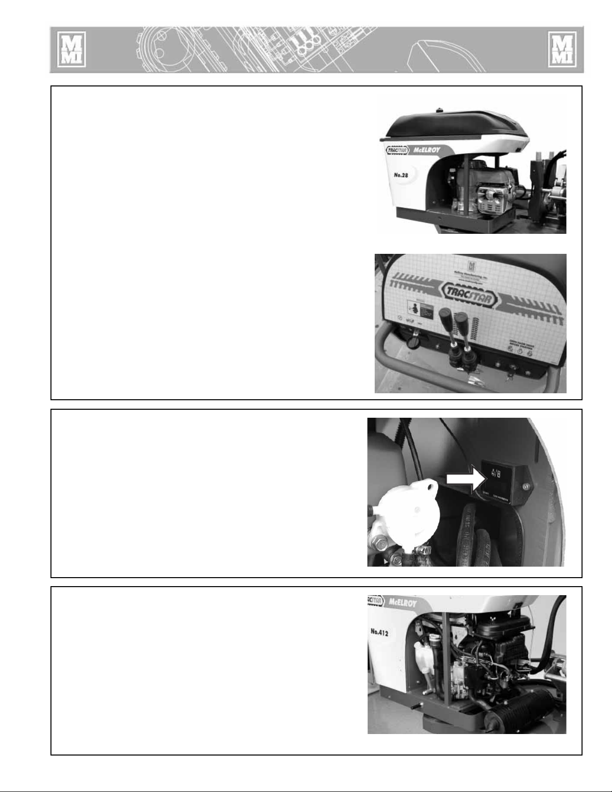
Hydraulic Manifold Block
Mounted on this block are a carriage directional control valve, a
pressure reducing selector valve, three pressure reducing valves,
and a 1500 psi gauge.
A) The carriage control valve, mounted on the top of the
manifold, determines whether the carriage is moving left,
right, or is in neutral.
B) A 1500 psi gauge is mounted on top of the manifold.
C) The selector valve, mounted on the front of the manifold,
selects a reduced pressure from one of the pressure reducing
valves.
Each pressure reducing valve is labeled with a different function:
D) The top valve adjusts facing pressure to a maximum of 400
psi.
E) The middle valve adjusts heating pressure to a maximum of
400 psi.
F) The bottom valve adjusts fusion pressure to a maximum of
1500 psi.
TX00357-11-3-94
B
C A
FACING
HEATING
FUSING
PH01924-11-15-00
CD00138A-9-12-94
D
E
F
Hydraulic Cylinders
HIGH FORCE hydraulic carriage cylinders are painted green.
High force cylinders are used when higher interfacil pressures are
required, when handling heavy wall pipe, or when large drag
factors need to be overcome.
MEDIUM FORCE cylinders are painted orange and have
approximately half the total effective piston area as High Force
cylinders. The cylinders move faster and are normally used for
medium density pipe and when lower interfacial pressures are
used.
LOW FORCE cylinders are painted yellow. These cylinders should
be selected when fusing pipe with a very low interfacial pressure
(22 psi).
TX01270-2-21-97
PH00410-9-22-94
2 - 5
Page 20

Overview
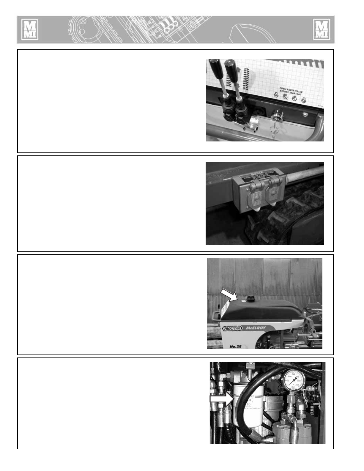
Facer
The facer is a McElroy Rotating Planer-Block design. The block
rotates on a ball bearing and is chain driven by a hydraulic
motor.
When fusing 4” and 6” diameter pipe on the TracStar no.412 or
No.618 move the facer blades to the inboard position.
TX01989-1-10-02
Insulated Heater Stand
The heater should always be stored in the insulated heater stand
or blanket for protection of the operator and to minimize heat loss
and risk of mechanical damage.
PH01915-11-15-00
PH02334-07-08-02
TX00363-9-15-94
2 - 6
Page 21

Overview
Heater
This Heater Is Not Explosion Proof. Operation
of heater in a hazardous environment without
necessary safety precautions will result in
explosion and death.
The heater temperature is controlled by a microprocessor. It has a
red indicator light on the handle at the bottom of the temperature
scale. When the heater is plugged in and preheating the light
glows steadily until the set temperature is reached. The light then
goes off and on slowly as the heater maintains temperature.
Coated butt fusion heater adapters are available for non-coated
heaters.
NOTICE: Non-coated heaters should never be used without butt
fusion heater adapters installed.
PH02334-7-08-02
To prevent a build-up of plastic pipe residue from accumulating
on the heater plates (loss of surface temperature and pipe sticking
may result), the heater plates should be cleaned with a nonsynthetic cloth before and after every fusion joint.
PH02313-7-08-02
PH02333-7-08-02
TX02033-7-08-02
2 - 7
Page 22

Operation
Read Before Operating
Before operating this machine, please read this manual
thoroughly and keep a copy available for future reference.
Return manual to the protective storage box when not in use. This
manual is to be considered part of your machine.
TX00401-9-15-94
Check Oil Level
Check oil level in the reservoir and verify that oil is visible in the
strainer.
Refer to the “Hydraulic Fluids” section of this manual for
hydraulic oil recommendations.
If oil is not visible in the reservoir strainer, fill reservoir until oil is
visible in the strainer.
Do not overfill reservoir.
Never allow dirt, water, or other foreign matter to enter the tank.
Use only clean oil from an unopened container.
TX02305-7-28-04
Stop-12-28-95
PH02710-07-29-04
Diesel Engine
Read the operating and maintenance instructions for the engine
before operating.
The key ignition has four positions. Preheat, off, run and start.
NOTICE: Set the engine to slow speed before starting. Never use
starting fluid.
Open facer valve and unplug the heater. Turn switch to preheat,
for five seconds. A horn will sound to signify low oil pressure.
Turn the key to the right to start the engine.
Turn the key to OFF to stop the engine.
TX01869-11-8-00
Gas Powered Units
Read the operating and maintenance instructions for the engine
before operating.
Set the engine speed to choke position. Open facer valve and
disconnect heater before starting engine. Turn key to start.
Gradually back off the choke position as engine warms up.
Turn key to stop.
PH01969-11-15-00
PH01926-11-15-00
TX01990-1-10-02
3 - 1
Page 23

Operation
Moving Machine Into Position
Make sure all personnel are safely clear of the machine before
moving.
Stand behind the machine console.
Move both track control levers forward to go in a straight line.
Release the levers to stop. Moving just the right track forward
turns the machine to the left. Moving just the left track forward
turns the machine to the right. Pull levers back to back up.
TX01491-3-2-98
Prepare Heater
Heater Is Not Explosion Proof. Operation of
heater in a hazardous environment without
necessary safety precautions will result in
explosion and death.
If operating in a hazardous environment, heater should
be brought up to temperature in a safe environment,
then unplugged before entering the hazardous
atmosphere for fusion.
Install butt fusion heater adapters.
NOTICE: The heater should never be used without butt fusion
heater adapters installed. Refer to the "Maintenance" section of
this manual for installation procedure.
Place heater in insulated heater stand.
Plug heater into the appropriate outlet on machine.
IMPORTANT: Engine must be in high speed to provide electric
power to the heater.
Refer to the "Maintenance" section of this manual for instructions
how to adjust heater temperature.
Allow heater to warm-up to operating temperature.
PH01969-11-15-00
PH02334-7-08-02
PH01922-11-15-00
TX01871-11-15-00
Set up Pipe Supports
Set up pipe stands and adjust height so the pipe is in line with the
jaws.
TX00367-9-15-94
3 - 2
PH01900-11-15-00
Page 24

Operation
Install Clamping Inserts
Select and install appropriate clamping inserts for the pipe that
is being fused.
TX00368-9-15-94
Check Hydraulic Pressure
The pressure gauge on the manifold block indicates the pressure
at the carriage valve. How much pressure depends on the
position of the selector valve and the pressure set on the specific
pressure reducing valve. With the selector valve up, the facing
pressure can be set. It may be necessary to adjust the carriage
pressure, while facing, with the top pressure reducing valve to
control facing pressure.
Shift the selector valve to the center position, and set the heating
pressure (if required). If heating pressure is not required, set the
pressure reducing valve at its lowest setting, or the drag pressure,
whichever is higher.
With the selector valve in the down position, the fusion pressure
can be set.
The heating and fusion pressures can be calculated using the
enclosed fusion pressure calculator. Always add drag pressure
to the calculated gauge pressure. Drag pressure should be
determined using the following procedure:
After facing the pipe, move the carriage so that the pipe ends are
approximately 2" apart.
Shift the carriage control valve to the middle (neutral) position.
Select the heating mode, and adjust the middle pressure reducing
valve to its lowest pressure by turning the valve counterclockwise.
Shift the carriage control valve to the left.
Gradually increase the pressure by turning the valve clockwise.
Increase the pressure until the carriage moves.
Quickly reduce the heating pressure valve counterclockwise until
the carriage is just barely moving.
Record this actual drag pressure.
Take the pressure, determined from the calculator, then add the
actual measured drag pressure. This will be the actual fusion
pressure to set with the bottom pressure reducing valve.
PH00304-9-24-93
CD00138B-9-12-94
PH01761-11-1-99
TX01894-11-15-00
3 - 3
Page 25

Operation
Loading Pipe Into Machine
Clean the inside and outside of pipe ends that are to be fused.
Open the upper jaws and insert pipe in each pair of jaws with
applicable inserts installed. Let the ends of the pipe protrude
about 1" past the face of the jaws.
Lower the pipe lifts then clamp the upper jaws.
TX00371-9-15-94
Positioning Pipe In Machine
Swing the facer into place. With the carriage control valve lever,
move the carriage toward the fixed jaws, while watching the gap
at each end of the facer rest buttons. When the pipe is in contact
with the facer, this gap indicates the amount of material that will
be trimmed from the pipe end. Assure sufficient material will be
removed for a complete face off. Tighten the clamp knobs on the
outside jaws. Hand tighten the inside clamp knobs.
PH01906-11-15-00
PH01904-11-15-00
TX00372-9-15-94
Facing the Pipe
Move the carriage to the right.
Open the ball valve on the facer motor.
Assure the selector valve handle is up in the facing position.
Move the carriage control valve to the left.
If the facer stalls, adjust the facing pressure so the facer continues to cut.
IMPORTANT: When drag pressure exceeds 300 psi it is necessary
to move the carriage to the left bringing the pipe ends into
contact with the facer before opening the facer valve.
Let the carriage bottom out on facer stops. Turn facer off. Move
the carriage to the right so the facer can be removed.
PH00361-9-12-94
PH01901-11-15-00
TX01872-11-8-00
3 - 4
Page 26

Operation
Remove Facer
Swing the facer out to the storage position.
Remove chips from pipe ends.
Do not touch faced pipe ends.
Inspect both pipe ends for complete face off. If the face off is
incomplete, return to Loading Pipe into Machine.
Move the carriage to the left until ends of pipe butt together.
Check pipe joint for proper alignment.
Do not use finger to check for hi/lo
(misalignment). The unit is under pressure, and
slippage could result in crushed fingers. Always
keep hands clear of the jaw area.
PH00362-9-14-94
PH00366-9-12-94
If pipe is not lined up, tighten the high side jaw to bring into
alignment.
IMPORTANT: Always tighten the side that is higher, never loosen
the low side.
When the pipe is properly aligned tighten outside clamps to
insure against slippage.
Ensure there is no unacceptable gap between the pipe ends.
If there is an unacceptable gap, return to Loading Pipe into
Machine.
NOTICE: When clamping, do not over-tighten the clamp knobs
because machine damage can result. Check to see if there is
space between the upper and lower jaws. If the two jaws are
touching, do not continue to tighten.
Bring the pipe ends together under fusion pressure to check
for slippage. If slippage occurs, return to Loading Pipe into
Machine.
PH00357-9-12-94
TX01873-11-15-00
PH00323-9-25-93
3 - 5
Page 27

Operation
Position Carriage for Heater Insertion
Move carriage to the right to open a gap large enough to insert
the heater.
TX00374-9-15-94
Check Heater Temperature
Incorrect heating temperature can result in
questionable fusion joints. Check heater plates
periodically with a pyrometer and make
necessary adjustments.
CD00138D-9-12-94
WR00077-4-16-93
Check heater surface temperature.
Refer to the pipe manufacturer's recommendations for proper
heater temperature.
IMPORTANT: The dial thermometer on the heater indicates internal
temperature which varies from the actual surface temperature.
The dial thermometer can be used as reference once the surface
temperature has been verified.
TX00375-11-1-94
Select the Fusion Position
Move selector valve handle down to the fusing position.
PH00420-11-1-94
TX00376-9-15-94
CD00138E-9-12-94
3 - 6
Page 28

Operation
Inserting Heater
Heater Is Not Explosion Proof. This unit is not
explosion proof. Operation of heater in a
hazardous environment without necessary safety
precautions will result in explosion and death.
If operating in a hazardous environment, heater
should be brought up to temperature in a safe
environment, then unplugged before entering the
hazardous atmosphere for fusion.
Use a clean non-synthetic cloth to clean the butt fusion heater
adapter surfaces.
Verify heater temperature by noting the reading on the dial
thermometer.
Insert heater between the pipe ends.
PH02333-7-08-02
PH01094-2-20-97PH00367-9-12-94
TX00377-9-15-94
Heating the Pipe
A) Move the carriage to the left, bringing the heater into
contact with both pipe ends.
B) Move selector valve to center position once contact is
established.
C) If heating pressure is not required, allow the pressure to
stabilize at the lowest setting and return carriage control
valve to neutral position.
CD00140-9-12-94
TX00874-11-8-00
3 - 7
Page 29

Operation
Fusing the Pipe
Failure to follow pipe manufacturer's heating
time, pressure, and cooling time may result in a
bad joint.
After following the pipe manufacturer's suggested heating
procedure:
A) Shift carriage control valve to neutral position.
B) Shift the selector valve down to fusion position.
C) Move the carriage to the right just enough to remove the
heater.
Quickly remove the heater.
D) Move the carriage to the left, bringing the pipe ends together
under the pipe manufacturer's recommended pressure.
CD00141B-9-12-94 CD00141A-9-12-94
Allow joint to cool under pressure according to pipe
manufacturer's recommendation.
TX00379-9-13-94
Opening Movable Jaws
After the joint has cooled for the pipe manufacturer's
recommended time, shift the carriage control valve to the neutral
position.
Loosen all clamp knobs, and move carriage to the right far
enough to open the jaw nearest the facer.
Open the movable jaws.
PH00363-9-12-94
PH00323-9-25-93
TX00380-9-15-94
3 - 8
Page 30

Operation
Opening Fixed Jaws
Open the fixed jaws.
TX00381-9-16-94
Raise Pipe
Raise the joined pipe using the pipe lift. Push down on the pipe
lift lever then release the latch. Pull the lever up to raise the pipe.
PH01903-11-15-00
PH01905-11-15-00
1
3
TX00382-9-16-94
Hydraulic Pipe Lifts
The TracStar® No.618 is equipped with two hydraulic pipe lifts
controlled by a valve mounted on the outer fixed jaw. When not
in use latch the valve in the down position.
TX01991-1-10-02
2
PH02369-9-19-02
3 - 9
Page 31

Operation
Position Pipe for Next Joint
Drive the fusion machine to end of pipe, or pull the pipe through
the jaws until the end of the pipe is protruding 1" past the jaw
face of the fixed jaw.
TX00383-9-15-94
Install Next Piece of Pipe
Insert a new piece of pipe in movable jaws and repeat all
previous procedures.
PH01906-11-15-00
PH00308-9-24-93
TX00384-10-12-95
3 - 10
Page 32

Special Operations - In Ditch
Disconnect Hydraulic Hoses
There are two sets of hydraulic hoses. One set connects to the
carriage hoses on the machine and to the carriage. The other set
connects to the facer hoses on the machine and to the facer.
Disconnect both sets of hoses.
®
For the TracStar
the outer fixed jaw by pulling the lower knob and rotating the
assembly.
no.618, disconnect pipe lift valve operator from
PH01911-11-15-00
TX011992-1-10-02
Remove Carriage Assembly from the Chassis
This equipment is not explosion proof. Operation
of this equipment in a hazardous environment
without necessary safety precautions will result in
explosion and death. See safety section.
The carriage can be easily removed from the machine for fusing
pipe on the ground or in the ditch. For especially tight conditions
it is also possible to remove the outer fixed jaws and skid. The
facer can be removed from the pivot shaft and used manually.
Remove Pin.
Attach lifting sling to the lifting points and the manifold bracket,
then lift the carriage assembly.
PH02369-9-19 -02
PH01908-11-15-00
PH01910-11-15-00
TX01876-11-15-00
PH01941-11-15-00
PH01937-11-15-00
4 - 1
Page 33

Special Operations - In Ditch
Remove 3-Jaw Assembly from the Carriage
Remove braces from inner fixed jaw.
Remove the four bolts holding carriage assembly to the chassis
with the wrench provided.
PH01939-11-15-00
PH01945-11-15-00
Attach lifting strap as shown and lift the carriage assembly.
PH01947-11-115-00PH01954-11-15-00
PH01949-11-15-00
TX01875-11-8-00
4 - 2
Page 34

Special Operations - In Ditch
Remove Facer From TracStar No.412
and No.618 Machine
Remove rear guide rod bracket.
Remove facer locking bolts.
PH01933-11-15-00
PH01907-11-15-00PH01936-11-15-00
Lift facer out of the carriage and set on cardboard or wood
blocks off of ground.
Attach rear guide rod bracket in the position shown.
TX01992-1-10-02
4 - 3
Page 35

Special Operations - In Ditch
Remove Facer From TracStar No.28 Machine
Loosen facer locking bolt.
Lift facer out of the carriage and set on cardboard or wood
blocks off of ground.
Remove rear guide rod bracket.
PH01930-11-15-00
PH01981-11-15-00PH01980-11-15-00
Attach rear guide rod bracket in the position shown.
TX01874-11-8-00
4 - 4
Page 36

Special Operations - In Ditch
Manual Facer Operation
Lift as shown.
Lock onto back guide rod, then latch on front guide rod.
PH019388-11-15-00PH01946-11-15-00
TX01887-11-15-00
4 - 5
Page 37

Special Operations - In Ditch
Removing Top Jaws
If the carriage is going to be hand carried, or if the carriage
needs to be hoisted and slid underneath the pipe, the top jaws
need to be removed.
Loosen all clamp knobs. Take out the detent pins securing the top
jaws and remove the jaws.
TX01479-2-26-98
Lower 3-Jaw or 4-Jaw Carriage into Ditch
Use all 4 jaws whenever possible. The three jaw unit should be
used only when space is not available for the entire carriage,
such as fusing onto a tee, an ell or doing saddle fusion
PH01305-3-12-98
PH01983-11-15-00
4-Jaw
Attach lifting sling to the manifold bracket and the near side lift
point.
Lift carriage assembly and lower into ditch.
3-Jaw
Attach lifting sling to the manifold bracket.
Lift carriage assembly and lower into ditch.
TX01864-9-29-00
PH01984-11-15-00
4 - 6
Page 38

Special Operations - In Ditch
Clamp Carriage Assembly to Pipe
Position carriage assembly on side of the pipe. Lift pipe and slide
carriage assembly under pipe.
Rotate carriage assembly around to a normal upright position.
CD00193b-2-19-96CD00194b-2-19-96CD00195a-2-19-96
Attach the top jaws and loosely clamp around pipe.
TX00879-2-19-96
4 - 7
Page 39

Special Operations - In Ditch
Attach Hydraulic Hoses
There are two sets of hydraulic extension hoses. One set connects
to the carriage hoses on the machine and to the carriage. The
other set connects to the facer hoses on the machine and to the
facer.
Connect all hoses.
TX01485-2-26-98
Make Fusion Joint
Refer to the "Butt Fusion Procedure" for operating instructions.
After facing operation, remove the facer from ditch.
PH01908-11-15-00
PH00363-9-12-94
TX00450-9-16-94
Remove Carriage Assembly from Ditch
Loosen clamp knobs and remove top jaws.
Rotate carriage assembly from under the pipe.
IMPORTANT: Always rotate unit with valve system facing up to
protect against damage.
Attach sling to lifting point(s).
Lift carriage assembly from ditch.
TX00451-9-16-94
Reassemble Fusion Machine
Install carriage assembly to the chassis and connect carriage hoses.
Lift facer into position and bolt to facer mount. Do not tighten. Pivot
facer down and bring jaws inward against the facer to establish
facer position. Open jaws away from facer and pivot facer out.
Tighten the facer mounting bolts.
Connect facer hoses.
Install pipe lift operator on the TracStar® no.618
Replace top jaws.
CD00193b-9-29-00
PH01907-11-15-00
TX01993-1-10-02
4 - 8
Page 40

Special Operations
- Saddle Fusion Procedure
Saddle Fusion Procedure for TracStar No.28CU
The combination unit is capable of saddle fusing up to an 8"
(200 mm) branch on any size main.
TX00454-9-22-94
Install Heater Adapters
Heater is Not Explosion Proof. Operation of
heater in a hazardous environment without
necessary safety precautions will result in
explosion and death.
If operating in a hazardous environment, heater
should be brought up to temperature in a safe
environment, then unplugged before entering the
hazardous atmosphere for fusion.
Select appropriate heater and sidewall fusion heater adapters.
Clean heater surfaces and adapter surfaces. Attach the adapters
to the heater.
Place heater in insulated heater blanket.
Plug heater into the vehicle.
IMPORTANT: Engine must be in high speed to provide electric
power to the heater.
PH00406-9-21-94
PH00416-11-1-94
TX01888-11-15-00
Assure Saddle Will Fit
For branch saddles, a nipple long enough to extend through
both movable jaws should be fused to the fitting using standard
butt fusion procedures.
TX00456-9-15-94
5 - 1
PH00418-11-1-94
PH00423-11-1-94
Page 41

Special Operations
-
Install Clamping Inserts
Select and install appropriate clamping inserts in the movable
jaw(s).
TX00457-9-16-94
Remove Carriage Assembly from Vehicle
Use lifting sling and detach carriage from vehicle.
Refer to pg. 4-1
Saddle Fusion Procedure
PH00304-9-23-93
PH01937-11-15-00
TX01880-11-10-00
Attach Carriage Assembly to Main
Place the machine on the main.
Place a line bolster on main opposite the carriage assembly if
required.
Position the tailstock chains around the main and lock into the
chain hooks.
Tighten the machine onto the main using the tailstock clamp
knobs.
TX00458-9-16-94
Set Hydraulic Pressure
Check hydraulic pressure. Shift the selector valve to the center
position to set the pressure for heating (if heating pressure
differs from fusion pressure). With the selector valve in the down
position, the fusion pressure can be set.
Consult the pipe manufacturer for proper pressures.
PH00387-9-21-94
CD00138B-9-12-94
TX00459-9-16-94
5 - 2
Page 42

Special Operations
- Saddle Fusion Procedure
Clean Surfaces
Use 50 or 60 grit utility cloth to clean and rough the main to
expose fresh material.
Rough the base of the fitting unless the manufacturer specifies
otherwise.
Surface must be free of water and oil.
TX01879-11-10-00
Clamp Fitting
Position the fitting, and bolster if required, loosely in the movable
jaw(s). Move the carriage to the right to properly position the
fitting on the main. Tighten the clamp knobs.
Be sure to allow enough travel for the melt pattern and fusion to
occur (3/4" min.).
PH00400-9-21-94
PH00399-9-21-94
TX00461-9-15-94
Test for Slippage
Bring the fitting against the main under full fusion pressure
to insure that no slippage or movement of the main or fitting
occurs.
TX00462-9-14-94
PH00390-9-21-94
5 - 3
Page 43

Special Operations
- Saddle Fusion Procedure
Prepare Heater
Heater is Not Explosion Proof. Operation of
heater in a hazardous environment without
necessary safety precautions will result in explosion
and death.
If operating in a hazardous environment, heater
should be brought up to temperature in a safe
environment, then unplugged before entering the
hazardous atmosphere for fusion.
Use a clean non-synthetic cloth to clean the saddle fusion heater
adapter surfaces.
Verify heater temperature by noting the reading on the dial
thermometer.
Check the heater temperature and install heater between the
fitting and main. Assure proper line-up.
PH00389-9-21-94
PH00417-11-1-94
TX00463-9-16-94
Heat Pipe and Fitting
Move selector valve to the center position, if pressure during the
heat cycle differs from fusion pressure. Move the carriage to the
right to bring the fitting in contact with the heater and the heater
in contact with the main. The carriage control valve lever must
be positioned in the right hand position to maintain pressure.
Establish proper melt pattern as specified by the material
supplier.
TX00464-9-14-94
Remove Heater
Shift the carriage control valve to neutral and then the selector
valve down to the fusion position. Move the carriage to the left
just enough to remove the heater.
PH00402-9-21-94
PH00404-9-21-94
TX00465-9-14-94
5 - 4
Page 44

Special Operations
- Saddle Fusion Procedure
Fuse Fitting to Pipe
Remove the heater with a snap action and quickly inspect the
melt pattern. Quickly move the carriage to the right bringing
the fitting and main together under the pipe manufacturer's
recommended pressure.
TX00466-9-14-94
Allow Joint to Cool
Allow the joint to cool under pressure as specified by the pipe
manufacturer. To maintain fusion pressure during cooling, the
carriage control valve must be positioned in the right hand
direction.
PH00403-9-21-94
PH00405-9-21-94
TX00467-9-14-94
5 - 5
Page 45

Special Operations
Heavy Overhead Load
Fusion machine and plastic pipe are heavy. If
loaded or lifted improperly, they could crush or
kill. Handle load carefully with proper overhead
rigging and equipment of adequate load rating.
TX00062-3-8-93
Crush Points
Crush points exist on this machine. Keep hands
and body parts away from the machine. Be
aware of yourself and others when moving
equipment.
- Lifting Fusion Machine
WR00014-3-8-93
WR00012-12-4-92
TX01895-11-15-00
Required Equipment
❏ Proper overhead rigging and equipment of adequate
load rating to lift the fusion machine.
❏ Lifting Sling - (supplied with machine)
Notice: Check all equipment to confirm that it is in good working
order.
PH01955-11-15-00
TX01881-11-10-00
6 - 1
Page 46

Special Operations
- Lifting Fusion Machine
Attach Slings
Attach the sling to the pick-up points. The cables are color coded
to the chassis. Connect the yellow cables to the yellow lift points,
etc. For machines that are not color coded, attach the longest
leg cable at position A and the shortest leg cable at position B.
When lifting the TracStar® No.618, pivot the facer out before
attaching the lifting sling. The cable attached at position A will
run through the inner fixed jaw. Small pipe diameter inserts in
the upper fixed jaw may need to be removed to prevent the
cable from deflecting.
TX02059-9-19-02
Lifting Safety
Follow all applicable federal, state, local, and industry specific
regulations when lifting unit.
Never carry loads over people.
A
B
PH01937-11-15-00
C
SAFE1ST-12-14-92
TX00410-10-12-93
6 - 2
Page 47

Maintenance
Preventative Maintenance
To insure optimum performance, the machine must be kept clean
and well maintained.
With reasonable care, this machine will give years of service.
Therefore, it is important that a regular schedule of preventive
maintenance be kept.
Store machine inside, out of the weather, whenever possible.
TX00428-8-10-95
Washing the Machine
The machine should be cleaned, as needed with a soap and
water wash.
CD00142-11-2-94
CD00178-9-29-00
TX00429-9-15-94
Check Hydraulic Fluid
The hydraulic fluid level should be checked daily.
If hydraulic oil is not visible in the reservoir strainer.
Refer to the "Hydraulic Fluids" section of this manual for hydraulic
oil recommendations.
If oil is not visible in the reservoir strainer, fill reservoir until oil is
visible in the strainer. Do not overfill reservoir.
Never allow dirt, water or other foreign matter to enter the tank.
Use only clean oil from an unopened container.
TX02307-7-28-04
Change Hydraulic Fluid and Filter
The hydraulic fluid and filter should be replaced after every 400
hours of operation.
Fluid should also be changed as extreme weather conditions
dictate.
Refer to the "Hydraulic Fluids" section of this manual for hydraulic
oil recommendations.
PH02710-07-29-04
PH01916-11-15-00
TX00431-9-15-94
7 - 1
Page 48

Maintenance
Install/Remove Covers
Hook top of cowl on three clips. Align the thumbscrew in the
socket and tighten.
Align the rear latches and fasten the latch, making sure it locks.
The cowl should be outside the dash panel
PH01976-11-15-00
PH01974-11-15-00PH01975-11-15-00
Align and fasten the front latch the same way.
Reverse the procedure to remove the cowls.
PH02245-1-10-02
TX01994-1-10-02
7 - 2
Page 49

Maintenance
Engine Belt Tension Adjustment
Check the engine belt tension every 100 hours of operation. A
force of 7lb. should deflect the belt 1/8 inch. If oil has gotten on
the belt it will need to be replaced.
TX01996-1-10-02
Tensioning the Belt
The tensioner is located beside the rear pipe lift. Loosen the jam
nut and tighten the belt as noted above. Lock the jam nut after
adjusting
NOTICE: Overtightening will cause premature failure of engine
and alternator bearings. Under tightening will cause chirpping
and belt slippage.
PH01918-11-15-00
PH01957-11-15-00
TX01997-1-10-02
Adjusting System Pressure
Remove the right side engine cover to gain access to the
hydraulic pump.
Start the engine and select high speed.
The system pressure should be at 1800 psi on TracStar® No.28 &
No.412 and 2000 psi on the TracStar® No.618 units.
To adjust the pressure, loosen the jam nut and turn the
compensator to the right to increase the pressure, or to the left to
decrease pressure. Retighten the jam nut.
PH01917-11-15-00
TX01998-1-10-02
7 - 3
Page 50

Maintenance
Engine Oil System - Diesel
Change engine oil and filter after the first 50 hours of operation.
After the first oil change, change the oil and filter every 200
hours of operation. Read the engine maintenance instructions.
Use appropriate single weight oil for the ambient temperature.
The oil filter is located behind the engine access panel.
The oil drain plug is located on the bottom of the oil pan.
The oil filler cap and dip stick are located on top of the engine.
TX01884-11-10-00
PH01914-11-15-00
Engine Oil System - Gasoline
Change engine oil after the first 20 hours of operation. After
the first oil change, change the oil and filter every 100 hours of
operation. Read the engine maintenance instructions.
Use appropriate single weight oil for the ambient temperature.
The oil drain plug is located on the bottom of the oil pan.
The oil filler cap and dip stick are located on top of the engine.
TX01900-11-15-00
PH01971-11-15-00
7 - 4
Page 51

Maintenance
Check Gauge Calibration
Gauge calibration should be checked daily.
The gauge should read zero when the unit is not running.
Damaged gauges should be replaced.
TX00432-9-13-94
Clean Jaws and Inserts
To prevent slippage and insure proper alignment, the jaws and
inserts must be clean.
Clean the jaws and inserts of any dirt or residual material using
a stiff-bristled brush.
PH01972-11-15-00
PH00304-9-24-93PH00377-9-14-94
TX00433-9-15-94
Clean Thrust Bearings
The thrust bearings located in the clamp knobs must turn freely.
Wash the clamp knob bearing assembly with a solvent, and then
lubricate with 30W or lighter oil.
TX00434-9-13-94
Clean Eyebolt Threads
Keep the clamp knob eyebolt threads brushed clean.
PH00377-9-14-94
TX00435-9-13-94
7 - 5
Page 52

Maintenance
Clean the Clamping Chains
On the combination unit clean the side fusion chains as needed.
Clean using a stiff-bristled brush and oil generously. Wipe away
any excess oil.
TX00436-9-13-94
Fasteners Must Be Tight
Check all nuts, bolts, and snap rings to make certain they are
secure and in place.
PH00378-9-14-94
PH00433-11-1-94
TX00437-9-13-94
Facer Blades
Blades bolt directly to the blade holder and should be inspected
for damage and sharpness.
Dull or chipped blades must be replaced.
TX00439-9-13-94
Check/Add Antifreeze
Add antifreeze in a 50/50 mix with water as needed on diesel
units.
Replace antifreeze mixture once each year or as recommended in
engine manual.
PH01912-11-15-00
PH01903-11-15-00
TX01897-11-15-00
7 - 6
Page 53

Maintenance
Clean Heater Surfaces
The heater faces must be kept clean and free of any plastic build
up or contamination.
Before and after each fusion joint the heater surfaces must be
wiped with a clean, non-synthetic cloth.
NOTICE: Do not use an abrasive pad or steel wool. Use a nonsynthetic cloth that won't damage surfaces.
TX00440-9-13-94
Bleeding Air From Hydraulic System
The two carriage cylinders have air bleed screws and must be
bled if the system ever runs low on oil or leaks air on inlet side
of pump. Air in the system is indicated when carriage movement
becomes jerky and erratic. To bleed the system, proceed as
follows:
Remove upper jaws & clamping eye bolts from the two movable
clamp jaws to expose the bleed plugs recessed in top of the
lower jaws.
Tilt machine so the fixed jaw end is higher than the opposite end.
Shift the directional control and move the carriage to the fixed
jaw end. Adjust the pressure to approximately 50-100 psi before
proceeding.
Loosen the bleed plug on one cylinder next to the fixed jaw.
Hold pressure on the cylinder until no air is indicated and quickly
tighten the plug.
Repeat this operation on the opposite cylinder.
Tilt the machine so the opposite end is higher than the fixed jaw
end. Move the carriage to the end opposite the fixed jaw and
repeat the above procedure on the this end of the cylinders.
PH02333-7-08-02
PH01991-11-15-00
PH01992-11-15-00
TX00427-9-15-94
7 - 7
PH01993-11-15-00
PH01994-11-15-00
Page 54

Maintenance
Installing Butt Fusion Heater Adapters
The heater body of this assembly is not coated. Coated butt
fusion heater plates are available for all butt fusion applications.
Butt fusion heater adapters are installed with Stainless Steel Cap
Screws.
Care should be taken to assure that the butt fusion heater
adapters are seated on the heater body, and that there is no
foreign matter trapped between these surfaces.
IMPORTANT: Do not over tighten the bolts.
The surface of the butt fusion heater adapters are coated with an
antistick coating.
TX01899-11-15-00
Adjusting Heater Temperature
Turn knob to desired temperature. Measure the heater surface
temperature with a pyrometer. Any variance must be corrected
to the pyrometer reading.
Loosen setscrew in the knob. Turn knob to point to the same
temperature as the pyrometer. Tighten setscrew in the knob.
Turn knob to desired temperature. Allow heater to stabilize at
the new temperature (5 to 10 minutes) after adjusting.
The thermometer on the heater body indicates internal
temperature and should be used as a reference only.
TX02034-7-08-02
PH02333-7-08-02
PH02313-7-08-02
Heater Indicator Light
The heater has a red indicator light on the handle at the bottom
of the temperature scale. When the heater is plugged in and
preheating the light glows steadily until the set temperature is
reached. The light then goes off and on slowly as the heater
maintains temperature.
If the heater is not operating properly, the control will attempt
to turn the heater off and the indicator light will flash rapidly.
If this occurs, disconnect the power and take it to a McElroy
Authorized Service Center for repair.
TX02035-7-08-02
7 - 8
PH02314-7-08-02
INDICATOR LIGHT
PREHEATING
AT SET POINT
ERROR
PH00482-8-16-95
Page 55

Maintenance
Engine Maintenance
Refer to the operation and maintenance manual for the engine.
TX01500-3-5-98
Checking Track Tension
PH01960-11-15-00
Park the machine on a flat solid surface.
Use the lifting sling to raise machine off the ground.
Place adequate supports under the the bottom frame after lifting.
Measure the deflection between the bottom center roller and the
inside surface of the rubber track. Track tension is normal when
this distance is about 1/2". If the deflection is more or less than
this, the tension needs to be adjusted.
TX01885-11-10-00
CD00463-2-25-98
7 - 9
Page 56

Maintenance
Adjusting Track Tension
The grease in the hydraulics of the track is
pressurized. If the grease valve is loosened too
much, grease can be expelled at high pressure
and cause serious injury. Never loosen grease
valve more than one turn. Injury could also
result if the grease nipple is loosened. Never
loosen the grease nipple.
Remove screws and cover to access the adjustment system.
To loosen the track, turn hex shaped valve counterclockwise
no more than 1 turn. If grease does not start to drain out, then
slowly rotate the track. When correct track tension is obtained,
turn valve clockwise and tighten it. Clean off any expelled
grease.
①
PH01283-2-25-98
①
To tighten the track, connect a grease gun to the nipple and
add grease to the system. When the track stretches to the
correct tension, stop adding grease. Clean off any excess
grease.
Replace access cover.
TX01898-11-15-00
②
Setting Engine Speed
With the engine running at max speed plug the heater in. Put a
volt meter in the unused receptacle. Make sure the throttle is in the
detented position.
②
PH01979-11-15-00
PH01987-11-15-00
Adjust throttle cable sheath until voltage is correct.
The TracStar No.412 and No.618 should read 120V±2.
The TracStar No.28 should read 240V±4.
TX01906-11-15-00
7 - 10
PH01986-11-15-00
Page 57

Maintenance Checklist
Fusion Machine Checklist
Items to Check Satisfactory Needs Repair Comments
Repair
UNIT
Machine is clean
All pins and snaprings are in place
All nuts and bolts are tight
All identification placards and handles are in place
All clamp knobs are lubricated and turn freely
Wiring, battery cables, & all electrical terminals
Cords and plugs are in good condition
All hardware is on the basic machine
Hydraulic oil level is correct
No oil or water leaks (engine and hydraulic system)
Hydraulic gauge reads correctly
Rubber tracks in good condition
Fuel tank full
Engine crankcase is filled to correct level
Cooling system level is correct
Hydraulic hoses are in good condition
Engine starts and runs properly
Jaws are properly aligned
Facer pivot operates properly
Facer operates smoothly
Face-off is square
Inserts fit and pin properly
Voltage to heater is correct
Carriage and Selector Valves operate smoothly
Pressure Reducing Valves operate in their range
Heater Cord and plug are in good condition
Heater surface is clean and in good condition
Thermometer is in good working order
Surface temperature checked with pyrometer
Throttle control works properly
Low Oil /alarm works (diesel only)
Primary pump pressure (1800 psi)
Hydraulic carriage works smoothly
Check receptacles for damage
TX01866-9-29-00
8 - 1
Page 58

Determining Fusion Pressure
Variable Definitions
O.D. = Outside Diameter
t = Wall Thickness
∏ = 3.1416
SDR = Standard Dimensional Ratio
IFP = Manufacturer’s Recommended
Interfacial Pressure
TEPA = Total Effective Piston Area
Formulas
O.D.
t = ------------
SDR
AREA = (O.D. - t) x t x ∏
FORCE = AREA x IFP
(O.D. - t) × t × ∏ × IFP
GAUGE PRESSURE = ----------------------------------------------- + 30 P.S.I. DRAG
TEPA
Example
Pipe Size = 8" IPS
O.D. of Pipe = 8.625
SDR of Pipe = 11
Recommended Interfacial Pressure = 75 PSI
Using a Model 28 Fusion Unit
O.D. 8.625
t = ------------- = --------------- = 0.784
SDR 11
TEPA = 4.710 (From Table)
(O.D. - t) × t × ∏ × IFP
GAUGE PRESSURE = ----------------------------------------------- + 30 P.S.I. DRAG
TEPA
Fusion High Force Medium Low Force
Model (Standard) Force (High (Extra High
Velocity) Velocity)
28 4.71 - 1.67
412 11.78 6.01 3.14
618 11.78 6.01 3.14
824 29.44 15.32 9.45
1236 29.44 15.32 9.45
1648 31.42 14.14 -
2065 31.42 - -
Total Effective Piston Areas
(8.625. - .784) × .784 × 3.1416 × 75
GAUGE PRESSURE = -------------------------------------------------------------------------------- + 30 P.S.I. DRAG = 338 PSI
4.710
TX00343-12-9-93
9 - 1
Page 59

Hydraulic Fluids
Hydraulic Fluids
The use of proper hydraulic oil is mandatory to achieve maximum performance and machine life. Use a clean, high
quality, anti-wear hydraulic oil with a viscosity index (VI) of 135 minimum. It should have a maximum viscosity of
500 cSt (2000 SSU) at startup (ambient temperature) and a minimum viscosity of 13 cSt (65 SSU) at the maximum
oil temperature (generally 80°F above ambient). Using hydraulic oils that do not meet these criteria may cause poor
operation and/or damage to the hydraulic components.
The following table specifies the oil temperature at various viscosities. Temperature rise of the hydraulic oil can vary
from 30° F to about 80° F over the ambient temperature depending on the pressure setting, age of the pump, wind,
etc. Exxon Univis N46 hydraulic oil is installed at our factory. The advantage of this oil is a wider temperature
range, however, this oil should not be used for continuous operation below 20° F. For use in extremely cold ambient
temperatures, we suggest Mobil DTE 11M, which can be used to –16° F. This oil should not be used for continuous
operation above 100° F (oil temperature).
TX02244-2-2-04
Hydraulic Fluids Characteristics
Manufacturer Fluid Name SSU SSU V.I. -20F -10F 0F 10F 30F 50F 70F 90F 110F 130F 150F Range
100F 210F °F
Mobil DTE 11M 87 40 145 ******************************************* -27-87
DTE 13M 165 48 140 ***************************************** 5-130
DTE 15M 225 53 140 ********************************************* 5-140
Exxon Univis N-32 177 49 164 ********************************************* 5-140
Univis N-46 233 55 163 ************************************* 25-142
Univis N-68 376 68 160 ************************************** 34-155
NOTE: This chart is based on pump manufacturer recommendations of 65 to 2000 SSU limits.
NOTE: Temperatures shown are fluid temperatures. – NOT ambient temperatures.
10 - 1
Page 60

Specifications
0
100
200
300
400
500
600
700
800
900
1000
0
100
200
300
400
500
600
700
800
900
1000
DIRECTIONAL
CONTROL
VALVE
FACING
PRESSURE
HEATING
PRESSURE
FUSING
PRESSURE
SELECTOR
VALVE
TracStar® No.28 Fusion Machine
Specifications:
Engine: 11HP, OHV, Air Cooled
Starting System: Electric and Recoil
Fuel Type: Gasoline
Fuel Tank Capacity: 5 Gals.
Operational Tank Capacity: 8 Hrs.
System Pressure: 1750 PSI
Hydraulic Reservoir Capacity: 8 Gals
Vehicle Speed: 2.5 MPH
AC Output: 120V & 240 V, 60Hz, 15 Amp
47.4''
1204mm
33''
838mm
43''
1092mm
44''
1118mm
762mm
30''
96''
2438mm
Entire Machine
3-jaw Carriage Weight: 185 lbs (83.9kg)
4-jaw Carriage Weight: 230 lbs (104.3kg)
Facer Weight: 39 lbs (17.7kg)
Heater Weight: 17 lbs (7.7kg)
Weight: 1320 lbs (598.7kg)
TracStar® No.412 Fusion Machine Specifications:
Engine: 18.5 HP Liquid cooled
Starting System: Electric
Fuel Type: Diesel
Fuel Tank Capacity: 5 Gals.
Operational Tank Capacity: 8 Hrs.
System Pressure: 1750 PSI
Hydraulic Reservoir Capacity: 8 Gals
Vehicle Speed: 2.5 MPH
AC Output: 120 & 240V, 60Hz, 15 Amp
Entire Machine
Weight: 1
,500 lbs (680kg)
50.4''
1280mm
33''
838mm
48.5''
1232mm
44''
1118mm
762mm
30''
DIRECTIONAL
CONTROL
VALVE
SELECTOR
FACING
PRESSURE
HEATING
VALVE
PRESSURE
FUSING
PRESSURE
22438mm
96''
3-jaw Carriage Weight: 283 lbs (128.4kg)
4-jaw Carriage Weight: 343 lbs (155.6kg)
Facer Weight: 57 lbs (25.6kg)
Heater Weight: 22 lbs (10kg)
11 - 1
Page 61

Specifications
TracStar® No.618 Fusion Machine
Specifications:
Engine: 18.5 HP Liquid Cooled
Starting System: Electric
Fuel Type: Diesel
50.4''
Fuel Tank Capacity: 5 Gals.
Operational Tank Capacity: 8 Hrs.
System Pressure: 2000 PSI
Hydraulic Reservoir Capacity: 8 Gals
Vehicle Speed: 1.5 MPH
AC Output: 120V & 240 V, 60Hz, 15 Amp
1280mm
42.5''
1080mm
52''
1320mm
44''
1118mm
762mm
98.5''
2502mm
30''
Entire Machine
3-jaw Carriage Weight: 363 lbs (165kg)
4-jaw Carriage Weight: 441 lbs (200kg)
Facer Weight: 89 lbs (40kg)
Heater Weight: 29 lbs (13.2kg)
Weight: 2000 lbs (909kg)
11 - 2
Page 62

About this manual . . .
McElroy Manufacturing continually strives to give customers the best quality products
available. This manual is printed with materials made for durable applications and harsh
environments.
This manual is waterproof, tear resistant, grease resistant, abrasion resistant and the bonding
quality of the printing ensures a readable, durable product.
The material does not contain any cellulose based materials and does not contribute to the
harvesting of our forests, or ozone-depleting constituents. This manual can be safely disposed
of in a landfill and will not leach into ground water.
TX001660-8-19-99
Page 63

 Loading...