


Operator’s
Manual
Fusion Machine
Original Language: English
Manual: T5019210 Revision: Rev C 11/18
This product and other products
could be protected by patents or
have patents pending. All the latest
patent information is available at
patent.mcelroy.com
Introduction
Thank You for purchasing this McElroy product
The TracStar® 500 series 3 is a self-contained, self-propelled, all
terrain fusion machine, and is designed to produce consistently
high quality polyolefin pipe butt fusion joints with a minimum of
operator effort.
The TracStar® 500 series 3 fuses 6” IPS (180mm) minimum to 20”
IPS (500mm) maximum pipe.
With reasonable care and maintenance, this machine will give
years of satisfactory service.
Before operating this machine, please read this manual thoroughly,
and keep a copy with the machine for future reference. This manual
is to be considered part of your machine.
Always return the manual to the literature compartment.
TX04535-10-24-12
McElroy University
For more than 30 years, McElroy has been the only
pipe fusion machine manufacturer to continuously
offer advanced training. Course offerings are meant to
enhance your efficiency, productivity and safety in the
proper use of McElroy machines. McElroy University
classes are structured so that the skills learned and the
machines used in each class closely match the machines
found on pipelining jobsites. We offer training at
our facility or yours. Our uniquely qualified McElroy
University course instructors offer years of industry
experience.
Tuition for each course includes lunches, course materials
and a certificate of completion. Online registration,
as well as up-to-date course offerings and dates, is
available at www.mcelroy.com/university
This manual is intended as a guide only and does not
take the place of proper training by qualified instructors.
The information in this manual is not all inclusive and
can not encompass all possible situations that can be
encountered during various operations.
MU2-03-13-14
TX04659-03-24-14

Warranty
LIMITED WARRANTY
McElroy Manufacturing, Inc. (McElroy) warrants all
products manufactured, sold and repaired by it to be
free from defects in materials and workmanship, its
obligation under this warranty being limited to repairing
or replacing at its factory and new products, within 5
years after shipment, with the exception of purchased
items (such as electronic devices, pumps, switches, etc.),
in which case that manufacturer’s warranty applies.
Warranty applies when returned freight is prepaid and
which, upon examination, shall disclose to have been
defective. This warranty does not apply to any product
or component which has been repaired or altered by
anyone other than McElroy or has become damaged
due to misuse, negligence or casualty, or has not been
operated or maintained according to McElroy’s printed
instructions and warnings. This warranty is expressly in
lieu of all other warranties expressed or implied. The
remedies of the Buyer are the exclusive and sole remedies
available and Buyer shall not be entitled to receive any
incidental or consequential damages. Buyer waives
the benefit of any rule that disclaimer of warranty shall
be construed against McElroy and agrees that such
disclaimers herein shall be construed liberally in favor of
McElroy.
RETURN OF GOODS
Buyer agrees not to return goods for any reason except
upon the written consent of McElroy obtained in advance
of such return, which consent, if given, shall specify the
terms and conditions and charges upon which any such
return may be made. Materials returned to McElroy, for
warranty work, repair, etc., must have a Return Material
Authorization (RMA) number, and be so noted on the
package at time of shipment. For assistance, inquiry shall
be directed to:
McElroy Manufacturing, Inc.
P.O. Box 580550
833 North Fulton Street Tulsa, Oklahoma 74158-0550
PHONE: (918) 836–8611, FAX: (918) 831–9285.
EMAIL: fusion@McElroy.com
Note: Certain repairs, warranty work, and inquiries may
be directed, at McElroy’s discretion, to an authorized
service center or distributor.
DISCLAIMER OF LIABILITY
McElroy accepts no responsibility of liability for fusion
joints. Operation and maintenance of the product is the
responsibility of others. We recommend qualified joining
procedures be followed when using McElroy fusion
equipment.
McElroy makes no other warranty of any kind whatever,
express or implied; and all implied warranties of
merchantability and fitness for a particular purpose which
exceed the aforestated obligation are hereby disclaimed
by McElroy.
PRODUCT IMPROVEMENT
McElroy reserves the right to make any changes in or
improvements on its products without incurring any
liability or obligation to update or change previously sold
machines and/or the accessories thereto.
INFORMATION DISCLOSED
No information of knowledge heretofore or hereafter
disclosed to McElroy in the performance of or in
connection with the terms hereof, shall be deemed to be
confidential or proprietary, unless otherwise expressly
agreed to in writing by McElroy and any such information
or knowledge shall be free from restrictions, other than a
claim for patent infringement, is part of the consideration
hereof.
PROPRIETARY RIGHTS
All proprietary rights pertaining to the equipment or
the components of the equipment to be delivered by
McElroy hereunder, and all patent rights therein, arising
prior to, or in the course of, or as a result of the design
or fabrication of the said product, are exclusively the
property of McElroy.
LAW APPLICABLE
All sales shall be governed by the Uniform Commercial
Code of Oklahoma, U.S.A.
Register your product online to activate your warranty:
www.McElroy.com/fusion
(Copy information listed on the machine nameplate here
for your records).
TX02486-11-4-13
Model No.
Serial No.
Date Received
Distributor

Fusion Equipment Safety
Safety Alerts . . . . . . . . . . . . . . . . . . . . . . . . . . . . . . . . . . . . . . . . . . 1-1
Read and Understand. . . . . . . . . . . . . . . . . . . . . . . . . . . . . . . . . . . . 1-1
General Safety . . . . . . . . . . . . . . . . . . . . . . . . . . . . . . . . . . . . . . . . 1-2
Wear Safety Equipment . . . . . . . . . . . . . . . . . . . . . . . . . . . . . . . . . . 1-2
Fuel Handling . . . . . . . . . . . . . . . . . . . . . . . . . . . . . . . . . . . . . . . . . 1-2
Units with Engines . . . . . . . . . . . . . . . . . . . . . . . . . . . . . . . . . . . . . . 1-3
Carbon Monoxide . . . . . . . . . . . . . . . . . . . . . . . . . . . . . . . . . . . . . . 1-3
Heater is Not Explosion Proof . . . . . . . . . . . . . . . . . . . . . . . . . . . . . . 1-3
Crush Points . . . . . . . . . . . . . . . . . . . . . . . . . . . . . . . . . . . . . . . . . . 1-3
Battery . . . . . . . . . . . . . . . . . . . . . . . . . . . . . . . . . . . . . . . . . . . . . . 1-4
Electrical Safety . . . . . . . . . . . . . . . . . . . . . . . . . . . . . . . . . . . . . . . . 1-4
Units with Hydraulics . . . . . . . . . . . . . . . . . . . . . . . . . . . . . . . . . . . . 1-5
Pipe Handling Safety . . . . . . . . . . . . . . . . . . . . . . . . . . . . . . . . . . . . 1-5
Facer Blades Are Sharp . . . . . . . . . . . . . . . . . . . . . . . . . . . . . . . . . . 1-6
Keep Machine Away From Edge of Ditch . . . . . . . . . . . . . . . . . . . . . . 1-6
Operating Fusion Machine . . . . . . . . . . . . . . . . . . . . . . . . . . . . . . . . 1-6
Heater is Hot . . . . . . . . . . . . . . . . . . . . . . . . . . . . . . . . . . . . . . . . . . 1-7
Do Not Attempt to Tow Fusion Machine . . . . . . . . . . . . . . . . . . . . . . . 1-7
Fusion Procedures . . . . . . . . . . . . . . . . . . . . . . . . . . . . . . . . . . . . . . 1-7
Table of Contents
Overview
Theory of Heat Fusion . . . . . . . . . . . . . . . . . . . . . . . . . . . . . . . . . . . 2-1
TracStar® 500 series 3 Console . . . . . . . . . . . . . . . . . . . . . . . . . . . . 2-2
Auto Throttle . . . . . . . . . . . . . . . . . . . . . . . . . . . . . . . . . . . . . . . . . . 2-2
Alternate Drive Controls . . . . . . . . . . . . . . . . . . . . . . . . . . . . . . . . . . 2-2
Pipe Lift Controls . . . . . . . . . . . . . . . . . . . . . . . . . . . . . . . . . . . . . . . 2-3
Carriage Assembly . . . . . . . . . . . . . . . . . . . . . . . . . . . . . . . . . . . . . . 2-3
Indexer Controls . . . . . . . . . . . . . . . . . . . . . . . . . . . . . . . . . . . . . . . . 2-3
Inlet Fans . . . . . . . . . . . . . . . . . . . . . . . . . . . . . . . . . . . . . . . . . . . . 2-4
Facer . . . . . . . . . . . . . . . . . . . . . . . . . . . . . . . . . . . . . . . . . . . . . . . 2-4
Hydraulic Manifold Block . . . . . . . . . . . . . . . . . . . . . . . . . . . . . . . . . 2-4
Heater . . . . . . . . . . . . . . . . . . . . . . . . . . . . . . . . . . . . . . . . . . . . . . 2-5
Diesel Engine . . . . . . . . . . . . . . . . . . . . . . . . . . . . . . . . . . . . . . . . . 2-6
Hydraulic Fluid Reservoir . . . . . . . . . . . . . . . . . . . . . . . . . . . . . . . . . . 2-6
Filter . . . . . . . . . . . . . . . . . . . . . . . . . . . . . . . . . . . . . . . . . . . . . . . . 2-6
Hydraulic Clamping . . . . . . . . . . . . . . . . . . . . . . . . . . . . . . . . . . . . . 2-6
COPYRIGHT © 2018, 2016, 2014, 2012, 2011, 2010
All product names or trademarks are property of their respective owners. All information, illustrations and specifications in this manual
are based on the latest information available at the time of publication. The right is reserved to make changes at any time without
McELROY MANUFACTURING, INC.
Tulsa, Oklahoma, USA
All rights reserved
notice.
TX04540-05-05-14

Operation
Table of Contents
Read Before Opening . . . . . . . . . . . . . . . . . . . . . . . . . . . . . . . . . . . . 3-1
Check Hydraulic Fluid Level . . . . . . . . . . . . . . . . . . . . . . . . . . . . . . . . 3-1
Diesel Engine . . . . . . . . . . . . . . . . . . . . . . . . . . . . . . . . . . . . . . . . . 3-1
Moving Machine Into Position . . . . . . . . . . . . . . . . . . . . . . . . . . . . . . 3-2
Prepare Heater . . . . . . . . . . . . . . . . . . . . . . . . . . . . . . . . . . . . . . . . 3-2
Install Clamping Inserts . . . . . . . . . . . . . . . . . . . . . . . . . . . . . . . . . . . 3-3
Set up Pipe Supports . . . . . . . . . . . . . . . . . . . . . . . . . . . . . . . . . . . . 3-3
Loading Pipe Into Machine . . . . . . . . . . . . . . . . . . . . . . . . . . . . . . . . 3-3
Positioning Pipe In Machine . . . . . . . . . . . . . . . . . . . . . . . . . . . . . . . 3-4
Hydraulic Clamping . . . . . . . . . . . . . . . . . . . . . . . . . . . . . . . . . . . . . 3-4
Begin Facing . . . . . . . . . . . . . . . . . . . . . . . . . . . . . . . . . . . . . . . . . . 3-5
After Facing . . . . . . . . . . . . . . . . . . . . . . . . . . . . . . . . . . . . . . . . . . 3-5
Check Alignment . . . . . . . . . . . . . . . . . . . . . . . . . . . . . . . . . . . . . . . 3-6
Determine Drag Pressure . . . . . . . . . . . . . . . . . . . . . . . . . . . . . . . . . . 3-6
Set Fusion Pressure . . . . . . . . . . . . . . . . . . . . . . . . . . . . . . . . . . . . . . 3-7
Check for Slippage . . . . . . . . . . . . . . . . . . . . . . . . . . . . . . . . . . . . . 3-7
Position Carriage for Heater Insertion . . . . . . . . . . . . . . . . . . . . . . . . . 3-7
Check Heater Temperature . . . . . . . . . . . . . . . . . . . . . . . . . . . . . . . . 3-8
Inserting Heater . . . . . . . . . . . . . . . . . . . . . . . . . . . . . . . . . . . . . . . . 3-8
Heat Pipe . . . . . . . . . . . . . . . . . . . . . . . . . . . . . . . . . . . . . . . . . . . . 3-9
Fusing the Pipe . . . . . . . . . . . . . . . . . . . . . . . . . . . . . . . . . . . . . . . . 3-9
Opening Movable Jaws . . . . . . . . . . . . . . . . . . . . . . . . . . . . . . . . . . 3-10
Opening Fixed Jaws . . . . . . . . . . . . . . . . . . . . . . . . . . . . . . . . . . . . . 3-10
Raise Pipe . . . . . . . . . . . . . . . . . . . . . . . . . . . . . . . . . . . . . . . . . . . . 3-10
Position Pipe for Next Joint . . . . . . . . . . . . . . . . . . . . . . . . . . . . . . . . 3-10
Install Next Piece of Pipe. . . . . . . . . . . . . . . . . . . . . . . . . . . . . . . . . . 3-11
Special Operations - In Ditch
Overview . . . . . . . . . . . . . . . . . . . . . . . . . . . . . . . . . . . . . . . . . . . . 4-1
Remove Hydraulic Hoses and Cables . . . . . . . . . . . . . . . . . . . . . . . . . 4-1
Removing 4 Jaw Carriage . . . . . . . . . . . . . . . . . . . . . . . . . . . . . . . . . 4-2
Removing Heater and Facer . . . . . . . . . . . . . . . . . . . . . . . . . . . . . . . 4-3
Removing 3 Jaw Skid . . . . . . . . . . . . . . . . . . . . . . . . . . . . . . . . . . . . 4-7
Lift 3-Jaw Carriage from Machine . . . . . . . . . . . . . . . . . . . . . . . . . . . 4-8
Removing Top Jaws . . . . . . . . . . . . . . . . . . . . . . . . . . . . . . . . . . . . . 4-8
Position Carriage Under Pipe . . . . . . . . . . . . . . . . . . . . . . . . . . . . . . . 4-8
Attach Upper Jaws . . . . . . . . . . . . . . . . . . . . . . . . . . . . . . . . . . . . . . 4-9
Attach Hydraulic Hoses and Cables . . . . . . . . . . . . . . . . . . . . . . . . . . 4-9
Make Fusion Joint . . . . . . . . . . . . . . . . . . . . . . . . . . . . . . . . . . . . . . 4-10
Remove Upper Jaws . . . . . . . . . . . . . . . . . . . . . . . . . . . . . . . . . . . . . 4-10
Remove Hydraulic Hoses and Cables . . . . . . . . . . . . . . . . . . . . . . . . . 4-10
Remove Carriage From Ditch . . . . . . . . . . . . . . . . . . . . . . . . . . . . . . . 4-11

Table of Contents
Special Operations - Lifting the Machine
Lifting Safety . . . . . . . . . . . . . . . . . . . . . . . . . . . . . . . . . . . . . . . . . . 5-1
Required Equipment . . . . . . . . . . . . . . . . . . . . . . . . . . . . . . . . . . . . . 5-1
Attach Slings . . . . . . . . . . . . . . . . . . . . . . . . . . . . . . . . . . . . . . . . . . 5-2
Maintenance
Preventative Maintenance . . . . . . . . . . . . . . . . . . . . . . . . . . . . . . . . . 6-1
Washing the Machine . . . . . . . . . . . . . . . . . . . . . . . . . . . . . . . . . . . 6-1
Check Hydraulic Fluid . . . . . . . . . . . . . . . . . . . . . . . . . . . . . . . . . . . . 6-1
Change Hydraulic Fluid and Filter . . . . . . . . . . . . . . . . . . . . . . . . . . . 6-1
Grease . . . . . . . . . . . . . . . . . . . . . . . . . . . . . . . . . . . . . . . . . . . . . . 6-2
Adjusting System Pressure . . . . . . . . . . . . . . . . . . . . . . . . . . . . . . . . . 6-2
Bleeding Air From Fuel Line . . . . . . . . . . . . . . . . . . . . . . . . . . . . . . . . 6-2
Engine Oil System . . . . . . . . . . . . . . . . . . . . . . . . . . . . . . . . . . . . . . 6-3
Facer Blades . . . . . . . . . . . . . . . . . . . . . . . . . . . . . . . . . . . . . . . . . . 6-4
Clean Jaws and Inserts . . . . . . . . . . . . . . . . . . . . . . . . . . . . . . . . . . . 6-4
Bleeding Air From Hydraulic System . . . . . . . . . . . . . . . . . . . . . . . . . . 6-5
Installing Butt Fusion Heater Plates . . . . . . . . . . . . . . . . . . . . . . . . . . . 6-5
Clean Heater Surfaces . . . . . . . . . . . . . . . . . . . . . . . . . . . . . . . . . . . 6-6
Fasteners Must Be Tight. . . . . . . . . . . . . . . . . . . . . . . . . . . . . . . . . . . 6-6
Engine Maintenance . . . . . . . . . . . . . . . . . . . . . . . . . . . . . . . . . . . . 6-7
Checking Track Tension . . . . . . . . . . . . . . . . . . . . . . . . . . . . . . . . . . 6-7
Adjusting Track Tension . . . . . . . . . . . . . . . . . . . . . . . . . . . . . . . . . . 6-7
Checking Oil Level in Gearbox . . . . . . . . . . . . . . . . . . . . . . . . . . . . . 6-8
Changing Oil in Gearbox . . . . . . . . . . . . . . . . . . . . . . . . . . . . . . . . . 6-8
Adjusting Heater Temperature . . . . . . . . . . . . . . . . . . . . . . . . . . . . . . 6-9
Heater Indicator Light . . . . . . . . . . . . . . . . . . . . . . . . . . . . . . . . . . . . 6-9
Maintenance Checklist
TracStar® 500 series 3. . . . . . . . . . . . . . . . . . . . . . . . . . . . . . . . . . . 7-1
Determining Fusion Pressure
Determining Fusion Pressure . . . . . . . . . . . . . . . . . . . . . . . . . . . . . . . 8-1
Hydraulic Fluids
Hydraulic Fluids . . . . . . . . . . . . . . . . . . . . . . . . . . . . . . . . . . . . . . . . 9-1
Specifications
TracStar® 500 series 3 Specifications . . . . . . . . . . . . . . . . . . . . . . . . 10-1
Fusion Equipment Safety
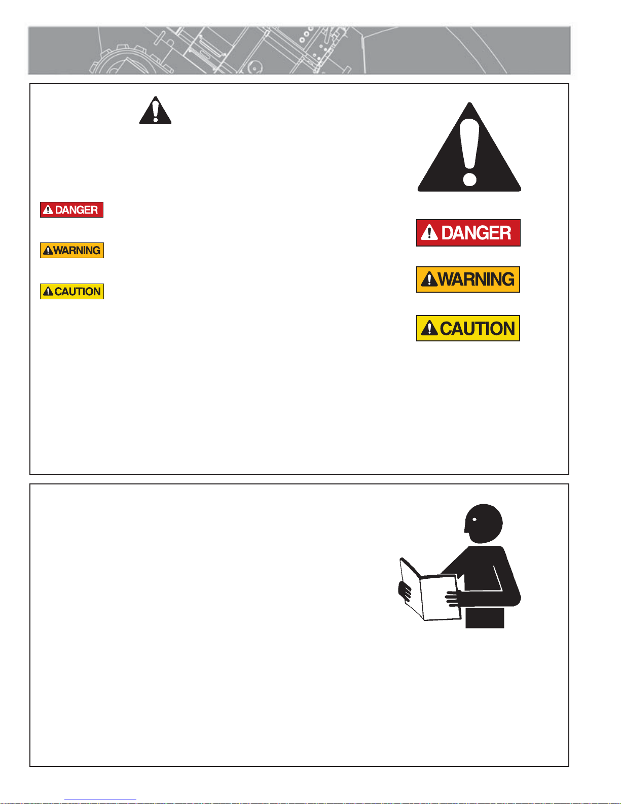
Safety Alerts
This hazard alert sign appears in this manual.
When you see this sign, carefully read what it says.
YOUR SAFETY IS AT STAKE.
You will see the hazard alert sign with these words:
DANGER, WARNING, and CAUTION.
Indicates an imminently hazardous
situation which, if not avoided, will
result in death or serious injury.
Indicates a potentially hazardous
situation which, if not avoided, could
result in death or serious injury.
Indicates a hazardous situation which,
if not avoided, may result in minor or
moderate injury.
In this manual you should look for two other words:
NOTICE and IMPORTANT.
NOTICE: can keep you from doing something that might
damage the machine or someone's property. It may also
be used to alert against unsafe practices.
IMPORTANT: can help you do a better job or make your
job easier in some way.
WR00051-11-30-92
TX00030-12-1-92
Read and Understand
Do not operate this equipment until you have carefully read, and
understand all the sections of this manual, and all other equipment
manuals that will be used with it.
Your safety and the safety of others depends upon care and
judgment in the operation of this equipment.
Follow all applicable federal, state, local, and industry specific
regulations.
McElroy Manufacturing, Inc. cannot anticipate every possible
circumstance that might involve a potential hazard. The warnings
in this manual and on the machine are therefore not all inclusive.
You must satisfy yourself that a procedure, tool, work method, or
operating technique is safe for you and others. You should also
ensure that the machine will not be damaged or made unsafe by
the method of operation or maintenance you choose.
TX02946-4-15-09
WR00052-12-1-92
1 - 1
Fusion Equipment Safety
FUEL
General Safety
Safety is important. Report anything unusual that you notice during
set up or operation.
LISTEN for thumps, bumps, rattles, squeals, air leaks, or unusual
sounds.
SMELL odors like burning insulation, hot metal, burning rubber, hot
oil, or natural gas.
FEEL any changes in the way the equipment operates.
SEE problems with wiring and cables, hydraulic connections, or other
equipment.
REPORT anything you see, feel, smell, or hear that is different from
what you expect, or that you think may be unsafe.
TX00114-4-22-93
SAFE1ST-12-22-92
Wear Safety Equipment
Wear a hard hat, safety shoes, safety glasses, and other
applicable personal protective equipment.
Remove jewelry and rings, and do not wear loose-fitting clothing
or long hair that could catch on controls or moving machinery.
TX00032-4-7-93
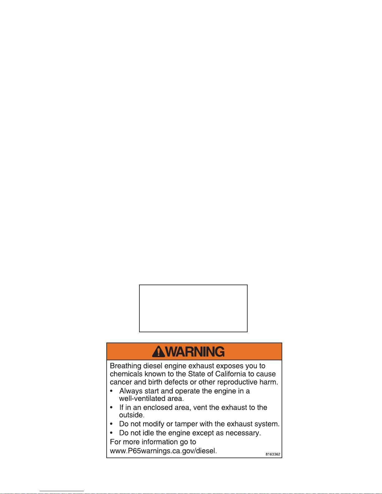
Fuel Handling
Gasoline and diesel fuel are extremely flammable
and their vapors will explode if ignited.
Do not fill the fuel tank while the engine is hot or running, as
spilled fuel could ignite.
Refuel in a well ventilated area. Do not smoke or allow flames or
sparks in the area where the engine is refueled, or where gasoline
is stored.
Do not start the engine near spilled fuel. Wipe up spills
immediately.
Maker sure the fuel tank cap is closed and properly secured.
NOTICE: Avoid repeated or prolonged contact with skin or
breathing of vapor.
WR00053-12-2-92
CD00365-2-19-97
TX00953-3-30-11
1 - 2
Fusion Equipment Safety
Units With Engines
Combustion engines can cause explosions when
operated in an explosive atmosphere. Do not
operate gas or diesel powered machines in an
explosive atmosphere.
When operating in an explosive atmosphere, keep engine and
chassis in a safe area by using hydraulic extension hoses.
Help prevent fires by keeping machine clean of accumulated
trash, debris and facer shavings.
TX04466-05-05-14
Carbon Monoxide
Engine exhaust gases contain poisonous carbon
monoxide. Carbon monoxide can cause severe
nausea, fainting and death. Avoid inhaling
exhaust fumes and never run the engine in a
closed or confined area.
WR00080-4-12-93
WR00093-5-14-96
TX00954-5-14-96
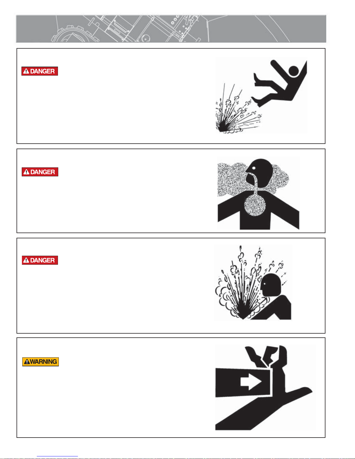
Heater is Not Explosion Proof
This heater is not explosion proof. Operation
of heater in an explosive atmosphere without
necessary safety precautions will result in
serious injury or death.
When operating in an explosive atmosphere, the heater should
be brought up to temperature in a safe environment, then
unplugged before entering the explosive atmosphere for fusion.
TX04467-03-24-14
Crush Points
Hydraulically operated equipment is operated
under pressure. Anything caught in the machine
will be crushed. Keep fingers, feet, arms, legs,
and head out of the machine while operated.
WR00034-11-30-92
WR00012-12-4-92
TX03004-8-11-09
1 - 3
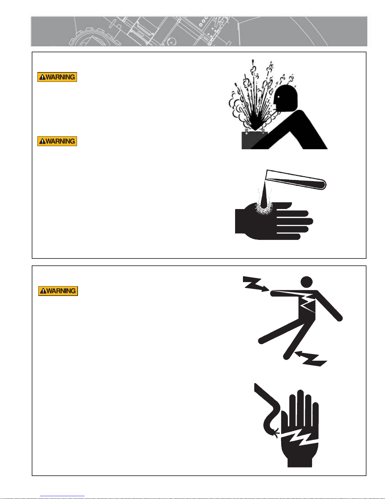
Battery
Fusion Equipment Safety
Do not expose the battery to flames or electrical
sparks. Hydrogen gas generated by battery action is
explosive. Blindness or serious injury can result from
an exploding battery.
Do not allow battery fluid to contact your skin, eyes,
fabrics, or painted surfaces. Sulfuric acid can cause
burns. After touching a batter or battery cap, do not
touch or rub your eyes.
Eye Contact: Flush eyes with large amounts of water
for at least 15 minutes. Seek immediate medical
attention if eyes have been exposed directly to acid.
Skin Contact: Flush affected area(s) with large
amounts of water using deluge emergency shower,
if available, shower for at least 15 minutes. Remove
contaminated clothing. If symptoms persist, seek
medical attention.
CD00176-9-14-95
CD00177-9-14-95
TX00650-3-7-11
Electrical Safety
Always ensure equipment is properly grounded.
It is important to remember that you are working
in a wet environment with electrical devices.
Proper ground connections help to minimize the
chances of an electric shock.
Frequently inspect electrical cords and unit for damage. Have
damaged components replaced and service performed by a
qualified electrician.
NOTICE: Always connect units to the proper power source as
listed on the unit, or in the owner's manual.
NOTICE: Disconnect the battery before attempting any
maintenance or adjustment.
WR00055-4-7-93WR00025-11-30-92
TX04468-10-24-12
1 - 4
Fusion Equipment Safety
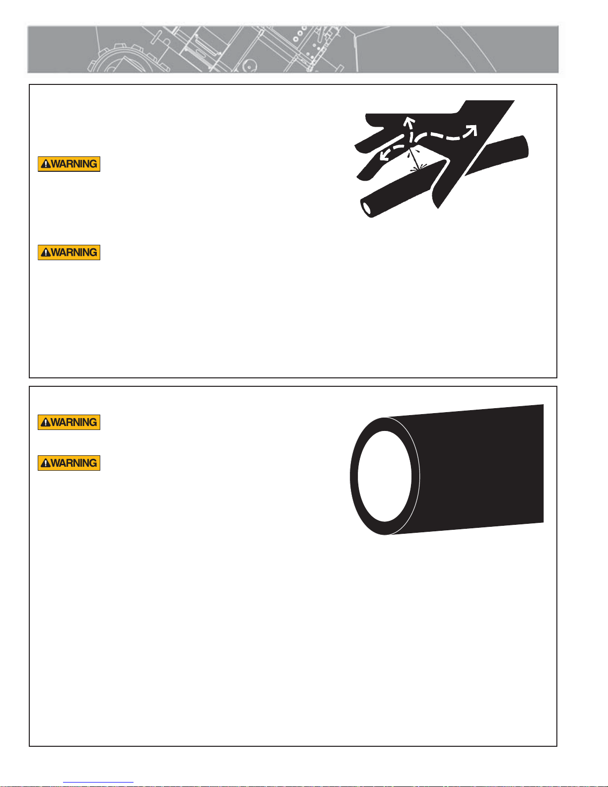
Units With Hydraulics
It is important to remember that a sudden hydraulic oil leak
can cause serious injury, or even be fatal if the pressure is high
enough.
Escaping fluid under pressure can penetrate the
skin causing serious injury. Keep hands and
body away from pinholes which eject fluid under
pressure. Use a piece of cardboard or paper to
search for leaks. If any fluid is injected into the
skin, it must be immediately removed by a doctor
familiar with this type of injury.
Unwanted movement of the machine could result
in serious injury or damage to machine. Unwanted
movement of the machine may take place if switches
do not match machine state when the machine power
is turned on.
NOTICE: Wear safety glasses, and keep face clear of area when
bleeding air from hydraulic system to avoid spraying oil into eyes.
WR00078-4-8-93
TX03007-10-12-10
Pipe Handling Safety
Do not position yourself under supported or
raised pipe. Pipe is heavy and could result in
serious injury or death.
Pipe that is bent can store a great amount of
energy. Do not bend and force the pipe into the
machine. A bent pipe with stored energy could
cause serious injury or death when that energy is
released.
It is recommended that the pipe is always be held securely by
either being clamped securely in the fusion machine jaws or
attached to the lifting device.
Keep persons that are not involved in handling pipe away from
handling operations. When the pipe and handling equipment are in
motion, all persons involved in handling pipe should be able to see
all other persons at all times. If any handling person is not in sight,
immediately stop moving equipment and pipe and locate that person.
Do not continue until all persons are accounted for and in sight.
NOTICE: Do not leave machine unattended while the Power Pack is
running. When not operating the machine, turn off the Power Pack. This
will prevent accidental or unintentional movement of the machine.
Never push, roll, dump or drop pipe lengths, bundles or coils off the
truck, off handling equipment or into a trench. Always use appropriate
equipment to lift, move and lower the pipe.
WR00097-4-17-13
TX04586-4-17-13
1 - 5

Fusion Equipment Safety
Facer Blades Are Sharp
Facer blades are sharp and can cut. Never
attempt to remove shavings while the facer is
running, or is in the facing position between the
jaws. Use care when operating the facer, and
when handling the unit.
NOTICE: Disconnect power from the facer, and remove the facer
blades before attempting any maintenance or adjustment.
NOTICE: Never extend the blade beyond the inner or outer
circumference of the facer.
TX02378-1-24-05
Keep Machine Away From Edge of Ditch
Heavy equipment too close to a ditch can
cause the walls of the ditch to cave-in. Keep the
machine far enough away from the edge of the
ditch to prevent injury to personnel and damage
to the equipment from a cave-in.
WR00073-4-6-93
CD00408-12-31-97
TX01447-3-30-11
Operating Fusion Machine
Place fusion machine on as level ground as possible.
If it is necessary to operate machine on unlevel grade, chock
the tracks and block the unit to make it as stable as possible.
Some unstable conditions may be ice, snow, mud and loose
gravel.
Operating machine on a grade steeper than
30% could cause the machine to tip over.
Never operate the machine on a grade
steeper than 30 % (A 3 foot elevation change
in 10 feet). Always operate fusion machine
from the highest level, on an unlevel grade.
Failure to do so could result in serious injury
or death.
CD00402B-12-30-97
TX01902-3-30-11
1 - 6
Fusion Equipment Safety
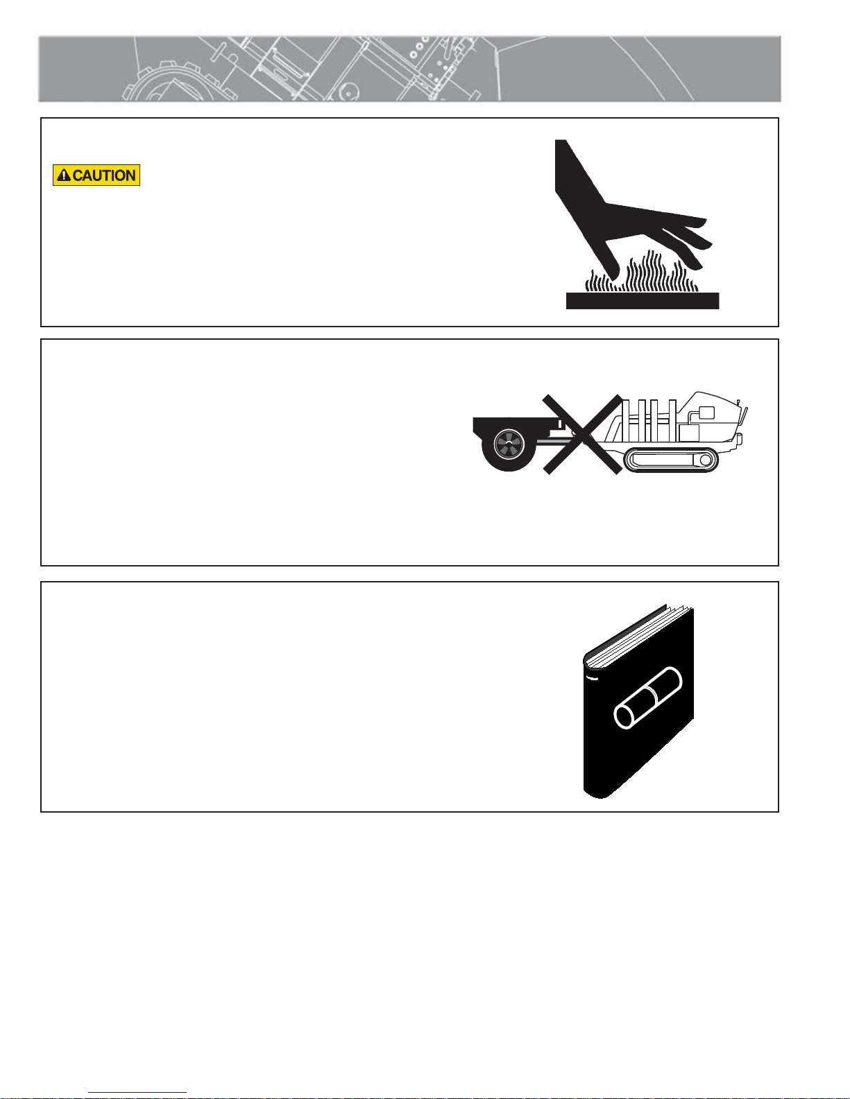
Heater Is Hot
The heater is hot and will burn clothing and skin.
Keep the heater in its insulated heater shroud
when not in use, and use care when heating the
pipe.
NOTICE: Use only a clean non-synthetic cloth to clean the heater
plates.
TX04244-10-12-10
Do Not Attempt to Tow Fusion Machine
NOTICE: The machine is not designed for towing. Attempting to
tow the machine can result in machine damage. Always transport
the machine by flat bed truck or similar means, and make sure
that unit is properly secured.
WR00030-2-10-93
CD00401-12-30-97
TX01888-3-30-11
Fusion Procedures
Obtain a copy of the pipe manufacturer's procedures or
appropriate joining standard for the pipe being fused. Follow the
procedure carefully, and adhere to all specified parameters.
NOTICE: Failure to follow pipe manufacturer's procedure could result in a
bad joint. Always follow pipe manufacturer's procedures.
TX04469-10-24-12
WR00079-2-7-96
1 - 7
Overview
Theory of Heat Fusion
The principle of heat fusion is to heat two surfaces to a
designated temperature, and then fuse them together by
application of force. This pressure causes flow of the melted
materials, which causes mixing and thus fusion. When the
polyethylene material is heated, the molecular structure is
transformed from a crystalline state into an amorphous condition.
When fusion pressure is applied, the molecules from each
polyethylene part mix. As the joint cools, the molecules return to
their crystalline form, the original interfaces are gone, and the
fitting and pipe have become one homogeneous unit. A strong,
fully leak tight connection is the result.
The principal operations include:
Clamping The pipe pieces held axially to allow all subsequent
operations to take place.
Facing The pipe ends must be faced to establish clean,
parallel mating surfaces perpendicular to the
centerline of the pipes.
Aligning The pipe ends must be aligned with each other to
minimize mismatch or high-low of the pipe walls.
Heating A melt pattern that penetrates into the pipe must be
formed around both pipe ends.
Joining The melt patterns must be joined with a specified
force. The force must be constant around the interface
area.
Holding The molten joint must be held immobile with a
specified force until adequately cooled.
Inspecting Visually examine the entire circumference of the joint
for compliance with standards established by your
company, customer, industry, federal, state, or local
regulations.
PH00363B-1-4-96
TX02476-04-28-14
2 - 1
Overview
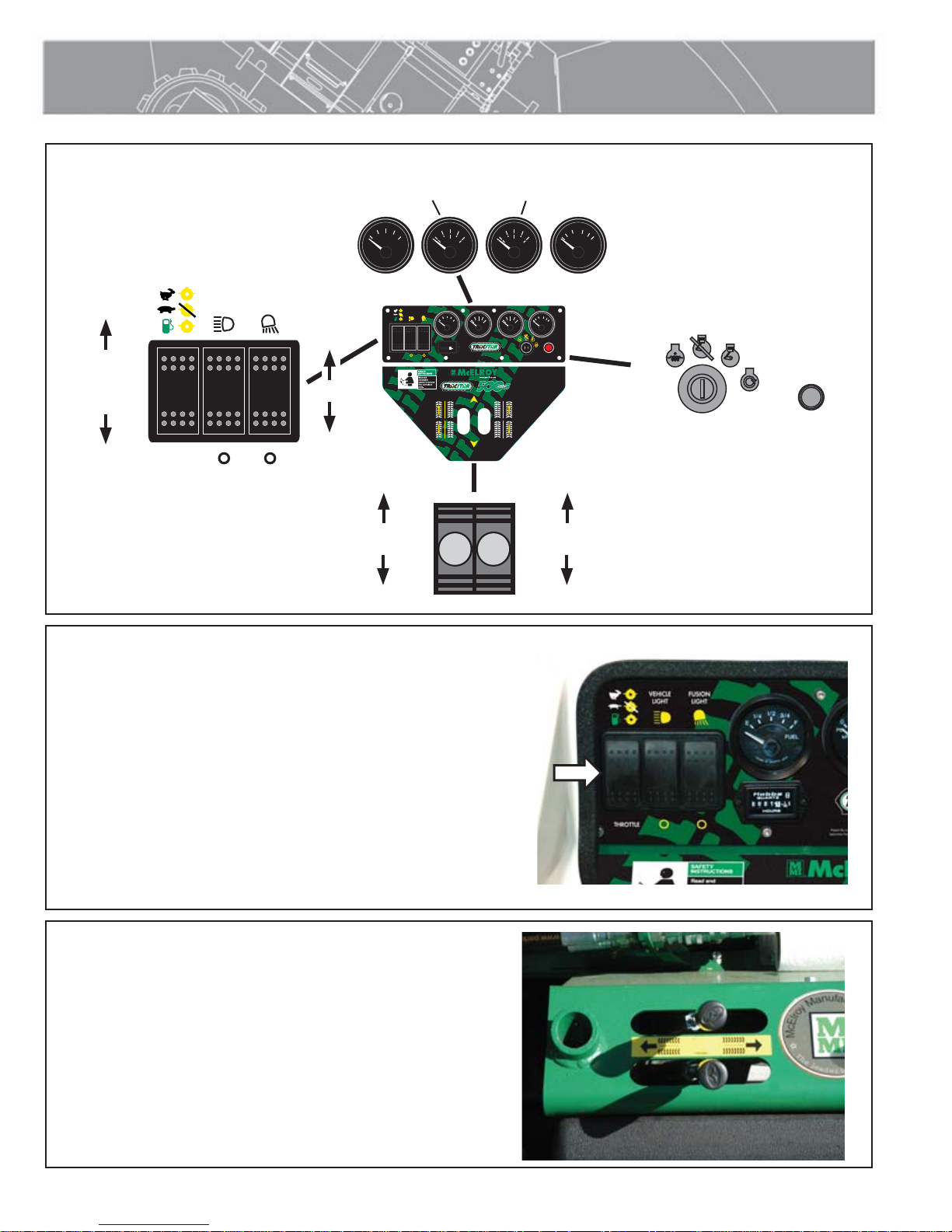
TracStar® 500 series 3 Console
FUEL
LIGHT
GAUGE
WORK
LIGHT
ON
LIGHTS
OFF
BACKWARD
HIGH
(Power for
heater)
LOW
(No power
for heater)
AUTO
(Cycles
engine
throttle on
demand)
HEADLIGHTS
VEHICLE
THROTTLE
LIGHT
FUSION
ENGINE OIL
PRESSURE
1/2
1/4
3/4
E
F
FUEL VOLTS
VEHICLE
LIGHT
THROTTLE
FORWARD
LEFT TRACK
CONTROL
50
25
75
100
0
350
PSI
0
700
kPa
FUSION
LIGHT
1/2
1/4
25
3/4
E
0
F
PSI
0
FUEL VOLTS
kPa
QUARTZ
1
10
1
0001
HOURS
Patent No.'s 5,814,182 - 6,212,748 - 6,212,747 - 6,021,832
Patent No.'s 5,814,182 - 6,212,748 - 6,212,747 - 6,021,832
Japanese Patent No. 4285806 - OTHER PATENTS PENDING
®
FORWARD
BACKWARD
COOLANT
TEMPERATURE
180
210
150
250100
80
°F
40
120
°C
50
180
14
12
210
75
150
10
100
350
700
®
16
250100
18
8
80
°F
40
120
°C
FORWARD
RIGHT TRACK
CONTROL
BACKWARD
14
12
10
16
18
8
T5055102
T5017103
VOLT
METER
PREHEAT
PLUG
CD00407e-10-8-12
OFF
RUN
START
IGNITION PREHEAT
PLUG
LIGHT
Auto Throttle
Pressing the throttle switch on the dashboard to the bottom position
turns on the auto throttle setting.
The auto throttle setting is used to vary the speed of the engine
depending on the load needs of the machine. The machine will use
high speed while facing, moving the carriage, or when the heater
controller cycles on.
Auto throttle will reduce the amount of noise and fuel usage.
TX04470-10-24-12
Alternate Drive Controls
Alternate track drive controls are located on the operator side
of the machine. Each lever controls one track. Both levers must
be moved together to go forward or backward in a straight line.
Moving levers in opposite directions makes the machine turn
sharply.
PH04789-10-8-12
PH04729-10-1-12
TX02002-4-24-02
2 - 2
Overview
Pipe Lift Controls
The pipe lift controls are located on the operator side of the
machine to the right of the alternate drive controls. Moving the
right lever up and down moves the rear pipe lift up and down.
Moving the left lever up and down moves the forward pipe lift up
and down.
TX02003-4-24-02
Carriage Assembly
The carriage assembly consists of two fixed jaws and two
hydraulically operated movable jaws. The carriage assembly
can be used in a 4 jaw and 3 jaw configurations. The 4 jaw
configuration includes the use of the indexer for the heater and
facer. The 4th jaw can be removed on the 4 jaw configuration for
fusions of ells and tees.
The 3 jaw configuration is removed from the 4 jaw skid and does
not use the indexer for the heater and facer. The 3 jaw is a compact
fusion configuration for use in close quarters where space is
limited.
The carriage assembly can be removed from the machine for
remote operation. An optional hydraulic extension and electric
cable extension kit is required when using the carriage remotely.
TX04472-10-24-12
PH04730-10-1-12
PH04739-10-24-12
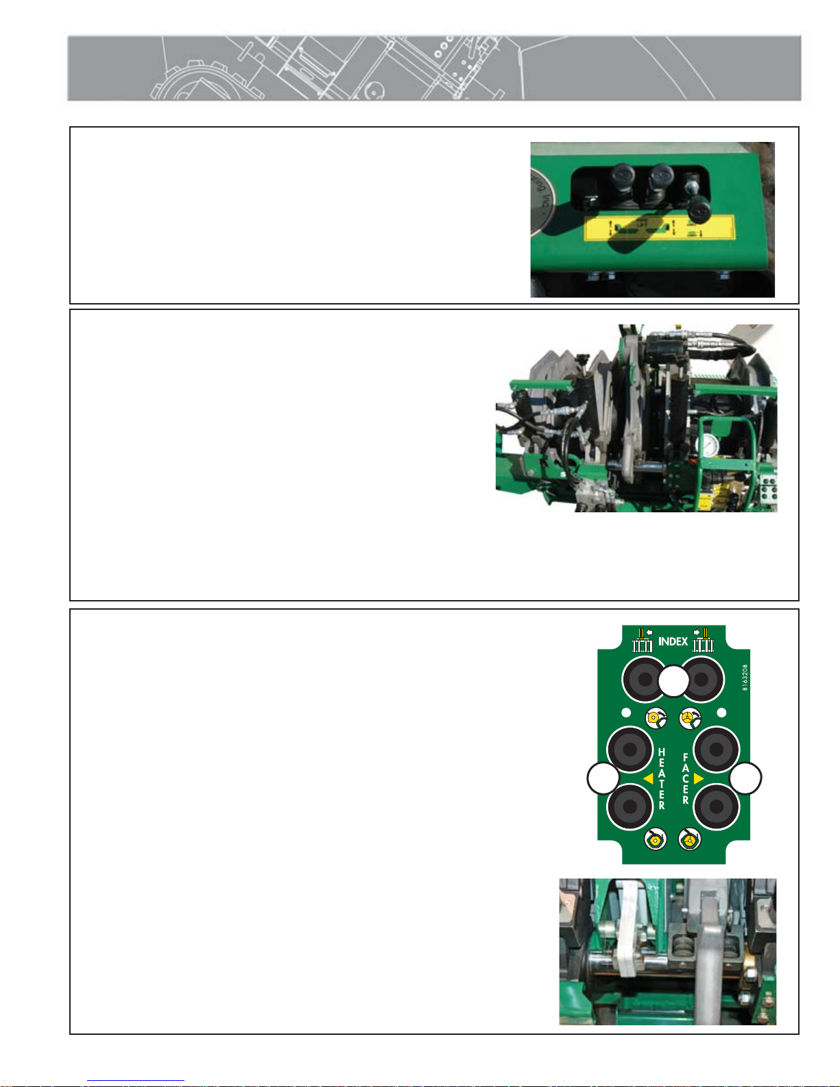
Indexer Controls
The indexer controls are located on the movable jaws of the
carriage at the operator position.
1 Controls the movement of the indexer to the left and right.
2 Controls the movement of the heater, moving the heater in and out of the
carriage.
3 Controls the movement of the facer, moving the facer in and out of the
carriage.
During transport, the heater, heater shroud, and facer can be
rotated into the carriage and the carriage closed on all three
capturing them between the jaws keeping them secure during the
moving of the machine or transporting the machine.
TX04474-10-24-12
1
CD01037-10-1-12
2 3
PH04814-10-24-12
2 - 3
Overview
Inlet Fans
Inlet fans are used to draw cooler air from the outside of the
machine to the generator compartment.
NOTICE: Never obstruct the fans. Allow enough area for air to
circulate into the machine. Restricting air to the fans could cause
components to overheat and fail.
TX04990-04-27-16
Facer
The facer is a McElroy rotating planer-block design. The blade
holders each contain three cutter blades. The block rotates on ball
bearings and is chain driven (enclosed in lubricant) by a hydraulic
motor. The facer is removable for in-ditch operation and features a
lifting point for lifting the facer in and out of the ditch.
NOTICE: Never extend the blade beyond the inner or outer
circumference of the facer.
TX04473-10-24-12
PH04741-10-8-12 PH05507-04-27-16
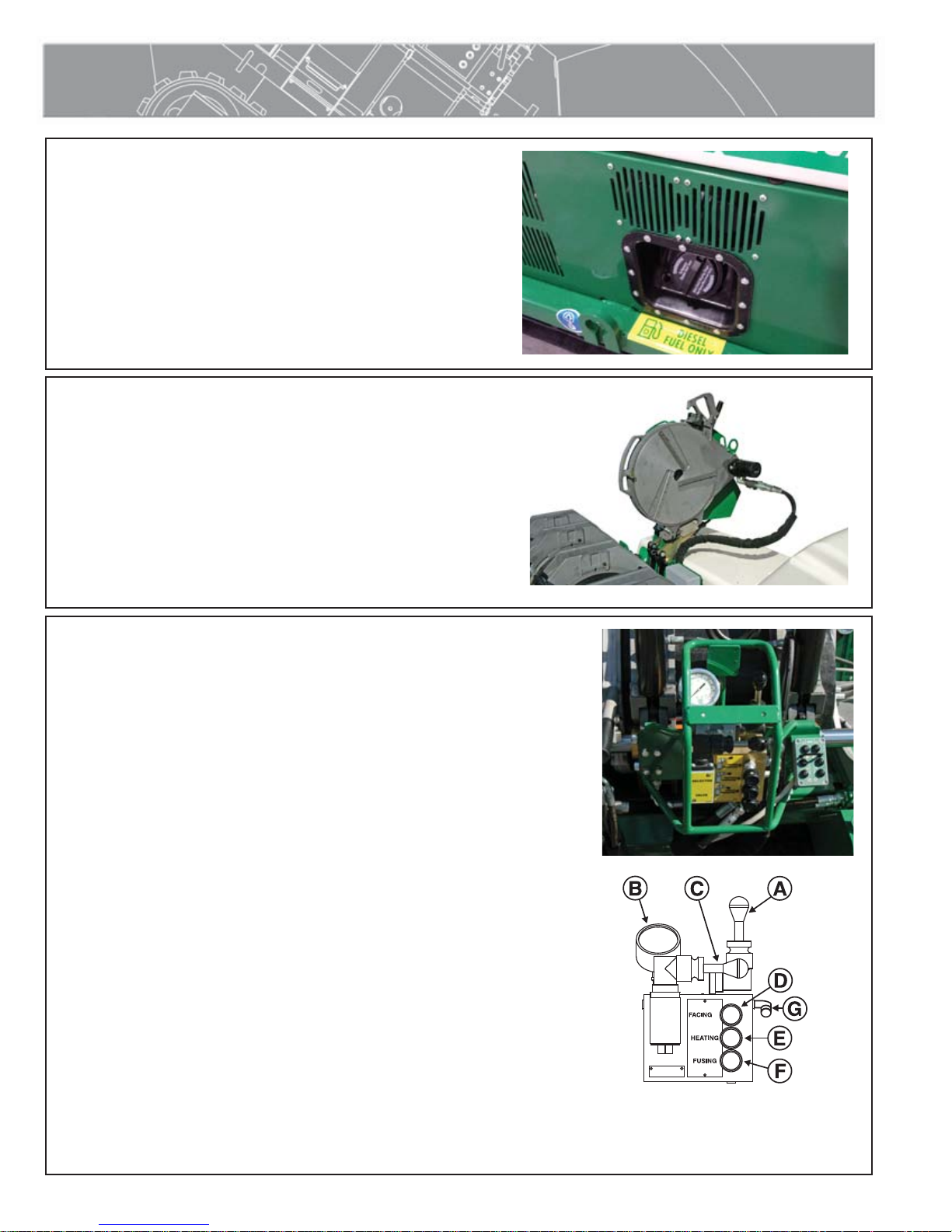
Hydraulic Manifold Block
Mounted on this block are a carriage directional control valve, a
pressure reducing selector valve, three pressure reducing valves,
and a 3000 psi gauge.
A) The carriage control valve, mounted on the top of the manifold,
determines whether the carriage is moving left, right, or is in
neutral.
B) A 3000 psi gauge is mounted on top of the manifold.
C) The selector valve, mounted on the front of the manifold, selects
a reduced pressure from one of the pressure reducing valves.
Each pressure reducing valve is labeled with a different function:
D) The top valve adjusts facing pressure to a maximum of 400 psi.
E) The middle valve adjusts heating pressure to a maximum of
400 psi.
F) The bottom valve adjusts fusion pressure to a maximum of 2300
psi, which is the set system pressure.
G) DataLogger port
PH04731-10-1-12
CD00138H-1-12-11
TX04541-10-24-12
2 - 4

Overview
Heater
The heater is equipped with butt fusion heater plates, coated with
an antistick coating.
This heater is not explosion proof. Operation
of heater in an explosive atmosphere without
necessary safety precautions will result in serious
injury or death.
The heater cord plugs into a military type receptacle on the heater
arm and electrical box. Tighten coupling nut after plugging into the
receptacle.
PH04796-10-15-12
Before the heater is used, the heater must be rotated all the way out
of the carriage and the heater shroud pin removed. This will allow
the heater to separate from the heater shroud.
When the machine is ready to be stored or transported, rotate the
heater out of the carriage and hold the heater shroud handle and
insert the pin to capture the heater in the heater shroud. The heater
and heater shroud are now connected and can be rotated into the
carriage together.
When needed, the heater can be removed from its indexer mounted
pivot arm, for in-ditch operation. The heater has a lifting point on
the top of the heater and a stripper bar is available for in-ditch
operation.
The optional extension kit as well as the optional heater stand is
needed for in-ditch heater operation.
GFCI Operation and Testing
1. Press RESET button. The GREEN “power” LED should be ON.
2. Press TEST button: GREEN LED should turn OFF, RED LED should
start BLINKING. Circuit breaker should trip to OFF position.
3. If sensing module LEDs do not trip. DO NOT USE THIS DEVICE.
Consult a qualified electrician for assistance.
4. Press RESET button: RED LED should turn OFF and GREEN LED
should turn ON.
5. MANUALLY RESET circuit breaker to ON position to restore circuit
power.
Do not use this device if it fails any portion of
the above test. If the device fails, a possible shock
hazard could occur leading to serious injury or
death. Consult a qualified electrician for repair or
replacement.
Test the GFCI module regularly in accordance with local rules and
regulations
TX04475-05-05-14
PH04732-10-1-12
PH04813-10-24-12
PH04810-10-24-12
2 - 5

Overview
Diesel Engine
Read the operating and maintenance instructions for the engine
before operating.
There is a key ignition on the console that shows the preheat, start,
run and off positions.
TX01465-2-10-98
Hydraulic Fluid Reservoir
The hydraulic fluid reservoir is located under the front hood of the
machine. The fluid level sight gauge is located on the front of the
reservoir. Proper fluid level is indicated on the sight gauge.
PH04790-10-24-12PH04027-3-2-10
PH01251-1-29-98
TX01467-05-05-14
Filter
This machine is equipped with a 10 Micron filter on the return
side of the circuit.
TX01496-3-3-98
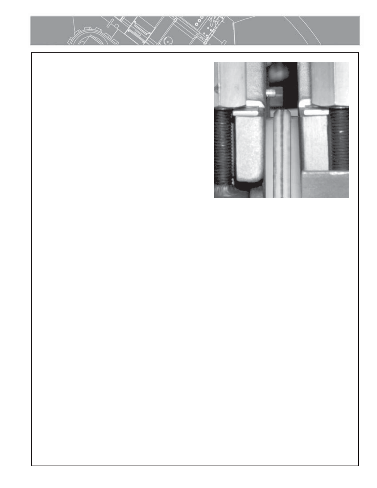
Hydraulic Clamping
Hydraulic clamping cylinders apply force to the jaws to clamp the
pipe. Both inner cylinders have knobs that can adjust the stroke of
the cylinder for Hi/Lo adjustment.
PH02000-1-15-01
TX04476-10-24-12
2 - 6

Operation
Read Before Operating
Before operating this machine, please read this manual
thoroughly and keep a copy available for future reference.
Return manual to the protective storage box when not in use. This
manual is to be considered part of your machine.
TX00401-9-15-94
Check Hydraulic Fluid Level
Check fluid level in sight gauge on reservoir and add fluid if
necessary.
Refer to the "Hydraulic Fluids" section of this manual for hydraulic
fluid recommendations.
Stop-12-28-95
PH01251-2-2-98
TX01450-05-05-14
Diesel Engine
Read the operating and maintenance instructions for the engine
before operating.
The key ignition has four positions. Preheat, off, run and start.
NOTICE: Switch the engine to slow speed before starting.
For cold weather starting, turn switch to preheat for no longer than 10
seconds. Never use starting fluid.
Turn the key and start the engine.
Confirm that all gauges read correctly.
Turn the key to OFF to stop the engine.
PH04790-10-8-12
TX02377-1-10-05
3 - 1

Operation
Moving Machine Into Position
Make sure all personnel are safely clear of the machine
before moving.
Move both track control levers forward to go in a straight
line. Release the levers to stop. Moving just the right track
forward turns the machine to the left. Moving just the left
track forward turns the machine to the right. There are
alternate track controls on the left side of the machine.
The track speed valve (A) is used to switch between low
speed/high torque and high speed/low torque. The machine
will not have torque available to turn in all conditions in high
speed.
PH02290-4-17-02
TX04477-10-24-12
Prepare Heater
Install butt fusion heater plates.
NOTICE: Non-coated heaters should never be used without butt
fusion heater plates installed. Refer to the "Maintenance" section
of this manual for installation procedure.
Heater is not explosion proof. Operation of
heater in an explosive atmosphere without
necessary safety precautions will result in serious
injury or death.
If operating in an explosive atmosphere, heater should be brought
up to temperature in a safe environment, then unplugged before
entering the explosive atmosphere for fusion.
Ensure the heater cables are connected and switch the throttle to
High or Auto.
PH04729-10-1-12
PH04730-10-1-12
A
PH04796-10-1-12
Refer to the section "Adjusting Heater Temperature" in the
Maintenance section of this manual for instructions on setting the
heater temperature.
TX04531-05-05-14
PH04789-10-8-12
3 - 2

Operation
Install Clamping Inserts
Select and install appropriate clamping inserts for the pipe that is
being fused.
TX00368-9-15-94
Set up Pipe Supports
Set up pipe stands and adjust height so the pipe is in line with the
jaws.
PH02283- 4-2-02
PH01264-2-12-98
X00367-9-15-94
Loading Pipe into Machine
Clean the inside and outside of pipe ends that are to be fused.
Open the upper jaws and insert pipe in each pair of jaws with
applicable inserts installed.
Let the pipe ends protrude more than 1” past the face of the
jaws.
PH04734-10-1-12
TX01094-8-20-96
3 - 3

Operation
Positioning Pipe into Machine
Swing the facer into place. Move the carriage toward the fixed
jaw, while watching the gap at each end of the facer guide rod
brackets. When the pipe is in contact with the facer, this gap
indicates the amount of material that will be trimmed from the pipe
end. Assure sufficient material will be removed for a complete face
off.
PH04735-10-24-12
TX04479-10-24-12
Hydraulic Clamping
The controls are located on the end of the inner fixed jaw. The left knob
(A) opens/closes the fixed jaws and the right knob (B) opens/closes the
movable jaws.
To unclamp the jaws:
With your free hand, hold the tie bar between two cylinders.
Rotate the valve knob up to unclamp.
Pull the tie bar towards operator until the cylinders come to rest.
To clamp the jaws:
Push the cylinder tie bar toward the jaws until cylinders are vertical.
Rotate the valve knob down to clamp.
Hi/Lo adjustment:
Unclamp the jaw slightly and return the clamping control to the neutral
position. Make adjustments to the Hi/Lo by turning the knob on top of
the cylinder and then reclamp the jaw.
Prior to starting the machine, always ensure that the
hydraulic clamping directional valves are both in the
center (neutral) position to eliminate undesired clamp
cylinder movement during startup.
A
B
PH04058-3-2-10
PH04059-3-2-10
TX04480-10-24-12
3 - 4

Operation
Begin Facing
Turn facer on by opening valve on top of the facer.
Move the selector valve on the hydraulic manifold block to the
top (facing pressure) position.
The facing pressure should be set as low as possible while still facing
pipe. Excessive facing pressure can damage the facer. It may be
necessary to adjust the carriage pressure.
Facer blades are sharp and can cut. Never
attempt to remove shavings while the facer is
running, or is in the facing position between the
jaws. Use care when operating the facer, and
when handling the unit.
Activate the carriage control valve and move the carriage to the
left to begin facing. Continue to face the pipe until the rest buttons
on the jaws bottom out on the facer rest buttons.
PH04735-10-2-12
PH04736-10-2-12
TX04261-3-30-11
After Facing
Turn facer motor off. Move carriage all the way to the right.
Center the facer in between the pipe ends to avoid dragging facer
stops on the pipe ends. Swing facer to the out position. Clean
shavings out of pipe ends and from between the jaws. Do not
touch faced pipe ends.
PH04741-10-24-12
TX04262-3-30-11
3 - 5

Operation
Check Alignment
Move carriage to the left at facing pressure, until pipe ends contact.
Look across the top surface of pipe ends to check alignment. If there is
a noticeable step across the joint, adjustments must be made.
Hydraulically operated equipment is operated under
pressure. Anything caught in the machine will be
crushed. Keep fingers, feet, arms, legs, and head out
of the machine while operated.
Ensure there is no unacceptable gap between the pipe ends. If there is
an unacceptable gap, return to Loading Pipe into Machine.
If pipe is not lined up, make a HI/LO adjustment to the jaw of the high
side.
Hi/Lo adjustment:
Unclamp the jaw slightly and return the clamping control to the neutral
position. Make adjustments to the Hi/Lo by turning the knob on top of
the cylinder and then reclamp the jaw.
IMPORTANT: Always tighten the side that is higher, never loosen the
low side.
Repeat adjustment until pipe is aligned.
NOTICE: When clamping, do not over-adjust the clamping force
because machine damage can result. Check to see if there is space
between the upper and lower jaws. If the two jaws are touching, do
not continue to tighten.
Over-adjustment may cause thin-walled pipe to compress affecting the
ovality of the pipe
TX04482-10-24-12
PH04737-10 -2-12
PH04742-10-8-12
Determine Drag Pressure
Drag pressure should be determined using the following
procedure:
Move the carriage so that the faced pipe ends are
approximately 2" apart.
Shift the carriage control valve to the middle (neutral) position.
Select the heating mode, and adjust the middle pressure
reducing valve to its lowest pressure by turning the valve
counterclockwise.
Shift the carriage control valve to the left.
Gradually increase the pressure by turning the valve clockwise.
Increase the pressure until the carriage moves.
Quickly reduce the heating pressure valve counterclockwise
until the carriage is just barely moving.
Record this actual drag pressure.
TX03023-8-19-09
3 - 6
B
A
C
D
A - Carriage Control Valve
B - Pressure Gauge
C - Pressure Selector Valve
D - Pressure Reducing Valves (3)
PH01924-11-15-00

Operation
Set Fusion Pressure
With the selector valve in the down position, the fusion pressure
can be set.
The theoretical fusion pressure can be calculated using the
enclosed fusion pressure calculator. Always add drag pressure to
the theoretical fusion pressure.
Gauge (Fusion) Pressure = Theoretical Fusion Pressure + Drag
Pressure
TX03024-10-19-10
Check for Slippage
Bring the two sections of pipe together under fusion pressure to
make sure they don’t slip in the jaws.
If slippage occurs, return to Loading Pipe into Machine.
PH04004-8-25-09
TX00971-12-7-10
Position Carriage for Heater Insertion
Move the carriage to open a gap large enough to insert the
heater.
PH04737-10 -8-12
PH04785-10-8-12
TX01462-2-9-98
3 - 7

Operation
Check Heater Temperature
NOTICE: Incorrect heating temperature can result in
questionable fusion joints. Check heater plates
periodically with a pyrometer and make necessary
adjustments.
Check heater surface temperature.
Refer to the pipe manufacturer's recommendations or appropriate
joining standard for proper heater temperature.
TX04536-10-24-12
Inserting Heater
Heater is not explosion proof. This unit is not
explosion proof. Operation of heater in an
explosive atmosphere without necessary safety
precautions will result in serious injury or death.
WR00077-4-16-93
PH04738-10-2-12
If operating in an explosive atmosphere, heater
should be brought up to temperature in a safe
environment, then unplugged before entering the
explosive atmosphere for fusion.
Use a clean non-synthetic cloth to clean the butt fusion heater plate
surfaces.
Verify heater temperature by noting the reading on the dial
thermometer.
Insert heater between the pipe ends.
TX04537-05-05-14
PH04803-10-24-12
3 - 8

Heat Pipe
Operation
Shift the selector valve (A) to the center position, and set the heating
pressure (if required). If heating pressure is not required, set the
pressure reducing valve (B) at its lowest setting, or the drag pressure,
whichever is higher.
Shift the selector valve (A) to the fusion position and move the
carriage control valve (C) to the left to bring pipe ends in contact
with the heater. Move selector valve (A) to middle (heating mode)
position. If heater pressure is not required by pipe manufacturer or
joining standard, or opposing forces are not great enough to move the
carriage away from the heater, shift the carriage control valve to
neutral.
IMPORTANT: Always shift into the heating mode before returning
carriage valve to neutral.
Follow the pipe manufacturer's suggested heating and soaking
procedure or joining standard.
TX04264-3-30-11
C
PH04731-10-24-12
A
B
PH04804-10-24-12
Fusing the Pipe
NOTICE: Failure to follow the pipe manufacturer's heating time,
pressure and cooling time may result in a bad joint.
After following the heating procedure, verify carriage control valve is
in neutral and move selector valve down, to fusion position.
Move the carriage to the right just enough to remove the heater.
Quickly remove the heater.
Quickly inspect pipe ends for appropriate melt.
When heater is clear of the jaws, quickly move the carriage to the
left and bring the pipe ends together using the pipe manufacturer’s
recommended pressure.
Allow joint to cool under pressure according to pipe manufacturer’s
recommendations or appropriate joining standard.
Visually examine the entire circumference of the joint for compliance
with standards established by your company, customer, industry,
federal, state, or local regulations.
TX04265-3-30-11
PH04805-10-24-12
3 - 9

Operation
Opening Movable Jaws
After the joint has cooled for the pipe manufacturer's
recommended time, shift the carriage control to the neutral
position.
Unclamp the clamp cylinders, and open carriage far enough to
open the jaw nearest the facer.
Open the movable jaws.
TX04486-10-24-12
Opening Fixed Jaws
Open the fixed jaws.
PH04806-10-24-10-2
PH04807-10-24-12
TX00381-9-16-94
Raise Pipe
Raise the joined pipe using the hydraulic pipe lift.
TX00818-12-21-95
Position Pipe for Next Joint
Move the fusion machine to end of pipe, or pull the pipe through
the jaws until the end of the pipe is protruding more than 1" past
the jaw face of the fixed jaw.
PH02301-4-17-02
PH04808-10-24-12
TX01091-8-20-96
3 - 10

Operation
Install Next Piece of Pipe
Insert a new piece of pipe in movable jaws and repeat all
previous procedures.
TX00384-10-12-95
PH04809-10-24-12
3 - 11

Special Operations - In Ditch
Overview
The carriage may be removed and hoisted into a ditch. The 4
jaw carriage can be used with heater and facer attached to the
indexer or if needed, a more compact 3 jaw carriage. Using the
3 jaw carriage requires lifting equipment to hoist the heater and
facer from overhead and will require an optional 3 jaw in-ditch kit
containing heater and facer stands, stripper bars for heater, and
guide rod bracket for facer. An optional hose and cable extension
kit is required for both 3 jaw and 4 jaw in-ditch operation.
NOTICE: Turn ignition key to off position before doing anything
else.
TX04487-10-24-12
Remove Hydraulic Hoses and Cables
PH04790-10-24-12
Disconnect the hydraulic hoses, electrical cables, and heater
power cable from the carriage.
NOTICE: All connections must be disconnected or damage will
result when removing the carriage.
PH04766-10-8-12PH04810-10-8-12
TX04488-10-24-12
4 - 1

Special Operations - In Ditch
Remove 4 Jaw Carriage
Remove the carriage pin at the front of the machine.
Slide the carriage as far forward as possible.
Attach lifting device to the four lifting points on the carriage.
Lift the carriage from the vehicle.
PH04762-10-8-12PH014767-10-24-12
The outer fixed jaw of the carriage can be removed if needed on
the 4 jaw skid. This will allow fusing tees or ells with heater and
facer attached to the indexer.
TX04489-10-24-12
4 - 2

Special Operations - 3 Jaw
Removing Heater and Facer
To Remove the Facer:
Remove the two bolts that attach the facer splice plate to the facer.
Rotate the facer pivot arm away from the facer.
PH04763-10-8-12PH04752-10-8-12PH04777-10-8-12PH04757-10-8-12
Disconnect the facer hydraulic hoses.
Attach a lifting sling to the lift point on the facer and lift the facer
from the carriage.
In order to use the facer in an in-ditch operation, the bracket
that rests on the carriage guide rods must be exchanged with an
in-ditch facer bracket that in stored on the facer stand.
PH04776-10-19-12
Remove the two bolts that hold the bracket in place.
4 - 3

Special Operations - 3 Jaw
Removing Heater and Facer (continued)
Remove the bracket for in-ditch operations from the facer stand.
Attach the in-ditch facer bracket to the facer with the two bolts.
PH04759-10-8-12PH04760-10-8-12PH04761-10-8-12
The bracket that is not being used can be stored on the optional
facer stand until it is needed. Place the facer in the facer stand.
Remove detent pin from facer latch handle
and store in open hole near the roller
housing.
PH04811-10-8-12PH04812-10-8-12
4 - 4

Special Operations - 3 Jaw
Removing Heater and Facer (continued)
To Remove the Heater for In-Ditch Operation:
Heater may be hot and could cause injuries from
burns. Allow heater to cool before attempting to
remove heater.
Disconnect the heater power cable on the top of the heater.
Remove the two bolts that attach the heater splice plates to the
heater.
PH04763-10-8-12PH04752-10-8-12PH04752-10-8-12
Rotate the heater pivot arm away from the heater.
Attach a lifting sling to the lift point on the top of the heater.
Lift the heater away from the carriage and place it into the heater
stand.
PH04764-10 -8-12
PH04757-10-8-12
4 - 5

Special Operations - 3 Jaw
Removing Heater and Facer (continued)
Install the heater handle and stripper bar for in-ditch operation:
Remove the two bolts of the handle from heater shroud. Remove
the handle.
Install the handle on the end of the heater using fasteners supplied
with the 3-Jaw in-ditch kit.
PH04797-10-8-12PH04798-10-8-12PH04799-10-8-12
Attach the heater stripper bar from the 3-Jaw in-ditch kit to the
heater using the three supplied bolts.
TX04490-10-24-12
4 - 6

Special Operations - 3 Jaw
Removing 3 Jaw Skid
If the carriage is going to be used for fusing to a tee or for close
quarters fusion, you can use the 3 Jaw carriage.
Remove the outer fixed jaw braces.
Remove the pin that connects the cylinder tie bar on the inner
clamp cylinder. Rotate the tie bar away from the inner clamp
cylinder.
Disconnect the two hydraulic hoses that connect the inner clamp
cylinder to the outer clamp cylinder.
PH04743-10-8-12PH04744-10-8-12
Remove the four bolts that attach the 3-Jaw skid to the 4
jaw skid.
Disconnect the hydraulic hoses and electrical cables on the
underside of the carriage.
PH04746-10-8-12PH04747-10-8-12
PH04745-10-19-12
The 3-Jaw skid can now be lifted out of the 4-Jaw skid leaving the
outer fixed jaw behind.
TX04542-10-24-12
4 - 7

Special Operations - In Ditch
Lift 3-Jaw Carriage from Machine
Connect the hydraulic hoses to each other to keep dirt out of the
connectors.
The three jaw unit should be used only when space is not
available for the entire carriage, such as fusing onto a tee or an
ell.
Attach lifting sling to the lifting eyes on the carriage. Lift carriage
assembly and lower into ditch.
TX04492-10-24-12
Removing Top Jaws
If the carriage needs to be hoisted and slid underneath the pipe,
the top jaws need to be removed.
Unclamp all jaws. Take out the detent pins securing the top jaws
and remove the jaws.
PH04748-10-8-12
PH02284-4-17-02
TX04493-10-24-12
Position Carriage Under Pipe
Position carriage assembly on side of the pipe. Lift pipe and slide
carriage assembly under pipe.
Rotate carriage assembly around to a normal upright position.
CD01038-10-8-12
CD01039-10-8-12
TX01476-2-26-98
4 - 8

Special Operations - In Ditch
Attach Upper Jaws
Attach the top jaws and clamp around pipe.
TX01484-2-26-98
Attach Hydraulic Hoses and Cables
For the 4 Jaw carriage, there are 2 sets of hydraulic hoses for
connections to the carriage and facer.
Connect the extension hoses for the carriage, facer, indexer, and
hydraulic clamping. The extension hoses are connected between the
hydraulic connection on the machine and the hydraulic connection on
the component.
There are also 3 electrical cables for the heater, indexer, and indexer
switch box.
Connect the extension cables for the heater, indexer, and the indexer
switch box. The extension cables are connected between the electrical
connection on the machine and the electrical connection on the
component.
CD01040-10-8-12
PH01299-3-4-98
For the 3 Jaw carriage, there are 2 sets of hydraulic hoses for
connections to the carriage and facer.
Connect the extension hoses for the carriage, facer, and hydraulic
clamping. The extension hoses are connected between the hydraulic
connection on the machine and the hydraulic connection on the
component.
There is also 1 electrical cable for the heater.
Connect the extension cable for the heater. The extension cable is
connected between the electrical connection on the machine and the
electrical connection on the component.
Connect all hoses and cables appropriate for the configuration of
carriage being used.
TX04539-10-24-12
4 - 9

Special Operations - In Ditch
Make Fusion Joint
Refer to the "Butt Fusion Procedure" for operating instructions.
After facing operation, remove the facer from ditch.
TX00450-9-16-94
Remove Upper Jaws
Unclamp jaws, pull ball lock pins and remove the top jaws.
PH04787-10-8-12
PH02284-4-17-02
TX04495-10-24-12
Remove Hydraulic Hoses and Cables
Disconnect hydraulic hoses and electrical cables to the carriage
and remove hoses from ditch.
TX04496-10-24-12
PH01299-3-4-98
4 - 10

Special Operations - In Ditch
Remove Carriage From Ditch
Attach sling to lifting points.
Rotate carriage assembly from under pipe.
Lift carriage assembly from ditch.
PH014767-10-24-12PH04748-10-24-12
CD01038-10-8-12
TX04497-10-24-12
4 - 11

Special Operations - Lifting the Machine
Lifting Safety
Follow all applicable federal, state, local, and industry specific
regulations when lifting.
Safety warnings:
1. Do not exceed rated load or lift loads greater than the rated
load rating of the lifting device.
2. Do not operate a damaged or malfunctioning device.
3. Do not lift persons.
4. Do not lift a suspended load over persons.
5. Do not leave a suspended load unattended.
6. Do not remove or obscure warning labels.
7. Read and understand the operator’s manual before using the
device.
8. Stay clear of the suspended load.
9. Lift loads only as high as necessary.
10. Do not alter or modify the lifting device.
11. Employ generally accepted safe lifting practices.
12. Do not shock or impact load the lifting device.
13. Inspect all lifting pins for damage.
SAFE1st- 12- 14- 92
WR00014-3-8-93
TX04268-02-27-14
Required Equipment
Proper overhead rigging and equipment of adequate load
rating to lift the fusion machine.
Lifting Sling - (supplied with machine) Only use the lifting
sling that is supplied with the machine to lift the machine.
NOTICE: Check all equipment to confirm that it is in good working
order.
PH04800-10-23-12
TX04532-10-24-12
5 - 1

Special Operations - Lifting the Machine
Attach Slings
Ensure the lifting points are in good repair before lifting the
machine.
Attach the sling to the lift points on the machine. The steel tube
goes to the outside of the machine as shown at A, the shorter
cable with white sleeve goes to the rear of the machine as shown
at B, and the longer cable with the yellow sleeve goes to the
front of the machine as shown at C.
PH04791-10-24-12PH04792-10-24-12
B
TX04498-10-24-12
A
C
5 - 2

Maintenance
Preventative Maintenance
To insure optimum performance, the machine must be kept clean
and well maintained.
With reasonable care, this machine will give years of service.
Therefore, it is important that a regular schedule of preventative
maintenance be kept.
Store machine inside, out of the weather, whenever possible.
TX00428-8-10-95
Washing the Machine
The machine should be cleaned, as needed with a soap and
water wash.
Do not pressure wash.
CD00142-11-2-94
CD00178-5-3-96PH01251-2-2-25-98
TX00429-04-28-14
Check Hydraulic Fluid
The hydraulic fluid level should be checked daily.
If hydraulic fluid is not visible in the sight gauge, fluid must be
added.
If level drops below this point, fill reservoir to the HIGH level on
the sight gauge.
Never allow dirt or other foreign matter to enter the tank.
Refer to the "Hydraulic Fluids" section of this manual for hydraulic
fluid recommendations.
TX01913-05-05-14
Change Hydraulic Fluid and Filter
The hydraulic fluid and filter should be replaced after every 400
hours of operation.
Fluid should also be changed as extreme weather conditions
dictate.
Refer to the "Hydraulic Fluids" section of this manual for hydraulic
fluid recommendations.
PH01250-2-25-98
TX04713-05-05-14
6 - 1

Maintenance
Grease
Keep moving parts well lubricated daily with high temperature
grease.
Indexer carriage bearings
Facer pivot bushings
Heater pivot bushings
TX04522-10-24-12
Adjusting System Pressure
Remove the side engine cover to gain access to the hydraulic
pump.
Start the engine and select high speed.
The system pressure should be at 2300 psi.
To adjust the pressure, loosen the jam nut and turn the
compensator to the right to increase the pressure, or to the left to
decrease pressure.
CD00183-10-22-12
PH04801-10-22-12
TX04523-10-24-12
Bleeding Air From Fuel Line
If the fuel tank becomes empty, air will be pumped into the fuel
line. The following procedure will purge the system of air.
Loosen the air vent plug where the fuel line from the pump goes to
the injectors.
Turn the ignition key to START position until fuel starts coming out
of the vent plug, then turn key off.
Tighten air vent plug.
The engine can now be started.
TX01505-3-12-98
PH01312-3-12-98
PH01309-3-12-98
6 - 2

Maintenance
Engine Oil System
Read the engine maintenance instructions for scheduled
maintenance intervals.
Use appropriate oil for the ambient temperature.
The oil filter is located behind the engine access panel.
The oil drain plug is located on the bottom of the oil pan and has
a drain hose to drain the oil away from the tracks.
PH01311-3-12-98
PH04768-10-8-12PH04802-10-8-12
When the drain hose is not being used, it should be stowed above
the cross member away from the exhaust.
The oil filler cap and dip stick are located on top of the engine.
PH01313-3-12-98
TX04524-10-24-12
6 - 3

Maintenance
Facer Blades
Blades bolt directly to the blade holder and should be inspected
for damage and sharpness.
Dull or chipped blades must be replaced.
NOTICE: Never extend the blade beyond the inner or outer
circumference of the facer.
TX02475-3-29-05
Clean Jaws and Inserts
To prevent slippage and insure proper alignment, the jaws and
inserts must be clean.
Clean the jaws and inserts of any dirt or residual material using
a stiff-bristled brush.
PH04741-10-8-12
PH00927-8-20-96
TX00433-9-15-94
6 - 4

Maintenance
Bleeding Air From Hydraulic System
The two carriage cylinders have air bleed screws and must be
bled if the system ever runs low on oil or leaks air on inlet side
of pump. Air in the system is indicated when carriage movement
becomes jerky and erratic. To bleed the system, proceed as
follows:
Tilt machine so the fixed jaw end is higher than the opposite end.
Shift the directional control and move the carriage to the fixed
jaw end. Adjust the pressure to approximately 50-100 psi before
proceeding.
Loosen the bleed plug on one cylinder next to the fixed jaw.
Hold pressure on the cylinder until no air is indicated and quickly
tighten the plug.
Repeat this operation on the opposite cylinder.
Tilt the machine so the opposite end is higher than the fixed jaw
end. Move the carriage to the end opposite the fixed jaw and
repeat the above procedure on the this end of the cylinders.
PH01296-3-4-98
TX00877-2-16-96
Installing Butt Fusion Heater Plates
Butt fusion heater plates are installed with stainless steel cap
screws.
Install butt fusion heater plates while the heater is cool.
Care should be taken to assure that the butt fusion heater plates
are seated on the heater body, and that there is no foreign matter
trapped between these surfaces.
IMPORTANT: Do not over tighten the bolts.
The surface of the butt fusion heater plates are coated with an
antistick coating.
PH04769-10-8-12
TX04525-10-24-12
6 - 5

Maintenance
Clean Heater Surfaces
The heater faces must be kept clean and free of any plastic build
up or contamination.
Before each fusion joint the heater surfaces must be wiped with a
clean, non-synthetic cloth.
NOTICE: Do not use an abrasive pad or steel wool. Use a nonsynthetic cloth that won’t damage surfaces.
PH04738-10-24-12
TX04526-10-24-12
Fasteners Must Be Tight
Check all nuts, bolts, and snap rings to make certain they are
secure and in place.
PH01282-2-25-98
TX00437-9-13-94
6 - 6

Maintenance
Engine Maintenance
Refer to the operation and maintenance manual for the engine.
TX01500-3-5-98
Checking Track Tension
Park the machine on a flat solid surface.
Use the spreader bar or hydraulic jacks for raising machine off the
ground.
Place adequate supports under the bottom frame after lifting.
Measure the deflection between the bottom center roller and the
inside surface of the rubber track. Track tension is normal when
this distance is about 1/2". If the deflection is more or less than
this, the tension needs to be adjusted.
PH01293-3-3-98
CD00463-2-25-98
TX01472-2-25-98
Adjusting Track Tension
The grease in the hydraulics of the track is
pressurized. If the grease valve is loosened too
much, grease can be expelled at high pressure
and cause serious injury. Injury could also result
if the grease nipple is loosened. Never loosen
the grease nipple.
Remove screws and cover to access the adjustment system.
To tighten the track, connect a grease gun to the nipple and
add grease to the system. When the track stretches to the correct
tension, stop adding grease. Clean off any excess grease.
To loosen the track, turn hex shaped valve counterclockwise until
grease comes out. When correct track tension is obtained, turn
valve clockwise and tighten it. Clean off any expelled grease.
Replace access cover and tighten down with screws.
PH03300-9-18-06
PH03301-9-18-06
TX02632-6-20-06
6 - 7

Maintenance
Check Oil Level in Gearbox
Check the oil level in the gearbox every 100 hours of operation.
To check the oil level, stop the machine with the gear motor plugs
aligned horizontally. Remove the plugs and check that the oil level
is up to the plug holes. If oil needs to be added, fill through one
of the holes while checking the other hole for the oil level.
Replace the plugs and tighten.
TX01474-2-25-98
Changing Oil in Gearbox
Replace the oil after the first 200 hours of operation. Subsequent
oil changes should be scheduled at least once a year or every
1000 hours.
To replace the oil, stop the gearbox with the gear motor plugs
aligned vertically.
Remove both plugs and drain out all oil.
Move machine until the plug holes align horizontally.
Fill the gearbox through one of the holes while checking the other
hole for the oil level. The oil level should be up to the plug holes.
Use SAE-30-CD oil to fill the gearbox.
Replace the plugs and tighten.
PH03299-9-18-06
PH03298-9-18-06
TX02633-6-20-06
6 - 8

Maintenance
Adjusting Heater Temperature
Turn knob to desired temperature. Measure the heater surface
temperature with a pyrometer. Any variance must be corrected to the
pyrometer reading.
Loosen setscrew in the knob. Turn knob to point to the same
temperature as the pyrometer. Tighten setscrew in the knob.
Turn knob to desired temperature. Allow heater to stabilize at the new
temperature (5 to 10 minutes) after adjusting.
The thermometer on the heater body indicates internal temperature and
should be used as a reference only.
TX02009-3-13-02
Heater Indicator Light
The heater has a red indicator light to the right of the
heater temperature knob. When the heater is turned on
and preheating the red light glows steadily until the set
temperature is reached. The red light then goes off and on
as the heater maintains temperature.
PH04810-10-24-12
TX04534-10-24-12
PH04810-10-24-12
6 - 9

Maintenance Checklist
TracStar® 500 series 3
TRACSTAR INSPECTION CHECKLIST OK Repairs Made Date
Repaired
1. For engine maintenance & service, Review engine manual
2. Machine is clean
3. Inserts and inserts keeper pins are with machine
4. All nuts & bolts are tight
5. All identification placards are on unit
6. Hi/Lo adjustment threads are lubricated
7. Wiring, battery cables, & all electrical terminals
8. Rubber tracks in good repair
9. Hydraulic oil is visible in reservoir sight glass
10. No visual oil or water leaks (engine and hydraulic system)
11. Fuel tank is full (diesel only)
12. Engine crankcase is filled to correct level (oil)
13. Cooling system level is correct (per engine manual)
14. Hydraulic hoses are in good condition
15. Engine starts and runs properly
16. Facer works properly
17. Heater in good condition (no nicks or gouges)
18. Surface temperature check with a pyrometer
19. All indicators work properly
20. Three position throttle control works properly
21. No damage to lift points and tie downs
22. Low oil / voltage & high water temperature alarm works
23. Primary pump pressure (2300 psi)
24. Hydraulic carriage works smoothly
25. Inspect facer blades for damage and sharpness
26. All grease points lubricated
27. Inspect jaw and insert serrations for wear
Inspector: _____________________________________ Date: __________________
Comments: _____________________________________________________________________________________________
_____________________________________________________________________________________________
TX04533-10-24-12
7 - 1

Determining Fusion Pressure
Variable Definitions
O.D. = Outside Diameter of Pipe (inch)
t = Wall Thickness of Pipe (inch)
= 3.14
SDR = Standard Dimensional Ratio of Pipe (unitless)
IFP = Interfacial Pressure of Pipe (PSI)
TEPA = Total Effective Piston Area of Carriage Cylinders
(inch²)
Formulas
O.D.
t = ------------
SDR
PIPE AREA = (O.D. - t) x t x ∏
FUSION FORCE = AREA x IFP
FUSION FORCE
GAUGE PRESSURE = ----------------------------------------------- + DRAG
TEPA
Example
Pipe Size = 8" IPS, SDR 11
O.D. = 8.625 inch
DRAG = as measured in PSI (for this example use 30 PSI)
Recommended IFP = 75 PSI
Using a Model 28 High Force Fusion Unit
O.D. 8.625
t = ------------- = --------------- = 0.784
SDR 11
TEPA = 4.71 (From Table)
(O.D. - t) × t × ∏ × IFP
GAUGE PRESSURE = ----------------------------------------------- + DRAG
TEPA
Total Effective Piston Areas (in²)
Fusion High Force Medium Low Force
Model
A160/A180
A250 - - 0.90
28 4.71 3.24 1.66
250 4.71 3.24 1.66
412 11.78 6.01 3.14
618 11.78 6.01 3.14
500 - 6.01 3.14
824/T630 29.44 15.32 9.43
1236/T900 29.44 15.32 9.43
1648/T1200 31.42 14.14 -
2065 31.42 - -
1600 31.42 14.14 -
2000 32.99 - -
(8.625 - .784) × .784 × 3.14 × 75
GAUGE PRESSURE = ----------------------------------------------------------------------------------- + 30 PSI = 338 PSI
4.71
TX02893-04-18-16
8 - 1

Hydraulic Fluids
Hydraulic Fluids
The use of proper hydraulic fluid is mandatory to achieve maximum performance and machine life. Use a clean, high
quality, anti-wear hydraulic fluid with a viscosity index (VI) of 135 minimum. It should have a maximum viscosity of
500 cSt (2000 SSU) at startup (ambient temperature) and a minimum viscosity of 13 cSt (65 SSU) at the maximum
fluid temperature (generally 80°F above ambient). Using hydraulic fluids that do not meet these criteria may cause
poor operation and/or damage to the hydraulic components.
The following table specifies the fluid temperature at various viscosities. Temperature rise of the hydraulic fluid
can vary from 30° F to about 80° F over the ambient temperature depending on the pressure setting, age of the
pump, wind, etc. Mobil Univis N46 hydraulic fluid is installed at our factory. The advantage of this fluid is a wider
temperature range, however, this fluid should not be used for continuous operation below 24°F.
NOTE: The Mobil DTE 10 Excel series replaced the DTE 10M Series. The Exxon Univis N series are now Mobil Univis N.
Hydraulic Fluids Characteristics
Manufacturer Fluid Name cSt cSt V.I. -20F -10F 0F 10F 30F 50F 70F 90F 110F 130F 150F Range Range
100F 210F °F °C
Mobil 10 Excel 15 15.8 4.1 168 *********************************************** -16 - 113 -27 - 45
10 Excel 32 32.7 6.6 164 ********************************************* 12 - 154 -11 - 68
10 Excel 46 45.6 8.5 164 ********************************************* 23-173 -5 - 78
10 Excel 68 68.4 11.2 156 ******************************************* 37-196 3 - 91
Univis N-32 34.9 6.9 164 ******************************************** 12-150 -11 - 66
Univis N-46 46 8.5 163 ******************************************** 24-166 -4 - 74
Univis N-68 73.8 12.1 160 ***************************************** 39-193 4 - 89
TX03082-2-26-14
NOTE: This chart is based on pump manufacturer recommendations of 13 to 500 cSt.
NOTE: Temperatures shown are fluid temperatures. – NOT ambient temperatures.
9 - 1

Specifications
Fusion Machine Dimensions
Length, Pipe Lift up: 94.5" (2,400mm)
Track Width: 50.5" (1,283mm)
Overall Width: 67.5" (1,715mm)
Centerline Height, Carriage: 32.5" (826mm)
Overall Height: 53" (1,346 mm)
Fusion Machine Weights
Total Vehicle Weight (fluids full): 3123 lbs
(1,417kg)
Carriage, 4 Jaws: 750 lbs (340kg)
Carriage, 3 Jaws: 365 lbs (166kg)
Facer: 98 lbs (45kg)
Heater: 63 lbs (29kg)
94.5"
2400mm
Heater Stand: 17 lbs (8kg)
Facer Stand: 21 lbs (10kg)
Specifications
Maximum Pipe Diameter: 20" (500mm)
Minimum Pipe Diameter: 6" (180mm)
Effective Piston Area: 6.01 sq in (38.7 sq cm)
Maximum Force: 13,823 lbs (6,270kg)
Travel Speed: Low Speed 1.18 mph
High Speed 2.08 mph
Power Pack
23.5 hp (17.5kW) 1001 cc, 3-cylinder, Liquid
Cooled Diesel Engine
11 gal (42 liters) Fuel Capacity
Operational Fuel Capacity (Auto Throttle): 11
hours
2,300 PSI (158 bar) Operating System pressure
67.5"
1715mm
53"
1346mm
32.5"
826mm
50.5"
1283mm
12 gal (45 liters) Hydraulic Reservoir
6,500W Direct Drive Alternator
TX02008-9-7-11
10 - 1


About this manual . . .
McElroy Manufacturing continually strives to give customers the best quality products available.
This manual is printed with materials made for durable applications and harsh environments.
This manual is waterproof, tear resistant, grease resistant, abrasion resistant and the bonding
quality of the printing ensures a readable, durable product.
The material does not contain any cellulose based materials and does not contribute to the
harvesting of our forests, or ozone-depleting constituents. This manual can be safely disposed
of in a landfill and will not leach into ground water.
TX001660-8-19-99

 Loading...