


Operator’s
Manual
®
No.2LC & PitBull® No.14
Fusion Machines
Manual: 433901 Revision: N 9/09
Original Language: English

Introduction
Thank You for purchasing this
McElroy product
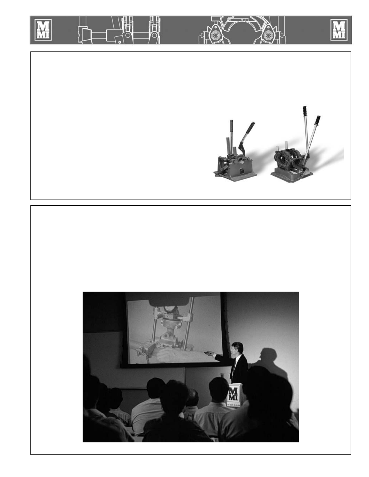
The No.2LC (Locking Cam) and PitBull No.14 model
fusion machines are designed to butt fuse polyethylene
pipe as well as tees, ells and other fittings.
If fusing other thermoplastic pipe materials, refer to the
pipe manufacturer's fusion procedures or appropriate
joining standard.
The No.2LC fuses 1/2‰ CTS to 2‰ IPS (20mm to 60mm).
The PitBull No.14 fuses 1‰ IPS through 4‰ DIPS (32mm
through 122mm) A four-wheel cart is also available.
With reasonable care and maintenance, these machines
will give years of satisfactory service.
TX01083-9-22-09
World Class Training
This manual is intended as a guide only and does not
take the place of proper training by qualified instructors.
The information in this manual is not all inclusive and
can not encompass all possible situations that can be
encountered during various operations.
Before operating this machine, please read this manual
thoroughly, and keep a copy with the machine for future
reference. This manual is to be considered part of your
machine.
PH01848-7-25-00
McElroy Manufacturing, Inc., offers advanced training
classes to enhance efficiency, productivity, safety and
quality. Training is available at our facility or on-site at
your location. Call (918) 836-8611 or visit our website
for online solutions at www.mcelroy.com.
TX01850-7-25-00
PH00917-8-15-97

Warranty
LIMITED WARRANTY
McElroy Manufacturing, Inc. (McElroy) warrants all
products manufactured, sold and repaired by it to be
free from defects in materials and workmanship, its
obligation under this warranty being limited to repairing
or replacing at its factory and new products, within
3 years after shipment, with the exception of purchased
items (such as electronic devices, pumps, switches, etc.),
in which case that manufacturerÊs warranty applies.
Warranty applies when returned freight is prepaid and
which, upon examination, shall disclose to have been
defective. This warranty does not apply to any product
or component which has been repaired or altered by
anyone other than McElroy or has become damaged
due to misuse, negligence or casualty, or has not been
operated or maintained according to McElroyÊs printed
instructions and warnings. This warranty is expressly
in lieu of all other warranties expressed or implied.
The remedies of the Buyer are the exclusive and sole
remedies available and Buyer shall not be entitled to
receive any incidental or consequential damages. Buyer
waives the benefit of any rule that disclaimer of warranty
shall be construed against McElroy and agrees that such
disclaimers herein shall be construed liberally in favor of
McElroy.
RETURN OF GOODS
Buyer agrees not to return goods for any reason except
upon the written consent of McElroy obtained in advance
of such return, which consent, if given, shall specify the
terms and conditions and charges upon which any such
return may be made. Materials returned to McElroy, for
warranty work, repair, etc., must have a Return Material
Authorization (RMA) number, and be so noted on the
package at time of shipment. For assistance, inquiry shall
be directed to:
McElroy Manufacturing, Inc.
P.O. Box 580550
833 North Fulton Street Tulsa, Oklahoma 74158-0550
PHONE: (918) 836ă8611, FAX: (918) 831ă9285.
EMAIL: fusion@McElroy.com
Note: Certain repairs, warranty work, and inquiries may
be directed, at McElroyÊs discretion, to an authorized
service center or distributor.
DISCLAIMER OF LIABILITY
McElroy accepts no responsibility of liability for fusion
joints. Operation and maintenance of the product is the
responsibility of others. We recommend qualified joining
procedures be followed when using McElroy fusion
equipment.
McElroy makes no other warranty of any kind whatever,
express or implied; and all implied warranties of
merchantability and fitness for a particular purpose
which exceed the aforestated obligation are hereby
disclaimed by McElroy.
PRODUCT IMPROVEMENT
McElroy reserves the right to make any changes in or
improvements on its products without incurring any
liability or obligation to update or change previously sold
machines and/or the accessories thereto.
INFORMATION DISCLOSED
No information of knowledge heretofore or hereafter
disclosed to McElroy in the performance of or in
connection with the terms hereof, shall be deemed
to be confidential or proprietary, unless otherwise
expressly agreed to in writing by McElroy and any such
information or knowledge shall be free from restrictions,
other than a claim for patent infringement, is part of the
consideration hereof.
PROPRIETARY RIGHTS
All proprietary rights pertaining to the equipment or
the components of the equipment to be delivered by
McElroy hereunder, and all patent rights therein, arising
prior to, or in the course of, or as a result of the design
or fabrication of the said product, are exclusively the
property of McElroy.
LAW APPLICABLE
All sales shall be governed by the Uniform Commercial
Code of Oklahoma, U.S.A.
Register your product online to activate your
warranty:www.McElroy.com/fusion
(Copy information listed on the machine nameplate here
for your records).
TX02486-04-06-05
Model No.
Serial No.
Date Received
Distributor

Equipment Safety
Safety Alerts . . . . . . . . . . . . . . . . . . . . . . . . . . . . . . . . . . . . . . . . . . 1-1
Read and Understand . . . . . . . . . . . . . . . . . . . . . . . . . . . . . . . . . . . 1-1
General Safety . . . . . . . . . . . . . . . . . . . . . . . . . . . . . . . . . . . . . . . . 1-2
Wear Safety Equipment . . . . . . . . . . . . . . . . . . . . . . . . . . . . . . . . . . 1-2
Heater is Not Explosion Proof . . . . . . . . . . . . . . . . . . . . . . . . . . . . . . 1-2
Electric Motors are Not Explosion Proof . . . . . . . . . . . . . . . . . . . . . . . 1-3
Electrical Safety . . . . . . . . . . . . . . . . . . . . . . . . . . . . . . . . . . . . . . . . 1-3
Facer Blades are Sharp . . . . . . . . . . . . . . . . . . . . . . . . . . . . . . . . . . 1-3
Heater is Hot . . . . . . . . . . . . . . . . . . . . . . . . . . . . . . . . . . . . . . . . . . 1-4
Fusion Procedures . . . . . . . . . . . . . . . . . . . . . . . . . . . . . . . . . . . . . . 1-4
Periodically Check Temperature . . . . . . . . . . . . . . . . . . . . . . . . . . . . . 1-4
Do Not Tow Fusion Machine at Speeds Greater than 5 MPH . . . . . . . . 1-4
Positioning Fusion Machine . . . . . . . . . . . . . . . . . . . . . . . . . . . . . . . 1-5
Transporting 2LC and 2CU Units . . . . . . . . . . . . . . . . . . . . . . . . . . . . 1-5
Overview
Theory of Heat Fusion . . . . . . . . . . . . . . . . . . . . . . . . . . . . . . . . . . . 2-1
PitBull No.14 Cart . . . . . . . . . . . . . . . . . . . . . . . . . . . . . . . . . . . . . . 2-2
Reversible Jaws & Levers . . . . . . . . . . . . . . . . . . . . . . . . . . . . . . . . . 2-3
Outrigger Pipe Supports . . . . . . . . . . . . . . . . . . . . . . . . . . . . . . . . . . 2-3
Electric Facer. . . . . . . . . . . . . . . . . . . . . . . . . . . . . . . . . . . . . . . . . . 2-4
Manual Facer . . . . . . . . . . . . . . . . . . . . . . . . . . . . . . . . . . . . . . . . . 2-4
Cam Lock . . . . . . . . . . . . . . . . . . . . . . . . . . . . . . . . . . . . . . . . . . . . 2-4
Heater . . . . . . . . . . . . . . . . . . . . . . . . . . . . . . . . . . . . . . . . . . . . . . 2-5
Insulated Heater Stand . . . . . . . . . . . . . . . . . . . . . . . . . . . . . . . . . . . 2-5
Table of Contents
Operation
Read Before Operating . . . . . . . . . . . . . . . . . . . . . . . . . . . . . . . . . . 3-1
Prepare Heater . . . . . . . . . . . . . . . . . . . . . . . . . . . . . . . . . . . . . . . . 3-1
Install Clamping Inserts . . . . . . . . . . . . . . . . . . . . . . . . . . . . . . . . . . . 3-2
Loading Pipe into Machine . . . . . . . . . . . . . . . . . . . . . . . . . . . . . . . . 3-2
Inserting Facer . . . . . . . . . . . . . . . . . . . . . . . . . . . . . . . . . . . . . . . . . 3-2
Positioning Pipe in Machine . . . . . . . . . . . . . . . . . . . . . . . . . . . . . . . 3-3
Facing the Pipe Manually . . . . . . . . . . . . . . . . . . . . . . . . . . . . . . . . . 3-3
Electric Facer. . . . . . . . . . . . . . . . . . . . . . . . . . . . . . . . . . . . . . . . . . 3-3
Check Alignment of Pipe . . . . . . . . . . . . . . . . . . . . . . . . . . . . . . . . . 3-4
Check Heater Temperature . . . . . . . . . . . . . . . . . . . . . . . . . . . . . . . . 3-4
Inserting Heater . . . . . . . . . . . . . . . . . . . . . . . . . . . . . . . . . . . . . . . . 3-5
Heating the Pipe . . . . . . . . . . . . . . . . . . . . . . . . . . . . . . . . . . . . . . . 3-5
Fusing the Pipe . . . . . . . . . . . . . . . . . . . . . . . . . . . . . . . . . . . . . . . . 3-5
Optional Use of Torque Wrench . . . . . . . . . . . . . . . . . . . . . . . . . . . . 3-6
Removing Pipe . . . . . . . . . . . . . . . . . . . . . . . . . . . . . . . . . . . . . . . . 3-6
COPYRIGHT © 2009
McELROY MANUFACTURING, INC.
Tulsa, Oklahoma, USA
All rights reserved
All product names or trademarks are property of their respective owners. All information,
illustrations and specifications in this manual are based on the latest information available
at the time of publication. The right is reserved to make changes at any time without notice.

Maintenance
Preventative Maintenance . . . . . . . . . . . . . . . . . . . . . . . . . . . . . . . . . 4-1
Cleaning the Machine . . . . . . . . . . . . . . . . . . . . . . . . . . . . . . . . . . . 4-1
Clean and Lubricate Guide Rods . . . . . . . . . . . . . . . . . . . . . . . . . . . . 4-1
Pivot Pins and Shafts . . . . . . . . . . . . . . . . . . . . . . . . . . . . . . . . . . . . 4-1
Remove Dirt . . . . . . . . . . . . . . . . . . . . . . . . . . . . . . . . . . . . . . . . . . 4-2
Clean and Lubricate Bearings . . . . . . . . . . . . . . . . . . . . . . . . . . . . . . 4-2
Clean Eyebolt Threads . . . . . . . . . . . . . . . . . . . . . . . . . . . . . . . . . . . 4-2
Fasteners Must be Tight . . . . . . . . . . . . . . . . . . . . . . . . . . . . . . . . . . 4-2
Installing Butt Fusion Heater Adapters . . . . . . . . . . . . . . . . . . . . . . . . 4-3
Clean Heater Surfaces . . . . . . . . . . . . . . . . . . . . . . . . . . . . . . . . . . 4-3
Adjusting Heater Temperature . . . . . . . . . . . . . . . . . . . . . . . . . . . . . 4-3
Heater Indicator Light . . . . . . . . . . . . . . . . . . . . . . . . . . . . . . . . . . . . 4-4
Facer and Blades . . . . . . . . . . . . . . . . . . . . . . . . . . . . . . . . . . . . . . . 4-4
Facer Guides . . . . . . . . . . . . . . . . . . . . . . . . . . . . . . . . . . . . . . . . . 4-4
Removable Cam Locks . . . . . . . . . . . . . . . . . . . . . . . . . . . . . . . . . . . 4-5
Maintenance Checklist
Maintenance Checklist . . . . . . . . . . . . . . . . . . . . . . . . . . . . . . . . . . . 5-1
Table of Contents
Determine Fusion Force
Determine Fusion Force . . . . . . . . . . . . . . . . . . . . . . . . . . . . . . . . . . 6-1
Specifications
No.2LC, PitBull No.14 and PitBull No.14 Cart . . . . . . . . . . . . . . . . . . 7-1
TX02481-3-30-05
Fusion Equipment Safety
Safety Alerts
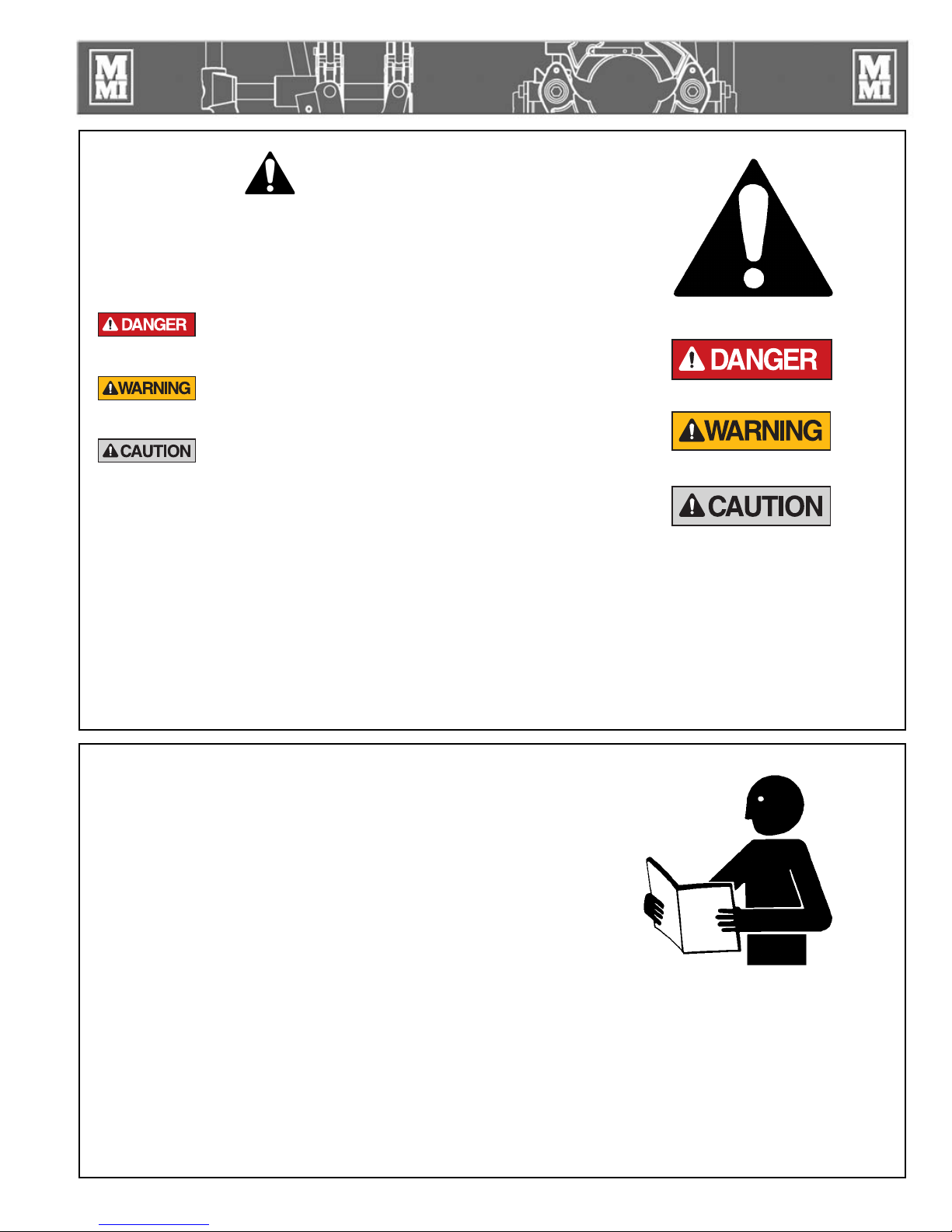
This hazard alert sign appears in this manual.
When you see this sign, carefully read what it says.
YOUR SAFETY IS AT STAKE.
You will see the hazard alert sign with these words:
DANGER, WARNING, and CAUTION.
Indicates an imminently hazardous
situation which, if not avoided, will
result in death or serious injury.
Indicates a potentially hazardous
situation which, if not avoided, could
result in death or serious injury.
Indicates a hazardous situation which,
if not avoided, may result in minor or
moderate injury.
In this manual you should look for two other words:
NOTICE and IMPORTANT.
NOTICE: can keep you from doing something that might
damage the machine or someone's property. It may also
be used to alert against unsafe practices.
IMPORTANT: can help you do a better job or make
your job easier in some way.
WR00051-11-30-92
TX00030-12-1-92
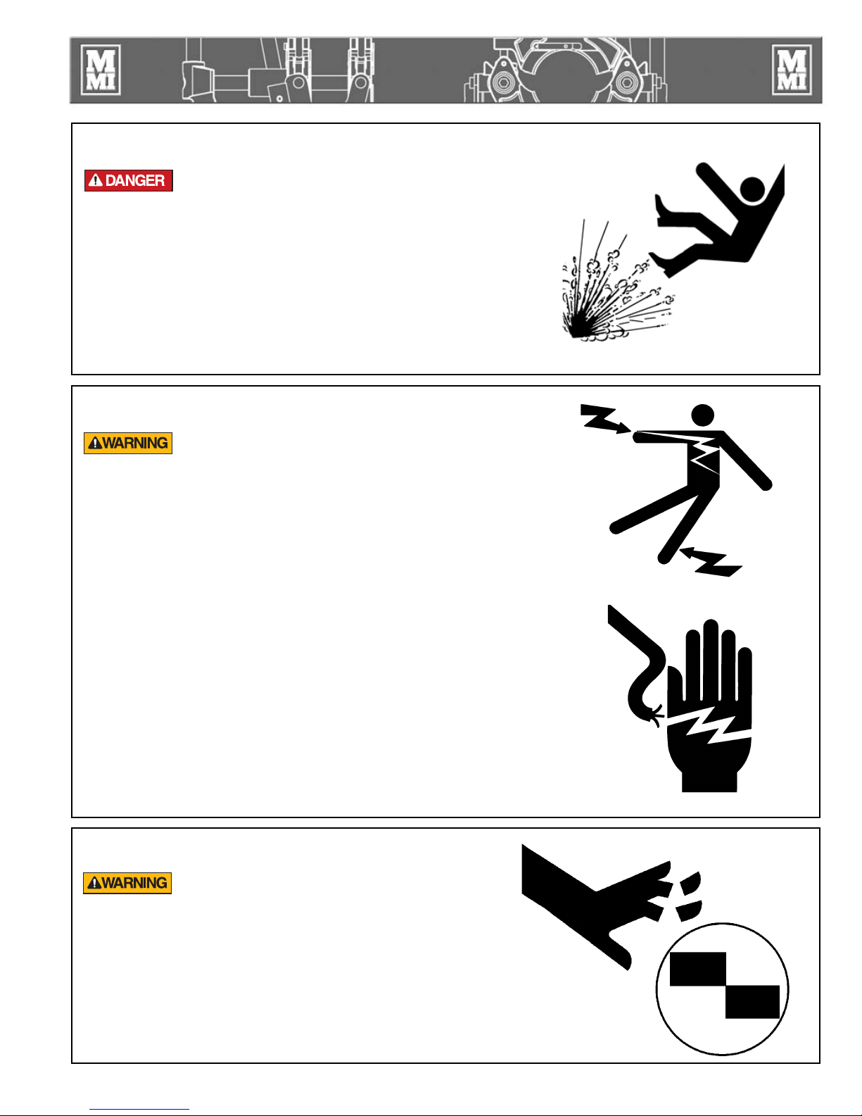
Read and Understand
Do not operate this equipment until you have carefully read, and
understand the "Safety" and "Operation" sections of this manual,
and all other equipment manuals that will be used with it.
Your safety and the safety of others depends upon care and
judgment in the operation of this equipment.
Follow all applicable federal, state, local, and industry specific
regulations.
McElroy Manufacturing, Inc. cannot anticipate every possible
circumstance that might involve a potential hazard. The warnings
in this manual and on the machine are therefore not all inclusive.
You must satisfy yourself that a procedure, tool, work method, or
operating technique is safe for you and others. You should also
ensure that the machine will not be damaged or made unsafe by
the method of operation or maintenance you choose.
TX00031-12-8-92
WR00052-12-1-92
1 - 1

Fusion Equipment Safety
General Safety
Safety is important. Report anything unusual that you notice
during set up or operation.
LISTEN for thumps, bumps, rattles, squeals, air leaks, or unusual
sounds.
SMELL odors like burning insulation, hot metal, burning rubber,
hot oil, or natural gas.
FEEL any changes in the way the equipment operates.
SEE problems with wiring and cables, hydraulic connections, or
other equipment.
REPORT anything you see, feel, smell, or hear that is different from
what you expect, or that you think may be unsafe.
TX00114-4-22-93
SAFE1ST-12-22-92
Wear Safety Equipment
Wear a hard hat, safety shoes, safety glasses, and other
applicable personal protective equipment.
Remove jewelry and rings, and do not wear loose-fitting clothing
or long hair that could catch on controls or moving machinery.
TX00032-4-7-93
Heater Is Not Explosion Proof
This heater is not explosion proof. Operation
of heater in a hazardous environment without
necessary safety precautions will result in
explosion and death.
If operating in a hazardous environment, the heater should be
brought up to temperature in a safe environment, then unplugged
before entering the hazardous atmosphere for fusion.
WR00053-12-2-92
WR00034-11-30-92
TX00100-9-16-94
1 - 2
Fusion Equipment Safety
Electric Motors are Not Explosion Proof
Electric motors are not explosion proof.
Operation of these components in a hazardous
environment without necessary safety precautions
will result in explosion and death.
The armature brushes must be removed from the electric motor
when manually operating in a hazardous condition. Unscrew
the brushes from both sides of the motor. (Both brushes must
be removed). A 7/8" hex shaft allows for manual operation in
hazardous conditions.
TX00873-9-22-09
Electrical Safety
Always ensure power cords are properly
grounded. It is important to remember that you
are working in a wet environment with electrical
devices. Proper ground connections help to
minimize the chances of an electric shock.
Frequently inspect electrical cords and unit for damage. Have
damaged components replaced and service performed by a
qualified electrician.
Do not carry electrical devices by the cord.
NOTICE: Always connect units to the proper power source as
listed on the unit, or in the owner's manual. On units with two
power cords, plug each cord into separate power circuits. Do not
plug into both outlets of one duplex receptacle.
NOTICE: Disconnect the machine from the power source before
attempting any maintenance or adjustment.
WR00080-4-12-93
WR00055-4-7-93
WR00025-11-30-92
TX00105-4-12-93
Facer Blades Are Sharp
Facer blades are sharp and can cut. Never
attempt to remove shavings while the facer is
running, or is in the facing position between the jaws. Use care
when operating the facer, and when handling the unit.
NOTICE: Disconnect power from the facer, and remove the facer
blades before attempting any maintenance or adjustment.
NOTICE: Never extend the blade beyond the inner or outer
circumference of the facer.
TX02378-1-24-05
WR00073-4-6-93
1 - 3
Fusion Equipment Safety
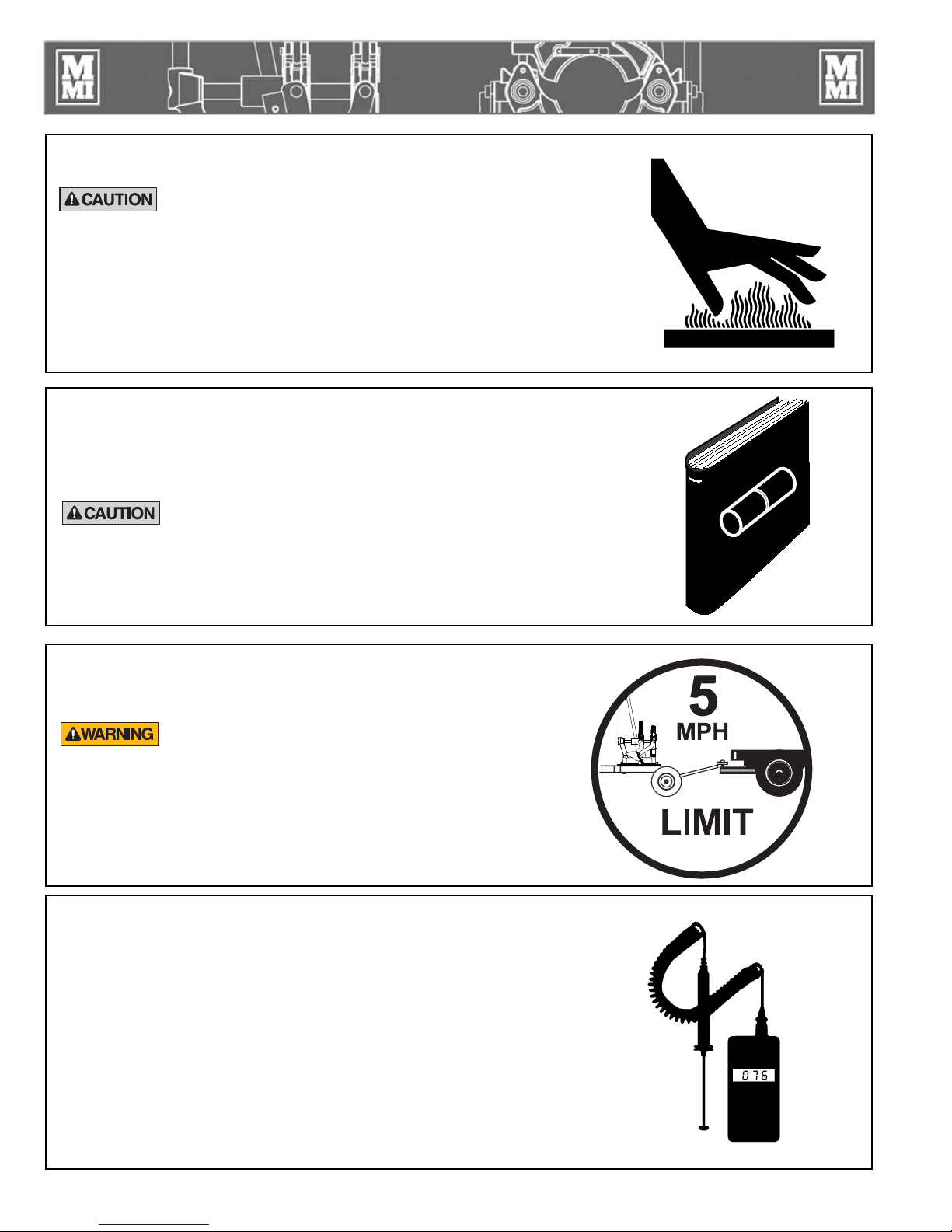
Heater is Hot
The heater is hot and will burn clothing and skin.
Keep the heater in its insulated heater stand or
blanket when not in use, and use care when
heating the pipe.
NOTICE: Use only a clean non-synthetic cloth such as a cotton
cloth to clean the heater plates.
TX00104-8-12-94
Fusion Procedures
Obtain a copy of the pipe manufacturer's procedures or
appropriate joining standard for the pipe being fused. Follow the
procedure carefully, and adhere to all specified parameters.
Failure to follow pipe manufacturer's procedure
could result in a bad joint. Always follow pipe
manufacturer's procedures.
WR00030-2-10-93
WR00079-1-24-96
TX02984-5-4-09
Do Not Tow Fusion Machine at Speeds Greater
than 5 MPH
The chassis is not designed for over-road towing.
Towing at speeds greater than five miles per
hour can result in machine damage as well as
injury. Always transport the machine by flatbed
truck or similar means, and make sure that unit is
properly secured.
TX00101-4-12-93
Periodically Check Temperature
NOTICE: Incorrect heating temperature can result in bad fusion
joints. Check heater plate surface temperature periodically with a
properly calibrated pyrometer, and make necessary adjustments.
The thermometer on heaters indicates internal temperature, and
should be used as a reference only.
CD00632-7-25-00
WR00077-4-16-93
TX00107-11-13-95
1 - 4
Fusion Equipment Safety
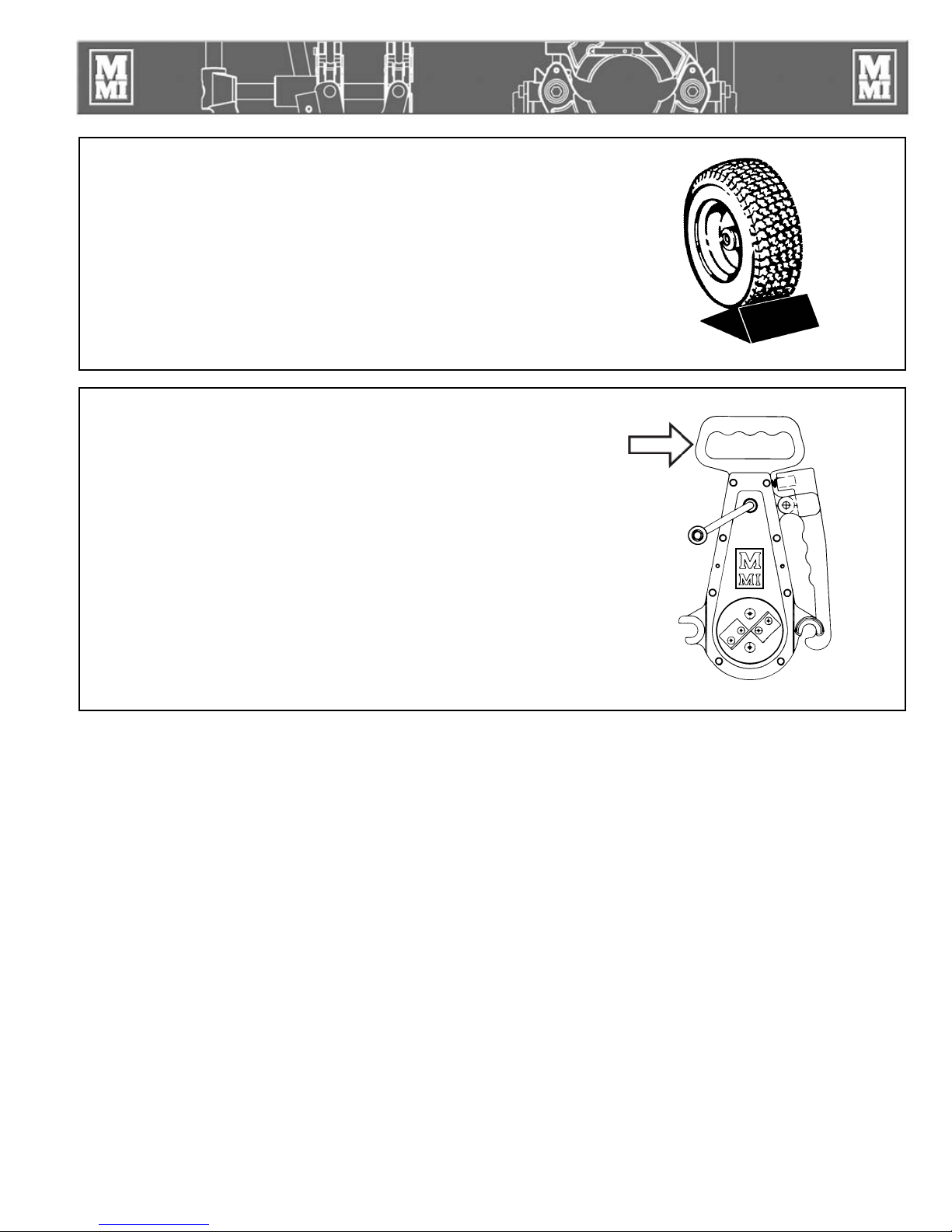
Positioning Fusion Machine
Place fusion machine on as level ground as possible, and set the
brake on the rear wheel. If it is necessary to operate machine on
unlevel grade, chock the wheels and block the unit to make it as
stable as possible.
TX00112-9-15-94
Transporting 2LC and 2CU Units
On smaller machines it is easiest to carry the unit if the facer is
securely installed and locked on the fusion unit. The facer has a
handle that allows the unit to be firmly grasped and carried.
NOTICE: Do not carry unit by the lever handles because they
can release or bend. Care must be used if the unit is grasped
elsewhere because numerous pinch points exist.
WR00076-4-7-93
WR00081-4-22-93
TX00111-4-22-93
1 - 5

Overview
Theory of Heat Fusion
The principle of heat fusion is to heat two surfaces to a
designated temperature, and then fuse them together by
application of force. This pressure causes flow of the melted
materials, which causes mixing and thus fusion. When
the polyethylene pipe is heated, the molecular structure is
transformed from a crystalline state into an amorphous condition.
When fusion pressure is applied, the molecules from each
pipe end mix. As the joint cools, the molecules return to their
crystalline form, the original interfaces are gone, and the two
pipes have become one homogeneous pipe. The joint area
becomes stronger than the pipe itself in both tensile and pressure
conditions.
The principle operations include:
Clamping The pipe pieces held axially to allow all subsequent
operations to take place.
Facing The pipe ends must be faced to establish clean,
parallel mating surfaces perpendicular to the
centerline of the pipes.
Aligning The pipe ends must be aligned with each other to
minimize mismatch or high-low of the pipe walls.
Heating A melt pattern that penetrates into the pipe must be
formed around both pipe ends.
Joining The melt patterns must be joined with a specified
force. The force must be constant around the interface
area.
Holding The molten joint must be held immobile with a
specified force until adequately cooled.
Inspecting Visually examine the entire circumference of the joint
for compliance with standards established by your
company, customer, industry, federal, state, or local
regulations.
PH00363B-1-4-96
Each pipe manufacturer has a slightly different approach for
fulfilling the heating, joining, and holding phases, but the end
result is the same -- a fusion joint that is as strong or stronger than
the pipe itself.
TX02476-3-30-05
2 - 1

Overview
PitBull No.14 Cart
The PitBull No.14 fusion machine can be mounted on a No.14
four wheel cart for mobility and movement along the pipe line.
There is a clamping wheel lock on the left rear wheel to prevent
rolling.
The cart is not designed for over-road towing.
Towing at speeds greater than 5 mph can
result in machine damage as well as injury.
Always transport the machine by flatbed truck
or similar means.
The tongue on the tow bar has a ring to slip over a ball hitch so
the machine can be conveniently maneuvered at the job site.
The cart has outrigger pipe supports that conveniently stow
under the cart when not in use.
The PitBull No.14 Fusion Machine can be mounted on the cart
in any one of three orientations. Older No.14 Fusion Machines
can be mounted in one orientation. The machine is secured
by two mounting posts and a sliding clamp block with an
adjustable clamping lever.
To mount the fusion machine on the cartslide the mounting block
toward the tow bar. Insert one edge of the fusion machine base
under the mounting posts. Slide the clamp block up against the
other edge and secure it with the adjustable clamping lever. To
disengage and swivel the adjustable clamping lever handle pull
up on it by pressing the button with a thumb.
PH01876-7-25-00
PH01891-7-25-00
Please note the mounting position for older style No.14 Fusion
Machine. Use the two inboard mounting posts.
Please note mounting position for newer style PitBull No.14
Fusion Machine. Use the two outboard mounting posts.
TX01843-7-25-00
PH01867-7-25-00
PH01872-7-25-00
2 - 2

Overview
Reversible Jaws & Levers
The No. 14 PitBull upper jaws and control levers are reversible
from one side to the other. This allow the machine to be operated
from either side. The jaws and clamp knobs can be removed by
using a pair of snap ring pliers to release the hinge pins.
The lever handles can be moved from one side to the other by
depressing their spring pins and pulling them out. Put the lever
in the desired socket and make sure its pin engages the hole. The
levers should be on the side opposite the clamp knobs.
Notice: When the top jaws are reversed they should be switched
between lower jaws so that the spring pins are both on the
outboard sides away from the facer blades.
PH01881-7-25-00
PH01880-7-25-00
TX02060-9-20-02
Outrigger Pipe Supports
The PitBull No.14 cart comes equipped with two outrigger
pipe supports that can be used to help line up the pipe in the
machine. When not in use they are fastened with pins under
the cart.
To use the outriggers, simply remove attaching pins, pull
outriggers out and reinstall on the top front and back of the
cart with attaching pins.
The outriggers rest on adjusting screws that can be adjusted
up or down for proper pipe alignment. A wing nut on each
adjusting screw locks the screw setting in place.
TX01844-7-25-00
PH01874-7-25-00
PH01890-7-25-00
PH01873-7-25-00
2 - 3

Overview
Electric Facer
The facer is a McElroy Rotating Planer Block Design. The blade
holders each contain two cutter blades. The block rotates on ball
bearings and is chain driven (enclosed in lubricant) by a heavy
duty electric motor. When operating in a hazardous environment,
operate the facer manually.
Electric motors are not explosion proof.
Operation of these components in a hazardous
environment will result in explosion and death.
The armature brushes must be removed from the electric motor
when manually operating in a hazardous condition. Unscrew
the brushes from both sides of the motor. (Both brushes must
be removed). A 7/8" hex shaft allows for manual operation in
hazardous conditions.
The facer has a handle that latches into place on a guide bar.
The handle must be pulled out to unlatch and remove facer.
The electric facer is symmetrical and can be inserted from either
side.
The facer should be stored in the stand when not in use.
NOTICE: Never extend the blade beyond the inner or outer
circumference of the facer.
PH02330-4-29-02
PH01847-7-25-00
TX02472-03-29-05
Manual Facer
The manually operated facer has a hand powered crank. Turn the
crank counterclockwise for facing.
TX00836-1-5-96
Cam Lock
A semi-automatic cam locking system locks the movable jaw
during the cooling cycle.
PH00657-1-4-96
PH01846-7-25-00
TX00837-1-5-96
2 - 4

Overview
Heater
Heater is not explosion proof. Operation of heater
in a hazardous environment without necessary safety
precautions will result in explosion and death.
If operating in a hazardous environment, heater should be brought up
to temperature in a safe environment, then unplugged before entering
the hazardous atmosphere for fusion.
The heater has a green indicator light which will flash on and off.
This indicates that the controller is operating normally. If the green
indicator is not flashing then the controller may not be operating
properly. If this occurs, disconnect power and have the heater
repaired by a McElroy Authorized Service Center.
The heater temperature is controlled by a microprocessor. It has a red
indicator light on the handle at the bottom of the temperature scale.
When the heater is plugged in and preheating the light glows steadily
until the set temperature is reached. The light then goes off and on
slowly as the heater maintains temperature.
The heater body is not coated. Coated butt fusion heater adapters are
available for all butt fusion applications.
NOTICE: The heater should never be used without butt fusion heater
adapters installed.
To prevent a build-up of plastic pipe residue from accumulating on the
heater plates (loss of surface temperature and pipe sticking may result),
the heater plates should be cleaned with a non-synthetic cloth before
and after every fusion joint.
PH02331-4-29-02
PH02322-4-29-02
TX02216-09-18-03
Insulated Heater Stand
The heater should always be stored in the insulated heater stand
or blanket for protection of the operator and to minimize heat loss
and risk of mechanical damage.
TX00363-9-15-94
PH02330-4-29-02
2 - 5

Operation
Read before Operating
Before operating this machine, please read this manual
thoroughly and keep a copy with the machine for future
reference.
The fusion procedures in this manual are for use with the
polyethylene pipe. If fusing other thermoplastic pipe materials,
refer to the pipe manufacturer's suggested procedures or
appropriate joining standard.
TX00838-9-28-09
Prepare Heater
Heater Is Not Explosion Proof. Operation of
heater in a hazardous environment without
necessary safety precautions will result in
explosion and death.
PH01054-2-20-97
PH02330-4-29-02
If operating in a hazardous environment, heater should be
brought up to temperature in a safe environment, then unplugged
before entering the hazardous atmosphere for fusion.
Install butt fusion heater adapters.
NOTICE: The heater should never be used without butt fusion
heater adapters installed. Refer to the "Maintenance" section of
this manual for installation procedure.
Place heater in insulated heater stand.
Plug heater into a proper power source.
Allow heater to warm-up to operating temperature.
Refer to the "Maintenance" section of this manual for instructions
on how to adjust heater temperature.
TX00366-9-16-94
PH02322-4-29-02
3 - 1

Operation
Install Clamping Inserts
Select and install appropriate clamping inserts for the pipe that is
being fused.
For use with 4" DIPS pipe the 4" IPS masters inserts must be
removed. Pull the spring pins out of their hole and rotate them
outward putting the pin in the jaw pockets. Loosen the insert
attachment screw with the furnished 5/32" hex screwdriver then
rotate the insert in the jaw so the keyhole lines up with the screw
head and pull out the insert.
PH011856-7-25-00
PH01883 -7-25-00
X01846-7-25-00
Loading Pipe Into Machine
Clean the inside and outside of pipe ends that are to be fused.
Open the upper jaws and insert pipe in each pair of jaws with
applicable inserts installed. Let the ends of the pipe protrude
about 1" past the face of the jaws. Close upper jaws but do not
clamp tight.
TX01847-7-25-00
Inserting Facer
Place the end opposite the handle onto the far guide rod, then
lower the facer handle end down onto the near guide rod and
latch.
PH01871-7-25-00
PH01888-7-25-00
TX01851-7-25-00
3 - 2

Operation
Positioning Pipe in Machine
Position the facer on the guide rods and lock into position. Using
lever handle, bring pipe ends together against the facer, watching
the gap between the facer stops and the pipe clamping jaws. Leave
enough gap so that proper face-off will be achieved when the facer
stops are bottomed out against the clamps. Tighten the pipe clamp
knobs by hand until firm resistance is felt. Do not over-tighten.
NOTICE: Thoroughly clean all dirt and debris from pipe ends before
facing.
TX00839-1-5-96
Facing the Pipe Manually
Turn facer handle counterclockwise and apply firm pressure on lever
handle. Continue facing until facer stops have bottomed out against
the clamping jaws. Stop rotation of facer. Move jaws apart.
Unlatch and remove facer. Remove shavings from pipe ends and
machine. Do not touch faced pipe ends.
Inspect both pipe ends for complete face off. If the face off is
incomplete, return to Loading Pipe Into Machine.
PH01870-7-25-00PH001869-7-25-00
TX01848-7-25-00
Electric Facer
The electric facer should be started before the pipe is pushed into
contact with the blades. Continue facing until the facer stops are
against the jaws then turn off the facer while continuing to hold
pressure closed on the lever until the facer stops completely.
Reverse force to the lever handle to move the pipe ends away
from the facer. Unlatch and remove the facer taking care not
to touch the pipe ends. Remove shavings from pipe ends and
machine. Do not touch faced pipe ends as this may contaminate
them.
If after facing any imperfections are visible on the ends of the pipe
move the pipe inward and reface.
Any time clamp knobs are tightened pipe ends should be refaced.
PH01886-7-25-00
TX01851-7-25-00
3 - 3

Operation
Check Alignment of Pipe
Bring the pipe ends together under sufficient force to overcome
any pipe drag or friction in the system. Check for alignment
and proper face off. If high/low (misalignment) exists, adjust by
tightening the clamp on the high side and reface the pipe.
NOTICE: When clamping, do not over-tighten the clamp knobs
because machine damage can result. Check to see if there is
space between the upper and lower jaws. If the two jaws are
touching, do not continue to tighten. Bring the pipe ends together
under fusion pressure plus drag to check for slippage. If slippage
occurs, return to Loading Pipe into Machine.
TX02477-3-30-05
Check Heater Temperature
Incorrect heating temperature can result in
questionable fusion joints. Check heater plates
periodically with a pyrometer and make
necessary adjustments.
Check heater surface temperature.
Refer to the pipe manufacturer's recommendations for proper
heater temperature.
IMPORTANT: The dial thermometer on the heater indicates internal
temperature which varies from the actual surface temperature.
The dial thermometer can be used as reference once the surface
temperature has been verified.
PH01848-7-25-00
WR00077-4-16-93
TX00375-11-1-94
PH02325-4-29-02
3 - 4

Operation
Inserting Heater
Heater Is Not Explosion Proof. This unit is not
explosion proof. Operation of heater in a
hazardous environment without necessary safety
precautions will result in explosion and death.
If operating in a hazardous environment, heater should be brought
up to temperature in a safe environment, then unplugged before
entering the hazardous atmosphere for fusion.
Use a clean non-synthetic cloth to clean the butt fusion heater
adapter surfaces.
Verify heater temperature by noting the reading on the dial
thermometer.
Insert heater between the pipe ends. The stripper bar downward
legs should be outside of the jaws. (not on top)
TX00377-9-15-94
PH02331-4-29-02
Heating the Pipe
With heater in position between the pipe ends, snap pipe ends
sharply against the heater to ensure alignment. Follow the pipe
manufacturer's recommendations for heating time and pressure.
Raise the locking cam into the engaged position while in the
heating cycle.
TX00842-1-8-96
Fusing the Pipe
After the heating cycle is completed, remove the heater and
quickly apply fusion force with the lever handle in accordance
with the pipe manufacturer's recommended fusion procedure or
appropriate joining standard. A torque wrench can be used when
a specified Interfacial Pressure is required. Hold this force for at
least 10 seconds.
After 10 seconds, the locking cams will assist by holding force
during the cooling cycle.
Failure to follow pipe manufacturer's heating
time, pressure and cooling time may result in a
bad joint.
PH01892-7-25-00
PH02327-4-29-02
TX02478-9-22-09
3 - 5

Operation
Optional Use of Torque Wrench
When a specified Interfacial Pressure is required in the fusion
procedure, a torque wrench can be used.
IMPORTANT: Use a torque wrench with the No.14 PitBull place
an adapter in the lever socket (Part # 410802). A 1/2" drive
100 ft-lb 15.0" torque wrench is required when using the torque
wrench adapter. Using a torque wrench of a different length will
result in different forces from the torque reading.
To calculate the proper torque reading see Section "Determine
Fusion Force."
Add the torque required to overcome Drag (the force required to
move the pipe at or near the point of fusion) to the torque reading
to assure the proper joining force. This should be determined
prior to inserting the heater.
Failure to follow pipe manufacturer's heating
time, pressure and cooling time may result in a
bad joint.
PH01885-7-25-00
PH01866-7-25-00
TX02479-9-22-09
Removing Pipe
After pipe has cooled sufficiently, apply closing force on the
lever handle and push the locking cams down into the unlocked
position. Unscrew the clamp knobs enough that they can be
swiveled outward.
TX00844-1-8-96
PH01863-7-25-00
3 - 6

Maintenance
Preventative Maintenance
To insure optimum performance, the machine must be kept clean
and well maintained.
With reasonable care, this machine will give years of service.
Therefore, it is important that a regular schedule of preventive
maintenance be kept.
Store machine inside, out of the weather, whenever possible.
TX00428-8-10-95
Cleaning the Machine
Clean the machine with a soap and water wash as needed.
Remove the heater and facer from the spray area before
cleaning.
CD00142-11-2-94
CD00178-5-3-96
TX00862-1-30-96
Clean and Lubricate Guide Rods
Remove oily dirt buildup from guide rods using WD-40® or
similar solvent and wipe guide rods clean. Do not leave the
cleaning agent on the guide rods.
Remove the 1/16" pipe plugs on each side of the moveable jaw.
Lubricate guide rod bushings with SAE 10W-40 motor oil through
the oil holes on the movable jaw. Replace the pipe plugs.
TX00863-1-30-96
Pivot Pins and Shafts
Occasionally add a drop of oil to pivot pins and shafts.
PH01865-7-25-00
PH01864-7-25-00
TX00864-1-30-96
4 - 1

Maintenance
Remove Dirt
Remove dirt from jaw and insert serrations and clamp knob
eyebolts.
TX00865-1-30-96
Clean and Lubricate Bearings
All clamp knobs are equipped with thrust bearings to reduce
friction and improve efficiency of the clamping screw. Keep
these bearings clean by washing in kerosene or solvent. They
should be lubricated with light machine oil. These bearings must
be replaced if they become inoperative.
PH01858-7-25-00
PH01859-7-25-00PH001859-7-25-00
TX00866-1-30-96
Clean Eyebolt Threads
Keep the clamp knob eyebolt threads brushed clean with a soft
bristle brush. The threads are coated with a black dry lubricant
and do not require oiling.
TX01849-7-25-00
Fasteners Must Be Tight
Check all nuts, bolts, and snap rings to make certain they are
secure and in place.
PH01846-7-25-00
TX00437-9-13-94
4 - 2

Maintenance
Installing Butt Fusion Heater Adapters
The heater body of this assembly is not coated. Coated butt fusion
heater plates are available for all butt fusion applications.
Butt fusion heater adapters are installed with eight Stainless Steel
Cap Screws.
Care should be taken to assure that the butt fusion heater
adapters are seated on the heater body, and that there is no
foreign matter trapped between these surfaces.
IMPORTANT: Do not over tighten the screws.
The surface of the butt fusion heater adapters are coated with an
antistick coating.
TX00443-9-22-94
Clean Heater Surfaces
The heater faces must be kept clean and free of any plastic build
up or contamination.
Before each fusion joint the heater surfaces must be wiped with a
clean, non-synthetic cloth.
NOTICE: Do not use an abrasive pad or steel wool. Use a nonsynthetic cloth that won't damage surfaces.
PH02323-4-29-02
PH02322-4-29-02
TX00440-8-14-08
Adjusting Heater Temperature
Turn knob to desired temperature. Measure the heater surface
temperature with a pyrometer. Any variance must be corrected
to the pyrometer reading.
Loosen setscrew in the knob. Turn knob to point to the same
temperature as the pyrometer. Tighten setscrew in the knob.
Turn knob to desired temperature. Allow heater to stabilize at
the new temperature (5 to 10 minutes) after adjusting.
The thermometer on the heater body indicates internal
temperature and should be used as a reference only.
PH02314-4-29-02
TX02009-3-13-02
4 - 3

Maintenance
Heater Indicator Light
The heater has a green indicator light which will flash on and off.
This indicates that the controller is operating normally. If the green
indicator is not flashing then the controller may not be operating
properly. If this occurs, disconnect power and have the heater
repaired by a McElroy Authorized Service Center.
The heater has a red indicator light on the handle at the bottom
of the temperature scale. When the heater is plugged in and
preheating the light glows steadily until the set temperature is
reached. The light then goes off and on slowly as the heater
maintains temperature.
If the heater is not operating properly, the control will attempt to
turn the heater off and the indicator light will flash rapidly. If this
occurs, disconnect the power and take it to a McElroy Authorized
Service Center for repair.
TX02213-09-16-03
PH02314-4-29-02
PH02571-11-05-03
Facer and Blades
The facers are packed with a high temperature grease at
assembly. The facer does not require repacking of grease.
Inspect the facer blades for damage and sharpness. If dullness or
damage appears on one section of the blade, installing the blade
on the opposite side of the blade holder will normally position a
sharp edge in the facing zone. Chipped or dull blades must be
replaced.
NOTICE: Never extend the blade beyond the inner or outer
circumference of the facer.
TX02473-3-29-05
Facer Guides
To minimize friction on the guide rods, keep the guides clean
using a clean dry cloth to wipe away debris.
PH01860-7-25-00
PH01860-7-25-00
TX02480-3-30-05
4 - 4

Maintenance
Removable Cam Locks
Should the cam locks become worn or damaged they can be
replaced. The cams are attached to the shaft by a keyhole joint
and are held by springs.
TX02728-6-5-07
PH01882-7-25-00
4 - 5

Maintenance Checklist
No.2LC and PitBull No.14 Fusion Machine Checklist
Item to Check Satisfactory Needs Repair Comments
Repair
UNIT
Machine is clean
Clamp knob bearings lubricated and move freely
Movable jaw lubricated and moves freely
Locking cam works properly
Guide rods are not damaged
Clamping jaw and insert grooves are clean
Spring clips work properly
All nuts and bolts are tight
Lever handles are with unit
CHASSIS
Brake and unit lockdown clamps are adjusted
properly
Outrigger adjusting screws work freely
All nuts and bolts are tight
FACER
Check cord, plug and switch
Check for play in blade holder
Facer does not wobble when trapped between jaws
Blades are in good condition
Latch handle locks onto guide rod freely
Facer moves on guide rods without excessive force
Facer is clean and free of grease on blade holder
surface
HEATER
Cord and plug are in good condition
Heater surface is clean and in good condition
Thermometer is in good working order
Surface temperature checked with pyrometer
TX00875-2-9-96
5 - 1

Determining Fusion Force
Variable Definitions
O.D. = Outside Diameter
t = Wall Thickness
∏ = 3.1416
SDR = Standard Dimensional Ratio
IFP = ManufacturerÊs Recommended
Interfacial Pressure
Formulas
O.D.
t = ------------
SDR
AREA = (O.D. - t) x t x ∏
FORCE = AREA x IFP
REQUIRED FORCE = (O.D. - t) ï t ï ∏ ï IFP + DRAG
Example
PH01885-7-25-00
Pipe Size = 4" SDR 11
O.D. of Pipe = 4.5"
SDR of Pipe = 11
Recommended Interfacial Pressure = 75 PSI
Using a Model PitBull No.14 Fusion Unit
O.D. 4.5
t = ------------- = --------------- = 0.409
SDR 11
REQUIRED FORCE = (O.D. - t) ï t ï ∏ ï IFP + DRAG
REQUIRED FORCE = (4.5 - .409) ï .409 ï 3.1416 ï 75 + DRAG = 394 + DRAG
From Table:
30 ft/lbs of Torque = 330 lbs Force
and
40 ft/lbs of Torque = 435 lbs Force
Interpolating between these two values give approximately
36 ft/ lbs Torque.
FUSION FORCE = 36 ft/lbs + Drag (measured in ft/lbs)
TX02482-9-22-09-
This table is only valid when using a torque
wrench and adapter used as shown in the picture above. A 1/2" drive 100 ft-lb 15.0" torque
wrench with the torque wrench adapter. Using a
torque wrench of a different length will result in
different forces from the torque reading.
Torque Wrench No.2LC PitBull No.14
Reading Jaw Axial Force Jaw Axial Force
(Ft Lb) (Lb) (Lb)
10 70 115
20 135 215
30 200 330
40 260 435
50 320 545
60 400 660
70 480 780
80 550 915
90 635 1025
100 690 1140
6 - 1

Specifications
Model No.2LC
Specification:
(20mm to 60mm)
Dimensions:
Width: 14‰ (357mm)
Length: 13‰ (330mm)
Height: 15‰ (381mm)
Weight: 23 lbs. (10.4Kg)
Heater: 800 W, 120 VAC, 60 Hz
(220 V, 50 Hz)
Specifications:
(32mm to 122mm)
Designed for 1/2‰ CTS to 2‰ IPS pipe
Model PitBull No.14
Designed for 1‰ IPS to 4‰ DIPS pipe
Dimensions:
Width: 16.8‰ (425mm)
Length: 15.4‰ (391mm)
Height: 15.5‰ (394mm)
Weight: 37 lbs. (16.8Kg)
Heater: 1200 W, 120 VAC, 60 Hz
(220 V, 50 Hz)
Facer: 7 Amps @ 120 VAC (Running)
22 Amps @ 120 VAC (Stall)
PitBull No.14 Cart
Dimensions
Width: 23‰ (584mm)
Length: 45‰ (1143mm)
Height: 15‰ (381mm)
Weight: 76 lbs. (34.4Kg)
:
TX00975-5-21-99
7 - 1

Optional Accessories
Manual Fusion Machine Stand
The Manual Fusion Machine Stand makes working with the
No.14 and No.2LC much easier. This stand expands to a
comfortable operator level. The height corresponds to the McElroy
pipe stands, PolyPorter™ and PolyHorse™ for easy pipe loading
into the machine. When you are finished, it folds for easy storage
and has wheels for transporting your machine to the next site.
Features:
Ć Designed for use with the No.14 & No.2LC fusion machines
Ć Compatible with McElroy pipe stands, PolyHorse & PolyPorter
Ć Locks in both folded and open positions
Ć More comfortable working height
Ć Wheels for easy transportation
Ć Folds for easy storage
FOLDED
(584mm)
UNFOLDED
11.5”
(292mm)
PH03627-6-8-08
23”
PH03628-6-8-08
22.5” (571mm)
19”
(483mm)
34” (864mm)
23” (584mm)
For more information, contact your distributor or visit www.mcelroy.com.
TX02809-7-8-08
CD00768-7-8-08


About this manual . . .
McElroy Manufacturing continually strives to give customers the best quality products
available. This manual is printed with materials made for durable applications and harsh
environments.
This manual is waterproof, tear resistant, grease resistant, abrasion resistant and the bonding
quality of the printing ensures a readable, durable product.
The material does not contain any cellulose based materials and does not contribute to the
harvesting of our forests, or ozone-depleting constituents. This manual can be safely disposed
of in a landfill and will not leach into ground water.
TX001660-8-19-99

 Loading...