

Operator’s
Manual
6" IPS Pipe Preparation Machine
LineTamer
Manual: LT0104 Revision: J 11/18
Original Language: English
®

Cancer and Reproductive Harm www.P65warnings.ca.gov
This product and other products
could be protected by patents or
have patents pending. All the latest
patent information is available at
patent.mcelroy.com
8163361
Introduction
Thank you for purchasing this McElroy product.
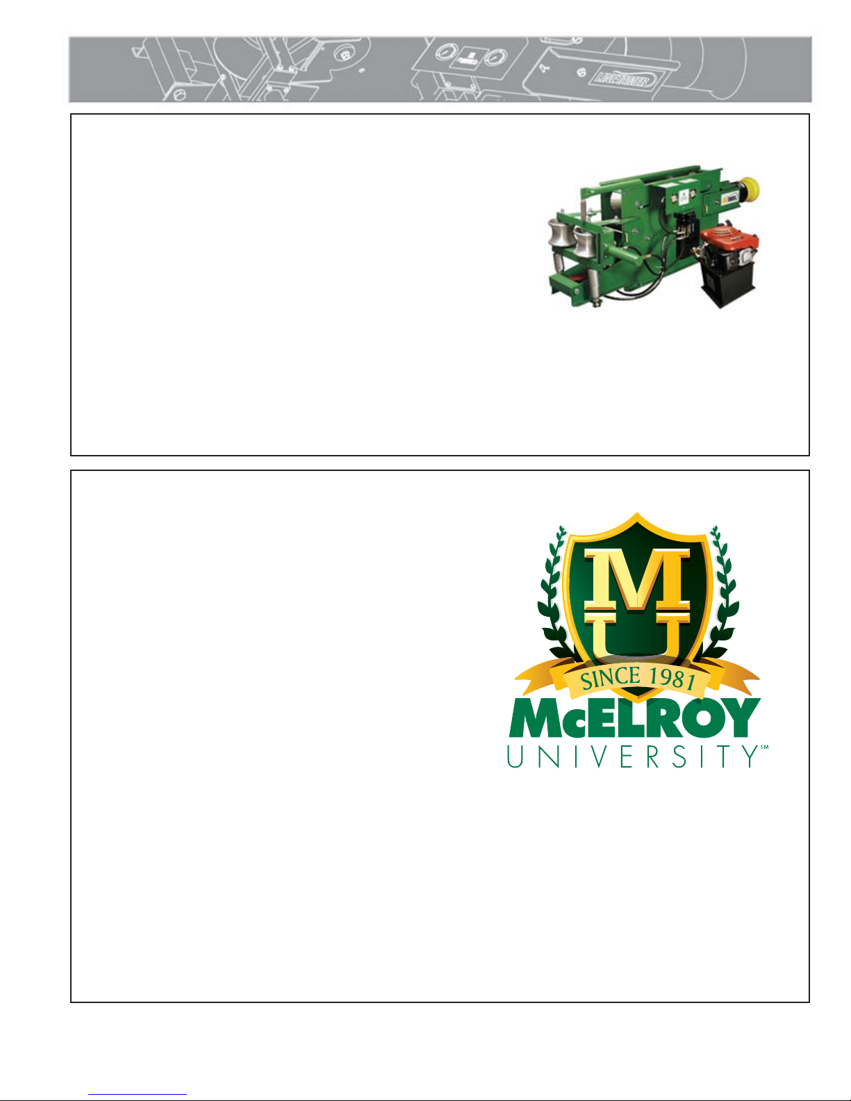
The McElroy LineTamer® is designed to remove coil set and
reround coiled pipe for easier fusion and to minimize the
possibility of dangerous uncontrolled pipe recoil. The LineTamer
consists of a straightening unit and a rerounding unit which
prepares 3" to 6", high and medium density coiled polyethylene
pipe for installation. With reasonable care and maintenance,
this machine will give years of satisfactory service.
Before operating this machine, please read this manual
thoroughly, and keep a copy with the machine for future
reference. This manual is to be considered part of your machine.
TX00569-7-19-95
PH03027-04-26-05
McElroy University
For more than 30 years, McElroy has been the only
pipe fusion machine manufacturer to continuously
offer advanced training. Course offerings are meant to
enhance your efficiency, productivity and safety in the
proper use of McElroy machines. McElroy University
classes are structured so that the skills learned and the
machines used in each class closely match the machines
found on pipelining jobsites. We offer training at
our facility or yours. Our uniquely qualified McElroy
University course instructors offer years of industry
experience.
Tuition for each course includes lunches, course materials
and a certificate of completion. Online registration,
as well as up-to-date course offerings and dates, is
available at www.mcelroy.com/university
This manual is intended as a guide only and does not
take the place of proper training by qualified instructors.
The information in this manual is not all inclusive and
can not encompass all possible situations that can be
encountered during various operations.
MU2-03-13-14
TX04659-03-24-14
Warranty
LIMITED WARRANTY
McElroy Manufacturing, Inc. (McElroy) warrants all
products manufactured, sold and repaired by it to be
free from defects in materials and workmanship, its
obligation under this warranty being limited to repairing
or replacing at its factory and new products, within 5
years after shipment, with the exception of purchased
items (such as electronic devices, pumps, switches, etc.),
in which case that manufacturer’s warranty applies.
Warranty applies when returned freight is prepaid and
which, upon examination, shall disclose to have been
defective. This warranty does not apply to any product
or component which has been repaired or altered by
anyone other than McElroy or has become damaged
due to misuse, negligence or casualty, or has not been
operated or maintained according to McElroy’s printed
instructions and warnings. This warranty is expressly in
lieu of all other warranties expressed or implied. The
remedies of the Buyer are the exclusive and sole remedies
available and Buyer shall not be entitled to receive any
incidental or consequential damages. Buyer waives
the benefit of any rule that disclaimer of warranty shall
be construed against McElroy and agrees that such
disclaimers herein shall be construed liberally in favor of
McElroy.
RETURN OF GOODS
Buyer agrees not to return goods for any reason except
upon the written consent of McElroy obtained in advance
of such return, which consent, if given, shall specify the
terms and conditions and charges upon which any such
return may be made. Materials returned to McElroy, for
warranty work, repair, etc., must have a Return Material
Authorization (RMA) number, and be so noted on the
package at time of shipment. For assistance, inquiry shall
be directed to:
McElroy Manufacturing, Inc.
P.O. Box 580550
833 North Fulton Street Tulsa, Oklahoma 74158-0550
PHONE: (918) 836–8611, FAX: (918) 831–9285.
EMAIL: fusion@McElroy.com
Note: Certain repairs, warranty work, and inquiries may
be directed, at McElroy’s discretion, to an authorized
service center or distributor.
DISCLAIMER OF LIABILITY
McElroy accepts no responsibility of liability for fusion
joints. Operation and maintenance of the product is the
responsibility of others. We recommend qualified joining
procedures be followed when using McElroy fusion
equipment.
McElroy makes no other warranty of any kind whatever,
express or implied; and all implied warranties of
merchantability and fitness for a particular purpose which
exceed the aforestated obligation are hereby disclaimed
by McElroy.
PRODUCT IMPROVEMENT
McElroy reserves the right to make any changes in or
improvements on its products without incurring any
liability or obligation to update or change previously sold
machines and/or the accessories thereto.
INFORMATION DISCLOSED
No information of knowledge heretofore or hereafter
disclosed to McElroy in the performance of or in
connection with the terms hereof, shall be deemed to be
confidential or proprietary, unless otherwise expressly
agreed to in writing by McElroy and any such information
or knowledge shall be free from restrictions, other than a
claim for patent infringement, is part of the consideration
hereof.
PROPRIETARY RIGHTS
All proprietary rights pertaining to the equipment or
the components of the equipment to be delivered by
McElroy hereunder, and all patent rights therein, arising
prior to, or in the course of, or as a result of the design
or fabrication of the said product, are exclusively the
property of McElroy.
LAW APPLICABLE
All sales shall be governed by the Uniform Commercial
Code of Oklahoma, U.S.A.
Register your product online to activate your warranty:
www.McElroy.com/fusion
(Copy information listed on the machine nameplate here
for your records).
TX02486-11-4-13
Model No.
Serial No.
Date Received
Distributor
Table of Contents
Equipment Safety
Safety Alerts . . . . . . . . . . . . . . . . . . . . . . . . . . . . . . . 1-1
Read and Understand . . . . . . . . . . . . . . . . . . . . . . . . 1-1
General Safety . . . . . . . . . . . . . . . . . . . . . . . . . . . . . 1-2
Wear Safety Equipment . . . . . . . . . . . . . . . . . . . . . . . 1-2
Gas Powered Units . . . . . . . . . . . . . . . . . . . . . . . . . . 1-2
Fuel Handling . . . . . . . . . . . . . . . . . . . . . . . . . . . . . . 1-3
Carbon Monoxide. . . . . . . . . . . . . . . . . . . . . . . . . . . 1-3
Keep Personnel Away. . . . . . . . . . . . . . . . . . . . . . . . . 1-3
Cutting Steel Bands . . . . . . . . . . . . . . . . . . . . . . . . . . 1-4
Coiled Pipe Safety. . . . . . . . . . . . . . . . . . . . . . . . . . . 1-4
Pipe Handling Safety . . . . . . . . . . . . . . . . . . . . . . . . . 1-5
Units with Hydraulics . . . . . . . . . . . . . . . . . . . . . . . . . 1-5
Operator’s Seat. . . . . . . . . . . . . . . . . . . . . . . . . . . . . 1-5
Overview
Usage Options . . . . . . . . . . . . . . . . . . . . . . . . . . . . . 2-1
Stringing Pipe . . . . . . . . . . . . . . . . . . . . . . . . . . . . . . 2-1
Stringing and Planting Pipe. . . . . . . . . . . . . . . . . . . . . 2-1
Stringing and Plowing Pipe. . . . . . . . . . . . . . . . . . . . . 2-2
Straightening Pipe for Relining . . . . . . . . . . . . . . . . . . 2-2
Straightening Pipe for Directional Boring . . . . . . . . . . . 2-2
Hydraulic Power Unit . . . . . . . . . . . . . . . . . . . . . . . . . 2-3
Fuel Valve. . . . . . . . . . . . . . . . . . . . . . . . . . . . . . . . . 2-3
Engine Control Lever . . . . . . . . . . . . . . . . . . . . . . . . . 2-3
Hydraulic Fluid . . . . . . . . . . . . . . . . . . . . . . . . . . . . . 2-3
Hydraulic Controls . . . . . . . . . . . . . . . . . . . . . . . . . . . 2-4
Pressure Gauges . . . . . . . . . . . . . . . . . . . . . . . . . . . . 2-4
Rerounding Rollers. . . . . . . . . . . . . . . . . . . . . . . . . . . 2-4
Straightening Rollers . . . . . . . . . . . . . . . . . . . . . . . . . 2-4
Installing LineTamer . . . . . . . . . . . . . . . . . . . . . . . . . . 2-5
Installing Hydraulic Power Unit . . . . . . . . . . . . . . . . . . 2-5
Transporting
Secure Pipe Before Transporting . . . . . . . . . . . . . . . . . 3-1
Lock Machine . . . . . . . . . . . . . . . . . . . . . . . . . . . . . . 3-1
Read Before Towing Trailer . . . . . . . . . . . . . . . . . . . . 3-2
Preparation for Pulling
Connect Trailer . . . . . . . . . . . . . . . . . . . . . . . . . . . . . 4-1
Load Coil . . . . . . . . . . . . . . . . . . . . . . . . . . . . . . . . . 4-1
Securing Pipe when using a Reel. . . . . . . . . . . . . . . . . 4-1
Unlocking Machine . . . . . . . . . . . . . . . . . . . . . . . . . . 4-1
Positioning Pipe Payout. . . . . . . . . . . . . . . . . . . . . . . . 4-2
Rerounder Rollers. . . . . . . . . . . . . . . . . . . . . . . . . . . . 4-2
Straightening Rollers . . . . . . . . . . . . . . . . . . . . . . . . . 4-3
Check Hydraulic Fluid . . . . . . . . . . . . . . . . . . . . . . . . 4-3
All product names or trademarks are property of their respective owners. All information,
illustrations and specifications in this manual are based on the latest information available at the
time of publication. The right is reserved to make changes at any time without notice.
COPYRIGHT © 2018, 2017, 2014, 2008
McELROY MANUFACTURING, INC.
Tulsa, Oklahoma, USA
All rights reserved
Table of Contents
Operation
Read and Understand . . . . . . . . . . . . . . . . . . . . . . . . 5-1
Pulling Force Limitations . . . . . . . . . . . . . . . . . . . . . . . 5-1
Before Starting Operation. . . . . . . . . . . . . . . . . . . . . . 5-2
Start Engine . . . . . . . . . . . . . . . . . . . . . . . . . . . . . . . 5-2
Cutting Steel Bands . . . . . . . . . . . . . . . . . . . . . . . . . . 5-2
Cutting Plastic Bands . . . . . . . . . . . . . . . . . . . . . . . . . 5-2
Pipe Threading Roller Valve . . . . . . . . . . . . . . . . . . . . 5-3
Loading Pipe in LineTamer . . . . . . . . . . . . . . . . . . . . . 5-4
Pressure Settings . . . . . . . . . . . . . . . . . . . . . . . . . . . . 5-6
Rerounder Pressure . . . . . . . . . . . . . . . . . . . . . . . . . . 5-6
Straightener Pressure . . . . . . . . . . . . . . . . . . . . . . . . . 5-6
Monitor Pressure . . . . . . . . . . . . . . . . . . . . . . . . . . . . 5-7
Precautions. . . . . . . . . . . . . . . . . . . . . . . . . . . . . . . . 5-7
End of Coil with Pipe Secured. . . . . . . . . . . . . . . . . . . 5-7
Maintenance
Preventative Maintenance . . . . . . . . . . . . . . . . . . . . . . 6-1
Washing the Machine . . . . . . . . . . . . . . . . . . . . . . . . 6-1
Check Hydraulic Fluid . . . . . . . . . . . . . . . . . . . . . . . . 6-1
Grease Bearing and Sleeves. . . . . . . . . . . . . . . . . . . . 6-1
Grease Moving parts . . . . . . . . . . . . . . . . . . . . . . . . . 6-2
Hydraulic Fluids
Hydraulic Fluids. . . . . . . . . . . . . . . . . . . . . . . . . . . . . 7-1
Specifications
LineTamer . . . . . . . . . . . . . . . . . . . . . . . . . . . . . . . . . 8-1
Hydraulic Power Unit . . . . . . . . . . . . . . . . . . . . . . . . . 8-1
Equipment Safety
Safety Alerts
This hazard alert sign appears in this manual.
When you see this sign, carefully read what it says.
YOUR SAFETY IS AT STAKE.
You will see the hazard alert sign with these words:
DANGER, WARNING, and CAUTION.
Indicates an imminently hazardous
situation which, if not avoided, will
result in death or serious injury.
Indicates a potentially hazardous
situation which, if not avoided, could
result in death or serious injury.
Indicates a hazardous situation which,
if not avoided, may result in minor or
moderate injury.
In this manual you should look for two other words:
NOTICE and IMPORTANT.
NOTICE: can keep you from doing something that might
damage the machine or someone's property. It may also
be used to alert against unsafe practices.
IMPORTANT: can help you do a better job or make
your job easier in some way.
WR00051-11-30-92
TX00030-12-1-92
Read and Understand
Do not operate this equipment until you have carefully read,
and understand all the sections of this manual, and all other
equipment manuals that will be used with it.
Your safety and the safety of others depends upon care and
judgment in the operation of this equipment.
Follow all applicable federal, state, local, and industry specific
regulations.
McElroy Manufacturing, Inc. cannot anticipate every possible
circumstance that might involve a potential hazard. The warnings
in this manual and on the machine are therefore not all inclusive.
You must satisfy yourself that a procedure, tool, work method, or
operating technique is safe for you and others. You should also
ensure that the machine will not be damaged or made unsafe by
the method of operation or maintenance you choose.
WR00052-12-1-92
TX02946-4-15-09
1 - 1
Equipment Safety
General Safety
Safety is important. Report anything unusual that you notice during set
up or operation.
LISTEN for thumps, bumps, rattles, squeals, air leaks, or unusual sounds.
SMELL odors like burning insulation, hot metal, burning rubber, hot oil,
or natural gas.
FEEL any changes in the way the equipment operates.
SEE problems with wiring and cables, hydraulic connections, or other
equipment.
REPORT anything you see, feel, smell, or hear that is different from what
you expect, or that you think may be unsafe.
TX00114-4-22-93
SAFE1ST-12-22-92
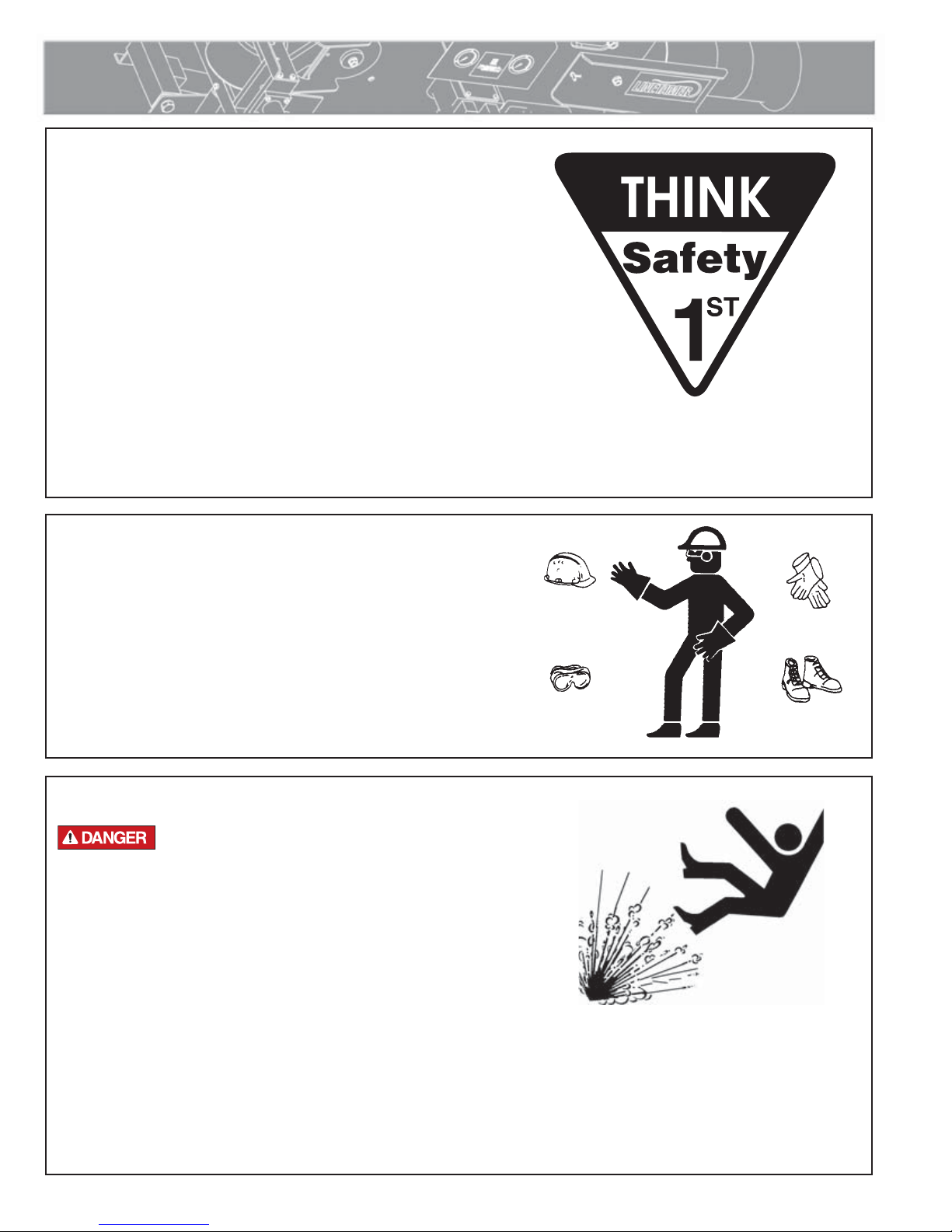
Wear Safety Equipment
Wear a hard hat, safety shoes, safety glasses, and other applicable
personal protective equipment.
Remove jewelry and rings, and do not wear loose fitting clothing or
long hair that could catch on controls or moving machinery.
TX00032 4 7 93
Gas Powered Units
Gasoline engines will cause explosions when
operated in an explosive atmosphere. Do not
operate gas powered machines in an explosive
atmosphere.
Do not place flammable substances near the engine while it is
operating.
A spark arrester is available as an optional part for this engine.
It is illegal in some areas to operate an engine without a spark
arrester. Check local laws and regulations before operating.
WR00053-12-2-92
WR00080-4-12-93
TX00955-06-12-14
1 - 2
Equipment Safety
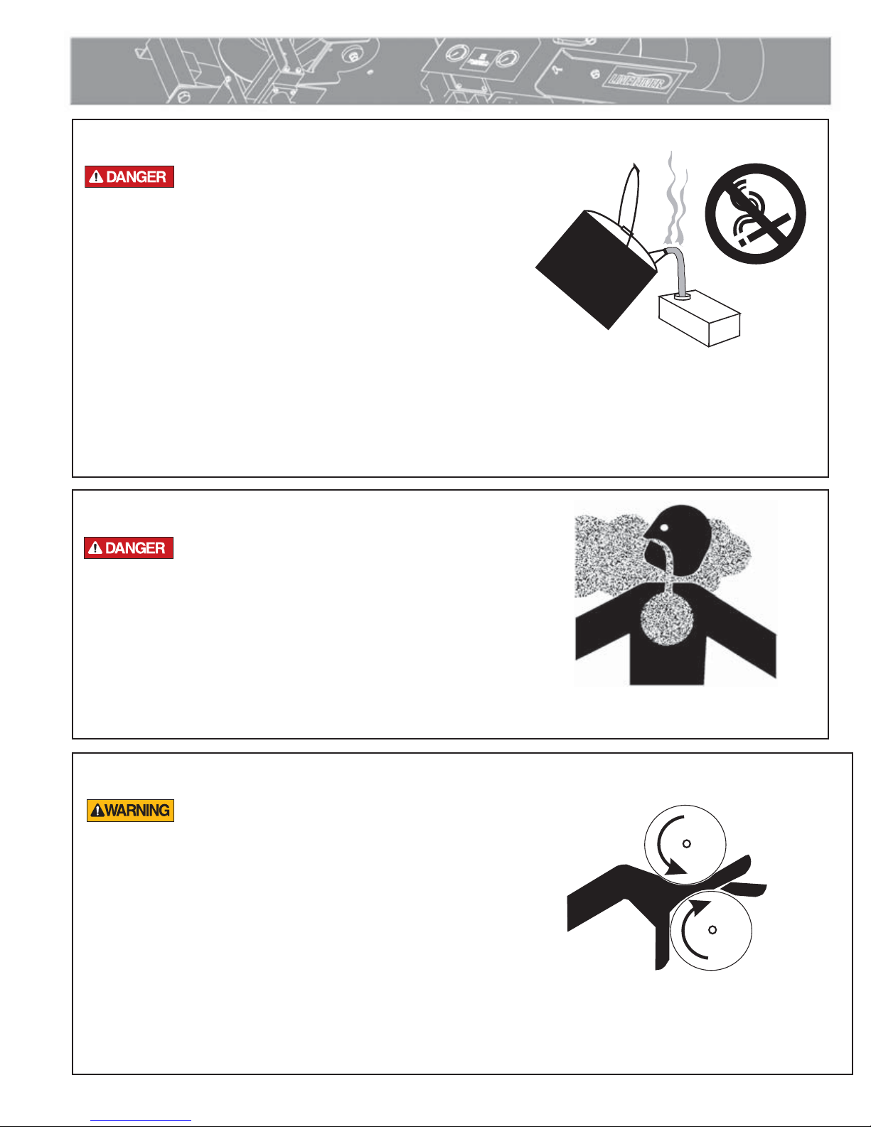
FUEL
Fuel Handling
Gasoline and diesel fuel are extremely flammable and
their vapors will explode if ignited.
Do not fill the fuel tank while the engine is hot or running, as spilled
fuel could ignite.
Refuel in a well ventilated area. Do not smoke or allow flames or
sparks in the area where the engine is refueled, or where gasoline is
stored.
Do not start the engine near spilled fuel. Wipe up spills immediately.
Maker sure the fuel tank cap is closed and properly secured.
NOTICE: Avoid repeated or prolonged contact with skin or breathing of
vapor.
TX00953-3-30-11
CD00365-2-19-97
Carbon Monoxide
Engine exhaust gases contain poisonous carbon
monoxide. Carbon monoxide can cause severe
nausea, fainting and death. Avoid inhaling exhaust
fumes and never run the engine in a closed or
confined area.
TX00954-5-14-96
Keep Personnel Away
The rollers in this machine are under hydraulic
pressure and can cause severe bodily harm. All
personnel must keep hands and body away from
moving parts of machine.
WR00093-5-14-96
CD00155-8-9-95
TX01601-10-12-98
1 - 3
Equipment Safety
Cutting Steel Bands
Coiled pipe can uncoil with considerable force,
causing extreme bodily injury if not properly
contained. Do not cut the straps around the coil
until the coil is contained in a suitable reel trailer
or coil cage.
Leave plastic straps on coil. Do not cut.
TX00618-8-31-95
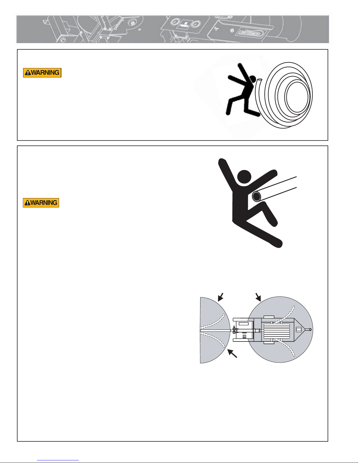
Coiled Pipe Safety
When the tail end of the coil unwinds, or when the
pipe is being cut, the ends can move suddenly in any
direction with great force.
Loose ends of coiled pipe can
move with great force in any direction. Keep
personnel at least 15 feet away.
CD00166-8-31-95
CD00165-8-31-95
When pulling pipe through the LineTamer, personnel
and equipment must stay at least 15 feet away from
machine and pipe ends.
Cold Weather Conditions
The forceful movement of loose ends of pipe become more
pronounced in cold weather and all personnel must be
aware for their own safety.
There are practical limits to pulling pipe in cold weather.
The ability of the pipe to be straightened and rerounded
diminishes.
The LineTamer does not have enough power to properly
straighten and reround pipe at lower temperatures. Operation
below 32° F is not recommended.
PERSONNEL AND EQUIPMENT MUST STAY
AT L EA ST 15 FE ET AWAY FR O M
MACHINE WHEN PULLING PIP
STAND CLEAR OF PIPE
END WHEN CUTTING
E
CD00342-12-17-96
TX01303-3-27-97
1 - 4
Equipment Safety
Pipe Handling Safety
Do not position yourself under supported or
raised pipe. Pipe is heavy and could result in
serious injury or death.
Pipe that is bent can store a great amount of
energy. Do not bend and force the pipe into the
machine. A bent pipe with stored energy could
cause serious injury or death when that energy is
released.
It is recommended that the pipe is always be held securely by
either being clamped securely in the fusion machine jaws or
attached to the lifting device.
Keep persons that are not involved in handling pipe away from handling operations. When the pipe and
handling equipment are in motion, all persons involved in handling pipe should be able to see all other persons
at all times. If any handling person is not in sight, immediately stop moving equipment and pipe and locate that
person. Do not continue until all persons are accounted for and in sight.
NOTICE: Do not leave machine unattended while the Power Pack is running. When not operating the machine,
turn off the Power Pack. This will prevent accidental or unintentional movement of the machine.
Never push, roll, dump or drop pipe lengths, bundles or coils off the truck, off handling equipment or into a
trench. Always use appropriate equipment to lift, move and lower the pipe.
TX04586-4-17-13
WR00097-4-17-13
Units With Hydraulics
Although the hydraulic pressures in this machine are low compared to
some hydraulically operated equipment, it is important to remember
that a sudden hydraulic oil leak can cause serious injury, or even be
fatal if the pressure is high enough.
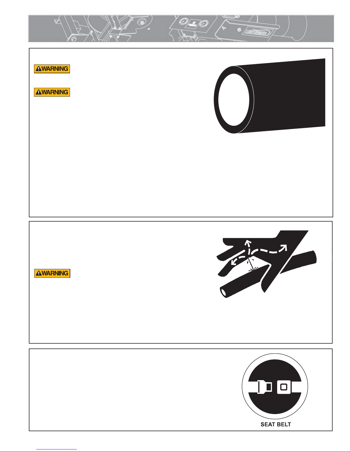
Escaping fluid under pressure can penetrate the
skin causing serious injury. Keep hands and body
away from pinholes which eject fluid under pressure.
Use a piece of cardboard or paper to search for
leaks. If any fluid is injected into the skin, it must be
immediately removed by a doctor familiar with this
type of injury.
NOTICE: Wear safety glasses, and keep face clear of area when
bleeding air from hydraulic system to avoid spraying oil into eyes.
TX00110-8-23-95
Operator's Seat
Always operate the machine from the control side with the operator in the
control seat. Use the seat belt at all times.
Never stand on the LineTamer during operation.
WR00078-4-8-93
CD00167-9-5-95
TX00623-9-5-95
1 - 5

Overview
Usage Options
l: Pulling pipe from LineTamer and stringing the pipe on
the ground for direct burial (in the trench) or relining an
existing pipeline.
ll: Pulling LineTamer behind vehicle with pipe reel or cage
for stringing out straightened pipe along right of way.
lll: Pulling LineTamer behind vehicle with plowing vehicle
pulling pipe directly into the ground.
I: Stringing Pipe
lV: Stationary: LineTamer connected to coil trailer with
plowing vehicle pulling a pipe directly into the ground.
V: Stationary: LineTamer connected to coil trailer with
pipe being pulled through existing pipe for relining.
Vl: Stationary: LineTamer connected to coil trailer with
directional boring unit pulling pipe directly into the
ground.
TX00570-9-19-95
CD00158-8-31-96
II: Stringing Pipe
III: Stringing & Planting Pipe
CD00198-5-1-96
CD00199-5-1-96
2 - 1

III: Stringing & Plowing Pipe
IV: Straightening Pipe for Relining
Overview
CD00161-8-31-95
V: Straightening Pipe for Directional Boring
CD00162-8-31-95
CD00163-8-31-95
2 - 2

Overview
Hydraulic Power Unit
(A) Hydraulic fluid fill.
(B) Gasoline fill.
(C) Starter rope.
(D) Engine oil check and fill.
(E) System pressure gauge
The hydraulics are an open center flow system. The pressure relief valve
is set at 2500 psi.
TX00957-5-14-96
Fuel Valve
The fuel valve should be turned off when transporting the equipment,
or when not being used.
Turn the valve control in to turn off. Turn the control out to turn on.
PH00822B-5-13-96
PH00823-4-26-96
TX00958-5-14-96
Engine Control Lever
All the way back to the left, shuts the engine off. All the way forward
to the right, is the choke position. Between these two positions, the
desired engine speed can be set.
IMPORTANT: Do not use the choke if the engine is warm or the
ambient temperature is high.
TX00959-5-14-96
Hydraulic Fluid
Check fluid level in reservoir. Proper level is indicated on the
sight gauge. If level drops below this point, fill reservoir to the
HIGH level on the sight gauge. Refer to the "Hydraulic Fluids"
section of this manual for hydraulic oil recommendations.
Never allow dirt or other foreign matter to enter the open tank.
PH00823-4-26-96
PH00825-5-2-96
TX00960-5-16-96
2 - 3

Overview
Hydraulic Controls
(A) Rerounder Pressure Control
(B) Straightener Pressure Control
TX01000-6-27-96
Pressure Gauges
The pressure gauge on the left indicates pressure on the
rerounding rollers.
The pressure gauge on the right indicates pressure on the
straightening rollers.
PH00868-6-26-96
PH00855-6-17-96
TX00978-6-17-96
Rerounding Rollers
Pressure to the rerounding rollers is set by a manually operated
control valve.
TX00979-6-17-96
Straightening Rollers
Pressure to the straightening rollers is set by a manually operated
control valve.
PH00854-6-17-96
PH00471-8-9-95
TX00980-6-17-96
2 - 4

Overview
Installing LineTamer
A location should be selected of adequate construction to
support the weight and forces involved with the operation
of the LineTamer. Using the hole pattern dimensions as a
guide, drill four 7/16" holes through the mounting surface.
Use 3/8"-16NC Hex Head Cap Screws of adequate
length. Use 3/8" Type A Wide Flat Washers and 3/8"16NC Finished Hex Nylon Lock Nuts.
CD00374-04-26-05CD00376-04-26-05
TX02487-04-26-05
Installing Hydraulic Power Unit
Drill 7/16" holes at the dimensions shown, or use the four
mounting holes on the HPU as a guide.
Shock mounts are provided to isolate the engine vibration
from the mounting frame.
Install the Shock Mounts in the mounting surface and
secure on the bottom with 3/8" Regular Split Lock
Washers and 3/8"-16NC Finished Hex Nuts.
Position the HPU mounting holes over the shock mounts.
Attach HPU with 3/8" Type A Wide Flat Washers, 3/8"
Regular Split Lock Washers and 3/8"-16NC Finished Hex
Nuts.
CD00375-04-26-05
TX02488-04-26-05
2 - 5

Transporting
Secure Pipe Before Transporting
The coil of pipe should be secured in the trailer before
transporting. Use locking straps or similar means to secure
the coil to itself as well as the trailer frame. This will prevent
damage to the pipe and trailer from shifting loads at trailering
speeds.
If the LineTamer is installed on the same trailer that holds
the pipe coil, pipe from the coil can remain loaded in the
Linetamer.
If the LineTamer is on a different trailer than the coil trailer,
remove the pipe from the LineTamer before transporting.
CD00370-3-31-97
CD00311-3-31-97
TX01304-3-31-97
Lock Machine
Disconnect coil pipe from preparation machine.
Install the yellow-colored transport locking pin to prohibit movement of
pipe guide.
Move seat to position inside trailer and lock into place.
TX00597-8-10-95
PH00486-9-5-95
3 - 1

Transporting
Read Before Towing Trailer
Never tow a trailer before you check to be sure of the following.
Brake fluid is at the proper level.
Coupler and hitch are the right size.
Coupler and safety chains are safely secured to hitch.
Trailer jack is in the raised position.
Check all fasteners for proper tightness.
Wheel lug nuts are properly tightened.
Wheel bearings are properly adjusted and maintained.
Load is within maximum load carrying capacity.
Tires are properly inflated.
All trailer lighting is working properly.
Follow all federal, state local and industry standards when towing a trailer.
PH00808B-6-17-96
TX00918-4-24-96
3 - 2

Preparation for Pulling
Connect Trailer
Connect trailer securely with the hitch and hook up safety chains.
Always use safety chains with proper hookup to
trailer or vehicle.
With trailer secured to vehicle, raise jack up and secure.
TX01305-3-31-97
Load Coil
Load coil on reel, in a cage, on a truck, trailer, or stationary reel
stand. Follow trailer manufacturer's instructions for loading and
unloading coils.
Coiled pipe can uncoil with considerable force,
causing extreme bodily injury if not properly
contained. Do not cut the steel straps around the coil
until the coil is contained in a suitable reel trailer or
coil cage.
TX01910-12-15-00
PH00808B-6-17-96
CD00371-12-15-00
Securing Pipe When Using a Reel
If the pipe coil is mounted on a reel, securing the inside loose end of
the pipe with a rope will prevent the pipe from twisting before it can
enter the pipe preparation machine.
Using a rope with a lower tensile strength than the pipe, secure the
inside loose end of pipe to the reel (this will allow the rope to burst
when the end of the coil is reached).
TX00619-8-31-95
Unlocking Machine
Remove the yellow-colored transport locking pin for free movement of
roller system guide tube and rerounder system.
TX00584-8-10-95
CD00164-8-31-95
PH00486-8-21-95
4 - 1
Preparation for Pulling
Positioning Pipe Payout
Make sure that the pipe payout from the reel or cage is lined up
with the center of the pipe guide. The pipe preparation machine
must be positioned directly in front of the payout from the coil.
IMPORTANT: The pipe may not be straightened or rerounded
properly if the unit is not positioned correctly.
The pipe coil, LineTamer and pulling vehicle must be in alignment
and make a straight pull during operation.
PH00493-8-28-95
CD00179-9-19-95
TX00583-8-10-95
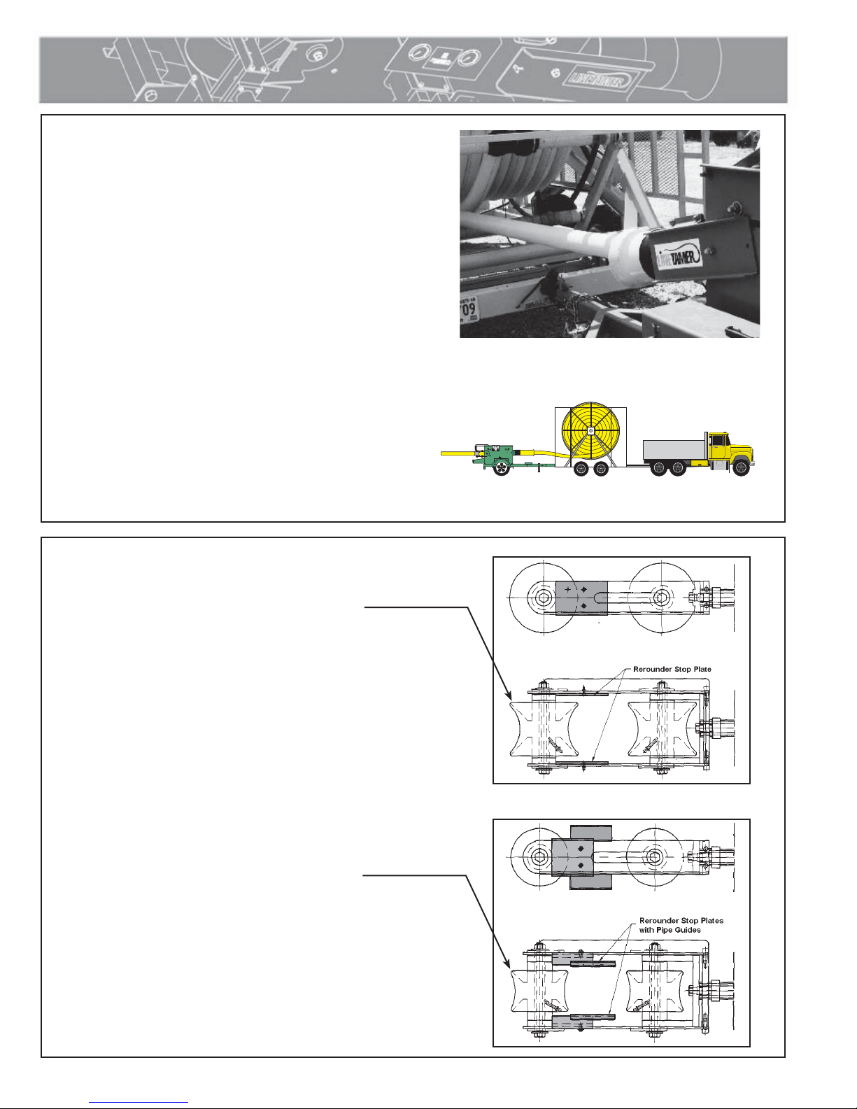
Rerounder Rollers
When changing rerounding rollers, the stop
plates must be installed as shown. Ensure that
the correct rollers and guide blocks are installed
for pipe size being used.
A. 4" to 6" pipe configuration.
B. 4" to 3” configuration.
4" to 6” Roller
CD00174-9-13-95
A
4" to 3” Roller
TX00581-8-10-95
CD00173-9-13-95
B
4 - 2

Straightening Roller
Preparation for Pulling
Confirm that the correct straightening roller position is set for
pipe size to be used.
A. Wide roller setting for 4", 5" and 6" pipe.
B. Narrow roller setting for 3" pipe
TX00580-8-10-95
Check Hydraulic Fluid
Periodically check the hydraulic fluid level in reservoir. All
hydraulic cylinders must be retracted before checking fluid to get
an accurate level. Maintain fluid at HIGH Level.
Never allow dirt or foreign matter to enter the open tank.
Refer to the "Hydraulic Fluids" section of this manual for hydraulic
oil recommendations.
TX00966-5-22-96
A
CD00156-8-21-95
B
PH00825-5-2-96
4 - 3

Operation
Read and Understand
Do not operate this equipment until you have carefully read,
and understand all the sections of this manual, and all other
equipment manuals that will be used with it.
Your safety and the safety of others depends upon care and
judgment in the operation of this equipment.
Follow all applicable federal, state, local, and industry specific
regulations.
McElroy Manufacturing, Inc. cannot anticipate every possible
circumstance that might involve a potential hazard. The warnings
in this manual and on the machine are therefore not all inclusive.
You must satisfy yourself that a procedure, tool, work method, or
operating technique is safe for you and others. You should also
ensure that the machine will not be damaged or made unsafe by
the method of operation or maintenance you choose.
WR00052-12-1-92
TX02946-4-15-09
Pulling Force Limitations
When determining the amount of pulling force required through
the LineTamer, consideration must be given to the amount of drag
on the pipe. The amount of drag can be negligible or more than
the safe pulling strength of the pipe, depending on the terrain
and conditions at the job site.
Nominal pulling force through LineTamer.
3" pipe = 1,250 lbs
4" pipe = 1,800 lbs
5" pipe = 2,000 lbs
6" pipe = 2,400 lbs
Total Force = Nominal + Friction
NOTICE: Total pulling force should never exceed the pipe
manufacturer's safe pulling strength. Exceeding these pulling
forces can damage both pipe and equipment. It may be
necessary to include a force monitoring device or a fusible
link to ensure safe pulling forces are maintained. Slings
and ropes should be of a load rating in excess of the loads
noted above. Do not exceed the rated loads of any pulling
assembly.
PH00494-9-1-95
PH02853-5-15-07
5 - 1

Operation
Before Starting Operation
Always ensure that the pipe and preparation machine are properly
lined up in the pulling direction and that the feed height is equal
to, or higher than the pipe guide.
Always ensure that roller stops are installed before pulling. Check
that roller size is correct for pipe being used.
TX00588-8-10-95
Start Engine
Turn the fuel valve to the ON position. Move the control lever to
the CHOKE position. Pull the starter rope lightly until resistance is
felt, then pull briskly.
NOTICE: Do not allow the starter grip to snap back against the
engine. Return it gently to prevent damage to the starter.
When the engine warms up, move the control lever from the
CHOKE position to the operating position.
STOP-12-22-92
PH00843-5-17-95
TX00963-5-17-96
Cutting Steel Bands
Coiled pipe can uncoil with considerable force,
causing extreme bodily injury if not properly
contained. Do not cut the steel bands around the
coil until the coil is contained in a suitable reel
trailer or coil cage.
Do not cut plastic bands at this time.
TX00590-8-10-95
Cutting Plastic Bands
It may be necessary to cut the plastic bands on the coil during
the pulling operation. These bands can slide together and "bunch
up", posing a possible area for the pipe to kink. Use a long
handled blunt nose cutter to avoid putting arms and hands inside
the coil trailer/cage.
PH00498-9-1-95
PH01129-3-31-97
TX00620-9-1-95
5 - 2

Operation
Pipe Threading Roller Valve
The pipe threading rollers equipped on some trailers can be used
to help guide the starting end of the pipe into the LineTamer.
Use the rollers to pull the pipe down in alignment with the pipe
guide on the LineTamer.
After the pipe is started, move the rollers up to help guide the coil.
PH00844-5-17-96
PH00842-5-17-96
TX00987-6-16-96
5 - 3

Operation
Loading Pipe into LineTamer
Install pulling head in pipe.
Raise threading rollers to highest position and manually roll pipe beneath #1 threading roller.
Attach pulling strap to pulling head.
NOTICE: Use only soft straps or rope to avoid any sharp edges which can damage rollers.
Lower threading roller #1 to align pipe with LineTamer pipe guide.
Second Roller
Rerounding
Rollers
Bottom Roller
First Roller
#1 Threading Roller
CD00706-1-10-06
#2 Threading Roller
Pull pipe just past the first roller and stop.
Raise threading roller #2 to align pipe with second roller.
CD00707-1-10-06
CD00708-1-10-06
TX02580-1-10-06
5 - 4

Operation
Pipe
Rope
Strap
Pipe
Rope
Strap
Loading Pipe into LineTamer (continued)
Pull pipe just past the second roller and stop.
Raise bottom roller in LineTamer to align pipe with the re-rounding rollers and pull pipe through.
CD00709-1-10-06
Rerounding
Rollers
IMPORTANT: The use of a pulling head while loading pipe in
the machine may pose a damage potential to the rollers. Many
pulling heads have strap edges and hard metal surfaces that
could collide with the rollers and cause damage.
An alternative would be to use a strap and rope to pull and align
the pipe in the machine.
To use the strap and rope to load the pipe in the machine, drill
a hole about 2 to 3 inches from the end of the pipe. Thread the
rope through the hole and attach to the strap (as shown). The
strap and rope will pull the pipe downward and forward. This
downward force makes it easier to pass each of the rollers in the
LineTamer.
We recommend a pulling head to payout the coil of pipe as it
provides positive means of attaching to the pipe.
If a pulling head is not available, you can use a similar
arrangement of the strap and rope. Drill two holes inline about 2
to 3 inches from the end of the pipe. Thread the rope through both
holes and attach the strap. Use the strap to pull the pipe to payout
the coil.
TX02579-1-10-06
CD00710-1-10-06
CD00710-1-10-06
CD00710-1-10-06
5 - 5

Operation
Pressure Settings
Charts show pressure settings for various pipe sizes and densities
at different operating temperatures.
Always adjust pressure settings for both rerounder and
straightener systems for changes in temperature. (Higher
temperature = lower setting.)
The LineTamer does not have enough power to properly straighten
and reround pipe at lower temperatures. Operation below 32º F
is not recommended.
IMPORTANT: Charts on machine are range guidelines only for
SDR 11 pipe, at speeds of 50 to 150 ft/min (less than 2 miles
per hour).
Lower speeds will require lower pressure settings.
CD00635-7-16-18
Thinner wall pipe will require lower pressure settings.
Do not exceed 150 ft/min. pulling speed.
TX00592-8-10-95
Rerounder Pressure
Select rerounder pressure control valve and set appropriate
pressure value, based on pipe size and material. Refer to
rerounder pressure chart.
NOTICE: Pressure gauge will indicate a lower pressure than your
initial setting if pull is stopped, but will return to original setting
when the pull begins again. If you adjust the setting while the pull
is stopped, the setting will be higher than necessary when the pull
starts again.
Rerounder pressure setting can be maintained during short stops,
but should be reduced during stops of 10 minutes or more.
TX00988-6-18-96
CD00636-17-16-18
JPH00850B-6-18-96
Straightener Pressure
Select straightener pressure control valve and start pulling pipe slowly
while applying pressure to straightener system. Set appropriate pressure
value, based on pipe size and material. Refer to straightener pressure
chart.
IMPORTANT: Always reduce the pressure on the straightener system
whenever the pipe pull is discontinued. If the pipe pull stops, the
straightener system can kink the pipe when under pressure.
Re-engage when pull is continued, to the initial pressure setting on
straightener gauge.
TX00989-6-18-96
JPH00850B-6-18-96
5 - 6

Operation
Monitor Pressure
Due to variations in temperature and pulling speed, adjustments
may have to be made to pressure settings for the straightener and
rerounder systems to obtain the best results.
IMPORTANT: Final ovality measurements are only reliable after two
hours, due to slow relaxation of pipe.
TX00594-8-10-95
Precautions
Do not operate this equipment until you have carefully read,
and understand all the sections of this manual, and all other
equipment manuals that will be used with it.
Do not stand in front or behind preparation machine during
pulling process.
Always operate machine from control-side of unit.
Operator should always be in radio contact with driver of pulling
vehicle.
Never stand on preparation machine during operation.
Keep hands and legs away from machine during operation.
Do not sit or step on pipe during pull.
All non-participating personnel should be at least 15 feet away
from pipe coil and machine during pull.
PERSONNEL AND EQUIPMENT MUST STAY
AT L EA ST 15 FE ET AWAY FR O M
MACHINE WHEN PULLING PIP
E
PH00855-6-16-96
SAFE1ST-12-22-95
CD00342-12-17-96
TX00586-8-10-95
End of Coil with Pipe Secured
If the pipe coil was mounted on a reel and the inside end tied off,
continue the pull until the pipe has reached the end of the coil.
Do not stop the pull when the rope securing the end of the pipe is
reached. Let the pulling load break the rope. This keeps the pipe
from twisting until the last few feet get to the pipe preparation
machine.
If the pipe twists, it may not be straightened or rerounded properly.
TX00621-9-5-95
5 - 7
STAND CLEAR OF PIPE
END WHEN CUTTING
CD00164-8-31-95

Maintenance
Preventative Maintenance
To insure optimum performance, the machine must be kept clean and
well maintained.
With reasonable care, this machine will give years of service.
Therefore, it is important that a regular schedule of preventive
maintenance be kept.
Store machine inside, out of the weather, whenever possible.
TX00428 -8 -10 -95
Washing the Machine
The machine should be cleaned, as needed with a soap and water
wash.
Do not pressure wash.
CD00142-11-2-94
CD00178-9-15-95
TX00429-04-28-14
Check Hydraulic Fluid
Periodically check the hydraulic fluid level in reservoir. All hydraulic
cylinders must be retracted before checking fluid to get an accurate
level. Maintain fluid at HIGH Level.
Never allow dirt or foreign matter to enter the open tank.
Refer to the "Hydraulic Fluids" section of this manual for hydraulic oil
recommendations.
TX00966-5-22-96
Grease Bearings and Sleeves
Periodically grease all fittings for bearings and sleeves.
PH00825-6-16-96
CD00183-11-6-95
TX00990-6-18-96
6 - 1

Maintenance
Grease Moving Parts
All moving parts should be greased periodically. All pipe rollers
have fittings for lubricating the bearings. Grease the fittings once
a month, or as required.
Grease sliding linkage of rerounder system.
PH00502-9-5-95
PH00503-9-5-95
TX01306-3-31-97
6 - 2

Hydraulic Fluids
Hydraulic Fluids
The use of proper hydraulic fluid is mandatory to achieve maximum performance and machine life. Use a clean, high
quality, anti-wear hydraulic fluid with a viscosity index (VI) of 135 minimum. It should have a maximum viscosity of
500 cSt (2000 SSU) at startup (ambient temperature) and a minimum viscosity of 13 cSt (65 SSU) at the maximum
fluid temperature (generally 80°F above ambient). Using hydraulic fluids that do not meet these criteria may cause
poor operation and/or damage to the hydraulic components.
The following table specifies the fluid temperature at various viscosities. Temperature rise of the hydraulic fluid
can vary from 30° F to about 80° F over the ambient temperature depending on the pressure setting, age of the
pump, wind, etc. Mobil Univis N46 hydraulic fluid is installed at our factory. The advantage of this fluid is a wider
temperature range, however, this fluid should not be used for continuous operation below 24°F.
TX03082-04-18-16
Hydraulic Fluids Characteristics
Manufacturer Fluid Name cSt cSt V.I. -20F -10F 0F 10F 30F 50F 70F 90F 110F 130F 150F Range Range
100F 210F °F °C
Mobil DTE 10 Excel 15 15.8 4.1 168 *********************************************** -16 - 113 -27 - 45
DTE 10 Excel 32 32.7 6.6 164 ********************************************* 12 - 154 -11 - 68
DTE 10 Excel 46 45.6 8.5 164 ********************************************* 23-173 -5 - 78
DTE 10 Excel 68 68.4 11.2 156 ******************************************* 37-196 3 - 91
Univis N-32 34.9 6.9 164 ******************************************** 12-150 -11 - 66
Univis N-46 46 8.5 163 ******************************************** 24-166 -4 - 74
Univis N-68 73.8 12.1 160 ***************************************** 39-193 4 - 89
NOTE: This chart is based on pump manufacturer recommendations of 13 to 500 cSt.
NOTE: Temperatures shown are fluid temperatures. – NOT ambient temperatures.
7 - 1

Specifications
LineTamer
Dimensions: 50'' H x 46” W x 96” L (LineTamer only)
Weight: 730 lbs.
Pipe Capacity: 3", 4", 5" & 6" IPS pipe
4", 5" & 6" Pipe Rollers Standard
(3" & 4" Pipe Rollers Optional)
Hydraulic Power Unit
Fluid: Mobil DTE 15M or equivalent
Reservoir Capacity: 5 gallons
Maximum Pressure: 2500 psi
Flow: 2.0 GPM @ 2000 psi
Engine: Honda 5 HP OHV vertical-shaft engine with electronic ignition
Starting System: Pull Start
Fuel Type: Unleaded
Fuel Tank Capacity: 1.16 QT
CD00302-3-31-97
CD00304-5-20-96
TX00964-5-26-05

About this manual . . .
McElroy Manufacturing continually strives to give customers the best quality products available.
This manual is printed with materials made for durable applications and harsh environments.
This manual is waterproof, tear resistant, grease resistant, abrasion resistant and the bonding
quality of the printing ensures a readable, durable product.
The material does not contain any cellulose based materials and does not contribute to the
harvesting of our forests, or ozone-depleting constituents. This manual can be safely disposed
of in a landfill and will not leach into ground water.
TX001660-8-19-99

 Loading...