


Operator’s
Manual
28, 250, 412 and
28 Sidewall Electric
Pump (EP) Fusion
Machines
Manual: 1272601 Revision: C 10/15
Original Language: English

Introduction
Thank you for purchasing this
McElroy product
The McElroy DynaMc® Electric Pump (EP) fusion
machines are hydraulically operated fusion machines
designed to fuse thermoplastic pipe.
When fusing thermoplastic pipe materials, refer to the
pipe manufacturer's fusion procedures or appropriate
joining standard.
The 28 model fuses 2" IPS (63mm) through 8" DIPS
(225mm) maximum pipe.
The 250 model fuses 63mm (2" IPS) minimum to 250mm
(8" DIPS) maximum pipe.
The 412 model fuses 4” IPS (110mm) minimum to 12"
DIPS (340mm) maximum pipe.
The 28 Sidewall fuses branch saddles up to 8" DIPS
outlet with up to 9 5/8" diameter base on any size
main.
TX04044-04 -08-14
All models utilizes the Electric Pump (EP) Hydraulic Power
Unit (HPU) to provide hydraulic power to the machines.
With reasonable care and maintenance, this machine
will give years of satisfactory service.
Before operating this machine, please read this manual
thoroughly, and keep a copy with the machine for future
reference. This manual is to be considered part of your
machine.
McElroy University
For more than 30 years, McElroy has been the only
pipe fusion machine manufacturer to continuously
offer advanced training. Course offerings are meant to
enhance your efficiency, productivity and safety in the
proper use of McElroy machines. McElroy University
classes are structured so that the skills learned and the
machines used in each class closely match the machines
found on pipelining jobsites. We offer training at
our facility or yours. Our uniquely qualified McElroy
University course instructors offer years of industry
experience.
Tuition for each course includes lunches, course materials
and a certificate of completion. Online registration,
as well as up-to-date course offerings and dates, is
available at www.mcelroy.com/university
This manual is intended as a guide only and does not
take the place of proper training by qualified instructors.
The information in this manual is not all inclusive and
can not encompass all possible situations that can be
encountered during various operations.
MU2-03-13-14
TX04659-03-24-14
Warranty
LIMITED WARRANTY
McElroy Manufacturing, Inc. (McElroy) warrants all
products manufactured, sold and repaired by it to be
free from defects in materials and workmanship, its
obligation under this warranty being limited to repairing
or replacing at its factory and new products, within 5
years after shipment, with the exception of purchased
items (such as electronic devices, pumps, switches, etc.),
in which case that manufacturer’s warranty applies.
Warranty applies when returned freight is prepaid and
which, upon examination, shall disclose to have been
defective. This warranty does not apply to any product
or component which has been repaired or altered by
anyone other than McElroy or has become damaged
due to misuse, negligence or casualty, or has not been
operated or maintained according to McElroy’s printed
instructions and warnings. This warranty is expressly in
lieu of all other warranties expressed or implied. The
remedies of the Buyer are the exclusive and sole remedies
available and Buyer shall not be entitled to receive any
incidental or consequential damages. Buyer waives
the benefit of any rule that disclaimer of warranty shall
be construed against McElroy and agrees that such
disclaimers herein shall be construed liberally in favor of
McElroy.
RETURN OF GOODS
Buyer agrees not to return goods for any reason except
upon the written consent of McElroy obtained in advance
of such return, which consent, if given, shall specify the
terms and conditions and charges upon which any such
return may be made. Materials returned to McElroy, for
warranty work, repair, etc., must have a Return Material
Authorization (RMA) number, and be so noted on the
package at time of shipment. For assistance, inquiry shall
be directed to:
McElroy Manufacturing, Inc.
P.O. Box 580550
833 North Fulton Street Tulsa, Oklahoma 74158-0550
PHONE: (918) 836–8611, FAX: (918) 831–9285.
EMAIL: fusion@McElroy.com
Note: Certain repairs, warranty work, and inquiries may
be directed, at McElroy’s discretion, to an authorized
service center or distributor.
DISCLAIMER OF LIABILITY
McElroy accepts no responsibility of liability for fusion
joints. Operation and maintenance of the product is the
responsibility of others. We recommend qualified joining
procedures be followed when using McElroy fusion
equipment.
McElroy makes no other warranty of any kind whatever,
express or implied; and all implied warranties of
merchantability and fitness for a particular purpose which
exceed the aforestated obligation are hereby disclaimed
by McElroy.
PRODUCT IMPROVEMENT
McElroy reserves the right to make any changes in or
improvements on its products without incurring any
liability or obligation to update or change previously sold
machines and/or the accessories thereto.
INFORMATION DISCLOSED
No information of knowledge heretofore or hereafter
disclosed to McElroy in the performance of or in
connection with the terms hereof, shall be deemed to be
confidential or proprietary, unless otherwise expressly
agreed to in writing by McElroy and any such information
or knowledge shall be free from restrictions, other than a
claim for patent infringement, is part of the consideration
hereof.
PROPRIETARY RIGHTS
All proprietary rights pertaining to the equipment or
the components of the equipment to be delivered by
McElroy hereunder, and all patent rights therein, arising
prior to, or in the course of, or as a result of the design
or fabrication of the said product, are exclusively the
property of McElroy.
LAW APPLICABLE
All sales shall be governed by the Uniform Commercial
Code of Oklahoma, U.S.A.
Register your product online to activate your
warranty:www.McElroy.com/fusion
(Copy information listed on the machine nameplate here
for your records).
TX02486-11-4-13
Model No.
Serial No.
Date Received
Distributor

Equipment Safety
Safety Alerts . . . . . . . . . . . . . . . . . . . . . . . . . . . . . . . . . . . . . . . . . . 1-1
Read and Understand. . . . . . . . . . . . . . . . . . . . . . . . . . . . . . . . . . . . 1-1
General Safety . . . . . . . . . . . . . . . . . . . . . . . . . . . . . . . . . . . . . . . . 1-2
Wear Safety Equipment . . . . . . . . . . . . . . . . . . . . . . . . . . . . . . . . . . 1-2
Heater is Not Explosion Proof . . . . . . . . . . . . . . . . . . . . . . . . . . . . . . 1-2
Electric Motors are Not Explosion Proof . . . . . . . . . . . . . . . . . . . . . . . 1-2
Units with Hydraulics . . . . . . . . . . . . . . . . . . . . . . . . . . . . . . . . . . . . 1-3
Electrical Safety . . . . . . . . . . . . . . . . . . . . . . . . . . . . . . . . . . . . . . . . 1-3
Crush Points . . . . . . . . . . . . . . . . . . . . . . . . . . . . . . . . . . . . . . . . . . 1-4
Facer Blades are Sharp . . . . . . . . . . . . . . . . . . . . . . . . . . . . . . . . . . 1-4
Heater is Hot . . . . . . . . . . . . . . . . . . . . . . . . . . . . . . . . . . . . . . . . . . 1-4
Heavy Lifting . . . . . . . . . . . . . . . . . . . . . . . . . . . . . . . . . . . . . . . . . . 1-4
Fusion Procedures . . . . . . . . . . . . . . . . . . . . . . . . . . . . . . . . . . . . . . 1-5
Overview
Theory of Heat Fusion. . . . . . . . . . . . . . . . . . . . . . . . . . . . . . . . . . . . 2-1
Introduction to the Electric Pump (EP) Fusion Machines . . . . . . . . . . . . . 2-2
Carriage Assembly . . . . . . . . . . . . . . . . . . . . . . . . . . . . . . . . . . . . . . 2-2
DynaMc® EP Hydraulic Power Unit (HPU) . . . . . . . . . . . . . . . . . . . . . . 2-3
Hydraulic Fluid Reservoir . . . . . . . . . . . . . . . . . . . . . . . . . . . . . . . . . . 2-3
Filter . . . . . . . . . . . . . . . . . . . . . . . . . . . . . . . . . . . . . . . . . . . . . . . . 2-4
Hydraulic Manifold Block . . . . . . . . . . . . . . . . . . . . . . . . . . . . . . . . . 2-4
Hydraulic Cylinders . . . . . . . . . . . . . . . . . . . . . . . . . . . . . . . . . . . . . 2-4
Facer . . . . . . . . . . . . . . . . . . . . . . . . . . . . . . . . . . . . . . . . . . . . . . . 2-5
Heater . . . . . . . . . . . . . . . . . . . . . . . . . . . . . . . . . . . . . . . . . . . . . . 2-6
Insulated Heater Stand . . . . . . . . . . . . . . . . . . . . . . . . . . . . . . . . . . . 2-6
Stripper Bar. . . . . . . . . . . . . . . . . . . . . . . . . . . . . . . . . . . . . . . . . . . 2-7
Carriage Shut-off Valve . . . . . . . . . . . . . . . . . . . . . . . . . . . . . . . . . . . 2-7
Clamp Knobs . . . . . . . . . . . . . . . . . . . . . . . . . . . . . . . . . . . . . . . . . 2-7
Table of Contents
All product names or trademarks are property of their respective owners. All information,
illustrations and specifications in this manual are based on the latest information available
at the time of publication. The right is reserved to make changes at any time without notice.
COPYRIGHT © 2015, 2014, 2010
McELROY MANUFACTURING, INC.
Tulsa, Oklahoma, USA
All rights reserved

Butt Fusion Procedure
Read Before Operating . . . . . . . . . . . . . . . . . . . . . . . . . . . . . . . . . . . 3-1
Check Fluid Level . . . . . . . . . . . . . . . . . . . . . . . . . . . . . . . . . . . . . . . 3-1
Connecting to Power . . . . . . . . . . . . . . . . . . . . . . . . . . . . . . . . . . . . 3-1
Prepare Heater . . . . . . . . . . . . . . . . . . . . . . . . . . . . . . . . . . . . . . . . 3-2
Pipe Supports . . . . . . . . . . . . . . . . . . . . . . . . . . . . . . . . . . . . . . . . . 3-2
Install Clamping Inserts . . . . . . . . . . . . . . . . . . . . . . . . . . . . . . . . . . . 3-2
Hydraulic Power Unit (HPU) . . . . . . . . . . . . . . . . . . . . . . . . . . . . . . . . 3-3
Facer . . . . . . . . . . . . . . . . . . . . . . . . . . . . . . . . . . . . . . . . . . . . . . . 3-4
Hydraulic Pressure . . . . . . . . . . . . . . . . . . . . . . . . . . . . . . . . . . . . . . 3-5
Jaw Configuration . . . . . . . . . . . . . . . . . . . . . . . . . . . . . . . . . . . . . . 3-6
Loading Pipe Into Machine . . . . . . . . . . . . . . . . . . . . . . . . . . . . . . . . 3-6
Clamp the Pipe . . . . . . . . . . . . . . . . . . . . . . . . . . . . . . . . . . . . . . . . 3-7
Begin Facing . . . . . . . . . . . . . . . . . . . . . . . . . . . . . . . . . . . . . . . . . . 3-7
After Facing . . . . . . . . . . . . . . . . . . . . . . . . . . . . . . . . . . . . . . . . . . 3-8
Determine Drag Pressure . . . . . . . . . . . . . . . . . . . . . . . . . . . . . . . . . . 3-9
Calculate Fusion Pressure . . . . . . . . . . . . . . . . . . . . . . . . . . . . . . . . . 3-9
Check for Slippage . . . . . . . . . . . . . . . . . . . . . . . . . . . . . . . . . . . . . 3-9
Check Alignment . . . . . . . . . . . . . . . . . . . . . . . . . . . . . . . . . . . . . . . 3-10
Position Carriage for Heater Insertion . . . . . . . . . . . . . . . . . . . . . . . . . 3-10
Check Heater Temperature . . . . . . . . . . . . . . . . . . . . . . . . . . . . . . . . 3-11
Select the Fusion Position. . . . . . . . . . . . . . . . . . . . . . . . . . . . . . . . . . 3-11
Inserting Heater . . . . . . . . . . . . . . . . . . . . . . . . . . . . . . . . . . . . . . . . 3-12
Heating the Pipe . . . . . . . . . . . . . . . . . . . . . . . . . . . . . . . . . . . . . . . 3-12
Fusing the Pipe . . . . . . . . . . . . . . . . . . . . . . . . . . . . . . . . . . . . . . . . 3-13
Opening Jaws . . . . . . . . . . . . . . . . . . . . . . . . . . . . . . . . . . . . . . . . . 3-13
Position Pipe for Next Joint . . . . . . . . . . . . . . . . . . . . . . . . . . . . . . . . 3-14
Install Next Piece of Pipe. . . . . . . . . . . . . . . . . . . . . . . . . . . . . . . . . . 3-14
Table of Contents
Special Operations - In Ditch
Remove Carriage from Skid . . . . . . . . . . . . . . . . . . . . . . . . . . . . . . . . 4-1
Lower the Carriage into Ditch . . . . . . . . . . . . . . . . . . . . . . . . . . . . . . 4-2
Removing Top Jaws . . . . . . . . . . . . . . . . . . . . . . . . . . . . . . . . . . . . . 4-3
Clamp Carriage Assembly to Pipe . . . . . . . . . . . . . . . . . . . . . . . . . . . 4-3
Make Fusion Joint . . . . . . . . . . . . . . . . . . . . . . . . . . . . . . . . . . . . . . 4-4
Remove Carriage Assembly from Ditch . . . . . . . . . . . . . . . . . . . . . . . . 4-4
Attach Carriage to Skid . . . . . . . . . . . . . . . . . . . . . . . . . . . . . . . . . . 4-4
Special Operations - Saddle Fusion Procedures
Saddle Fusion Procedure . . . . . . . . . . . . . . . . . . . . . . . . . . . . . . . . . . 5-1
Install Heater Adapters . . . . . . . . . . . . . . . . . . . . . . . . . . . . . . . . . . . 5-1
Assure Saddle Will Fit . . . . . . . . . . . . . . . . . . . . . . . . . . . . . . . . . . . 5-1
Install Clamping Inserts . . . . . . . . . . . . . . . . . . . . . . . . . . . . . . . . . . . 5-2
Attach Carriage Assembly to Main . . . . . . . . . . . . . . . . . . . . . . . . . . 5-2
Hydraulic Manifold Block . . . . . . . . . . . . . . . . . . . . . . . . . . . . . . . . . 5-2
Set Hydraulic Pressure . . . . . . . . . . . . . . . . . . . . . . . . . . . . . . . . . . . 5-2
Clean Surfaces . . . . . . . . . . . . . . . . . . . . . . . . . . . . . . . . . . . . . . . . 5-2
Clamp Fitting . . . . . . . . . . . . . . . . . . . . . . . . . . . . . . . . . . . . . . . . . . 5-3
Test for Slippage . . . . . . . . . . . . . . . . . . . . . . . . . . . . . . . . . . . . . . . 5-3
Prepare Heater . . . . . . . . . . . . . . . . . . . . . . . . . . . . . . . . . . . . . . . . 5-3

Table of Contents
Special Operations - Saddle Fusion Procedures (Continued)
Inserting Heater . . . . . . . . . . . . . . . . . . . . . . . . . . . . . . . . . . . . . . . . 5-4
Heat Pipe and Fitting . . . . . . . . . . . . . . . . . . . . . . . . . . . . . . . . . . . . 5-5
Remove Heater . . . . . . . . . . . . . . . . . . . . . . . . . . . . . . . . . . . . . . . . 5-5
Fuse Fitting to Pipe . . . . . . . . . . . . . . . . . . . . . . . . . . . . . . . . . . . . . . 5-5
Allow Joint to Cool . . . . . . . . . . . . . . . . . . . . . . . . . . . . . . . . . . . . . . 5-6
Special Operations - Lifting Fusion Machine
Lifting Safety . . . . . . . . . . . . . . . . . . . . . . . . . . . . . . . . . . . . . . . . . . 6-1
Manual Lifting . . . . . . . . . . . . . . . . . . . . . . . . . . . . . . . . . . . . . . . . . 6-1
Powered Lifting . . . . . . . . . . . . . . . . . . . . . . . . . . . . . . . . . . . . . . . . 6-2
Maintenance
Preventative Maintenance . . . . . . . . . . . . . . . . . . . . . . . . . . . . . . . . . 7-1
Washing the Machine . . . . . . . . . . . . . . . . . . . . . . . . . . . . . . . . . . . 7-1
Check Hydraulic Fluid . . . . . . . . . . . . . . . . . . . . . . . . . . . . . . . . . . . . 7-1
Change Hydraulic Fluid and Filter . . . . . . . . . . . . . . . . . . . . . . . . . . . 7-1
Accumulator Charge . . . . . . . . . . . . . . . . . . . . . . . . . . . . . . . . . . . . 7-2
Check Pressure Gauges . . . . . . . . . . . . . . . . . . . . . . . . . . . . . . . . . . 7-2
Clean Jaws and Inserts . . . . . . . . . . . . . . . . . . . . . . . . . . . . . . . . . . . 7-2
Clean Thrust Bearings . . . . . . . . . . . . . . . . . . . . . . . . . . . . . . . . . . . . 7-2
Clean Eyebolt Threads . . . . . . . . . . . . . . . . . . . . . . . . . . . . . . . . . . . 7-3
Clean the Clamping Chains . . . . . . . . . . . . . . . . . . . . . . . . . . . . . . . 7-3
Fasteners Must Be Tight. . . . . . . . . . . . . . . . . . . . . . . . . . . . . . . . . . . 7-3
Facer Blades . . . . . . . . . . . . . . . . . . . . . . . . . . . . . . . . . . . . . . . . . . 7-3
Clean Heater Surfaces . . . . . . . . . . . . . . . . . . . . . . . . . . . . . . . . . . . 7-4
Bleeding Air From Hydraulic System . . . . . . . . . . . . . . . . . . . . . . . . . . 7-4
Installing Butt Fusion Heater Plates . . . . . . . . . . . . . . . . . . . . . . . . . . . 7-5
Adjusting Heater Temperature . . . . . . . . . . . . . . . . . . . . . . . . . . . . . . 7-5
Heater Indicator Light . . . . . . . . . . . . . . . . . . . . . . . . . . . . . . . . . . . . 7-5
Machine Maintenance Checklist
Fusion Machine Checklist . . . . . . . . . . . . . . . . . . . . . . . . . . . . . . . . . 8-1
Determining Fusion Pressure
Determining Fusion Pressure . . . . . . . . . . . . . . . . . . . . . . . . . . . . . . . 9-1
Determining Fusion Pressure - Sidewall . . . . . . . . . . . . . . . . . . . . . . . . 9-2
Hydraulic Fluid
Hydraulic Fluid Characteristics . . . . . . . . . . . . . . . . . . . . . . . . . . . . . . 10-1
Specifications
Fusion Machine Specifications . . . . . . . . . . . . . . . . . . . . . . . . . . . . . . 11-1
Generator Sizing Form . . . . . . . . . . . . . . . . . . . . . . . . . . . . . . . . . . . 11-3
TX04046-04-15-15
Fusion Equipment Safety
Safety Alerts
This hazard alert sign appears in this manual.
When you see this sign, carefully read what it says.
YOUR SAFETY IS AT STAKE.
You will see the hazard alert sign with these words:
DANGER, WARNING, and CAUTION.
Indicates an imminently hazardous
situation which, if not avoided, will
result in death or serious injury.
Indicates a potentially hazardous
situation which, if not avoided, could
result in death or serious injury.
Indicates a hazardous situation which,
if not avoided, may result in minor or
moderate injury.
In this manual you should look for two other words:
NOTICE and IMPORTANT.
NOTICE: can keep you from doing something that might
damage the machine or someone's property. It may also
be used to alert against unsafe practices.
IMPORTANT: can help you do a better job or make
your job easier in some way.
WR00051-11-30-92
TX00030-12-1-92
Read and Understand
Do not operate this equipment until you have carefully read, and
understand all the sections of this manual, and all other equipment
manuals that will be used with it.
Your safety and the safety of others depends upon care and
judgment in the operation of this equipment.
Follow all applicable federal, state, local, and industry specific
regulations.
McElroy Manufacturing, Inc. cannot anticipate every possible
circumstance that might involve a potential hazard. The warnings
in this manual and on the machine are therefore not all inclusive.
You must satisfy yourself that a procedure, tool, work method, or
operating technique is safe for you and others. You should also
ensure that the machine will not be damaged or made unsafe by
the method of operation or maintenance you choose.
WR00052-12-1-92
TX02946-4-15-09
1 - 1
Fusion Equipment Safety
General Safety
Safety is important. Report anything unusual that you notice during
set up or operation.
LISTEN for thumps, bumps, rattles, squeals, air leaks, or unusual
sounds.
SMELL odors like burning insulation, hot metal, burning rubber, hot
oil, or natural gas.
FEEL any changes in the way the equipment operates.
SEE problems with wiring and cables, hydraulic connections, or other
equipment.
REPORT anything you see, feel, smell, or hear that is different from
what you expect, or that you think may be unsafe.
TX00114-4-22-93
Wear Safety Equipment
Wear a hard hat, safety shoes, safety glasses, and other
applicable personal protective equipment.
Remove jewelry and rings, and do not wear loose-fitting clothing
or long hair that could catch on controls or moving machinery.
SAFE1ST-12-22-92
WR00053-12-2-92
TX00032-4-7-93
Heater Is Not Explosion Proof
This heater is not explosion proof. Operation of heater
in an explosive atmosphere without necessary safety
precautions will result in serious injury or death.
When operating in an explosive atmosphere, the heater should be brought
up to temperature in a safe environment, then unplugged before entering
the explosive atmosphere for fusion.
TX04467-03-24-14
Electric Motors are Not Explosion Proof
Electric motors are not explosion proof. Operation of
these components in an explosive atmosphere without
necessary safety precautions will result in serious injury
or death.
See Section "Facer" in the Overview section for instructions on
removing brushes from the facer motor.
WR00034-11-30-92
WR00080-4-12-93
TX02979-04-02-14
1 - 2
Fusion Equipment Safety
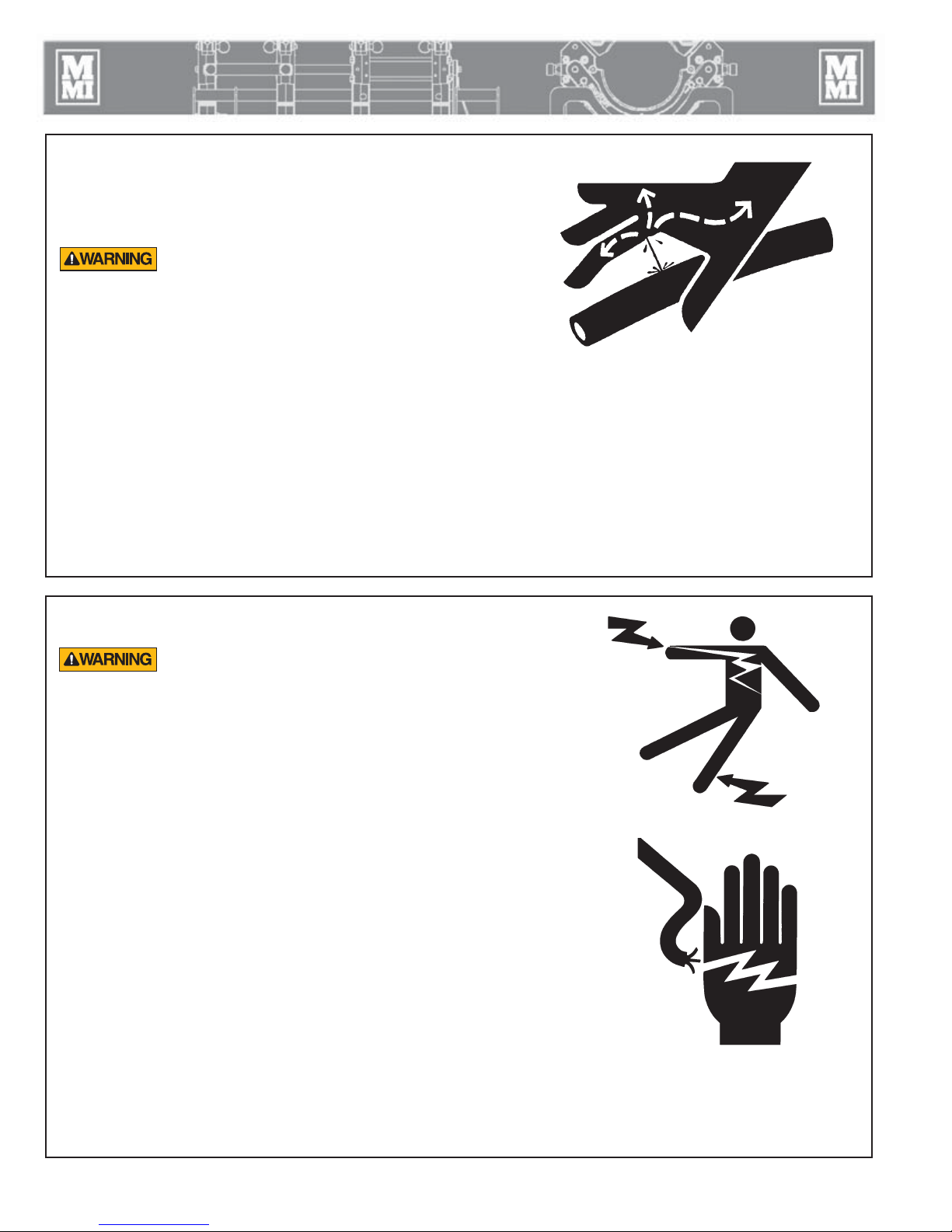
Units With Hydraulics
For hydraulically operated equipment, it is important to remember
that a sudden hydraulic oil leak can cause serious injury, or even
be fatal if the pressure is high enough.
Escaping fluid under pressure can penetrate the
skin causing serious injury. Keep hands and
body away from pinholes which eject fluid under
pressure. Use a piece of cardboard or paper to
search for leaks. If any fluid is injected into the
skin, it must be immediately removed by a doctor
familiar with this type of injury.
NOTICE: Wear safety glasses, and keep face clear of area when
bleeding air from hydraulic system to avoid spraying oil into eyes.
WR00078-4-8-93
TX03077-2-16-10
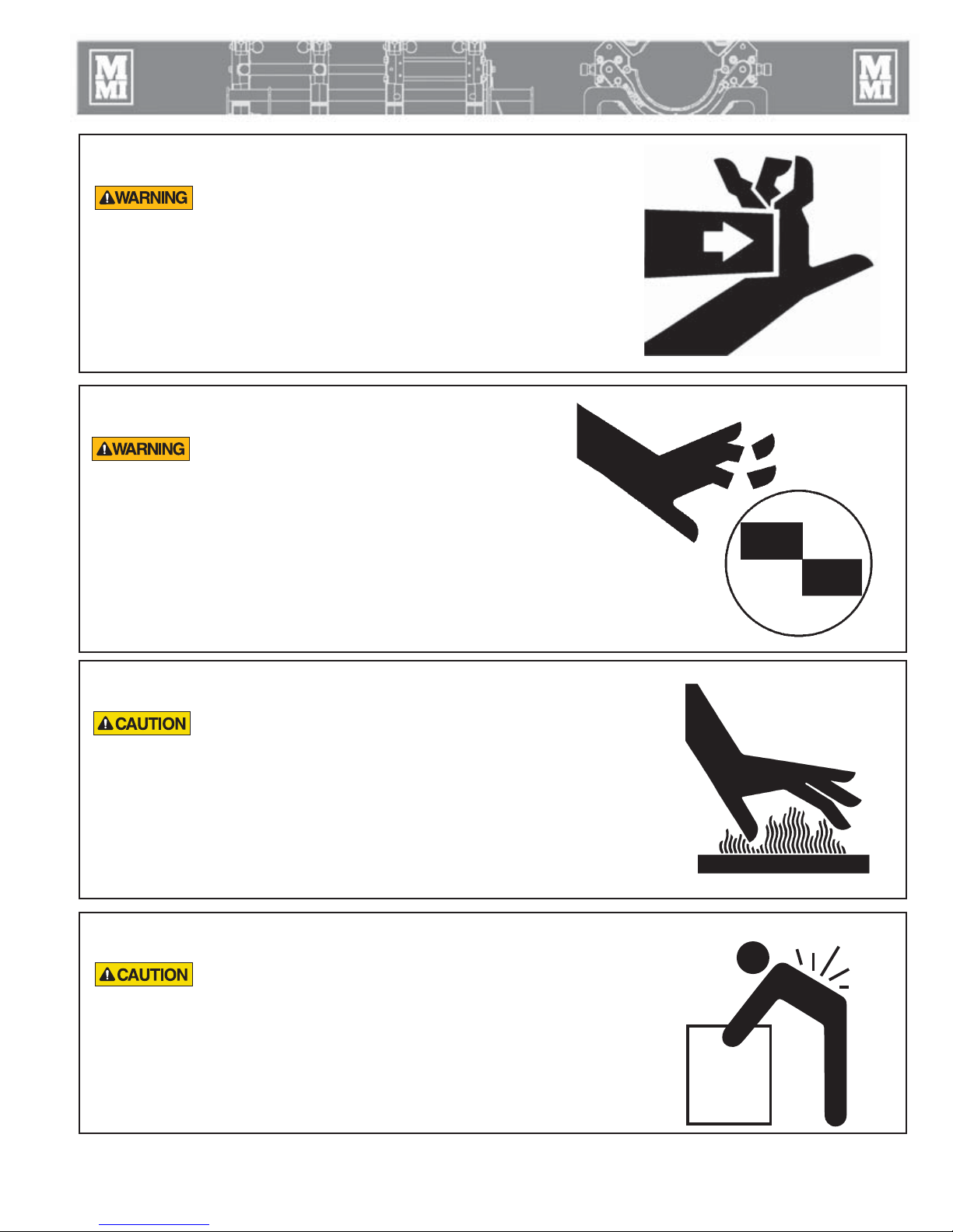
Electrical Safety
Always ensure power cords are properly
grounded. It is important to remember that you
are working in a wet environment with electrical
devices. Proper ground connections help to
minimize the chances of an electric shock.
Frequently inspect electrical cords and unit for damage. Have
damaged components replaced and service performed by a
qualified electrician.
Do not carry electrical devices by the cord.
NOTICE: Disconnect the machine from the power source before
attempting any maintenance or adjustment.
WR00055-4-7-93
WR00025-11-30-92
TX 02947- 4-15-09
1 - 3
Fusion Equipment Safety
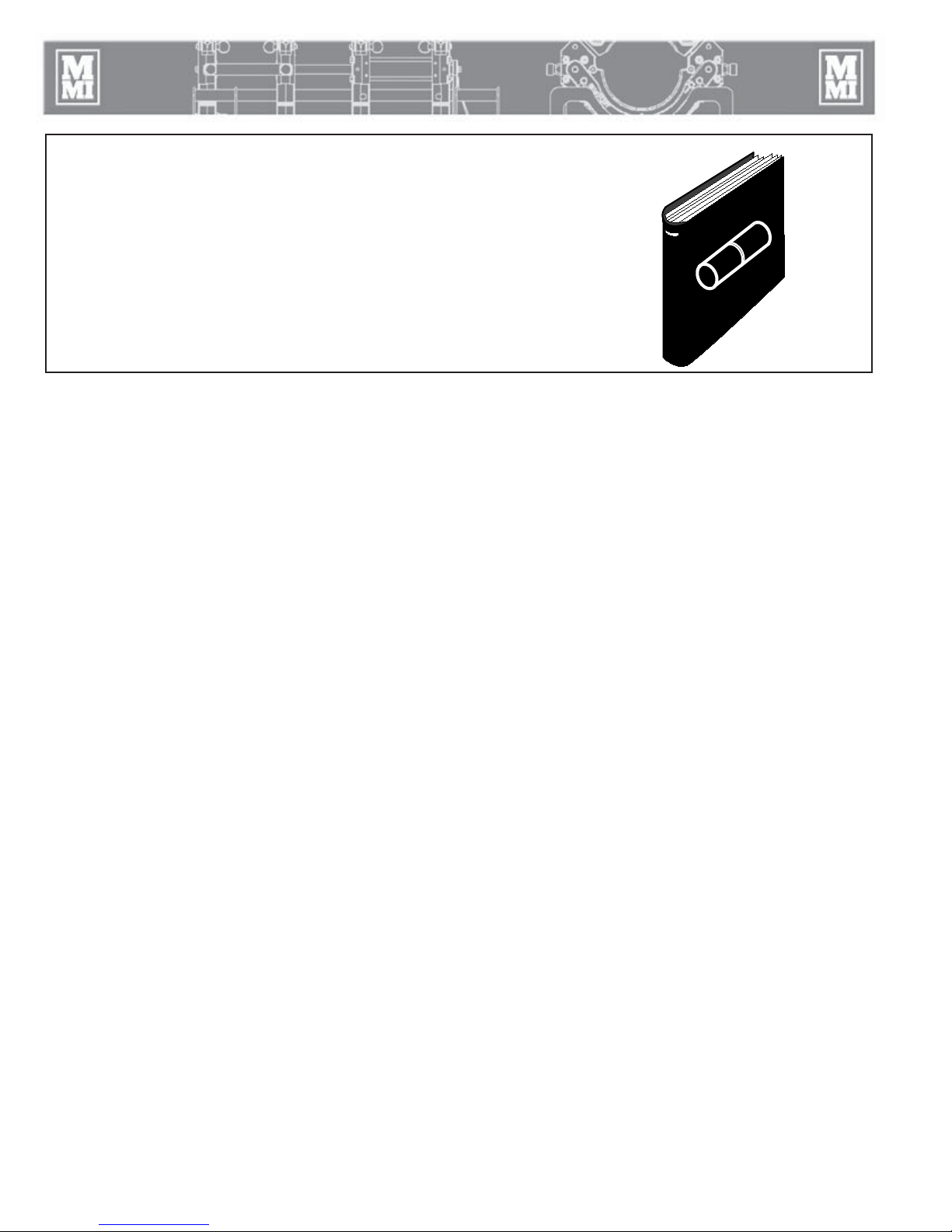
Crush Points
Hydraulically operated jaws are operated under
pressure. Anything caught in the jaws will be
crushed. Keep all body parts out of the jaw area.
Always check pipe alignment with a pencil or
similar object.
TX03091-4-7-10
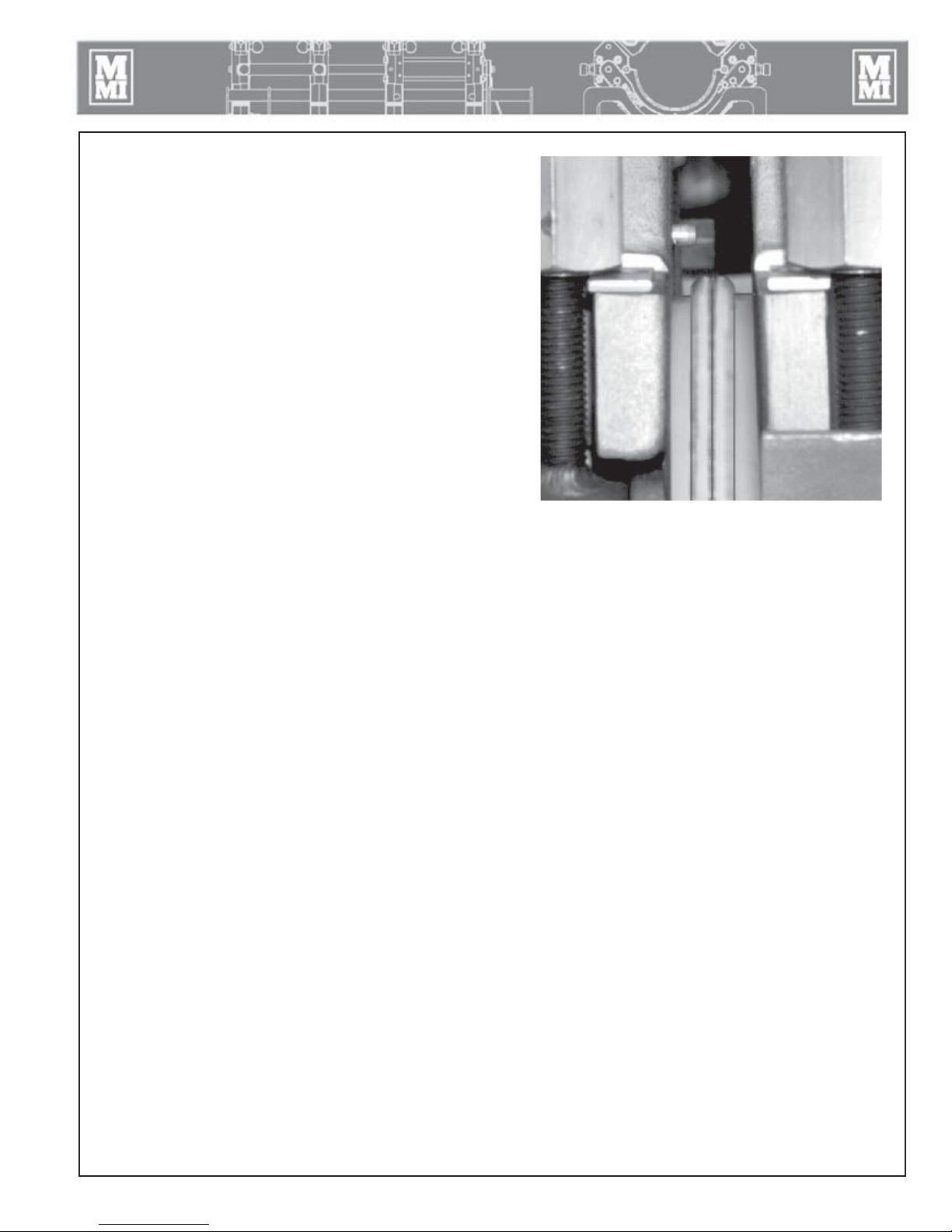
Facer Blades Are Sharp
Facer blades are sharp and can cut. Never attempt
to remove shavings while the facer is running or is
in the facing position between the jaws. Use care
when operating the facer, and when handling the
unit.
NOTICE: Disconnect power from the facer, and remove the facer
blades before attempting any maintenance or adjustment.
NOTICE: Never extend the blade beyond the inner or outer
circumference of the facer.
TX02378-1-24-05
WR00012-12-4-92
WR00073-4-6-93
Heater is Hot
The heater is hot and will burn clothing and skin.
Keep the heater in its insulated heater stand or
blanket when not in use, and use care when
heating the pipe.
NOTICE: Use only a clean nonsynthetic cloth to clean the heater
plates.
TX04244-10-12-10
Heavy Lifting
Components of the DynaMc® EP fusion machines
may be heavy. Using one person to lift may
result in injury. Two people are required to lift
components.
TX04694-04-07-14
WR00030-2-10-93
HeavyLifting
1 - 4
Fusion Equipment Safety
Fusion Procedures
Obtain a copy of the pipe manufacturer's procedures or
appropriate joining standard for the pipe being fused. Follow the
procedure carefully, and adhere to all specified parameters.
NOTICE: Failure to follow pipe manufacturer's procedure
could result in a bad joint. Always follow pipe
manufacturer's procedures.
TX04469-10-24-12
WR00079-1-24-96
1 - 5
Overview
Theory of Heat Fusion
The principle of heat fusion is to heat two surfaces to a
designated temperature, and then fuse them together by
application of force. This pressure causes flow of the melted
materials, which causes mixing and thus fusion. When the
thermoplastic material is heated, the molecular structure is
transformed from a crystalline state into an amorphous condition.
When fusion pressure is applied, the molecules from each
thermoplastic part mix. As the joint cools, the molecules return to
their crystalline form, the original interfaces are gone, and the
fitting and pipe have become one homogeneous unit. A strong,
fully leak tight connection is the result.
The principal operations include:
Clamping The pipe pieces held axially to allow all subsequent
operations to take place.
Facing The pipe ends must be faced to establish clean,
parallel mating surfaces perpendicular to the
centerline of the pipes.
Aligning The pipe ends must be aligned with each other to
minimize mismatch or high-low of the pipe walls.
Heating A melt pattern that penetrates into the pipe must be
formed around both pipe ends.
Joining The melt patterns must be joined with a specified
force. The force must be constant around the interface
area.
Holding The molten joint must be held immobile with a
specified force until adequately cooled.
Inspecting Visually examine the entire circumference of the joint
for compliance with standards established by your
company, customer, industry, federal, state, or local
regulations.
PH00363B-1-4-96
TX04660-03-24-14
2 - 1

Overview
Introduction to the Electric Pump (EP) Fusion
Machines
The McElroy DynaMc® Electric Pump (EP) fusion machines
are hydraulically operated fusion machines designed to fuse
thermoplastic pipe.
When fusing thermoplastic pipe materials, refer to the pipe
manufacturer's fusion procedures or appropriate joining standard.
The 28 model fuses 2" IPS (63mm) through 8" DIPS (225mm)
maximum pipe.
The 412 model fuses 4” IPS (110mm) minimum to 12" DIPS
(340mm) maximum pipe.
The 250 model fuses 63mm (2" IPS) minimum to 250mm (8" DIPS)
maximum pipe.
The 28 Sidewall fuses branch saddles up to 8" DIPS outlet with up to 9 5/8" diameter base on any size main.
All models utilizes the Electric Pump (EP) Hydraulic Power Unit (HPU) to provide hydraulic power to the machines.
TX03092-04-08-14
Carriage Assembly
The DynaMc EP carriage assemblies are available in a 4-Jaw,
2-Jaw and sidewall models and are operated by the DynaMc EP
Hydraulic Power Unit (HPU).
The 4-Jaw EP carriage assembly consists of two fixed jaws and
two hydraulically operated movable jaws bolted to a skid.
For fittings, the inner fixed jaw can be connected to the movable
jaws on the carriage for a 3 movable 1 fixed jaw configuration.
The 2-Jaw EP carriage assembly consists of one fixed jaw and one
hydraulically operated movable jaw bolted to a skid.
The 28 Sidewall EP machine can also be used with the EP HPU.
The 28 Sidewall Ep has one movable jaw and a tailstock that
attaches to the main. The carriage attaches to the main by the use
of chain clamps.
CD00829-4-7-10CD00830-4-7-10CD00828-4-7-10
All EP carriage assemblies use an EP HPU to pressure the
hydraulic cylinders to move the jaws.
TX03097-4-12-10
2 - 2
Overview
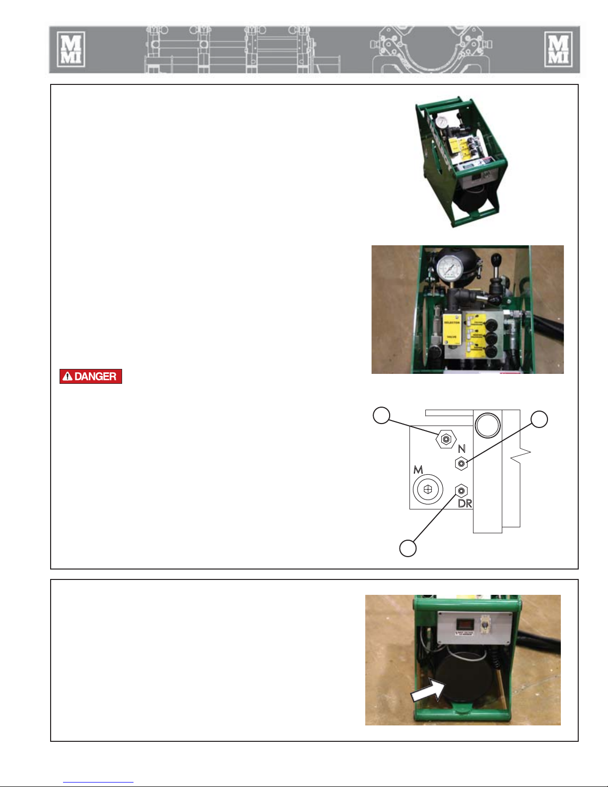
DynaMc EP Hydraulic Power Unit (HPU)
The DynaMc EP HPU consists of three main hydraulic components:
1. Power pack - Consists of a capacitor start electric motor and
gear pump that are submerged in the fluid reservoir to aid in
cooling and reduce noise.
2. Hydraulic accumulator - Allows the power pack to cycle
on and off to meet the demands of the hydraulic system, which
reduces noise and power consumption.
3. Carriage manifold assembly - Standard McElroy design for
familiar operation and common service parts with other McElroy
equipment.
There are two pressure gauges on the HPU. The pressure gauge
above the carriage directional valve displays fusion pressure. The
pressure gauge on the rear left side of the HPU displays main
system pressure, which will fluctuate between approximately 1600
psi - 2900 psi as the power pack cycles on and off.
The main power switch for the HPU is located on the front side of
the electrical box. Next to the power switch is a digital volt meter
that displays incoming voltage to the HPU. On the bottom side of
the electrical box is a motor circuit breaker.
Electric motors are not explosion proof. Operation
of these components in an explosive atmosphere
will result in serious injury or death.
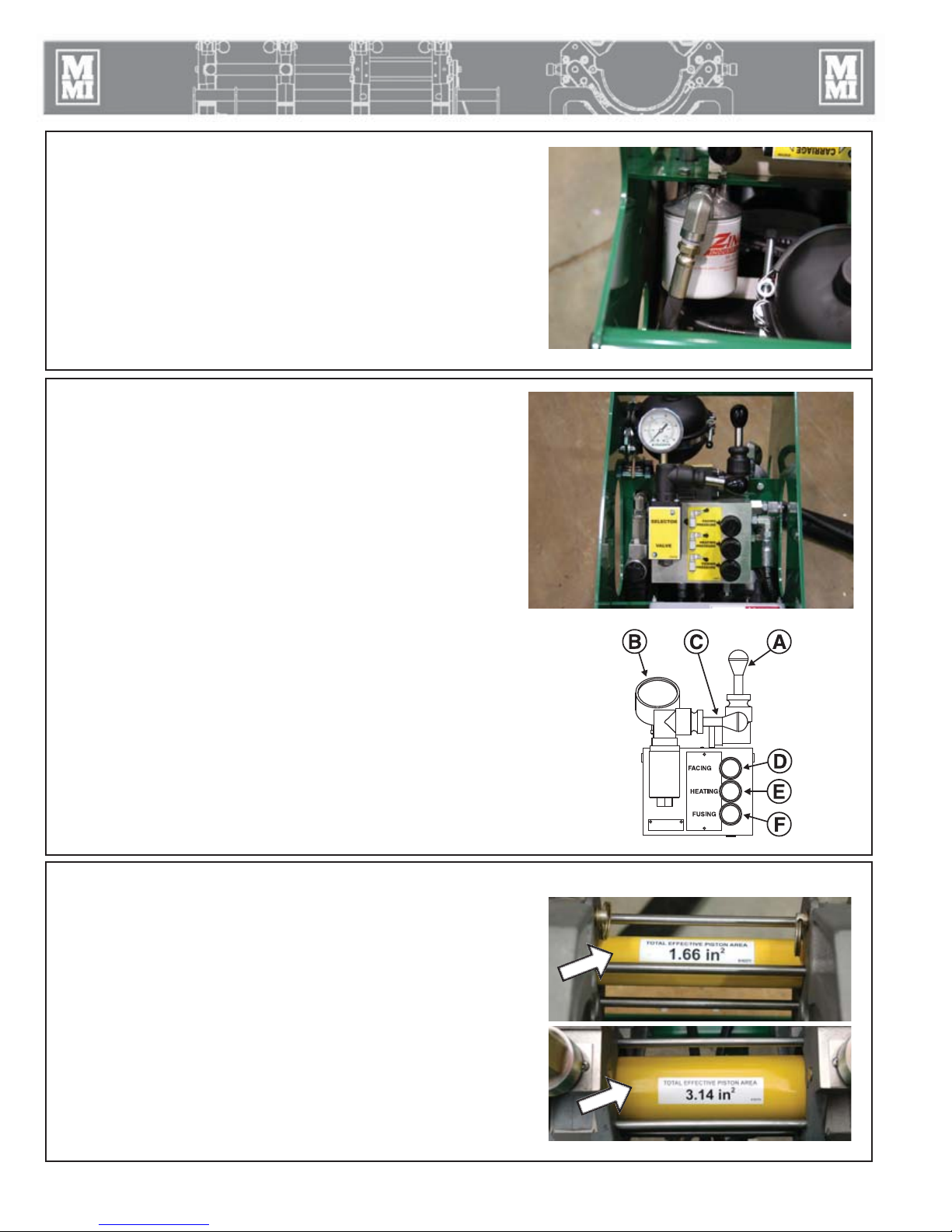
Power Pack Manifold Block
The DynaMc EP HPU's power pack has three factory preset valve
adjustments:
1. Valve "N" is adjusted completely in (clockwise).
2. Valve "DR" is adjusted completely out (counter-clockwise).
3. The non-labeled valve is the main system pressure relief valve that
protects against over-pressurization.
NOTICE: These valves are properly set at McElroy and should never be
re-adjusted.
TX04661-10-5-15
3
PH04146-4-12-10
PH04142-4-12-10CD00831-10-5-15
1
2
Hydraulic Fluid Reservoir
The reservoir is incorporated in the HPU. The fluid level is read
from a dipstick and has a notch to indicate the proper fluid level.
Never allow dirt or other foreign matter to enter the open tank.
Refer to the "Hydraulic Fluids" section of this manual for hydraulic
fluid recommendations.
TX04662-03-24-14
PH04144-4-12-10
2 - 3
Overview
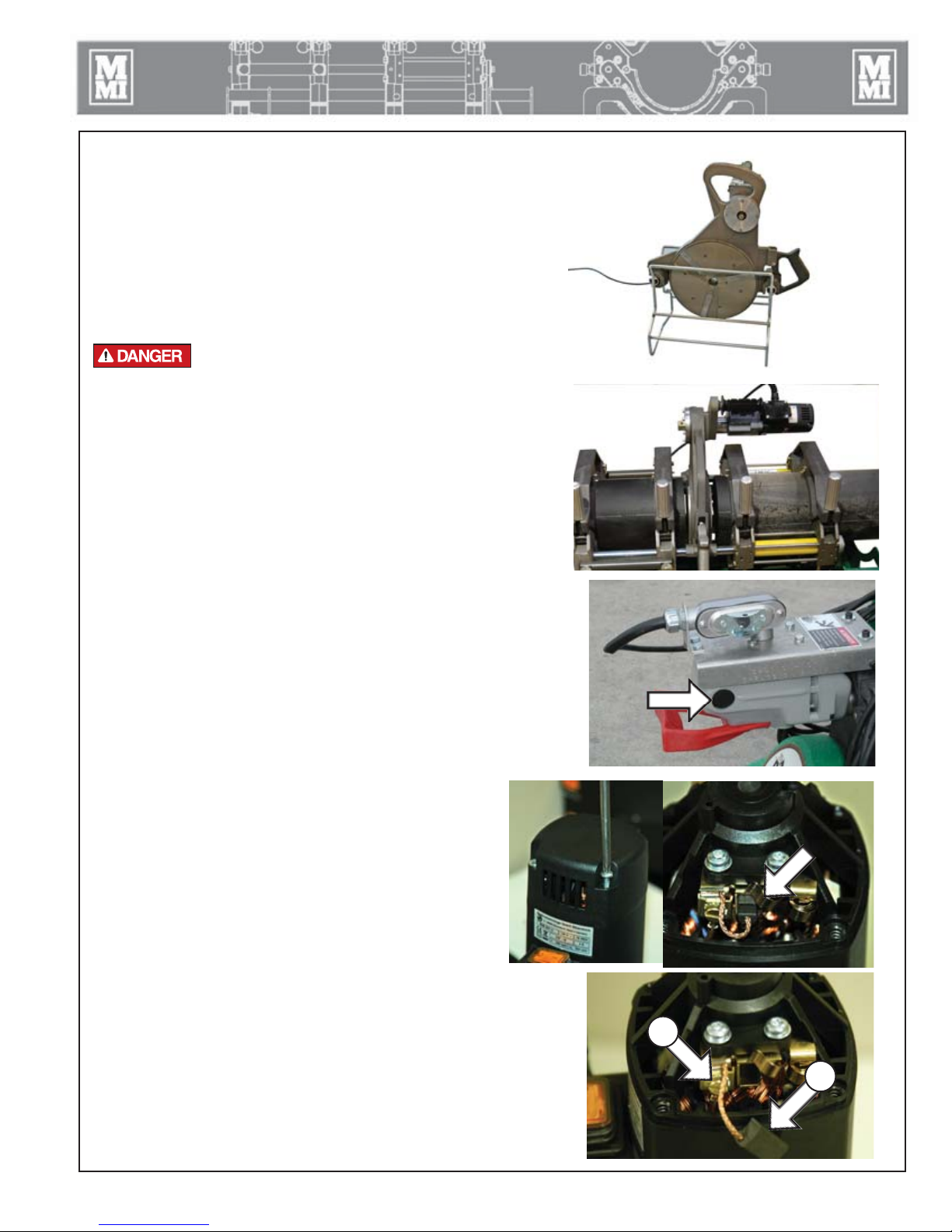
Filter
This machine is equipped with a 10 Micron filter on the return
line.
TX02132-07-08-03
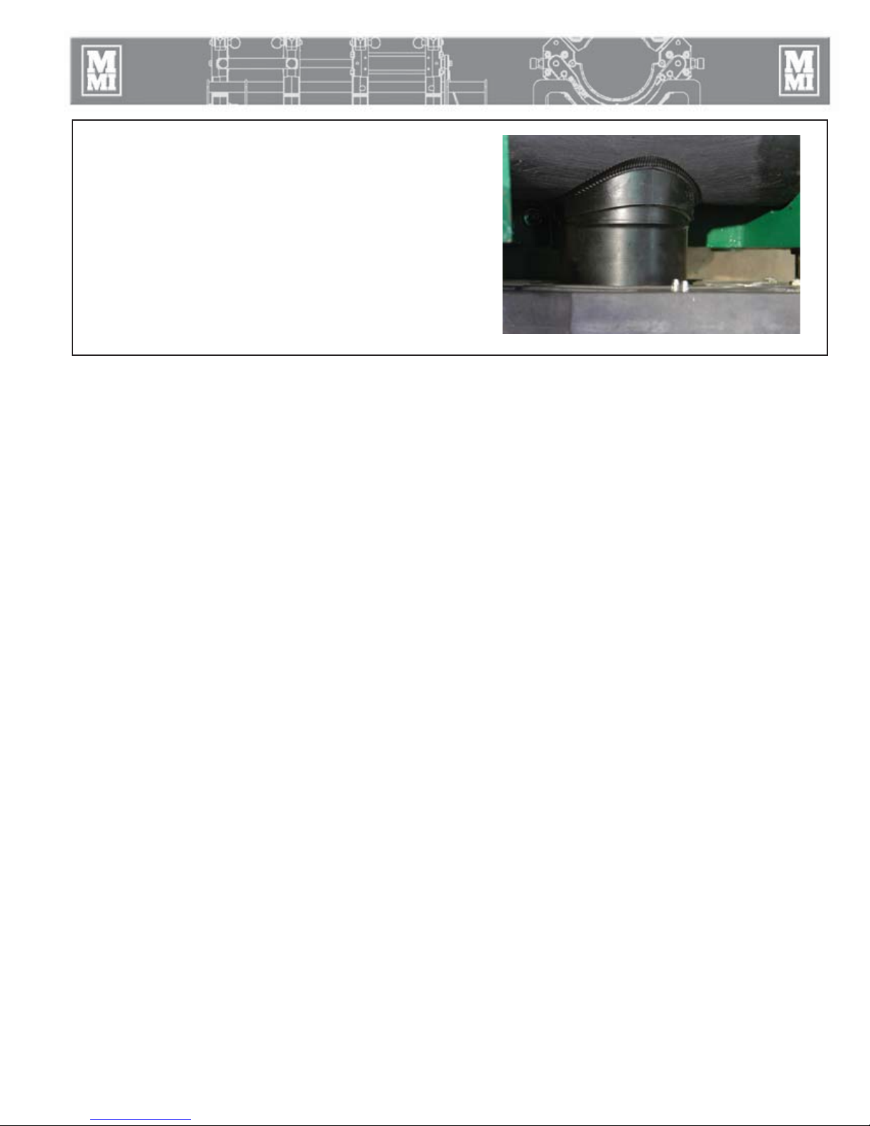
Hydraulic Manifold Block
Mounted on this block are a carriage directional control valve, a
pressure reducing selector valve, three pressure reducing valves,
and a 1500 psi gauge.
A) The carriage control valve, mounted on the top of the
manifold, determines whether the carriage is moving left, right,
or is in neutral.
B) A 1500 psi gauge is mounted on top of the manifold.
C) The selector valve, mounted on the front of the manifold,
selects a reduced pressure from one of the pressure reducing
valves.
Each pressure reducing valve is labeled with a different function:
D) The top valve adjusts facing pressure to a maximum of 400
psi.
E) The middle valve adjusts heating pressure to a maximum of
400 psi.
F) The bottom valve adjusts fusion pressure to a maximum of
1500 psi.
PH04143-4-12-10
PH04142-4-12-10
CD00138A-9-12-94
TX02133-07-08-03
Hydraulic Cylinders
The hydraulic cylinders provide the fusion force which is
dependent on the area of the cylinders.
Consult the "Maintenance" section of this manual for the
procedure to follow when bleeding air from system.
TX03094-4-7-10
PH03949-3-29-10PH04126-4-7-10
2 - 4
Overview
Facer
The facer is of the McElroy rotating planer-block design. The blade
holders each contain multiple cutter blades. The block rotates on
ball bearings and is chain driven (enclosed in lubricant) by an
electric motor. The facer has a release mechanism for quick and
easy removal from the machine. The facer can be inserted from
either side of the carriage.
NOTICE: Never extend the blade beyond the inner or outer
circumference of the facer.
Electric motors are not explosion proof. Operation
of these components in an explosive atmosphere will
result in serious injury or death.
PH03873-3-29-10
Remove brushes on the Milwaukee facer motor:
The armature brushes must be removed from the electric motor when
manually operating in explosive atmospheres. Unscrew the brushes
from both sides of the motor. (Both brushes must be removed).
A 1-1/8" hex shaft allows for manual operation in explosive
atmospheres.
Remove brushes on the Eibenstock facer motor:
The armature brushes must be removed from the electric motor
when manually operating in an explosive atmosphere.
Remove the rear cover of the motor.
Slide the spring clip away from the brush and pull the brush out
(A).
Loosen the brush ground wire (B) and pull the wire loose.
Repeat these steps on the wire on the opposite side.
Store the brushes in a safe location until needed.
A 1-1/8" hex shaft allows for manual operation in an
explosive atmosphere.
PH04099-3-29-10
PH01847-7-25-00
The facer has a handle that latches into place on a guide rod. The
handle must be pulled out to unlatch and remove facer.
The electric facer is symmetrical and can be inserted from either side.
The facer should be stored in the stand when not in use.
NOTICE: Never extend the blade beyond the inner or outer circumference
of the facer.
TX04005-04-07-14
2 - 5
PH04129-4-12-10 PH04130-4-12-10
B
A
PH04130-4-12-10

Overview
Heater
Heater is not explosion proof. Operation of heater
in an explosive atmosphere without necessary safety
precautions will result in serious injury or death.
If operating in an explosive atmosphere, heater should be brought up to
temperature in a safe environment, then unplugged before entering the
explosive atmosphere for fusion.
The heater has a green indicator light which will flash on and off. This
indicates that the controller is operating normally. If the green indicator
is not flashing then the controller may not be operating properly. If this
occurs, disconnect power and have the heater repaired by a McElroy
Authorized Service Center.
The heater temperature is controlled by a microprocessor. It has a red
indicator light on the handle at the bottom of the temperature scale.
When the heater is plugged in and preheating the light glows steadily
until the set temperature is reached. The light then goes off and on slowly
as the heater maintains temperature.
The heater body is not coated. Coated butt fusion heater plates are
available for all butt fusion applications.
NOTICE: The heater should never be used without butt fusion heater plates
installed.
To prevent a build-up of plastic pipe residue from accumulating on the
heater plates (loss of surface temperature and pipe sticking may result),
the heater plates should be cleaned with a nonsynthetic cloth before every
fusion joint.
TX02981-01-03-14
PH03874-3-29-10
PH02314-4-24-02
Insulated Heater Stand
The heater should always be stored in the insulated heater stand
for protection of the operator and to minimize heat loss and risk of
mechanical damage.
The heater is hot and will burn clothing and skin.
Keep the heater in its insulated heater stand or
blanket when not in use, and use care when
heating the pipe.
TX04664-03-24-14
2 - 6
PH03874-3-29-10

Overview
Stripper Bar
The heater stripper bar can be attached to the heater to assist in
separating the heater from the molten pipe. Refer to the instruction
sheet packaged with the stripper bar for assembly instructions.
TX03095-4-7-10
Carriage Shut-off Valve
A shut-off valve is installed on the carriage. When it is closed, the
operator at the HPU can not move the carriage.
PH04127-4-12-10
OPEN
TX04048-4-12-10
CLOSED
Clamp Knobs
Clamp knobs are equipped with a thrust bearing, which permits
the operator to develop high clamping forces with minimal effort.
TX03099-4-12-10
PH04133-4-12-10
PH03895-3-29-10
2 - 7

Butt Fusion Procedure
Read Before Operating
Before operating this machine, please read this manual
thoroughly, and keep a copy with the machine for future
reference.
When fusing thermoplastic pipe materials, refer to the pipe
manufacturer's suggested procedures or appropriate joining
standard.
TX04688-03-25-14
Check Fluid Level
Before connecting to power and with the machine off,
unscrew the dipstick and check the fluid level. The fluid
level should be within ± 0.25" of the notch of the dipstick.
IMPORTANT: Ensure HPU is on a level surface. Unscrew the
dipstick and wipe clean with a lint-free cloth. Screw dipstick
in completely then remove to check fluid level.
Refer to the "Hydraulic Fluids" section of this manual for
hydraulic fluid recommendations.
STOP-12-22-92
PH04136-4-12-10PH04145-4-12-10
TX04000-03-24-14-
Connecting to Power
All electrical equipment and power sources must
be located in a non-explosive atmosphere. Failure
to do so will result in serious injury or death.
Each device must be connected to a source rated for each device's
power requirements. Each device has a plate or label with the
device's power requirements.
Consult generator sizing form in the back of this manual to
determine the proper size generator to power all electrical
equipment.
PH04132-4-12-10PH03874-4-12-10PH04141-4-12-10
FACER
HEATER
TX04001-03-24-14
HPU
3 - 1

Butt Fusion Procedure
Prepare Heater
Heater is not explosion proof. Operation of
heater in an explosive atmosphere without
necessary safety precautions will result in serious
injury or death.
If operating in an explosive atmosphere, heater should be brought
up to temperature in a safe environment, then unplugged before
entering the explosive atmosphere for fusion.
Install butt fusion heater plates.
NOTICE: The heater should never be used without butt fusion
heater plates installed. Refer to the "Maintenance" section of this
manual for installation procedure.
Place heater in insulated heater stand.
Plug heater into a proper power source.
Allow heater to warm-up to operating temperature.
Refer to the "Maintenance" section of this manual for instructions
on how to adjust heater temperature.
PH03874-3-29-10
PH00420-11-1-94
TX02310-03-24-14
Pipe Supports
Low profile rollers are recommended for proper pipe alignment
with the jaws
TX04002-4-12-10
Install Clamping Inserts
Select and install appropriate clamping inserts for the pipe size
that is being fused.
PH03879-3-29-10
PH00304-9-24-93
TX01310-4-1-97
3 - 2

Butt Fusion Procedure
Hydraulic Power Unit (HPU)
Electric motors are not explosion proof. Operation
of these components in an explosive atmosphere
will result in serious injury or death.
Locate HPU in a safe environment. Plug the electrical cord into a
proper power source.
Turn on main power switch and note pressure at the system
pressure gauge.
PH04140-4-12-10
PH04138-4-12-10
TX04003-03-24-14
3 - 3

Butt Fusion Procedure
Facer
Electric motors are not explosion proof. Operation
of these components in a hazardous environment
without necessary safety precautions will result in
serious injury and death.
Ensure facer power switch is in the off position.
Connect facer to proper power source.
Don't turn on facer until ready to face.
Remove brushes on the Milwaukee facer motor:
The armature brushes must be removed from the electric motor
when manually operating in a hazardous condition. Unscrew
the brushes from both sides of the motor. (Both brushes must be
removed). A 1-1/8" hex shaft allows for manual operation in
hazardous conditions.
PH04125-4-12-10
PH01847-7-25-00PH04129-4-12-10PH04130-4-12-10PH04130-4-12-10
Remove brushes on the Eibenstock facer motor:
The armature brushes must be removed from the electric motor
when manually operating in a hazardous condition.
Remove the rear cover of the motor.
Slide the spring clip away from the brush and pull the brush out
(A).
Loosen the brush ground wire (B) and pull the wire loose.
Repeat these steps on the wire on the opposite side.
Store the brushes in a safe location until needed.
A 1-1/8" hex shaft allows for manual operation in hazardous
conditions.
B
TX04004-04-07-14
A
3 - 4

Butt Fusion Procedure
Hydraulic Pressure
The pressure gauge above the manifold block indicates the pressure
at the carriage control valve. The pressure shown on the gauge is
determined by the position of the selector valve and the pressure setting
of the selected pressure reducing valve.
B
A
C
D
A - Carriage Control Valve
B - Pressure Gauge
C - Pressure Selector Valve
D - Pressure Reducing Valves (3)
PH04140-4-12-10
TX04052-4-12-10
3 - 5

Butt Fusion Procedure
Jaw Configuration
The DynaMc EP 4 jaw machines can be configured to a 2
movable/2 fixed jaw configuration or a 3 movable/1 fixed jaw
configuration. This will allow work in close proximity to ells and
tees without the removal of the outer jaw.
To change to the 3 movable/1 fixed jaw configuration:
Unscrew the knobs on the jaw braces and remove the braces.
Align the brace between the middle 2 jaws. The carriage may
have to be moved to align the brace. Attach the brace with the
knobs to secure them in place.
To change to the 2 movable/2 fixed jaw configuration:
Unscrew the knobs on the jaw braces and remove the braces.
Align the brace between the outer fixed jaw and adjacent jaw.
The carriage may have to be moved to align the brace. A block of
wood should be used on both sides across the guide rods to push
the adjacent jaw with the movable jaws to align with the outer
fixed jaw. Attach the brace with the knobs to secure them in place.
2 Movable/2 Fixed Jaw Configuration
PH04094-3-29-10PH04093-3-29-10PH04134-4-12-10
3 Movable/1 Fixed Jaw Configuration
TX04006-4-12-10
Loading Pipe Into Machine
Clean the inside and outside of pipe ends that are to be fused.
Open the upper jaws and insert pipe in each pair of jaws with
applicable inserts installed. Let the ends of the pipe protrude past
the face of the jaws .75" for model 28 and 1.25" for model
250/412.
Move the facer into place. With the carriage control valve lever,
move the carriage toward the fixed jaws while watching the gap
at each end of the facer stops. When the pipe is in contact with
the facer, this gap indicates the amount of material that will be
trimmed from the pipe end. Assure sufficient material will be
removed for a complete face off.
TX04038-04-07-14
PH04098-3-29-10
PH04099-3-29-10
3 - 6

Butt Fusion Procedure
Clamp the Pipe
Tighten the clamp knobs on the outside jaws to prevent pipe from
slipping. Hand tighten the inside clamp knobs to allow for HI/LO
adjustment.
The clamp knobs are equipped with a ball thrust bearing, which
permit the operator to develop high clamp forces with minimal
effort.
NOTICE: When clamping, do not over-tighten the clamp knobs
because machine damage can result. Check to see if there is
space between the upper and lower jaws. If the two jaws are
touching, do not continue to tighten.
TX04007-4-12-10
Begin Facing
Move the carriage to the right.
Turn on the facer.
Assure the selector valve handle is up in the facing position.
Move the carriage control valve to the left.
If the facer stalls, adjust the facing pressure so the facer continues to
cut.
Let the carriage bottom out on facer stops.
Allow the facer to run for several revolutions to ensure that there
are no chips hanging on the end of the pipe.
Turn facer off.
PH04135-4-12-10
PH04125-4-5-10
TX04008-4-12-10
PH04107-3-29-10
3 - 7

Butt Fusion Procedure
After Facing
Move the carriage control valve to the right to open the carriage.
Release the handle lock, and lift the facer out.
Close carriage shut off valve.
Jaws are operated hydraulically by a remote operator. Anything
caught in the jaws will be crushed. Always communicate clearly
with the second operator and use the carriage shut off valve to
lock out jaw motion.
Remove chips from pipe ends.
Do not touch faced pipe ends.
Inspect both pipe ends for complete face off. If the face off is
incomplete, return to Loading Pipe into Machine.
Open shut off valve.
PH04100-3-29-10
TX04040-4-12-10
3 - 8

Butt Fusion Procedure
Determine Drag Pressure
Drag pressure should be determined using the following
procedure:
Move the carriage so that the faced pipe ends are
approximately 1" apart.
Shift the carriage control valve to the middle (neutral) position.
Select the heating mode, and adjust the middle pressure
reducing valve to its lowest pressure by turning the valve
completely counterclockwise.
Shift the carriage control valve to the left.
Gradually increase the pressure by turning the valve clockwise.
Increase the pressure until the carriage moves.
Quickly reduce the heating pressure valve counterclockwise
until the carriage is just barely moving.
Record this actual drag pressure.
B
A
C
D
A - Carriage Control Valve
B - Pressure Gauge
C - Pressure Selector Valve
D - Pressure Reducing Valves (3)
PH04140-4-12-10
TX03023-8-19-09
Calculate Fusion Pressure
With the selector valve in the down position, the fusion pressure
can be set.
The theoretical fusion pressure can be calculated using the
enclosed fusion pressure calculator. Always add drag pressure to
the theoretical fusion pressure.
Gauge (Fusion) Pressure = Theoretical Fusion Pressure + Drag
Pressure
TX03024-8-19-09
Check for Slippage
Bring the pipe ends together under fusion pressure to check for
slippage. If slippage occurs, return to Loading Pipe into Machine.
TX00971-5-31-96
PH04128-4-12-10 PH04004-8-25-09
3 - 9

Butt Fusion Procedure
Check Alignment
Close the carriage until the ends of pipe butt together.
Check pipe joint for proper alignment.
Do not use finger to check for HI/LO
(misalignment). The unit is under pressure, and
slippage could result in crushed fingers. Always
keep hands clear of the jaw area.
If pipe is not lined up, tighten the high side jaw to bring into
alignment.
IMPORTANT: Always tighten the side that is higher, never loosen
the low side.
When the pipe is properly aligned tighten outside clamps to insure
against slippage.
Ensure there is no unacceptable gap between the pipe ends. If
there is an unacceptable gap, reinsert facer and reface.
NOTICE: When clamping, do not over-tighten the clamp knobs
because machine damage can result. Check to see if there is
space between the upper and lower jaws. If the two jaws are
touching, do not continue to tighten.
PH00366-9-12-94
PH00357-9-12-94
TX04010-03-24-14
Position Carriage for Heater Insertion
Move carriage to the right to open a gap large enough to insert
the heater.
NOTICE: Do not open a gap too large as this could damage the
heater stripper bar.
TX04009-4-12-10
PH00323-9-25-93
PH04100-3-29-10
3 - 10

Butt Fusion Procedure
Check Heater Temperature
NOTICE: Incorrect heating temperature can result in
questionable fusion joints. Check heater plates
periodically with a pyrometer and make necessary
adjustments.
Refer to the "Maintenance" section of this manual for instructions
how to adjust heater temperature.
Check heater surface temperature with a pyrometer.
Refer to the pipe manufacturer's recommendations or appropriate
joining standard for proper heater temperature.
IMPORTANT: The dial thermometer on the heater indicates internal
temperature which varies from the actual surface temperature.
The dial thermometer can be used as reference once the surface
temperature has been verified and is never a substitute for actual
surface temperature.
WR00077-4-16-93
PH00420-11-1-94
TX04011-4-12-10
Select the Fusion Position
Move selector valve handle down to the fusing position.
TX00376 -9-15-94
CD00138E-9-12-94
3 - 11

Butt Fusion Procedure
Inserting Heater
The heater is not explosion proof. Operation
of heater in an explosive atmosphere without
necessary safety precautions will result in serious
injury or death.
If operating in an explosive atmosphere, heater should be brought
up to temperature in a safe environment, then unplugged before
entering the explosive atmosphere for fusion.
Use a clean non-synthetic cloth to clean the butt fusion heater
adapter surfaces.
Verify heater temperature by noting the reading on the dial
thermometer.
Insert heater between the pipe ends.
PH03875-3-29-10
PH04101-3-29-10
TX04050-03-24-14
Heating the Pipe
A) Verify that the selector valve is in the fusion position.
B) Close carriage to bring pipe ends in contact with the
heater.
C) Move selector valve to middle (heating mode) position.
D) If heating pressure is not required by pipe manufacturer's
recommendation or appropriate joining standard, or
opposing forces are not great enough to move the
carriage away from the heater, shift the carriage control
valve to neutral.
A
B DC
CD00140-9-12-94
PH04102-3-29-10
TX04012-03-24-14
3 - 12

Butt Fusion Procedure
Fusing the Pipe
NOTICE: Failure to follow pipe manufacturer's fusion
procedures may result in a bad joint.
After following the pipe manufacturer's suggested heating
procedure:
A) Shift carriage control valve to neutral position, if it is not
already in that position.
B) Shift the selector valve down to fusion position.
C) Open the carriage just enough to remove the heater.
Quickly remove the heater and inspect pipe ends for
appropriate melt.
D) Quickly close the carriage, bringing the pipe ends together
under the pipe manufacturer's recommended pressure.
CD00141B-9-12-94 CD00141A-9-12-94
Allow joint to cool under pressure.
Visually examine the entire circumference of the joint for
compliance with standards established by your company,
customer, industry, federal, state, or local regulations.
TX04013-03-24-14
Opening Jaws
After the joint has cooled for the pipe manufacturer's
recommended time or appropriate joining standard, shift the
carriage control valve to the neutral position.
Loosen all clamp knobs, and open the carriage.
Open the all jaws
PH04103-3-29-10
PH04104-3-29-10
TX04014-4-12-10
3 - 13

Butt Fusion Procedure
Position Pipe for Next Joint
Move the fusion machine to end of pipe, or pull the pipe through
the jaws until the end of the pipe is protruding .75" for 28 and
1.25" for 250/412 past the fixed jaw.
TX04015-4-12-10
Install Next Piece of Pipe
Move the carriage control valve and open the carriage completely.
Insert a new piece of pipe in movable jaws and repeat all
previous procedures.
PH04104-3-29-10
PH04098-3-29-10
TX04016-4-12-10
3 - 14

Special Operations - In Ditch
Remove Carriage from Skid
The carriage can be removed from the base for close quarters in
ditch fusion.
To remove the carriage:
A) Remove the rod out of the carriage and through the opening
on the base.
B) Slide the carriage forward to release it from the back of the
base.
Lift the carriage away from the base.
B
A
PH04124-4-5-10 PH03900-4-15-09PH04123-4-5-10
TX02967-4-15-09
4 - 1

Special Operations - In Ditch
Lower the Carriage into Ditch
Lowering carriage without the skid
Open the jaws.
Attach lifting strap (not included) to carriage base.
Lift carriage assembly and lower into ditch.
Lower carriage on top of the pipe and rotate the carriage
underneath the pipe.
Lowering carriage with skid
Attach lifting strap to the carriage skid.
Lift carriage assembly and lower into the ditch.
PH04121-4-5-10PH04120-4-5-10PH04122-4-5-10PH04122-4-5-10
Components of the DynaMc® EP fusion machines
may be heavy. Using one person to lift may
result in injury. Two people are required to lift
components.
Lowering the carriage without skid manually
Open the jaws.
Rotate the carriage on its jaws.
Two person lift the carriage using the carriage base.
Lift carriage assembly and lower into the ditch.
Lowering the carriage with skid manually
Two person lift the carriage assembly using the handles on each
end of the skid.
Lift carriage assembly and lower into the ditch.
TX04017-04-07-14
4 - 2

Special Operations - In Ditch
Removing Top Jaws
If the carriage needs to be hoisted and slid underneath the pipe,
the top jaws may need to be removed.
Loosen all clamp knobs. Take out the detent pins securing the top
jaws and remove the jaws.
TX04018-4-12-10
Clamp Carriage Assembly to Pipe
Position carriage assembly on top of the pipe. Lift pipe and rotate
carriage assembly under pipe.
PH04137-4-12-10
CD00194d-4-5-10CD00194d-4-5-10CD00195d-4-5-10
Rotate carriage assembly around to a normal upright position.
Attach the top jaws if removed and loosely clamp around pipe.
TX04019-4-12-10
4 - 3

Special Operations - In Ditch
Make Fusion Joint
Refer to the "Butt Fusion Procedure" for operating instructions.
After facing operation, remove the facer from ditch.
TX00450-9-16-94
Remove Carriage Assembly from Ditch
Loosen clamp knobs and remove top jaws if needed.
Rotate carriage assembly from under the pipe.
Use one of the recommended lifting methods from "Lower the
Carriage into Ditch" section of this manual to lift the carriage from
the ditch.
Lift carriage assembly from ditch.
PH00363-9-12-94
PH04121-4-5-10
TX04020-4-12-10
Attach Carriage to Skid
Install carriage assembly to the skid. Refer to the "Remove Carriage
from Base" section of this manual and follow instructions in reverse
to attach carriage to skid.
Replace top jaws if removed.
PH04124-4-5-10PH04123-4-5-10
TX04021-4-12-10
4 - 4

Special Operations
- Saddle Fusion Procedure
Saddle Fusion Procedure
The 28 Sidewall fuses branch saddles up to 8" DIPS outlet and
up to a 9-5/8" diameter base on any size main.
IMPORTANT: Optional chain extension kit is available for larger
main sizes.
TX04045-4-12-10
Install Heater Adapters
Heater is not explosion proof. Operation of
heater in an explosive atmosphere without
necessary safety precautions will result in serious
injury and death.
If operating in an explosive atmosphere, heater should be brought
up to temperature in a safe environment, then unplugged before
entering the explosive atmosphere for fusion.
Select appropriate heater and sidewall fusion heater adapters.
Clean heater surfaces and adapter surfaces. Attach the adapters
to the heater.
Place heater in insulated heater blanket.
Plug heater into a proper power source.
PH04108-3-30-10
PH04117-4-5-10PH04118-4-5-10
TX00455-04-07-14
Assure Saddle Will Fit
For branch saddles, a nipple long enough to extend through
the movable jaw may need to be butt fused using a butt fusion
machine and the butt fusion procedures.
TX04022-4-12-10
PH00423-11-1-94
5 - 1

Special Operations
-
Install Clamping Inserts
Select and install appropriate clamping inserts in the movable
jaw.
TX04023-4-12-10
Attach Carriage Assembly to Main
Place the machine on the main.
Place a line bolster on main opposite the carriage assembly if
required.
Position the tailstock chains around the main and lock into the
chain hooks.
Tighten the machine onto the main using the tailstock clamp
knobs.
Saddle Fusion Procedure
PH00304-9-23-93
PH00387-9-21-94
TX04024-4-12-10
Hydraulic Manifold Block
Mounted on this block are a carriage directional control valve, a
pressure reducing selector valve, three pressure reducing valves,
and a 1500 psi gauge.
A) The carriage control valve, mounted on the top of the
manifold, determines whether the carriage is moving left, right,
or is in neutral.
B) A 1500 psi gauge is mounted on top of the manifold.
C) The selector valve, mounted on the front of the manifold,
selects a reduced pressure from one of the pressure reducing
valves.
Each pressure reducing valve is labeled with a different function.
IMPORTANT: These functions are labeled for standard butt fusion.
For saddle fusion the top valve is used for fusion pressure, the
middle valve for heat/soak pressure and the bottom valve for
initial heat (bead-up) pressure.
D) The top valve adjusts pressure to a maximum of 400 psi.
E) The middle valve adjusts pressure to a maximum of 400 psi.
F) The bottom valve adjusts pressure to a maximum of 1500 psi.
PH04142-4-12-10
CD00138A-9-12-94
TX04051-4-12-10
5 - 2

Special Operations
- Saddle Fusion Procedure
Set Hydraulic Pressure
Check hydraulic pressure. Shift the selector valve to the center
position to set the pressure for heat/soak. With the selector valve
in the down position, the initial heat (bead-up) pressure can be
set. With the selector valve in the top position, the fusion pressure
can be set.
Consult the pipe manufacturer's recommendations or appropriate
joining standard for proper pressures.
TX04025-4-12-10
Clean Surfaces
Use 50 or 60 grit utility cloth or scraping tool
to clean and rough the main to expose fresh
material.
Rough the base of the fitting unless the
manufacturer specifies otherwise.
CD00138B-9-12-94
PH04110-3-30-10PH04111-3-30-10
TX04026-4-12-10
Clamp Fitting
Position the fitting, and bolster if required, loosely in the movable
jaw. Close the carriage to properly position the fitting on the
main. Tighten the clamp knob.
Be sure to allow enough travel for the melt pattern and fusion to
occur (3/4" min.).
TX04027-4-12-10
Test for Slippage
Bring the fitting against the main under initial heat (bead-up)
pressure to insure that no slippage or movement of the main or
fitting occurs.
IMPORTANT: A piece of slightly larger pipe could be used as
a spacer between the saddle base and the movable jaw to
prevent slippage.
PH00399-9-21-94
PH00390-9-21-94
TX04028-4-12-10
5 - 3

Special Operations
- Saddle Fusion Procedure
Prepare Heater
NOTICE: Incorrect heating temperature can result in
questionable fusion joints. Check heater plates
periodically with a pyrometer and make necessary
adjustments.
Refer to the "Maintenance" section of this manual for instructions
how to adjust heater temperature.
Check heater surface temperature with a pyrometer.
Refer to the pipe manufacturer's recommendations or appropriate
joining standard for proper heater temperature.
IMPORTANT: The dial thermometer on the heater indicates internal
temperature which varies from the actual surface temperature.
The dial thermometer can be used as reference once the surface
temperature has been verified and is never a substitute for actual
surface temperature.
PH04118-4-5-10
PH00420-11-1-94
TX04011-4-12-10
Inserting Heater
The heater is not explosion proof. Operation
of heater in an explosive atmosphere without
necessary safety precautions will result in serious
injury or death.
If operating in an explosive atmosphere, heater should be brought
up to temperature in a safe environment, then unplugged before
entering the explosive atmosphere for fusion.
Use a clean nonsynthetic cloth to clean the butt fusion heater
adapter surfaces.
Verify heater temperature by noting the reading on the dial
thermometer.
Place the heater on the main centered beneath the fitting base,
and then place the Flexible Heat Shield between the heating tool
and the fitting base. (This step usually requires an assistant to
handle the Flexible Heat Shield).
IMPORTANT: A heat shield may not be required for fittings 3" and
smaller.
PH04118-4-5-10
TX04041-04-07-14
5 - 4

Special Operations
- Saddle Fusion Procedure
Heat Pipe and Fitting
Move selector valve to the bottom position.
Move the fitting against the Flexible Heat Shield under bead-
up pressure, and observe melt bead formation on the main all
around the heater faces. When a melt bead is first visible on
the main all around the heating tool faces, in a quick continuous
motion, open the carriage slightly and remove the Flexible Heat
Shield.
Move the fitting against the heater face and start the heat time.
When a melt bead is first visible all around the fitting base
(usually about 3 to 5 seconds) immediately move the selector
valve to the middle position to reduce pressure to the heat soak
pressure (usually drag). Wait for the pressure to drop to drag
pressure then shift the control valve to neutral. Maintain the
heat soak pressure according to the pipe fitting manufacturer's
recommendations or appropriate joining standard.
PH04114-3-30-10
TX04042-4-12-10
Remove Heater
Shift the carriage control valve to neutral and move the selector
valve to the top position. Open the carriage just enough to
remove the heater.
Remove the heater.
Quickly check for a complete and even melt pattern on the pipe
main and fitting.
TX04029-4-12-10
Fuse Fitting to Pipe
Quickly close the carriage bringing the fitting and main together
under the pipe manufacturer's recommended pressure or
appropriate joining standard.
PH04115-3-30-10
PH04116-3-30-10
TX04030-4-12-10
5 - 5
Special Operations
- Saddle Fusion Procedure
Allow Joint to Cool
Allow the joint to cool under pressure as specified by the pipe
manufacturer's recommendation or appropriate joining standard.
To maintain fusion pressure during cooling, the carriage control
valve must be positioned in the left hand direction.
TX04043-4-12-10
PH04116-3-30-10
5 - 6

Special Operations
- Lifting Fusion Machine
Lifting Safety
Follow all applicable federal, state, local, and industry specific
regulations when lifting.
Safety warnings:
1. Do not exceed rated load or lift loads greater than the rated
load rating of the lifting device.
2. Do not operate a damaged or malfunctioning lifting device.
3. Do not lift persons.
4. Do not lift a suspended load over persons.
5. Do not leave a suspended load unattended.
6. Do not remove or obscure warning labels.
7. Read and understand the operator’s manual before using the
device.
8. Stay clear of the suspended load.
9. Lift loads only as high as necessary.
10. Do not alter or modify the lifting device.
11. Employ generally accepted safe lifting practices.
12. Do not shock or impact load the lifting device.
SAFE1st- 12- 14- 92
WR00014-3-8-93
TX04047-04-07-14
Manual Lifting
There are two hand holds on the operator side of the machine
and a long hand hold along the opposite side of the machine.
The fusion carriages are a two person lift and should not be lifted
alone.
The Hydraulic Power Unit (HPU) is a two person lift and should not
be lifted alone.
Components of the DynaMc® EP fusion machines
may be heavy. Using one person to lift may
result in injury. Two people are required to lift
components.
TX04031-04-07-14
PH02497-07-11-03
6 - 1

Special Operations
- Lifting Fusion Machine
Powered Lifting
Powered lifting requires a hoist or lifting equipment of proper
lifting capacity to lift the machine.
Close jaws and tighten the jaw clamp knobs on each jaw.
Attach a properly rated lifting strap through the center of the
movable jaws and a strap through the center of the fixed jaws.
For 2 Jaw machines, attach a properly rated lifting strap through
the center of each jaw.
Use proper overhead rigging and equipment of adequate load
rating to lift the fusion unit.
TX04032-4-12-10
PH04119-4-5-10
6 - 2

Maintenance
Preventative Maintenance
To insure optimum performance, the machine must be kept clean
and well maintained.
With reasonable care, this machine will give years of service.
Therefore, it is important that a regular schedule of preventive
maintenance be kept.
Store machine inside, out of the weather, whenever possible.
TX00428-8-10-95
Washing the Machine
The machine should be cleaned as needed with a soap and water
wash.
CD00142-11-2-94
PH04096-3-29-10
TX00429-9-15-94
Check Hydraulic Fluid
Before connecting to power and with the machine off,
unscrew the dipstick and check the fluid level. The fluid
level should be within ± 0.25" of the notch of the dipstick.
IMPORTANT: Ensure HPU is on a level surface. Unscrew
the dipstick and wipe clean with a lint-free cloth. Screw
dipstick in completely then remove to check fluid level.
Refer to the "Hydraulic Fluids" section of this manual for
hydraulic fluid recommendations.
TX04000-03-24-14
Change Hydraulic Fluid and Filter
The hydraulic filter should be replaced every year.
The hydraulic fluid should be replaced every two years.
Fill the reservoir from a clean container.
Refer to the "Hydraulic Fluids" section of this manual for hydraulic oil
recommendations.
PH04136-4-12-10PH04145-4-12-10
PH04143-4-12-10
TX03075-2-4-10
7 - 1

Maintenance
Accumulator Charge
The precharge should be checked every 6 months.
The accumulator must be charged by a qualified hydraulic service
facility to a nitrogen precharge of 500 psi.
An approximate amount of charge can be noted on the system
pressure gauge when the HPU is turned on. When the HPU is
turned on, the gauge will jump to a pressure before continuing
to build pressure. The initial jump in pressure will indicate the
approximate pressure of the precharge.
NOTICE: The precharge should be checked/maintained by a
qualified hydraulics repair tech.
TX04695-04-08-14
Check Pressure Gauges
Both pressure gauges should be checked daily.
The gauges should read zero when the unit is not
running.
Damaged gauges should be replaced.
TX04033-4-12-10
Clean Jaws and Inserts
To prevent slippage and insure proper alignment, the jaws and
inserts must be clean.
Clean the jaws and inserts of any dirt or residual material using
a stiff-bristled brush.
TX00433-9-15-94
Clean Thrust Bearings
PH04139-4-12-10 PH05177-04-08-14PH04138-4-12-10
PH03894-3-29-10PH03895-3-29-10
The thrust bearings located in the clamp knobs must turn freely.
Wash the clamp knob bearing assembly with a solvent, and then
lubricate with 30W or lighter oil.
TX00434-9-13-94
7 - 2

Maintenance
Clean Eyebolt Threads
Keep the clamp knob eyebolt threads brushed clean.
TX00435-9-13-94
Clean the Clamping Chains
On the 28 sidewall unit, clean the tailstock chains as needed.
Clean using a stiff-bristled brush and oil generously. Wipe
away any excess oil.
PH03895-3-29-10
PH04109-4-5-10
TX04034-4-12-10
Fasteners Must Be Tight
Check all nuts, bolts, and snap rings to make certain they are
secure and in place.
TX00437-9-13-94
Facer Blades
Blades bolt directly to the blade holder and should be inspected
for damage and sharpness.
Dull or chipped blades must be replaced.
NOTICE: Never extend the blade beyond the inner or outer
circumference of the facer.
PH00433-11-1-94
PH03896-3-29-10
TX02475-3-29-05
7 - 3

Maintenance
Clean Heater Surfaces
The heater faces must be kept clean and free of any plastic build up or
contamination.
Before each fusion joint the heater surfaces must be wiped with a clean,
non-synthetic cloth.
NOTICE: Do not use an abrasive pad or steel wool. Use a non-synthetic
cloth that won't damage surfaces.
TX00440-8-14-08
Bleeding Air From Hydraulic System
The two carriage cylinders have air bleed screws and must be bled
if the system ever runs low on oil or leaks air on inlet side of pump.
Air in the system is indicated when carriage movement becomes
jerky and erratic. To bleed the system, proceed as follows:
For the 28 and 250 machines:
Remove upper jaws & clamping eye bolts from the two movable
clamp jaws to expose the bleed plugs recessed in top of the lower
jaws.
For the 412 machines:
The bleed screws are on the ends of the rod glands.
PH03875-3-29-10
PH03949-3-29-10
Tilt machine so the fixed jaw end is higher than the opposite end.
Move the carriage control valve to close carriage, and move the
carriage to the fixed jaw end.
Loosen the bleed plug on one cylinder next to the fixed jaw.
Hold pressure on the cylinder until no air is indicated and quickly
tighten the plug.
Repeat this operation on the opposite cylinder.
Tilt the machine so the opposite end is higher than the fixed jaw
end. Move the carriage to the end opposite the fixed jaw and
repeat the above procedure on the this end of the cylinders.
TX02975-04-08-14
7 - 4
PH04126-4-7-10

Maintenance
Installing Butt Fusion Heater Plates
The heater body of this assembly is not coated. Coated butt fusion
heater plates are available for all butt fusion applications.
Care should be taken to ensure that the butt fusion heater plates
are seated on the heater body, and that there is no foreign matter
trapped between these surfaces.
IMPORTANT: Do not over tighten the bolts.
The surface of the butt fusion heater plates are coated with an
antistick coating.
TX04035-4-12-10
Adjusting Heater Temperature
Turn knob to desired temperature. Measure the heater surface
temperature with a pyrometer. Any variance must be corrected to the
pyrometer reading.
Loosen setscrew in the knob. Turn knob to point to the same
temperature as the pyrometer. Tighten setscrew in the knob.
Turn knob to desired temperature. Allow heater to stabilize at the new
temperature (5 to 10 minutes) after adjusting.
The thermometer on the heater body indicates internal temperature and
should be used as a reference only.
TX02009-3-13-02
PH03876-3-29-10
PH02313-4-24-02
Heater Indicator Light
The heater has a green indicator light which will flash on and off. This
indicates that the controller is operating normally. If the green indicator
is not flashing then the controller may not be operating properly. If this
occurs, disconnect power and have the heater repaired by an McElroy
Authorized Service Center.
The heater has a red indicator light on the handle at the bottom of the
temperature scale. When the heater is plugged in and preheating the
red light glows steadily until the set temperature is reached. The red
light then goes off and on as the heater maintains temperature.
If the heater is not operating properly, the control will attempt to turn the
heater off and the red indicator light will flash rapidly. If this occurs,
disconnect the power and take it to a McElroy Authorized Service
Center for repair.
TX04036-4-12-10
PH02314 -4-24-02
PH02571-09-16-03
7 - 5

Maintenance Checklist
Fusion Machine Checklist
Item to Check Satisfactory Needs Repair Comments
Repair
UNIT
Machine is clean
All pins and snaprings are in place
All nuts and bolts are tight
All placards and handles are in place
All clamp knobs turn freely
Cords and plugs are in good condition
Oil reservoir is filled to correct level
Machine is free of hydraulic leaks
Hydraulic gauges read correctly
Jaws are properly aligned
Facer operates smoothly
Face-off is square
Inserts fit and pin properly
Carriage and Selector Valves operate smoothly
Pressure Reducing Valves operate in their range
Heater surface is clean and in good condition
Thermometer is in good working order
Surface temperature checked with pyrometer
TX04037-4-12-10
8 - 1

Determining Fusion Pressure
Variable Definitions
O.D. = Outside Diameter
t = Wall Thickness
= 3.1416
SDR = Standard Dimensional Ratio
IFP = Manufacturer’s Recommended
Interfacial Pressure
TEPA = Total Effective Piston Area
Formulas
O.D.
t = ------------
SDR
AREA = (O.D. - t) x t x
FORCE = AREA x IFP
(O.D. - t) × t × × IFP
GAUGE PRESSURE = ----------------------------------------------- + DRAG
TEPA
Example
Pipe Size = 8" IPS
O.D. of Pipe = 8.625
SDR of Pipe = 11
Recommended Interfacial Pressure = 75 PSI
Using a Model 28 Fusion Unit
O.D. 8.625
t = ------------- = --------------- = 0.784
SDR 11
TEPA = 4.710 (From Table)
(O.D. - t) × t × × IFP
GAUGE PRESSURE = ----------------------------------------------- + DRAG
TEPA
Total Effective Piston Areas
Fusion High Force Medium Low Force
Model (Standard) Force (High (Extra High
Velocity) Velocity)
160 - - 0.90
28/250 4.71 - 1.66
412 11.78 6.01 3.14
618 11.78 6.01 3.14
500 - 6.01 3.14
824 29.44 15.32 9.45
1236 29.44 15.32 9.45
1648 31.42 14.14 -
2065 31.42 - -
1600 31.42 14.14 -
(8.625. - .784) × .784 × 3.1416 × 75
GAUGE PRESSURE = -------------------------------------------------------------------------------- + 30 P.S.I. DRAG = 338 PSI
4.710
TX00343-12-9-93
9 - 1
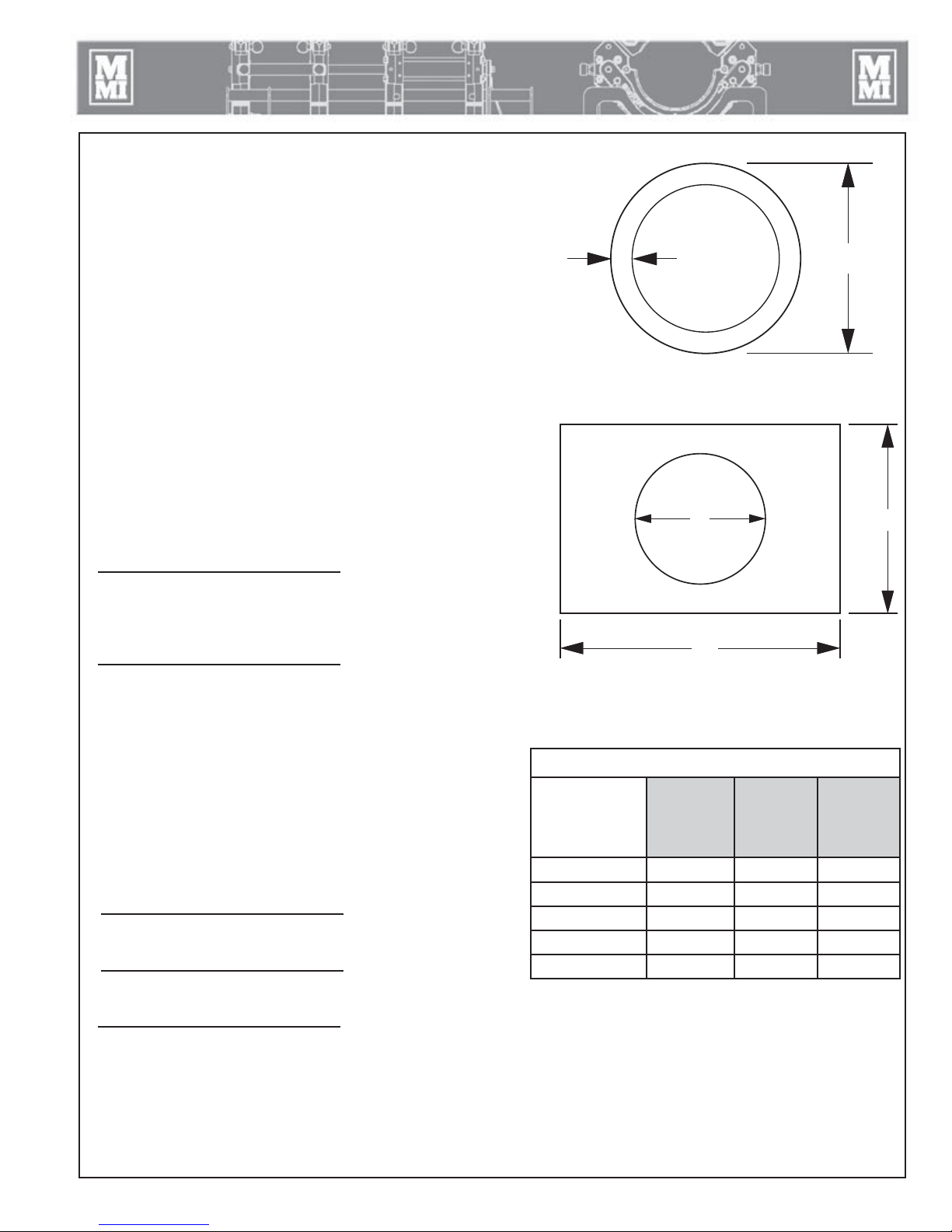
Determining Fusion Pressure - Sidewall
O.D.
t
W
L
d
Variable Definitions
O.D. = Outside Diameter of Base (not branch)
t = Wall Thickness
∏ = 3.1416
SDR = Standard Dimensional Ratio
IFP = Manufacturer’s Recommended Interfacial Pressure
TEPA = Total Effective Piston Area
Formulas
O.D.
t = ------------
SDR
AREA = (O.D. - t) x t x
FORCE = AREA x IFP
IFP = 60 PSI for Bead-up
0 PSI for Heat/Soak
30 PSI for Saddle Fusion
ROUND BASE
BASE
END
ROUND BASE
(O.D. - t ) x t x Π x IFP
TEPA
RECTANGULAR BASE
[ L x W - ( d x d x 0.7854 )] x IFP
TEPA
Example
O.D. of Base = 7.36"
t = 1.10"
DRAG = as measured in PSI (30 PSI for this example)
30 PSI for Saddle Fusion (must calculate for other IFP's also).
Using 28 Combination Unit and calculating the fusion pressure
(O.D. - t ) x t x Π x IFP
TEPA
(7.36 - 1.10 ) x 1.10 x 3.14 x 30
4.71
+ DRAG
+ 30 PSI
RECTANGULAR BASE
Total Effective Piston Areas
Medium
Fusion
Model
Sidewinder 1.00
28 CU 4.71 - 1.66
28 EP Sidewall - - 1.66
18 Sidewall 11.80 - 36 Sidewall 11.00 - -
High Force
(Standard)
Force
(High
Velocity)
Low Force
Extra
High
Velocity
648.66
4.71
Using the same formula substitute the IFP with the IFP appropriate for the process and recalculate for each
Heat Soak Pressure for this example = 30 PSI
Bead-up Pressure for this example = 306 PSI
TX04270-4-7-11
+ 30 PSI = 168 PSI Fusion Pressure
9 - 2

Hydraulic Fluids
Hydraulic Fluids
The use of proper hydraulic fluid is mandatory to achieve maximum performance and machine life. Use a clean, high
quality, anti-wear hydraulic fluid with a viscosity index (VI) of 135 minimum. It should have a maximum viscosity of
500 cSt (2000 SSU) at startup (ambient temperature) and a minimum viscosity of 13 cSt (65 SSU) at the maximum
fluid temperature (generally 80°F above ambient). Using hydraulic fluids that do not meet these criteria may cause
poor operation and/or damage to the hydraulic components.
The following table specifies the fluid temperature at various viscosities. Temperature rise of the hydraulic fluid
can vary from 30° F to about 80° F over the ambient temperature depending on the pressure setting, age of the
pump, wind, etc. Mobil Univis N46 hydraulic fluid is installed at our factory. The advantage of this fluid is a wider
temperature range, however, this fluid should not be used for continuous operation below 24°F.
NOTE: The Mobil DTE 10 Excel series replaced the DTE 10M Series. The Exxon Univis N series are now Mobil Univis N.
Hydraulic Fluids Characteristics
Manufacturer Fluid Name cSt cSt V.I. -20F -10F 0F 10F 30F 50F 70F 90F 110F 130F 150F Range Range
100F 210F °F °C
Mobil 10 Excel 15 15.8 4.1 168 *********************************************** -16 - 113 -27 - 45
10 Excel 32 32.7 6.6 164 ********************************************* 12 - 154 -11 - 68
10 Excel 46 45.6 8.5 164 ********************************************* 23-173 -5 - 78
10 Excel 68 68.4 11.2 156 ******************************************* 37-196 3 - 91
Univis N-32 34.9 6.9 164 ******************************************** 12-150 -11 - 66
Univis N-46 46 8.5 163 ******************************************** 24-166 -4 - 74
Univis N-68 73.8 12.1 160 ***************************************** 39-193 4 - 89
TX03082-2-26-14
NOTE: This chart is based on pump manufacturer recommendations of 13 to 500 cSt.
NOTE: Temperatures shown are fluid temperatures. – NOT ambient temperatures.
10 - 1

Specifications
Fusion Machine Specifications:
28, 250 and 412 EP Carriages
Dimensions 28/250 - 2 Jaw 412 - 2 Jaw 28/250 - 4 Jaw 412 - 4 Jaw
Width: C 21" (533 mm) 27" (686 mm) 21" (533 mm) 27" (686 mm)
Length: B 26" (660 mm) 27" (686 mm) 34" (864 mm) 34" (864 mm)
Height: A 19" (483 mm) 24" (610 mm) 19" (483 mm) 24" (610 mm)
Weights
Carriage Assembly: 78 lbs (36Kg) 170 lbs (77Kg) 125 lbs (57Kg) 263 lbs (120Kg)
Facer: 39 lbs. (17.7 kg) 54 lbs (24.5Kg) 39 lbs. (17.7 kg) 54 lbs (24.5Kg)
Heater: 21 lbs (9.5 kg) 24 lbs (10.9Kg) 21 lbs (9.5 kg) 24 lbs (10.9Kg)
A
B
C
A
B
Facer Power: 1.6HP, 10 Amp @ 120 VAC / 5 Amp @ 240 VAC
Heater Power: 28 - 1750 Watts / 250 and 412 - 3000 Watts / 28 Sidewall - 2270 Watts
Design Pressure: 1500 psi max. fusion pressure
Reservoir Capacity: 1 gallon filling volume
Hydraulic Fluid: Refer to Hydraulic Fluids Section
Total effective piston area: 1.66 square inches 28/250 and 3.14 square inches 412
Designed for connecting the McElroy Datalogger® unit .
C
11 - 1

Fusion Machine Specifications:
28 Sidewall EP Carriage
Dimensions 28 Sidewall
Width: C 18" (457 mm)
Length: B 31" (787 mm)
Height: A 22" (559 mm)
Weights
Carriage Assembly: 88 lbs (40Kg)
Specifications
A
B
EP Hydraulic Power Unit (HPU)
Dimensions HPU
Width: C 11" (279 mm)
Length: B 25" (635 mm)
Height: A 22" (559 mm)
Weight
HPU: 110 lbs (50Kg)
B
Fusion Pressure: 1500 PSI (103 BAR) Max.
Power: 2.2 HP, 14 Amp @ 120 VAC / 7 Amp @ 240 VAC
C
A
C
11 - 2

Specifications
Generator Sizing Form
Complete this form and provide a copy to your generator supplier. This information will enable your generator
supplier to correctly size a generator for your application.
Pump Motor: 2.2 Horsepower
Pump Motor Voltage: (120 or 220 VAC)
Pump Motor Phases: 1
Pump Motor Frequency: ____________ (50 or 60 Hz)
Facer Motor: 1.6 Horsepower
Facer Motor Voltage: ______________ (120 or 220 VAC)
Facer Motor Phases: 1
Facer Motor Frequency: _____________ (50 or 60 Hz)
Heater Wattage Rating: Watts resistive
Heater Voltage: (120 or 220 VAC)
Operational Altitude Range: __________ to __________
Ambient Temperature Range: __________ to __________
Duty Cycle: Standby (Not continuous 24 hours/day)
Allowable Voltage Dip: 15%
Allowable Frequency Dip: 5%
Starting Load Application: Simultaneous turn-on pump motor, heater, and facer.
Running Load: Motor cycling on and off at varied intervals, heater cycling on and off at varied intervals, facer
continuous.
Fuel: _______________ (Gasoline or Diesel)
Special requirements for customer application: ____________________________________________________________
___________________________________________________________________________________________________
___________________________________________________________________________________________________
___________________________________________________________________________________________________
___________________________________________________________________________________________________
___________________________________________________________________________________________________
___________________________________________________________________________________________________
___________________________________________________________________________________________________
TX04039-4-12-10
11 - 3

Optional Accessories
DataLogger
The DataLogger® from McElroy offers the ability to record and
document the parameters of the pipe fusion process. The latest
generation of the DataLogger is similar in size to the DataLogger
4, and like the DataLogger 4 has a rechargeable internal battery,
and a pressure sensor with a 0 to 3,000 PSI pressure range. The
FusionGuide™ feature gives a faster "go/no-go" interpretation
of graphs generated by the DataLogger. Trained inspectors can
look at the FusionGuide data to
determine if a fusion joint was
fused with correct pressures and
times according to supported
standards.
DataLogger Features:
• FusionGuide which provides
the user with a visual graphical
interpretation
• Multilingual Support
• Supports many fusion
standards
• Supports butt fusion, sidewall fusion and dual containment fusion
• On-screen coaching leads operator step by step to generate joint reports
• Flexibility to use your own pyrometer
• A GPS stamp thus making for easier and accurate location of fusion joint
• 1D Scanner to record bar coded information on pipe and fittings
• 5MP camera for pictures of fusion joints, jobsite, face-off and bead up
®
Compatible
For more information, contact your distributor or visit www.mcelroy.com.
TX02567-10-5-15

About this manual . . .
McElroy Manufacturing continually strives to give customers the best quality products available.
This manual is printed with materials made for durable applications and harsh environments.
This manual is waterproof, tear resistant, grease resistant, abrasion resistant and the bonding
quality of the printing ensures a readable, durable product.
The material does not contain any cellulose based materials and does not contribute to the
harvesting of our forests, or ozone-depleting constituents. This manual can be safely disposed
of in a landfill and will not leach into ground water.
TX001660-8-19-99

 Loading...